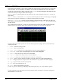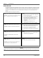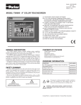
1
ConfigEd Lite Plus
DRIVES
Instruction
Manual
RG470795
ConfigEd Lite Plus
Instruction Manual
for use with ConfigEd Lite Plus Ver. 3.x
Copyright © 2005 by SSD Drives, Inc.
All rights strictly reserved. No part of this document may be stored in a retrieval system, or transmitted, in any form of by any means to persons not employed by a SSD Drives company without written
permission from SSD Drives, Inc.
Although every effort has been taken to ensure the accuracy of this specification, it may be necessary, without notice, to make amendments or correct omissions in this document. SSD Drives, Inc. cannot
accept responsibility for damage, injury, or expenses resulting therefrom.
Printed in the USA
RG470795 Issue 3.2
!
Safety Information
PLEASE READ THIS INFORMATION BEFORE INSTALLING THE SOFTWARE.
Personnel
Qualified personnel should carry out installation, operation and maintenance of the software. A qualified person is
someone who is technically competent and familiar with the installation process, operation and maintenance of this
software.
Procedures in this manual may contain Warnings and Notes. A Warning gives the reader the information, which, if
disregarded, could cause injury or death. A Note furnishes additional information for added emphasis or clarity.
The customer is responsible for assessing his or her ability to carry out the procedures in this manual. Make sure you
understand a procedure or the precautions necessary to carry it out safely before beginning. If you are unsure of your
ability to perform a function, or have questions about the procedures listed in the manual, contact SSD Drives, Inc.
customer service at (704) 588-3246.
WARNING!
This software is used specifically to configure the control of potentially dangerous motor control. The
user assumes all liability and risk for the performance, application, and reliability of all control systems
configured with this software. It is the users responsibility to understand thoroughly and to check
independently all configurations before commissioning any equipment controlled by this software. SSD
Drives, Inc. accepts no liability for the application of the software.
ConfigEd Lite Plus
i
ii
ConfigEd Lite Plus
FOR USE WITH CONFIGED LITE PLUS VER. 3.X
Contents
Chapter 1
Introduction
1
What is configed Lite Plus............................................................................................................................................................................................................. 1
Drive compatibility ........................................................................................................................................................................................................................... 1
Minumum System Requirements................................................................................................................................................................................................. 1
Noise .........................................................................................................................................................................................................................................................2
Chapter 2
Handling
3
Unpacking instructions ...................................................................................................................................................................................................................3
Special handling.................................................................................................................................................................................................................................3
Chapter 3
Installation & Setup
5
Installation procedure.................................................................................................................................................................................................................... 5
Autorun Install ............................................................................................................................................................................................................................ 5
Manual Install.............................................................................................................................................................................................................................. 5
Starting the program .......................................................................................................................................................................................................................8
Choosing the drive............................................................................................................................................................................................................................8
Drive communication setup ........................................................................................................................................................................................................ 9
Chapter 4
Starting up a 590+ Drive
11
Commissioning the drive.............................................................................................................................................................................................................. 11
Motor parameters...........................................................................................................................................................................................................................12
Control parameters........................................................................................................................................................................................................................ 13
Autotuning........................................................................................................................................................................................................................................... 14
Motor rotate check ........................................................................................................................................................................................................................16
Rotation Error ............................................................................................................................................................................................................................17
Chapter 5
Starting up a 650V Drive
19
Commissioning the drive.............................................................................................................................................................................................................19
Motor parameters......................................................................................................................................................................................................................... 20
Control parameters........................................................................................................................................................................................................................21
Autotune .............................................................................................................................................................................................................................................. 22
Stationary Autotune.............................................................................................................................................................................................................23
Rotating Autotune.................................................................................................................................................................................................................24
Autotune Errors....................................................................................................................................................................................................................... 25
ConfigEd Lite Plus
iii
FOR USE WITH CONFIGED LITE PLUS VER. 3.X
Contents (cont.)
Chapter 6
Starting up a 690+ Drive
27
Commissioning the drive...........................................................................................................................................................................................................27
Motor parameters......................................................................................................................................................................................................................... 28
Control parameters...................................................................................................................................................................................................................... 29
Autotune .............................................................................................................................................................................................................................................. 30
Stationary Autotune.............................................................................................................................................................................................................. 31
Rotating Autotune..................................................................................................................................................................................................................32
Autotune Errors........................................................................................................................................................................................................................33
Chapter 7
Home Screen
35
Running the drive ............................................................................................................................................................................................................................ 35
Parameter list views..................................................................................................................................................................................................................... 36
online Monitoring .......................................................................................................................................................................................................................... 39
Custom Monitoring List View ........................................................................................................................................................................................40
Chart Function .......................................................................................................................................................................................................................... 41
Chapter 8
Troubleshooting
43
Mismatched Baud Rates ............................................................................................................................................................................................................ 43
Baud Rate Set Too High ............................................................................................................................................................................................................. 43
Wrong Communications Port................................................................................................................................................................................................. 43
Drive P3 Mode Set Wrong ...................................................................................................................................................................................................... 43
Error Messages...............................................................................................................................................................................................................................44
Chapter 9
Appendix
45
CELite+..................................................................................................................................................................................................................................................45
Home Screen Buttons..........................................................................................................................................................................................................45
iv
ConfigEd Lite Plus
Chapter 1
Introduction
Chapter 1
Introduction
WHAT IS CONFIGED LITE PLUS
ConfigEd Lite Plus (CELite+) is newest addition to SSD Drives’ software suite for drives. This enhanced software
package supports all current-production SSD Drive products.
Windows-based CELite+ provides you with the ability to adjust all drive parameters, autotune your application and
chart key variables while on-line! It’s like having a built-in chart recorder where you can monitor trends in load, speed,
and other operating conditions. You will benefit by your ability to monitor conditions as changes are made to
production rates, process and material changes.
IMPORTANT
Previous versions of CELite+ contained CELite for drive configurations. This component is no longer
contained in CELite+. Use the separate version of CELite for drive configurations. CELite is freely
available on our web site at:
www.ssddrives.com
DRIVE COMPATIBILITY
590+ Series Digital DC Drives, All Firmware versions.
650V Series Digital AC Drives, Firmware 4.2 or newer.
690+ Series Digital AC Drives, Firmware 4.6 or newer.
MINUMUM SYSTEM REQUIREMENTS
CELite + is designed to be used with PC’s equipped with:
•
Pentium II 233MHz or better
•
800x600 screen resolution, supported by Microsoft Windows
•
Microsoft Windows 98 or later, or Microsoft Windows NT 4.0 or later
•
24 MB RAM for Windows 98, 32 MB for Windows NT
•
Microsoft Internet Explorer version 4.01 or later (version 4.01 Service Pack 1 or later for DHTML application
developers, and 4.x for end-users of these applications).
•
12 MB hard drive space required.
•
Standard RS232 Serial port with 9 pin male connector. (Special adapters for USB serial ports are available from
SSD Drives.)
ConfigEd Lite Plus
1
Chapter 1
Introduction
NOISE
Ground noise may disturb the P3 serial communications link. It is created by ground loops caused when both the
computer and the drive are grounded. CELite+ has a built-in retry routine to deal with occasional electrical noise.
Continuous noise, however, will cause extremely slow communications between the computer and the drive.
In systems with large amount of electrical noise (for example, systems containing AC drives) it may be necessary to
break the ground loop to achieve usable communications. The ground loop can be broken by:
•
Using a battery-powered notebook computer rather than a plug-in model since most notebook computers are not
grounded.
•
Installing an RS232 isolator module between the computer and the P3 socket.
•
Wrapping the UDP cable through ferrite rings on both ends of the cable.
WARNING!
Do not use any connectors, adapters, and/or cables other than those supplied by SSD Drives. Failure to use
materials supplied by SSD Drives can result in severe damage to equipment and injury to personnel and
will void the SSD Drives warranty.
2
ConfigEd Lite Plus
Chapter 2
Handling
Chapter 2
Handling
UNPACKING INSTRUCTIONS
Before you install and use CELite+, verify the completeness of your package. It should include:
•
CELite+ user manual (Part Number HA470795U000)
•
Installation CDROM and case (Part Number RD470795)
•
UDP cable and adapter (Part Number CM351909)
•
User License for CELite+
If any item on this list is missing, contact the SSD Drives Customer Service at 704-588-3246.
SPECIAL HANDLING
Proper care must be shown in the handling of the materials used for the program. The installation disk should be kept in
a clean, dry environment within a relatively constant range of temperature and humidity. Keep the CELite+ disk far
from any sources of extreme heat, magnetism and electrical fields, including permanent magnet motors, as the magnetic
or electrical fields may erase the information on the disk.
WARNING!
CELite+ is a powerful software tool specifically designed to configure drives. It is possible to create
potentially dangerous drive configurations. The user assumes all liability and risk for the performance,
application, reliability, and safety of drives implemented using this tool. It is the responsibility of that user
to understand the configurations thoroughly and check them independently prior to installations and
operation of any equipment. SSD Drives can accept no liability for the application of this software.
ConfigEd Lite Plus
3
Chapter 2
Handling
This page intentionally left blank.
4
ConfigEd Lite Plus
Chapter 3
Installation & Setup
Chapter 3
Installation & Setup
WARNING!
Please uninstall (remove) all previous versions of CELite+ prior to installation. This may include the
manual removal of a DeskTop Icon.
INSTALLATION PROCEDURE
Autorun Install
With Windows launched, insert the CELite+ CDROM disk into your CD Drive. The install program should launch
automatically, if not follow the manual installation procedure.
Manual Install
Using the cursor click on the Start button on the desktop, then click on RUN.
When the run dialog box appears, type in the drive letter for your CD Drive. If you do not know your CD Drive letter,
click on browse to search for it. In this example the CD drive letter is D. Type d:\setup and then click OK.
ConfigEd Lite Plus
5
Chapter 3
Installation & Setup
The following window will appear to show you that the CELite+ installation has begun, click on OK to continue.
This window will show the folder where the program will be installed on the hard drive. Click on the Computer
button to proceed to the next step of installation.
IMPORTANT
Please do not change the installation directory.
6
ConfigEd Lite Plus
Chapter 3
Installation & Setup
The following window will appear to show the program group where the CELite+ shortcut will be installed. Click on
the Continue button to proceed to the next step of installation.
After the program group has been selected, the program will start copying files to your hard drive. The following status
window will appear to show you the progress of the installation. It is not uncommon for error messages or file copy
messages to appear during this procedure. Error messages should be copied in the unlikely event they need to be
reported although they should be otherwise ignored. As long as the application being deployed is known to be the
“latest”, always replace an existing file if prompted.
After the program is finished loading the files, the following window will appear. Click on OK to finish the installation.
ConfigEd Lite Plus
7
Chapter 3
Installation & Setup
STARTING THE PROGRAM
Start the program by either clicking on the CELite+ shortcut on the desktop or using the start menu.
To use the start menu, click on Start, then Programs, then the SSD Drives program group, then on the
CELPlus shortcut
CHOOSING THE DRIVE
After launching the program, click on the button for the desired drive series. The initial loading of data may take a
few minutes on slower systems.
8
ConfigEd Lite Plus
Chapter 3
Installation & Setup
DRIVE COMMUNICATION SETUP
SSD Drives contain a serial port socket, similar to a telephone handset socket, for RS232 communication to the
CELite+ software. This port is commonly referred to as the P3 port. Please refer to the drive manual for location and
setup of the port on the drive.
TIP
On smaller horsepower AC drives, 5 hp and below, the keypad must be removed and the serial cable
plugged into the keypad serial port. Larger horsepower AC drives 7.5 hp and above, have a separate P3
serial port. All DC drives have a separate P3 serial port.
WARNING!
Do not use any connectors, adapters, and/or cables other than those supplied by SSD Drives. Failure to
use materials supplied by SSD Drives can result in severe damage to equipment and injury to personnel,
and will void the SSD Drives warranty.
ConfigEd Lite Plus
9
Chapter 3
Installation & Setup
This page intentionally left blank.
10
ConfigEd Lite Plus
Chapter 4
Starting up a 590+ Drive
Chapter 4
Starting up a 590+ Drive
COMMISSIONING THE DRIVE
Once the configuration has been created and installed in the drive as described in the previous chapters, the drive is
ready to be commissioned. If starting with a drive that has a previous configuration installed, go Online then Update the
CELite configuration first before proceeding. For more details, refer to the previous chapters.
The CELite+ program guides through the startup process, starting with entering the motor information, entering control
setup information, performing an autotune and a motor rotation check. Start by going online with the drive. Click the
Go Online button on the CELite+ home screen. After the Go Online button is green, click on the
AutoStart123 button.
When this screen appears, read the note and click on Continue.
ConfigEd Lite Plus
11
Chapter 4
Starting up a 590+ Drive
MOTOR PARAMETERS
The motor parameter screen, shown below, shows up next. If the motor information was entered in the configuration in
CELite, just verify the information. After verifying the entered information, click on Next. Refer to the drive manual if
you have any questions about the parameters.
WARNING
Make sure all information entered for the motor is exactly as it is shown on the motor nameplate. DO
NOT enter any information you are not sure is accurate. Contact the motor manufacture if the motor
information is not available.
WARNING
If the drive is setup for either tachometer or encoder feedback, verify that the tachometer or encoder is
connected and appropriately calibrated to the drive.
Note
CELite+ does not support Field weakening setup at this time. It will have to be setup manually after all
tests have been successfully completed in CELite+.
The following screen will prompt to download the changes. Click on Yes if any changes have been made or No if not.
12
ConfigEd Lite Plus
Chapter 4
Starting up a 590+ Drive
Note
The changes can be downloaded after entering the information in the next section.
CONTROL PARAMETERS
The following display shows the Control Parameters screen. After the information has been entered or verified, click on
the Next button. Refer to the drive manual for questions on the parameters.
Click on the Yes button in the following window to download the changes into the drive. It will download only new
information entered in the Motor and Control parameter screens.
ConfigEd Lite Plus
13
Chapter 4
Starting up a 590+ Drive
AUTOTUNING
The Autotune screen appears next.
The autotune on a DC drive primarily calibrates the current loop parameters. It tunes the drive to the motor, and is very
important for proper drive performance. All DC drives should be autotuned.
This window displays four diagnostic parameters, Coast Stop, Program Stop, External Trip and Enable. These
parameters are the primary logic inputs on the drive and all must be in a Ready state for the autotune to begin. You can
click the Refresh button to update the status of these diagnostic values. If any of these values are not ready, check the
connections on the drive and any safety interlocks.
Autotune adjusts three current loop parameters Discontinuous current, Proportional gain, and Integral gain. The default
values are 12.00%, 45.00, and 3.50 respectively. After the autotune has been completed successfully, these values
should change and must be saved in the drive. CELite+ will prompt to save the parameters after the autotune is finished.
WARNING
During an autotune the shaft may turn, but for more accurate performance the armature should remain
stationary. If you are tuning a Shunt wound DC motor the shaft should not turn; but it may have enough
residual magnetism to cause the shaft to turn. If it turns very slowly, the tuning will not be affected. If it
turns above 10% speed, the shaft must be locked. Stabilized shunt, compound, and permanent magnet
DC motors all need to have their shafts locked. The locking device should be strong enough to hold the
full torque of the motor.
Click on Begin to start the autotune process. After the autotune process begins, the program will prompt to download
changes to the drive. If the changes have already been downloaded, click No otherwise click Yes.
14
ConfigEd Lite Plus
Chapter 4
Starting up a 590+ Drive
When this warning screen appears, click Yes to continue.
The drive will now try to start the AutoOpen process by pulling in the drive contractor and pulsing the armature with
current. The process will take about 30 seconds. If it completes successfully, the following screen will appear, click
Yes to continue to the rotate screen.
The following screens are some of the errors that can pop up during an autotune.
If this error appears, check that the:
1.
Armature leads are connected.
2.
Jumper present between drive terminals B3 and A6
is in place.
Click on OK to acknowledge error, and retry autotune.
This error will only appear if you stopped the autotune
using the program or the drive terminals.
Click on OK to acknowledge error, and retry autotune.
If this error appears, check for:
1.
Motor rotation more than 20% with encoder or
tachometer feedback.
2.
Improper calibration for the encoder or
tachometer.
3.
Improper calibration for armature voltage.
Click on OK to acknowledge error, and retry autotune.
ConfigEd Lite Plus
15
Chapter 4
Starting up a 590+ Drive
MOTOR ROTATE CHECK
Now, you are now ready to check the direction of rotation of the motor and the polarity between the motor and the
feedback.
This window displays four diagnostic parameters, Coast Stop, Program Stop, External Trip and Enable. These
parameters are the primary logic inputs on the drive and all must be in a Ready state for the rotate test to begin. Click
the Refresh button to update the status of these diagnostic values. If any of these values are not Ready, check the
drive connections and any safety interlocks.
The speed feedback window reflects the choice set on the motor parameter screen. During this test the program sets
force the drive to armature voltage feedback to prevent the motor from running away. After the rotate test has been
completed successfully, the program will prompt to reset the speed feedback back to the original choice.
Click Begin to start the rotate test. The following screen is to warn that the motor is about to turn. Click Yes to
continue.
The program memorizes the selected speed feedback and then sets the drive to armature voltage feedback. Then it sends
a run command to the drive with a 5% speed demand. After the drive starts, the program compares the initial feedback
source for polarity and scaling to that of the 5% speed demand.
IMPORTANT
Do not leave the rotate screen until the test is completed. If the screen is left, the drive will remain in
Armature voltage feedback and will have to be manually reset.
16
ConfigEd Lite Plus
Chapter 4
Starting up a 590+ Drive
The drive should run for a few seconds and then ask if the direction is correct. The direction of the motor is based on a
forward (positive) speed demand to the drive. If the direction of the motor is correct for forward, click Yes otherwise
click No.
Next the program displays one of six messages. If the following message appears, continue with the rotate test. Skip to
the “Rotation Error” section if any other message appears. Click on OK to continue. A Start button will appear on the
rotate screen. Click on Start to start the drive. Last the program will prompt to change the speed feedback to the
initial setting. Click on Yes to switch back to the initial setting, or No to stay in armature voltage feedback.
Rotation Error
If one of the following messages appear, follow the directions to correct the problem. Then repeat the rotate test again.
Motor direction is ok, but the feedback is missing.
Check the following:
1.
Tachometer or Encoder feedback board missing or not
connected.
2.
Feedback source missing or misconnected.
Check connections, feedback boards, tachs and encoders.
Click on OK and retry rotating test.
Motor direction is ok, but the feedback polarity is reversed.
The following actions are required:
1.
Tachometer feedback – Reverse the two tachometer leads.
2.
Encoder feedback – CELite+ will automatically invert the
encoder sign bit to correct the polarity.
Click on OK and retry rotating test.
ConfigEd Lite Plus
17
Chapter 4
Starting up a 590+ Drive
Motor direction is reversed and feedback polarity is reversed.
The following actions are required:
1.
Reverse the two armature leads.
2.
Tachometer feedback – Reverse the two tachometer leads.
3.
Encoder feedback – CELite+ will automatically invert the
encoder sign bit to correct the polarity.
Click on OK and retry rotating test.
Motor direction is reversed and feedback is missing.
Check the following:
1.
Reverse the two armature leads.
2.
Tachometer or Encoder feedback board missing or not
connected.
3.
Feedback source missing or misconnected.
Check connections, feedback boards, tachs and encoders.
Click on OK and retry rotating test.
Motor direction is reversed and feedback is correct.
The following action is required:
1.
Reverse the two armature leads.
Click on OK and retry rotating test.
Motor current not detected or feedback out of range.
Check the following:
1.
Motor not connected or not properly connected.
2.
Feedback not scaled correctly.
3.
CELite+ timed out or computer resources low.
Click on OK and retry rotating test.
After the rotate test is completed successfully, click the Parameters Save button, click the Update button, and
then continue running the drive in local mode using the Home screen. If the motor runs satisfactory, commissioning is
complete.
18
ConfigEd Lite Plus
Chapter 5
Starting up a 650V Drive
Chapter 5
Starting up a 650V Drive
COMMISSIONING THE DRIVE
Once the configuration has been created and installed in the drive as describe in the previous chapters, the drive is now
ready to be commissioned. If starting with a drive that has a previous configuration installed, go Online then Update the
CELite configuration first before proceeding. For more details, refer to the previous chapters.
The CELite+ program guides through the startup process, starting with entering the motor information, entering control
setup information, performing an autotune and a motor rotation check. Start by going online with the drive. Click the
Go Online button on the CELite+ home screen. After the Go Online button is green, click on the
AutoStart123 button.
When this screen appears read the note and click on Continue.
ConfigEd Lite Plus
19
Chapter 5
Starting up a 650V Drive
MOTOR PARAMETERS
The motor parameter screen, shown below, shows up next. If the motor information was entered in the configuration in
CELite, just verify the information. After verifying the entered information, click on Next. Refer to the drive manual
for questions on the parameters.
WARNING!
Make sure all information entered for the motor is exactly as it is shown on the motor nameplate. DO
NOT enter any information you are not sure is accurate. Contact the motor manufacture if the motor
information is not available.
There are two different modes of operation the 650V can be setup for, Volts/Hz, and Sensorless Vector. Each one of the
modes has specific parameters that need to be entered. After choosing one of the modes, CELite+ will show the
parameters needed for the specific control mode.
The following is a brief description of the three control modes:
•
The Volts/Hz mode is open loop and requires no speed feedback. Enter in the appropriate information and go on to
the control parameter section.
•
The Sensorless Vector mode is also open loop, but it has better torque and speed regulation. Enter in the
appropriate information and go on to the control parameter section.
For more information on the different options and control modes refer to the drive manual.
20
ConfigEd Lite Plus
Chapter 5
Starting up a 650V Drive
CONTROL PARAMETERS
The following display shows the Control Parameters screen. After the information has been entered or verified, click on
the Next button. Refer to the drive manual for questions on the parameters.
In the vector mode, the motor current is equal to the Magnetizing current and the load current; Torque is equal to the
load only.
The dynamic braking can only be setup on drives that have been fitted with the braking transistor. Refer the to the
model number and the drive manual to verify if the drive has this option.
After the information has been entered, click on the Download Changes button to download to the drive.
The Download Changes button will only change the information entered in the two parameter screens. The
program may automatically prompt to download changes, if so click on Yes.
If the drive is setup for Volts/Hz mode, the program will skip the autotune screen.
ConfigEd Lite Plus
21
Chapter 5
Starting up a 650V Drive
AUTOTUNE
The Autotune screen appears next. The autotune is only required for the vector mode.
Warning!
To perform an autotune on an AC drive, the motor has to be able to turn freely. To achieve the best
results the motor shaft must not be connected to any device (Like Gearboxes, pulleys, couplings, etc.).
Before attempting an autotune, all motor parameters MUST be entered into the drive.
This window displays four diagnostic parameters, Coast Stop, Fast Stop, Contactor Closed, and Enable. These
parameters are the primary logic inputs on the drive and all must be in a Ready state for the autotune to begin. Click the
Refresh button to update the status of these diagnostic values. If any of these values are not Ready, check the
connections on the drive and any safety interlocks.
There are two modes of autotuning on an AC drive, Stationary and Rotating. The preferred mode is the rotating
autotune. There are many parameters the autotune will adjust in the drive, only five of those parameters are shown on
the autotune screen. After the autotune has been completed successfully, these values should change and must be saved
to the drive.
Click on the white circle next to the mode of autotuning to be preformed. A black dot should appear in the circle and a
warning window will appear. Skip to the appropriate section below.
22
ConfigEd Lite Plus
Chapter 5
Starting up a 650V Drive
Stationary Autotune
The Stationary Autotune should only be used if the motor cannot spin freely. During this autotune the motor will not
spin, and it will only identify a limited set of motor characteristics. The following are some of the drawbacks to a
stationary autotune:
•
User has to enter the correct value of magnetizing current.
•
Cannot operate the motor above base speed.
•
User has to manually check the encoder polarity and adjust if necessary.
If Stationary Autotune is chosen, the following window will appear. Click on OK, and compare the Magnetizing current
value shown on the screen to that on the motor nameplate. If the value is wrong, enter the proper value and continue.
Click on Begin to start the autotune process. The following window will appear to warn that the program will assume
control of the drive. Click on Yes to continue.
CELite+ will now perform an autotune on the drive. If the autotune completes successfully the following window will
appear. Click on Yes, and proceed to the Home screen to run the drive. If an error occurs skip to the Autotune error
section.
ConfigEd Lite Plus
23
Chapter 5
Starting up a 650V Drive
Rotating Autotune
The Rotating Autotune mode of tuning will give the best performance of the drive. The motor shaft will spin from zero
to base speed and then to maximum speed. This mode of tuning will also check the encoder feedback polarity, and
toggle the encoder polarity if necessary. The following are some drawbacks to a rotating autotune:
•
The motor shaft cannot be connected to anything.
•
The tuning process can only characterize the motor up to 30% above the Max speed. If you need to go
faster than this speed, perform another autotune.
If Rotating Autotune is chosen, the following window will appear, Click on OK to continue.
Click on Begin to start the autotune process. The following window will appear. Click on Yes to continue.
Next the program displays a warning that it will assume control of the drive. Click on Yes to continue.
CELite+ will now perform an autotune on the drive. If the autotune completes successfully the following message will
appear. Click on Yes and proceed to the Home screen to run the drive. If an error occurs skip to the Autotune error
section.
24
ConfigEd Lite Plus
Chapter 5
Starting up a 650V Drive
Autotune Errors
Below are some of the errors that can occur during an autotune.
This error will only appear if you stopped the autotune
using the program or the drive terminals.
Click on OK to acknowledge error and retry autotune.
If this error appears, check the following:
1.
Coast stop, fast stop, enable, external trip, and motor thermal
are all high.
2.
CELite+ is still in control of the drive.
Click on OK to acknowledge error and retry autotune.
If this window appears you do not need to preform an autotune
Click on OK and proceed to the home screen section.
There are multiple errors that can appear in this
window, please refer to the 650 installation
manual, Trips and Fault Finding chapter, for
more information.
Click on OK to acknowledge error and retry
autotune.
After autotune has completed successfully, continue to the home screen section.
ConfigEd Lite Plus
25
Chapter 5
Starting up a 650V Drive
This page intentionally left blank.
26
ConfigEd Lite Plus
Chapter 6
Starting up a 690+ Drive
Chapter 6
Starting up a 690+ Drive
COMMISSIONING THE DRIVE
Once the configuration has been created and installed in the drive as describe in the previous chapters, the drive is now
ready to be commissioned. If starting with a drive that has a previous configuration installed, go Online then Update the
CELite configuration first before proceeding. For more details, refer to the previous chapters.
The CELite+ program guides through the startup process, starting with entering the motor information, entering control
setup information, performing an autotune and a motor rotation check. Start by going online with the drive. Click the
Go Online button on the CELite+ home screen. After the Go Online button is green, click on the
AutoStart123 button.
When this screen appears read the note and click on Continue.
ConfigEd Lite Plus
27
Chapter 6
Starting up a 690+ Drive
MOTOR PARAMETERS
The motor parameter screen, shown below, shows up next. If the motor information was entered in the configuration in
CELite, just verify the information. After verifying the entered information, click on Next. Refer to the drive manual
for questions on the parameters.
WARNING!
Make sure all information entered for the motor is exactly as it is shown on the motor nameplate. DO
NOT enter any information you are not sure is accurate. Contact the motor manufacture if the motor
information is not available.
There are three different modes of operation the 690+, Volts/Hz, Sensorless Vector, and Closed Loop Vector. Each one
of the modes has specific parameters that need to be entered. After choosing one of the modes, CELite+ will show the
parameters needed for the specific control mode.
The following is a brief description of the three control modes:
•
The Volts/Hz mode is open loop and requires no speed feedback. Enter in the appropriate information and go on to
the control parameter section.
•
The Sensorless Vector mode is also open loop, but it has better torque and speed regulation. Enter in the
appropriate information and go on to the control parameter section.
•
The Closed Loop Vector mode requires encoder feedback to close the speed loop. It has very good torque and
speed regulation. The encoder feedback can be connected through an Encoder techbox or system board. Enter in
the appropriate information and go on to the control parameter section.
For more information on the different options and control modes refer to the drive manual.
28
ConfigEd Lite Plus
Chapter 6
Starting up a 690+ Drive
CONTROL PARAMETERS
The following display shows the Control Parameters screen. After the information has been entered or verified, click on
the Next button. Refer to the drive manual for questions on the parameters.
In the vector modes, the motor current is equal to the Magnetizing current and the load current; Torque is equal to the
load only.
The dynamic braking can only be setup on drives that have been fitted with the braking transistor. Refer the to the
model number and the drive manual to verify if the drive has this option.
After you are finished with this screen you should download the information you have entered. Click on the Download
Changes button to accomplish this.
The Download Changes button will only change the information entered in the two parameter screens. The program
may prompt to download changes, if so click Yes.
If the drive is setup for Volts/Hz mode, the program will skip the autotune screen.
ConfigEd Lite Plus
29
Chapter 6
Starting up a 690+ Drive
AUTOTUNE
The Autotune screen appears next. The autotune is only required for the vector modes.
WARNING!
To perform an autotune on an AC drive, the motor has to be able to turn freely. To achieve the best
results the motor shaft must not be connected to any device (Like Gearboxes, pulleys, couplings, etc.).
Before attempting an autotune, all motor parameters MUST be entered into the drive.
This window displays four diagnostic parameters, Coast Stop, Fast Stop, Contactor Closed, and Enable. These
parameters are the primary logic inputs on the drive and all must be in a Ready state for the autotune to begin. You can
click the Refresh button to update the status of these diagnostic values. If any of these values are not Ready, check
the connections on the drive and any safety interlocks.
There are two modes of autotuning on an AC drive, Stationary and Rotating. The preferred mode is the rotating
autotune. There are many parameters the autotune will adjust in the drive, only five of those parameters are shown on
the autotune screen. After the autotune has been completed successfully, these values should change and must be saved
to the drive.
Click on the white circle next to the mode of autotuning to be preformed. A black dot should appear in the circle and a
warning window will appear. Skip to the appropriate section below.
30
ConfigEd Lite Plus
Chapter 6
Starting up a 690+ Drive
Stationary Autotune
The Stationary Autotune should only be used if the motor can not spin freely. During this autotune the motor will not
spin, and it will only identify a limited set of motor characteristics. The following are some of the drawbacks to a
stationary autotune:
•
User has to enter the correct value of magnetizing current.
•
Cannot operate the motor above base speed.
•
User has to manually check the encoder polarity and adjust if necessary.
If Stationary Autotune is chosen, the following window will appear. Click on OK, and compare the Magnetizing current
value shown on the screen to that on the motor nameplate. If the value is wrong, enter the proper value and continue.
Click on Begin to start the autotune process. The following window will appear to warn that the program will assume
control of the drive. Click on Yes to continue.
CELite+ will now perform an autotune on the drive. If the autotune completes successfully the following window will
appear. Click on Yes, and proceed to the Home screen to run the drive. If an error occurs skip to the Autotune error
section.
ConfigEd Lite Plus
31
Chapter 6
Starting up a 690+ Drive
Rotating Autotune
The Rotating Autotune mode of tuning will give the best performance of the drive, especially in closed loop vector
mode. The motor shaft will spin from zero to base speed and then to maximum speed. This mode of tuning will also
check the encoder feedback polarity and toggle the encoder polarity if necessary. The following are some drawbacks to
a rotating autotune:
•
The motor shaft cannot be connected to anything.
•
The tuning process can only characterize the motor up to 30% above the Max speed. If you need to go
faster than this speed, perform another autotune.
If Rotating Autotune is chosen, the following window will appear, Click on OK to continue.
Click on Begin to start the autotune process. The following window will appear. Click on Yes to continue.
Next the program displays a warning that it will assume control of the drive. Click on Yes to continue.
CELite+ will now perform an autotune on the drive. If the autotune completes successfully the following message will
appear. Click on Yes and proceed to the Home screen to run the drive. If an error occurs skip to the Autotune error
section.
32
ConfigEd Lite Plus
Chapter 6
Starting up a 690+ Drive
Autotune Errors
Below are some of the errors that can occur during an autotune.
This error will only appear if you stopped the autotune
using the program or the drive terminals.
Click on OK to acknowledge error and retry autotune.
If this error appears, check the following:
3.
Coast stop, fast stop, enable, external trip, and motor thermal
are all high.
4.
CELite+ is still in control of the drive.
Click on OK to acknowledge error and retry autotune.
If this window appears you do not need to perform an autotune
Click on OK and proceed to the home screen section.
There are multiple errors that can appear in this
window, please refer to the 690+ installation
manual, Trips and Fault Finding chapter, for
more information.
Click on OK to acknowledge error and retry
autotune.
After autotune has completed successfully, continue to the home screen section.
ConfigEd Lite Plus
33
Chapter 6
Starting up a 690+ Drive
This page intentionally left blank.
34
ConfigEd Lite Plus
Chapter 7
Home Screen
Chapter 7
Home Screen
After setting up and autotuning the drive, use the Home screen to control the drive. It is basically a software version of
the keypad on the drive. CELite+ will control the drive through the serial port on the drive. To use this screen, you will
have to be ONLINE and set the drive to local (LOC) mode.
Below the gauges and pots is a representation of the drive IO terminals. Analog terminals will be white with a 0.0
value, green when positive, and light blue when negative. As the value approaches 100 percent the color brightens.
The digital terminals show green when ON and red when OFF. The illustration above shows the drive running at 100%
forward with terminal 6 on at 100%, and terminals 19, 23, and 24 ON.
WARNING!
Before running the drive make sure everyone is clear of the motor. Make sure all interlocks and
emergency stops are wired and operational, and that the motor is properly mounted.
RUNNING THE DRIVE
The following functions are needed to run the drive. To activate a function, click on the desired button with the cursor.
•
RUN – Send a run command to the drive.
•
STOP – Send a stop command to the drive.
•
LOC – In this switch position, the drive will be in Local mode and is controlled by CELite+ or the keypad on the
drive.
•
REM - In this switch position, the drive will be in Remote mode and is controlled by terminals on the drive.
•
FWD – In this switch position, the drive will rotate in a forward direction.
•
REV – In this switch position, the drive will rotate in a reverse direction.
•
RESET – To reset the drive if a fault occurs. Fault information will be shown below the RESET button.
•
Setpoint – Send a speed demand to the drive. Drag the dial with the cursor to increase or decrease the speed
setpoint or double-click inside the dial to type in a speed setpoint.
ConfigEd Lite Plus
35
Chapter 7
Home Screen
•
Current Setpoint – Send a current demand to the drive. Drag the dial with the cursor to increase or decrease
the current setpoint or double-click inside the dial to type in a current setpoint.
•
Meters – These meters have a digital and a needle readout.
•
Speed % - Speed feedback on the drive.
•
Current % - Current feedback on the drive.
•
Torque % - Torque feedback on the AC drives only.
WARNING!
Do not click the OFFLINE button or close the software while running the drive with the Home screen.
To run the drive, simply click on the RUN button and dial in the desired speed demand. Watch the meters for speed
feedback and current feedback to ensure proper performance.
PARAMETER LIST VIEWS
The parameter list views show the drive parameters in a spreadsheet format. Click on the + sign to expand the
Parameter List Views in the tree view window.
There are four basic lists of parameters, Different from Default, Custom Monitoring, All and Setup. The parameter
lists are defined as follows:
1.
Different from Default – a listing of only the parameters different from the factory default values.
2.
Custom Monitoring – a listing of only the parameters chosen by the user to be displayed.
3.
All – a listing of all the drive parameters.
4.
Setup – the parameters listed in the appropriate function they perform in the drive.
Click on the + sign to expand a list in the above tree view window and – to compress a list.
36
ConfigEd Lite Plus
Chapter 7
Home Screen
To open a List view, click the desired list view in the tree view window. The Parameter List View window appears as
the following:
The top task bar shows which list view is being shown. The following buttons can be used to move between the list
views:
1.
Prev – Go to the previous list view. If you are at the first list view, it will go to the last list view.
2.
Next - Go to the next list view. If you are at the last it will go to the first list view.
3.
Exit – Return to the home screen.
The following is a listing of the information in the window.
1.
Description window – detailed information on the highlighted parameter.
2.
Parameter list window- multiple columns of information listed from left to right below:
1.
Tag – Parameter number in the drive
2.
Tag Name – Parameter name
3.
Drive – Parameter value from the drive
4.
Configured Value – Parameter value from the CELite configuration
5.
Default – Parameter value factory default
6.
Range – Range for the given parameter
7.
T, M – Trace on Chart or Monitor this parameter. ONLY the parameters on the Monitor list will be
modifiable while Charting.
3.
List Only Modified – Only shows the parameters changed and pending Download which are viewable on
the current list view
4.
Auto Download on – Automatically download any changed value in the list view after this function is
checked.
5.
Print Form – print all parameters in the current list view. If the user is on the “All” Listview, this is a large
amount of documentation.
ConfigEd Lite Plus
37
Chapter 7
6.
Home Screen
Total – Total number of parameters in the current list view.
By default the list views display the information sorted by the tag number. The list view can be toggled between
ascending and descending order by clicking on the Tag# button and changing the direction of the arrow. The list
view can also be toggled between alphabetical or reverse alphabetical order by clicking on the Tag Name button.
Any parameter can be changed by clicking on it in the Configured Value column and entering in the value.
Once a value has been changed it will be highlighted until it is downloaded into the drive. The new information will
not be downloaded to the drive until the Download Changes button is clicked, unless the AUTO DOWNLOAD ON
has been checked. The following window will appear to warn that the program is about to download the information
to the drive.
Note
Any parameters that were changed before this function is checked must be downloaded with the
Download Changes button.
To view a list of all the parameters that have been changed in the list views, click on the List Only Modified
button. The button will only appear after a parameter has been modified in the list views.
38
ConfigEd Lite Plus
Chapter 7
Home Screen
The Print Form button will print all the parameters in the current list view only. It will print in a landscape page
format, with approximately 29 parameters per page.
Note
Double clicking on the Tag Name will refresh the parameter value from the drive when online. Clicking
on the Refresh button at the bottom of the screen will refresh the entire current List View.
Warning !
When using the Online Chart function on a 590+ drive, the drives PNOs 112, 113, 114 & 115 are used
for this Chart function. If these PNOs are being used for Serial Communications (i.e.DeviceNet,
EtherNet and etc), the links to these PNOs will be temporarily disconnected during the operation of the
Online Chart and loss of Serial Communications using these PNOs may occur.
These PNOs will be re connected when the drive power is removed and re applied. If a ‘Parameter Save’
is performed on the 590+ drive while these PNOs are disconnected, they will be permanently
disconnected.
ONLINE MONITORING
To send a parameter either to the online Chart or the Custom Monitoring list view, click on the T, M column
for the given parameter. The following window will appear:
ConfigEd Lite Plus
39
Chapter 7
Home Screen
The Custom Monitoring List is a special list view that will scan the drive and update the parameter with each
scan. Only these parameters may be modified when Charting. To add a parameter to the list, click on Add. To
remove a parameter from the list, click on Remove. Once a choice has made, click on OK. After the above window is
closed, there will be an M in the T,M column for the parameter added to the list. Skip to the Custom Monitoring
section for more information.
The Chart function is a software version of a chart recorder. To add the parameter to the chart, first choose one of
the channels, 1 – 4, for the parameter to be displayed, then click on Add. To remove a parameter from the chart,
choose the channel to be removed and then click on Remove. Once a choice has made, click on OK. After the above
window is closed, there should be a 1 - 4 in the T,M column for the parameter added to the list. This identifies the
channel the parameter will be shown on the chart. Skip to the Chart section for more information.
Custom Monitoring List View
The Custom Monitoring window displays the parameters selected in the previous section. There are two ways to
open the window. Click on Custom Monitoring on the tree view window or click on the Watch button on the
home screen.
When the Custom Monitoring list view is open, CELite+ will continually update the parameters on the list. The
parameter values appear in the Drive column of the window. The green Scanning Drive LED will flash on and
off during normal operation.
40
ConfigEd Lite Plus
Chapter 7
Home Screen
Chart Function
Note
To chart drive values, go Online before opening the Chart window. To Run the drive from the Chart
screen the application must also set the drive in Local before opening the Chart window.
The chart function allows the user to chart up to four drive parameters. There are two ways to start Chart function.
Click on Chart, under the Tree View window or click on the Chart button in the home screen.
The following is the chart window:
The bottom of the chart window shows information about the four parameters, channels, chosen to be charted. Each
channel will show the parameter number, parameter name and a digital readout of the parameter. The parameter being
charted can be changed by clicking, with the right mouse button, on the channel checkbox. A popup dialog window
appears which allows a new parameter to be selected, either directly typing a tag number or selecting from a list.
ConfigEd Lite Plus
41
Chapter 7
Home Screen
Each channel can be turned on or off by clicking, with the left mouse button, on the little white box to the right of the
parameter number. The color legend for each channel is shown in the upper right hand corner of the chart window.
The time base of the chart can be change by clicking on the sec/Div arrow and selecting the desired time base. The
time base should only be changed while the chart is stopped.
The Start and Stop buttons under the time base are used to start or stop the charting. Click on Exit to close the
chart window.
The Start and Stop buttons under Drive are used to start and stop the drive while on the chart page. The highlight
on the buttons will show the mode the drive is in, Red for stopped and Green for running.
The Change a Drive Value button is used for changing a parameter in the drive while on the chart page. The
only stipulation is that the parameter to be change must be added to the Custom Monitor list view before running
the chart function.
Once a channel has been turned on, a vertical scale will appear to the left of the chart window with the color of the
channel turned on. An example is shown below, channel 1 was turned on so a red vertical scale appeared.
The buttons that appear on the top of the chart have the following functions, starting with the left most button and
working to the right:
1.
Resume – Resumes scrolling of chart.
2.
Pause – Pauses scrolling of chart.
3.
Scroll mode – Use the cursor to scroll through the axes on the channel highlighted.
4.
Zoom mode – Use the cursor to Zoom through the axes on the channel highlighted.
5.
Zoom in – Zoom all axes in by a factor of x2 on all channels.
6.
Zoom out – Zoom all axes out by a factor of x2 on all channels.
7.
Zoom box – Draw a box on chart data to Zoom in on all axes on all channels.
8.
Cursor – Draw a line in the chart area to define a given point on the trace on the channel highlighted.
9.
Edit – Change properties for all aspects of the chart. This button is only available when chart is stopped.
10. Copy – Copy the current chart data to the clipboard.
11. Save – Save current chart data to a file.
12. Print – Print current chart data to the printer.
To scale the y-axis, edit the chart by modifying the Min and the Span of the y-axis of the Channel in question.
For more information on the chart function, refer to the plot pack version 2.0 manual. A copy of the manual can be
downloaded at www.iocomp.com.
42
ConfigEd Lite Plus
Chapter 8
Troubleshooting
Chapter 8
Troubleshooting
MISMATCHED BAUD RATES
The baud rates in the drive must match those in CELite+. Check the BAUD RATE setting on the drive under SERIAL LINKS.
Clicking on Reset in the Comms menu will cause the application to reset the comms port and automatically try to find the correct
baud rate required to communicate with the drive. CELite+ will only check COM1 and COM2 in this process. Using any other
comm. Port will require the user to manually configure the setting in the Comms Menu::Settings.
BAUD RATE SET TOO HIGH
Some older IBM-compatible computers can experience difficulty with the 19200 baud rate. For those computers, reduce
the baud rate until reliable communications occur or to 9600 on the drive and do a Comms::Reset in CELite+.
WRONG COMMUNICATIONS PORT
If the comm port is other than COM1 and COM2 go to the Command Comms menu, select another communications
port, and ensure your drive is connected to that port.
DRIVE P3 MODE SET WRONG
For a 590+ series drive, set:
SERIAL LINKS::SYSTEM PORT::P3 SETUP::MODE to IPS (ASCII)
SERIAL LINKS::SYSTEM PORT::P3 SETUP::P3 BAUD RATE to 19200.
For 650V drives, no special settings are required to communicate with ConfigEd Lite Plus. Simply plug into the
appropriate serial port on the drive.
Note
Not all 650V drives are fitted with a P3 serial port, refer to drive manual for more information.
For a 690+ series drive, set:
SETUP::COMMUNICATIONS::SYSTEM PORT (P3)::MODE to EI ASCII
The baud rate is fixed at 19200
ConfigEd Lite Plus
43
Chapter 8
Troubleshooting
ERROR MESSAGES
Error detection is designed into ConfigEd Lite to help prevent the execution of an inappropriate or dangerous command.
ConfigEd Lite displays error messages when it discovers a problem. The messages contain an error number and a brief
description. Some messages also have an error code expressed as PNO plus a two-character code identifying the type of
error. In case of irreconcilable errors, the error and code numbers may help the service technician help solve the
problem.
The most common error messages are as follows:
Code – Error #6453 Serial Comms failed.
Description – Serial comms has not responded as expected.
PNO II, indicates that it failed to read ID (II).
Code – Error #6449 Serial Comms failed.
Description – Marginal or interrupted communications
Code – Error #6405 Could not access
configuration.
Action –
• Ensure drive has power and the cable is plugged into
the correct correct serial port.
•
Set port in ASCII mode and ensure that baud rate of
drive matches that of ConfigEdLite. If not,
communications will resume only if the baud rate
setting in the drive MMI is reset to match
ConfigEdLite.
•
Group ID and Unit ID must be set to “0”
•
CONFIGURE I/O parameter must be “Disabled”
Action –
• Reduce baud rate settings on drive and ConfigEdLite
(This is not possible for 584S & 605 drives)
•
Reset the port by cycling power to the drive
•
Cable damaged? Cable should not be longer than 10
feet.
Action –
• Make sure the correct celite.dat file is in the
same directory as your application .
Description – Could not find the “.dat” file in the
directory.
Code – Error #6459 Could not open Serial
Comms Library.
Action –
• Check comms port allocation and settings
Description – The Comms port on the computer is not
active, turned off, or used by another device.
Caution
If CELite aborts during installation, it is possible that an “anti-virus” program is running on the computer. Close the program and try
again.
44
ConfigEd Lite Plus
Chapter 9
Appendix
Chapter 9
Appendix
CELITE+
Home Screen Buttons
Online will attempt to establish communications with the drive or indicate to the user, the application is already
communicating with the drive
Offline will close communications with the drive or indicate to the user the application is already offline.
Download Changes will send pending changes to the drive if the application is Online. Downloading changes does not
save the changes in the drive (Parameter Save) or to the configuration (File Save).
Refresh requests the immediate values on the current display (only) from the drive and then refreshes the current display.
Parameter Save sends the drive the parameter save command.
AutoStart123 steps the user through a quick and simple setup of a drive. The sequence steps through the setup of motor,
control parameters, and an autotune.
Scope is currently unavailable.
Chart utility allows the user to graphically monitor up to for values from the drive. Right-clicking on the Chart will allow
the user to modify certain features. The Chart utility offers many features which are documented in the User Manual.
Watch is a digital display of drive values the user selected to monitor from a List View. The display is continuously refreshed
from the drive when the application is online.
Install is a command to install the current CELite configuration into the drive. . This is only available when online.
Update is a command to update the current configuration from the drive into the CELite configuration. This is only available
when online.
Graphics displays the current configuration in the ConfigEd Lite graphical format.
Home returns to the Home screen.
LED is a visual cue for the state of the drive and when on a screen other than the Main screen, clicking on the LED will allow
the user to reset the drive.
Tree View allows the user an alternative means to operate the software.
List Views allow the user to view the drive value when online. The user may also view the default values of the drive
parameters. The configured value represents the value the user has set either through a configuration file or immediate
parameter change. A highlighted configured value indicates the user has modified the configured value and the modification
has not been given to the drive. To view a list of parameters pending download to the drive, click on the List Only Modified
button. Any pending change may be modified or removed from the pending download list prior to a Download Changes
command. A List View also provides the user with a means to add a parameter to the Online Diagnostics display as well as the
Chart and Scope display.
System Messages/Alarms are visible as the event occurs at the bottom of the screen. Some messages are classified as
Alert messages which will be sent to the user unless the feature is disabled under the Tools-Options menu selection
(Acknowledgement Requirements for Alerts). Many messages are simply informative and do not require action.
ConfigEd Lite Plus
45
Chapter 9
Appendix
This page intentionally left blank.
46
ConfigEd Lite Plus
UK
SSD Drives Ltd
New Courtwick Lane
Littlehampton
West Sussex BN17 7RZ
Tel: +44 (0)1903 737000
Fax: +44 (0)1903 737100
CANADA
SSD Drives Inc
880 Laurentian Drive
Burlington
Ontario L7N 3V6
Tel: +1 (905) 333 7787
Fax: +1 (905) 632 0107
CHINA
SSD Drives Ltd
Room 1603, Hua Teng Edifice
302# Jin Song San Qu
Chaoyang District,
Beijing 100021
P.R. China
DENMARK
SSD Drives AB
Enghavevej 11
DK-7100
Vejle
Tel: +45 (0)70 201311
Fax: +45 (0)70 201312
FRANCE
SSD Drives SAS
15 Avenue de Norvège
Villebon sur Yvette
F-91953 Courtaboeuf Cedex
Paris
Tel: +33 - 1 69 18 51 51
Fax: +33 - 1 69 18 51 59
GERMANY
SSD Drives GmbH
Von-Humboldt-Strasse 10
64646 Heppenheim
Tel: +49 (6252) 798200
Fax: +49 (6252) 798205
ITALY
SSD Drives SPA
Via Gran Sasso 9
20030 Lentate Sul Seveso
Milano
Tel: +39 (0362) 557308
Fax: +39 (0362) 557312
SWEDEN
SSD Drives AB
Montörgaten 7, SE-302 60
Halmstad
Tel: +46 (0)35-17 73 00
Fax: +46 (0)35-10 84 07
U.S.A.
SSD Drives Inc
9225 Forsyth Park Drive
Charlotte
North Carolina 28273
Tel: +1 (704) 588 3246
Fax: +1 (704) 588 3249
11/19/2004
Local availability and service support also in:
ARGENTINA • AUSTRALIA • AUSTRIA • BELGIUM • BRAZIL • CHILE • CHINA • COLOMBIA • CYPRUS
CZECH REPUBLIC • EGYPT • GREECE • HONG KONG • HUNGARY • ICELAND • INDONESIA • IRAN
IRELAND • ISRAEL • JAPAN • KENYA • KOREA • LITHUANIA • MALAYSIA • MOROCCO • NETHERLANDS
NEW ZEALAND • NORWAY • PHILIPPINES • POLAND • PORTUGAL • ROMANIA • SINGAPORE • SOUTH AFRICA
SPAIN • SWITZERLAND • TAIWAN • THAILAND • TURKEY • UNITED ARAB EMIRATES
Local Address
www.SSDdrives.com
*RG470795*
ConfigEd Lite Plus