1
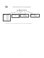
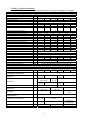
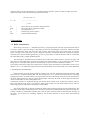
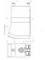
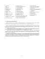
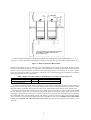
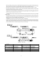
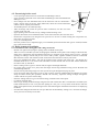
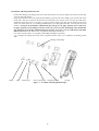
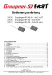
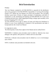
MANUAL
FOR ASSEMBLY OF BOILER
VIADRUS G 700
1
Dear Client:
We appreciate your confidence in our firm ŽDB a.s. Bohumín, Heating Technology
Plant VIADRUS and, we would like to thank you for purchasing Gas fired Boiler
VIADRUS GLADIATOR G 700.
In order to get used to a correct handling with Your new product, please kindly read
and get acquainted with a Guide for Use (primarily with the Chapter No.8 – Boiler
Attendance by User). We would appreciate if you could kindly adhere to the following
information and the Publication No. 91/93 Col. issued by the Czech High Authority on
Work Safety for ensuring the safe operation in the low temperature boiler rooms; this in
turn should ensure to you a trouble free operation of the boiler over many years, to yours
and our satisfaction.
Gas fired boiler VIADRUS G 700 was approved for operation in the Czech Republic:
by the following attest from the Machinery Testing Institute, State Testing Laboratory No.
202, Brno:
Certificate ES for Testing the style as per Standard ES 90/42/EHS
No. E – 37 – 00715
- 03
Certificate ES for Testing the style as per Standard ES 90/396/EHS
No. E – 37 – 00723
- 03
Certificate as per guidance 73/23/EHS
No. E – 37 – 00721 - 03
Certificate as per guidance 73/23/EHS
No. E – 30 – 00724 - 03
Certificate as per guidance 89/336/EHS
No. E – 37 – 00722 - 03
Certificate as per guidance 89/336/EHS
No. E – 30 – 00725 - 03
Certificate
No. B – 30 – 00726 - 03
2
Contents:
ORDER
4
1. BOILER USES AND ADVANTAGES
5
2. BOILER TECHNICAL PARAMETERS
6
3. DESCRIPTION
7
3.1. Boiler Construction
7
3.2. Placement and Installation
Table 3 Highest Allowable Limits for Heating Water as per ČSN 07 7401:1992 Code.
4. BOILER INSTALLATION
10
11
12
4.1. Boiler Body Installation
12
4.2. Pressurizing boiler vessel
14
4.3. Boiler Armature Installation
4.3.1. Installation of the closing plate and a flange for burner
14
14
5. BOILER JACKETING
17
6. ELECTRICAL PANEL – BASIC STYLING
18
7. BURNER INSTALLATION
19
8. GUARANTEE AND LIABILITY FOR DEFECTIVE GOODS
12
3
Order
Order Specification Code (type designation)
G 700 X X X X
Number of links:
10:
10 links
11:
11 links
12:
12 links
13:
13 links
14:
14 links
15:
15 links
Regulation Type:
4:
6:
OS 04
OS 06
Delivery status:
S:
assembled
R:
disassembled
Burner type:
0:
no burner
1:
with burner
In your order, it is necessary to specify parameters as per the requisite specification Code.
4
1. Boiler Uses and Advantages
Single-tier cast iron link hot water boiler with supercharged combustion chamber, direct heating is
designed for central heating on the basis of gaseous (natural gas) and liquid fuel (extra light heating Oil)
Supercharged burners used in combination with boiler must be designed to conform with:
ČSN EN 676 : 2000 – Gaseous fuel burners with ventilators and automatic regulation
ČSN EN 267 : 2000 – Liquid fuel burners with ventilators
ČSN EN 303-1:1999 – Boilers for central heating equipped with burners and ventilators
ČSN EN 303-2:1999 – Boilers for central heating equipped with burners and ventilators
ČSN EN 303-3:1999 – Boilers for central heating equipped with burners and ventilators
Boiler is manufactured exclusively for low pressure water systems of central heating, up to a maximum
operating temperature of heating water 90 deg C (optionally up to 115°C), minimum operating temperature of
heating water 60°C at maximumworking overpressure 4 bar.
The boiler vessel is tested at overpressure of 8 bar.
Advantages are:
1. high longevity of the cast-iron boiler body
2. Highly economical operation Over the whole power rating ranges, the fuel burning efficiency is higher than
91,5 % for all kind of fuels
3. As per wishes of the client, order supplied with burner
4. contemporary design
5. Fully automatic two step operation
6. Signalization during operation and failure announcement; signals could be eventually transferred to the
supervisory regulation system
7. Boiler could be controlled with aid of supervisory automatics or, space sensor of temperature
8. Depending on the boiler room disposition, closure plate opening could be towards left or right side
9. Easily accessible viewing glass and the probe for overpressure measurement in the combustion chamber
10. When used with burners recommended by the manufacturer (see Chapter “Boiler Technical Parameters”),
boilers of this sort are regardful of environment because the fuel combustion products strictly conform to the
demanding ecological standards and regulations.
5
2. Boiler Technical Parameters
Table 1 Thermo – technical Parameters of the Boiler (Fuel: Natural gas H, heating oil extra light)
Boiler size (number of links)
pc
10
Nominal power
Lower step Power
Power Intake range
Minimum efficiency
Range of temperatures regulation
Fuel consumption – natural gas
- diesel fuel, heating oil
kW
kW
kW
%
°C
m3/h
Kg/h
330
400
470
550
650
750
In accordance with a range of selected burner type
360
438
512
591
710
820
91,5
60 – 90 (optionally 115)
36,1
43,9
51,4
60,2
71,1
82,3
30,2
36,8
43,1
50,5
58
65,5
Fuel Mass flow
0,088
Combustion products temperature
Combustion products temperature I. Step
Combustion products routing volume
Depth of combustion chamber
Volume of combustion chamber
Heat transfer surface
Pressure loss on the combustion products side
Recommended smokestack draught
Volume of boiler water space
Kg/se
c
°C
°C
dm3
mm
dm3
m2
mbar
mbar
L
Pressure loss on the water side – dt = 20 K
- dt = 10 K
Stand by Loss
Maximum working overpressure
mbar
mbar
kW
bar
Dimensions - width
- height
- depth
Heat transfer media Connections
Diameter of the smoke exhaust sleeve
Burner flange (boiler part) – H70
Burner connection dimensions
mm
mm
mm
mm
mm
mm
mm
Boiler Mass
Kg
1660
1815
1970
2125
2280
2430
Boiler size (number of links)
Recommended Burners
NATURAL GAS, BIOGAS
pc
10
11
12
13
14
15
INTERCAL
BENTONE
WEISHAUPT
PBS Třebíč
DUNPHY
11
12
13
14
15
0,10
0,12
0,135
0,156
0,180
610
1377
314
21,35
0,9
676
1527
347
23,8
1,4
874
1977
447
31,14
5
940
2127
480
33,58
6,2
252
277
165 - 190
130
742
808
1677
1827
381
414
26,26
28,7
2,2
3,2
Min. 0,2
302
327
352
377
0,9
3,4
0,89
1,35
3,9
0,95
2,6
8,6
1,06
3,34
12,4
1,11
4,2
16,7
1,16
2442
2442
2592
1,9
5,3
1
4
904
1424
1842
2142
2142
100
250
300
220
Given in the documentation of the selected burner type
SGN
SGN 77/2
SGN
77/2-350
88/2
BG 450 2
BG 550
BG 650 – 2 (M)
BG 450 M
– 2 (M)
BG 450
BG 550 LN
BG 600
BG 700 LN
LN
LN
WG 40 N/1 - A
G 5/1 – D (LN)
APH-M 04 PZN,
APH-M 04 PZN,
PPN, PZ
PPN, PZ
TG05.100 HL
(MP)
Recommended Burners
LIQUID FUEL
INTERCAL (fa ESK Brno)
SL 77/2
SL 88/2
CUENOD (fa ESK Brno)
BENTONE
WEISHAUPT
B 45 A2.2
WL 40-A
6
B 55 – 2
L3 Z-A
CUENOD
C. 100 H 201
B 65 – 2
Gas flow data are for gas temperature of 0 °C and atmospheric pressure of 1013,25 mbar To adjust for actual
temperature and pressure, the following formula may be used.:
1013,25 . (273 + t)
V = VE .
----------------------------------------
p . 273
V
VE
t
p.
273
-
Gas volume at given pressure and temperature
Gas volume at 0°C and 1013,25 mbar
Gas temperature (°C)
Absolute gas pressure (mbar)
Absolute temperature (K)
3. Description
3.1. Boiler Construction
Boiler body (see Figure 1 – individual positions) is composed of links with aid of pressed inserts that are
secured by anchor bolts. The design of the boiler provides for three-draught construction, whereby the links
create the combustion space and convection part, inside is then actual water space of the boiler. To seal the
boiler, a sealing cord is placed into a groove along the perimeter of individual links and combustion chamber,
enforced by the silicone binder applied onto grooves in places where connection between links is created after
the whole boiler body is tightly bonded together.
The front link is furnished with an insulated closure plate that could be made to open left or right. This
must have corresponding hinges and closures installed. The burner flange is a part of the closure plate. On the
flange, there is a viewport with a probe for measuring the overpressure in the combustion chamber.
The opening φ 126 mm in upper part of front link is closed by means of a flange to accommodate a well, via predrilled 3 x G ½:“, for thermostat, safety thermostat and thermometer, and a return check valve of the manometer
.
φ 126 blanked by the blind flange..
Intake and take off of the heating media is situated on the rear link; furnished with flanges and sleeve DN
100 as well as a companion flanges DN 100. The draining tap G ¾“ is situated on the lower sleeve. The flange
equipped with sleeve for intake of heat carrying substance has also a delimiting insert part. On the casting above
the lower flange with sleeve, there is external ground safety contact for the boiler. In both, upper and lower part
of the rear link there are four cleaning dishcovers.
Combustion products are exhausted through the exhaust throat placed on the combustion products collector.
Below the exhaust throat, there is an explosive shutter with a holder. On the smoke exhaust sleeve, there are
measuring places for temperature and analyzer of the effluent.
The whole boiler body is perfectly insulated by plates made of mineral wool having 100 mm thickness. The
steel jacket of the boiler is hanged upon two consoles of the shroud, situated besides the upper anchoring bolts.
Surface treatment is performed by painting with comaxite paint. Electrical panel is situated in the front part of
the boiler, and it houses all switching, regulatory and security elements as well as their interconnecting
terminals.
7
8
Figure 1 – Boiler Assembly Dwg.
1. Front link
2. insert
3. Middle link
4. Rear link
5. Effluent collector
6. Cleaning lid
7. Sealing cord
8. Explosive shutter
9. closure
10. Insulated closure plate
11. hanger
12. Insulated burner plate
13. Viewport w. probe
14. flange 170x170 w. drillings
3x G1/2“
15. Electropanel console
16. Flange 170 x 170
17. Distributing pipe with sleeve
18. Return water flange
19. Companion flange
20. Heating water flange
21. Anchor bolts:
22. Jacket console
23. Connectors console
24. casing part left front
25. casing part right front
26. Side part of cover.
27. Side part of cover rear.
28. Front part of jacket portion 2. right
29. Front part of jacket portion 2. left
30. upper front part of the jacket
31. upper rear part of the jacket
32. Upper jacket part
33. Rear portion upper and lower
34. Rear part of cover middle
35. Draining tap
36. Return valve of thermomanometer
37. Thermostat wells and capillaries
Of thermometer
38. large blind
39. blind with a thermomanometer
40. Power module
41. Front jackef lid
42. Electrical panel lid
43. casing part front right
44. Process clock
3.2. Placement and Installation
Boiler VIADRUS G 700 is supplied in a disassembled state, i.e. individual links on palette, boiler armature
and auxiliaries in proper packaging container, jacket and insulation also in the packaging case.
Boiler is designed for placing in enclosed spaces having low up to middle aggressive environment; from the
point of view of electro-technical regulations the surroundings just ordinary (ČSN 33 2000 – 7 – 701:1997). It is
also suitable for use in spaces separated from the actual residential environs prostoru (Notice 91/93 Col.., ČSN
07 0703:1986 Gas Boiler Plants).
Boiler operates at noise level not exceeding level LA = 85 dB(A) (the actual magnitude depends on
the type of burner used: For the recommended types it ranges between 60 – 70 dB).
Boiler must be build on non-flammable liner or on a bedding about 50 mm high. A non-encumbered
space must be left in front of the boiler to allow manipulations, this must be the depth of the boiler + 500 mm
minimum, from the side 600 mm (to allow access to the rear), in the back 800 mm and between two boilers a
space of 500 mm should be kept.
Above all for boiler placement it is necessary to respect the disposition requirements for selected type
of the burner (gas intake, etc.) The space distance L in front of the boiler as per the following figure, is
specified for case of cleaning the boiler by mechanical brush. If the clean up maintenance is to be done by
chemical means, the distance dependes again on the type of selected burner.
10
Je nutné respektovat dispoziční požadavky zvoleného typu hořáku (přívod plynu, délka hořáku, etc.) – It is
necessary to respect placement requirements according to selected burner type (gas inlet, length of burner, etc.)
Figure 2 – Boiler Placement in Boiler Room
Filling of the heating system by water First, the whole heating system must be thoroughly flushed to cause
removal of all impurities that may be deposited in the distributions or heating bodies and could subsequently
become a source of pump damage. To fill the boiler and heating system, it is necessary to use clear, colorless
water, free from foreign matter in suspension, without any oil or chemically aggressive substances. Circulating
and replenishing water must correspond to:
Table 3 Highest Allowable Limits for Heating Water as per ČSN 07 7401:1992 Code.
Hardness
Ca2+
Total concentration of Fe + Mn
*) recommended value
mmol/L
mmol/L
mg/L
1
0,3
3*
In case the hardness be outside of the specifications, water must be conditioned.. Experience shows that even
multiple reheat of the hard water will not prevent deposition of salts on interior surfaces of the boiler vessel.
Deposits of about 1 mm thick (limestone) will cause a loss of heat transfer from metal to water of about 10%.
During the heating season, a stable level of water volume in the system must be ensured while being mindful
that the heating system must be periodically de-aerated. Boiler and heating system water must never be
discharged or bled from the system save for urgent and necessary situations such as maintenance, etc. Bleeding
the conditioned water from the heating system and refilling it with new water is always associated with danger
of an increased corrosion and calcite deposit formation. Should it be necessary to refill the water in the heating
system, it is permitted only when the boiler is let to cool; this will prevent a potential crack failure of castiron links.
11
4. Boiler Installation
4.1. Boiler Body Installation
List of parts needed
− Boiler links front, rear, and appropriate number of middle
− Requisite number of boiler inserts
− Sealing cord (appx. 6m/link)
− Anchor bolts: 4 pc w. gussets
− Oil paint for painting boiler inserts
− Bolt with an eye 4 pc
− Flange 170x170 w. drillings 3xG ½”
− Flange 170x170 blind 3
− Well of capillary thermometer
− Well for I. and II. Step boiler thermostats
And security
− Checkvalve of manometer
− Silicone sealant/binder (from
manufacturer)
− Flange of heating water with
sleeve
− Flange of return water with sleeve
− Distribution pipe
− Companion flange 2 pc
10
8
18
53
1480
11
9
20
59
1630
Links number
12
13
10
11
22
24
65
71
1780 1930
14
12
26
77
2080
15
13
28
83
2230
Figure 3
Rear link
Distributor pipe
adapter
Middle link with
insert
Front link
flange 170x170 w.
drilling
and seals
Flange 170x170
Blind w. seal
Installation procedure
− Boiler is to be built on a horizontal bedding
− Position the rear link on the bedding and using suitable brace, support it
− Drilled openings of the insert holes in rear link should be thoroughly cleaned to remove remnants of
conservation agent and impurities
12
− Insert the sealing cord into grooves of individual links (except the front one) Tap the cord into the groove,
where the joint is there must not be any space left For middle link that is bonded last, do not place the cord to
grooves on four travers columns – the front link does not have in this location the sealing rib
− Outer edges of the said holes to be dulled by cabinet file, then paint the openings by oil paint or varnish
− Put inserts already painted by oil paint or varnish, into the appropriate openings and tap by using wooden
mallet Insert must be properly and evenly put through
− Put the link over the protruding parts of the inserts in such a way that the inserts edge in easily into the link
openings for inserts, tap in place by wooden mallet and using bonding tools, bind together Link is in a
position facing the sealing rib towards the rear link.
CAUTION: Ensure that the spacing between individual links remains during the whole process of binding
together equal!
− During bonding, the sealing rib of one link presses into the cord located in the groove of the other link Links
are properly seated when they sit in parts containing sleeves well together (above and from the bottom of
boiler body) and, along the perimeter an uniform groove is formed allowing the sealing binder application.
Repeat the process to carry out binding of all remaining links
CAUTION: To bind at any one time more than one link is not permitted!
− Locate the anchor bolts on the boiler vessel such that the longer thread shows towards the front and, the front
end does not protrude beyond the casting more than 20 mm Affixing of the individual parts that belong to the
anchor bolting, during the binding of the boiler body, is observable from Fig. 4 (detail X and Y) Binding
pressure should be such as to compress the gussets to about 32 mm length.
Figure 4 – Anchor Bolt
LEGEND:
Horni kotelni sroub
Nalitek na prednim
clanku pro kotevni sroub
Nalitek na zadnim clanku
pro kotevni sroub
pruzina
konzola
Sroub s okem
Upper anchor bolt
Front link lug for
anchoring bolt
Rear link lug for
anchoring bolt
Lock spring
console
Bolt with an eye
Dolni kotevni sroub
Nalitek na prednim
clanku pro kotevni sroub
Nalitek na zadnim clanku
pro kotevni sroub
pruzina
Kotevni sroub
13
Lower anchor bolt
Front link lug for
anchoring bolt
Rear link lug for
anchoring bolt
spring
Anchoring bolt
4.2. Pressurizing boiler vessel
− Lower opening of front link to be closed with a blind flange 170x170
− Upper opening of front link to be closed with a blind flange 170x170 furnished with
drillings 3 x G ½ ”
− Screw flanges into the individual holes Of the three-seat well for: thermostats –
boiler I. and II. Power level step, safety thermostat, check valve of the manometer
and the well for capillary thermometer.
− All threaded joints to be sealed by hemp
− Affix the flange with socket for pressure water connection, into the rear lower
opening of the rear link.
Fig. 5.
− Upper opening of the rear link close by a flange with de-aerating valve
− Open the de-aeration valve and fill the boiler vessel with cold water, then close the valve.
− Perform the overpressure test using the 8 bar pressure over at least 15 minut. During the overpressure test,
there must not appear any leaks
− Carry out visual inspection
− Once the pressure test is completed, apply over individual joints between the links (groves created) a liberal
layer of the silicon binder.
4.3. Boiler Armature Installation
4.3.1. Installation of the closing plate and a flange for burner
− Decide over right or left styling for opening of the insulated closure plate
− Affix two screws with M16 eye hook for hanging the insulated closure plate to side castings of the front link,
either left or right Ensure the axial distance between eye centerline to the casting wall is 55 mm. - through
openings in side lugs of front link put two screws with eye M16, together without screwed on counternuts
M16 from the exterior side of the front link. Secure them from the interior side, by nuts M 16.
− Screw two threaded rods M16 x 130 into lug located on the ooposite side of the link – put through two
threaded shanks M 16 x 130 with counter nuts M16 from the external side of front link. Secure them from
the interior side, by nuts M 16.
− Place a sealing cord in a groove on front link, having φ12 and length 4860 mm
− On proper places on the cover plate, affix the hinges and closing mechanism using screws M10x40 with
internal hexagonal hole.
− Seat the closure plate using hinges over the eye bolts and, put through 16x60 pegs in place.
− Close the closure plate and secure by M 16 nuts in places of breech. Doublecheck the tightness of closure
along the whole closure plate perimeter. Should it be necessary, adjust the seating of hinges through the
counter nuts M 16 in places of breeching
− Place the sealing cord into a grove for burner flange, situated on the closure plate
− ¯ 10 about 1410 mm long
− Fasten up by bolting the burner flange using the bolts with internal hex M16 x 40 (thread to be sealed by the
binder brand Siseal) in such a way that the opening for view port is on top If the client did not order the
flange with requisite holes, the mounting must be done following the installation instructions accompanying
the burner
− Into the burner flange hole install the view port that must be furnished by sealing ∅ 78 / 44 below the flange.
View port to be secured by screws M4.
14
− Burner
closure
insulation
−
−
−
− washer
− Closure plate
burner flange insulation
− closure
− hanger
− Burner flange
−
Figure 6 – Burner Closure Clack Assembly
viewport
with seal
port lid
Installation of cleaning lids
− Place the sealing cord 10 into a groove of a rear link, located at four cleaning lids. For one groove, the cord
length of 760 mm.
− Place lids on studs and secure by nuts and washers
− keeping an eye on tight closing.
−
− Cleaning
lid
Figure 7 – Cleaning Lids
Installation of the Combustion products Collector and the
Smokestack Collar
−
−
−
−
Position the sealing cord 10 – 2390 mm into a groove situated on the rear link
Position the body of the effluent collector over the studs, and secure by nuts,
keeping an eye on tight closing.
Place the sealing cord into groove in the effluent collector towards the smokestack Collar
¯ 10 - 945mm
− Smoke stack exhaust sleeve ∅ 250 or ∅ 300 mm to be positioned on the collector and secured by bolts M
10x35
− Inspect the position for correct placement of the explosive clack on the effluent collector (leaktightness).
Figure 8 – Smoke Exhaust Assembly
− Exhaust
sleeve
−
− Explosive
closure
hanger
−
− Explosive
closure
Combustion
products
collector
15
Installation of Heating Media Takeoffs
− Position the heating water flange with sleeve DN 100 and seals over the top flange joint of the rear link and,
secure by nuts and washers
− Using open end first, insert the partitioning distribution pipe into the lower flange joint in front link of the
boiler body. The groove must be directed up. From the boiler rear, seat the sleeve over the open end of the
distribution pipe with screw in the sleeve, in upper position Apply seals and, seat the flange of the return
water over studs (socket G ¾” for filling and draining tap is on the right hand side), secure by four nuts and
washers. As long as the installation (distribution pipe with groove in upper position, sleeve with screw
in upper position, seals and flange of return water), the correct accurate positioning of the distribution
pipe should be ensured, thus aimed distribution of return water into every one of the boiler body links
will be secured. Once the boiler is hot, re-tighten all the flange connections.
− Over these existing outlets, it is possible to add additional flanges in between.
− 2 pc of flanges for heating and return water, supplied with the order, are to welded to the heating system
inlet.
Heating water flange
flange
seal
draining tap
return water flange companion flange
rear link
Figure 9 – Assembly of Heating Media Flanges
16
5. Boiler Jacketing
− Using bolts with an eye on anchoring bolts place the jacket console on front and rear link risers (longer
console end in the direction of front link)
− In all front pieces are to be screwed into riveted nuts in the top part pegs M5
− In side jacketing pieces left and right – opening diam. 8 mm in the top part of the side bend are to be inserted
with 2 pegs M5 with nut and washer, in the top part by 2 pegs M5
− Individual side pieces with insulation are fixed together with the use of connecting consoles (2 pc for 10
links version, 4 pc for 11, 12 and 15 links version, 6 pc for 13 and 14 links versions) that are from one side at
the bottom affixed by M5 screw
− Onto a console and concurrently on bottom anchoring bolt are to be pit side jacketing pieces left and right
− Similarly, side jacketing piece to be put on (2 pc for 11 and 12 links versions, 4 pc for 13 and 14 links
versions) from left and right in a way that the piece will be inserted into connecting console located at the
bottom part of previously installed part
− Similarly, rear side jacketing piece to be put on (2 pc for 11, 12, 13 and 14 links versions, 4 pc for 15 links
version) from left and right in a way that the piece will be inserted into connecting console located at the
bottom part of previously installed part
− Rear top jacketing pieces, bottom and middle are to be screwed together with side pieces using screws 4.2 x
9.5
− side pieces of jacketing and front piece 2 left and right are to be equipped by 3 pc of shape plugs in front and
at the top by 2 pc of pegs
− The pieces then are to be screwed together with corresponding side pieces of jacketing using screws 4.2 x
9.5
− Top rear piece of jacketing with insulation (1 pc for 10, 11, 12, 13 and 14 links versions and 2 pc for 15 links
version) insert onto the pegs in rear side jacketing pieces
− Top piece of jacketing with insulation (1 pc for 11 and 12 links versions and 2 pc for 14 and 14 links
versions) insert onto the pegs in side jacketing pieces
− Electrical panel console with 15 mm insulation on the top part of the panel is to be inserted onto screws with
nuts used for screwing together with 4-edged flange 170x170 with drilled opening 3 x G ½ “ to the front link
and secure with M16 nuts
− Dismount the electrical panel top lid and attach it using 2 screws M5 to the electrical panel console
− Front jacketing piece with 6 shape plugs insert into shape springs in corresponding places of the side front
pieces of the jacketing
− Left front jacketing part is to be equipped by 6 shape springs
− Right front jacketing part to be equipped by 3 shape springs and into the riveted nuts inserted also 3 shape
springs
− Front right and left jacketing pieces are to be inserted onto shape springs in the corresponding side jacketing
pieces front part 2
− Adjust the location of electrical panel so as the facing side would be in line with front jacketing part
− Cover again the electrical panel and put on the lid
17
Top jacketing piece top jacketing piece top jacketing piece jacketing console console
electrical panel lid
jacketing piece
Rear
front
of the electrical panel
upper rear part of
the jacket
electrical panel front
pravý
Side part of cover
rear.
Rear part of cover
middle
jacketing piece left
front – part 2
Rear bottom part of
the jacketing
Side part of cover.
Connectors console
Front left side part
of the jacketing
Left front part of jacketing
side piece of jacketing side piece of
jacketing
Figure 10 – Boiler Jachet – Exploded View
6. Electrical Panel – Basic Styling
Main power
switch
Heating water
temperature
exceeding signalling
Burner malfunction
signalling
Fuse 10 A
Blinds
(plugs)
Thermomanometer
Blind (plug)
Regulatory
Thermostat I.
step
Safety
thermostat
Regulatory Thermostat II.
-Operating hours I. and II. Step metering
step
devices
Figure 11 – Electro-panel Scheme
18
Electrical panel is composed of the following basic parts :
-
Electrical panel with power network module
Capillary manometer
Capillary thermometer
Regulatory Thermostat I. step
Regulatory Thermostat I. step
Safety thermostat
Operating hours I. and II. Step metering devices
control lights indicating operation in mode I and II of the burner
Signal light “failure” indicating a contact actuation on safety thermostat
connector terminal
“In case the client requires an isothermal regulation is User manual for operating and
installation part of the supplied order”
7. Burner Installation
− Installation of the burner, setting it properly and commissioning the boiler into operation must be entrusted to
the burner supplier’s authorized service organization
− The service organization is obliged to train the operating personnel in operation, pass on them the
appropriate manual for manipulation with the burners and, to secure carrying out warranty as well as postwarranty service and repairs
− In case that the burner connection to the fuel supply main is occasioned using flexible feeding lines, the main
fuel closure valve must be installed on the end of the fixed piping, before the flexible elements are mounted.
− Burner Noise level complies with the ČSN 07 5801:1990 Sec. 78, meaning the measured values in all
operating regimes are below the limiting value of noise LA - 85 dB (A) (actual value depends on the type of
used burner : For the recommended types it ranges between 60 – 70 dB).
19
8. Guarantee and Liability for Defective Goods
The manufacturer of the Equipment VIADRUS provides a guarantee for:
– Boiler for a duration of 24 months from the date of sale to the final user
– Boiler body for 5 years following the date of expedition from the manufacturing plant
To maintain the validity of the guarantee undertaking, the manufacturer requests:
– In compliance to the Code 222/94 Col.o.L. „O podmínkách podnikání a o výkonu státní správy
v certifikovaných odvětvích a o Státní energetické inspekci“ = „On business conditions and
government supervision in the certified branches and State Inspections“, and ČSN 91 93, ČSN 07
0703 : “Czech Highest Authority for the Labor Safety and for Assuring Work Safety in the Low
pressure Boiler rooms”, and ČSN 38 6405, ČSN EN 1775 to carry on regular inspections of the boiler.
All controls to be carried out exclusively by authorized service organization (contractual service),
accredited by the manufacturer ŽDB a.s. Bohumín, Závod topenářské techniky VIADRUS and, by the
manufacturer of the burning devices.
– Keep thorough records of all warranty and post-warranty repairs performed as well as a record of all regular
annual inspections of the boiler – these to be marked on the attachment to the warranty certificate – an
integral part of the revision record book of the boiler.
Guarantee will not be honoured when:
- Faults exist as a result of faulty installation and incorrect operating of the product
- Damage to the product during transport or due to other type of mechanical damage outside of the
plant
Faults due to improper warehousing
All reports of faults must be done immediately after their occurrence and always in writing
Unless the above directives are strictly adhered to, the guarantee extended by the manufacturer shall not
be honoured.
Manufacturer reserves the rights to changes made in the context of product innovation; these might not
be included in this Manual hereto presented.
.
21
21
1 – front link
4 – rear link
7 – explosive shutter holder
10 – closure plate
13 – burner plate
threading
16 – electric panel console
19 – distributing pipe
22 – anchoring screw
25 – side portion of the jacket
28 - well
jacket
31 – insulation upper part
insulation
34 – rear portion of the cover
middle
38 – electrical panel
jacket
41 – side part insulation
44 – insulation over rear side part
part
47 – side part left
50 – casing part front right
2 - insert
5 – combustion effluent collector
8 – explosive shutter
11 - hanger
14 – viewport set
3 – middle link
6 – cleaning dish-covers
9 - closure
12 – insulation matter
13 – flanges with
17- seals
20 – flange for heating water
23 – console with cable trough
26 – smoke draught sleeve
29 – electrical panel cover
18 – blind flange
21 – companion flange
24 – connectors console
27 – valve of manostat
30 – upper portion rear
32 – upper front part of the jacket
33 – upper jacket cover
35 – insulation over rear upper part
36 – rear portion jacket
39 – side part insulation
40 – side portion of the
42 – side part right front
45 – upper rear part of the jacket
43 – side part rear jacket
46 – insulation rear upper
48 – side part right
49 – casing part left front
Figure 12 – Boiler Assembly
Revision Date: 48th week 2005
21
Number of links:
10:
10 links
11:
11 links
12:
12 links
13:
13 links
14:
14 links
15:
15 linksRegulation Type:
4:
6:
OS 04
OS 06
Delivery status:
S:
assembled
R:
disassembled
Burner type:
0:
no burner
1:
with burner1. Front link
2. insert
3. Middle link
4. Rear link
5. Effluent collector
6. Cleaning lid
7. Sealing cord
8. Explosive shutter
9. closure
10. Insulated closure plate
11. hanger
12. Insulated burner plate
13. Viewport w. probe
14. flange 170x170 w. drillings
3x G1/2“
15. Electropanel console
16. Flange 170 x 170
17. Distributing pipe with sleeve
18. Return water flange
19. Companion flange
20. Heating water flange
21. Anchor bolts:
22. Jacket console
23. Connectors console
24. casing part left front
25. casing part right front
26. Side part of cover.
27. Side part of cover rear.
28. Front part of jacket portion 2. right
29. Front part of jacket portion 2. left
30. upper front part of the jacket
31. upper rear part of the jacket
32. Upper jacket part
33. Rear portion upper and lower
34. Rear part of cover middle
35. Draining tap
36. Return valve of thermomanometer
37. Thermostat wells and capillaries
Of thermometer
38. large blind
39. blind with a thermomanometer
40. Power module
41. Front jackef lid
21
42. Electrical panel lid
43. casing part front right
44. Process clock
Rear link
Distributor pipe
adapter
Middle link with insert
Front link
flange 170x170 w. drilling
and seals
Flange 170x170
Blind w. seal
− Burner closure insulation
−
−
−
− washer
− hanger
− Closure plate
burner flange insulation
− closure
uzávěr
− Burner flange
−
viewport
with seal
uzávěr
− Exhaust sleeve
−
− Explosive closure hanger
−
− Explosive closure
Combustion products collector
flange
seal
draining tap
port lid
return water flange companion flange
Top jacketing piece top jacketing piece top jacketing piece jacketing console
panel front jacketing piece
21
console
rear link
electrical panel lid
electrical
Rear
front
of the electrical panel
pravý
upper rear part of the jacket
Side part of cover rear.
Rear part of cover middle
jacketing piece left front – part 2
Rear bottom part of the jacketing
Side part of cover.
Connectors console
Front left side part of the jacketing
Left front part of jacketing
side piece of jacketing side piece of jacketing
front right
front right part 2
21
Heating water temperature exceeding signalling
Burner malfunction signalling
Fuse 10 A
Blinds (plugsThermomanometer
Regulatory Thermostat II. step
Operating hours I. and II. Step metering devices
Main power switch
Blind (plug)
Regulatory Thermostat I. step
Safety thermostat
21