1
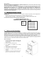
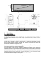
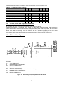
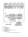
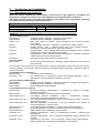
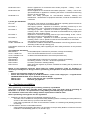
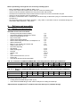
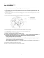
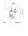
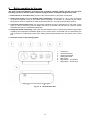
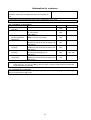
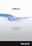
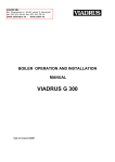
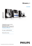
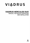
VIADRUS HERCULES U 22 P/N
Manual for boiler operation and installation
GB_2014_36
Table of contents:
page
1.
Manufactured boiler variants......................................................................................................................3
2.
Boiler use and advantages ........................................................................................................................3
3.
Technical data of boilers ............................................................................................................................4
4.
Description .................................................................................................................................................5
4.1
Boiler construction ..............................................................................................................................5
4.2
Control, safety and regulation elements .............................................................................................7
4.3
Boilers wiring diagrams ......................................................................................................................7
5.
Positioning and installation ........................................................................................................................9
5.1
Regulations and quidelines ................................................................................................................9
5.2
Positioning possibilities ................................................................................................................... 10
6.
Delivery and assembly ............................................................................................................................ 12
6.1
Delivery and accessories ................................................................................................................ 12
6.2
Assembly procedure ........................................................................................................................ 13
7.
Commissioning........................................................................................................................................ 16
7.1
Verification before commissioning................................................................................................... 16
7.2
Boilers commissioning ..................................................................................................................... 16
7.3
Boiler conversion from “gaseous or liquid fuels“ to the „solid fuels“ and vice versa ....................... 16
8.
Boiler operation by the user .................................................................................................................... 17
9.
Maintenance............................................................................................................................................ 18
10.
Defects and their elimination ............................................................................................................... 18
11.
IMPORTANT WARNINGS ................................................................................................................... 19
12.
Instructions for product disposal after its service life ........................................................................... 20
13.
Guarantee and liability for defects ....................................................................................................... 20
2
Dear customer,
We thank you that you have bought the VIADRUS HERCULES U 22 universal boiler thus having
shown your confidence in VIADRUS a.s.
For you to get used to a correct way of handling your new product from the beginning please read at
first this manual for its usage (first of all the chapter no. 8 – Boiler operation by user, chapter no. 9 –
Maintenance and chapter no. 11 – Important warnings). Please follow the undermentioned
information and especially those regarding the prescribed annual controls to be done by an
authorized specialised firm, whereby a long-time and trouble-free boiler operation will be guaranteed
to both your and our satisfaction.
1.
Manufactured boiler variants
VIADRUS HERCULES U 22 boiler is a universal cast-iron sectional low-pressure boiler designated for
combustion of:
- Gaseous fuels (natural gas) and its brand name is VIADRUS HERCULES U 22 P
- Liquid fuels (fuel oil extra light – TOEL) and its brand name is VIADRUS HERCULES U 22 N
In the purchase order you must specify the following data:
Purchase order specification code
VIADRUS HERCULES U 22 X X
Fuel:
P: gas
N: oil
2.
Number of sections:
3: 3 sectional design
4: 4 sectional design
5: 5 sectional design
6: 6 sectional design
7: 7 sectional design
8: 8 sectional design
9: 9 sectional design
0: 10 sectional design
Boiler use and advantages
The boiler design you have received is designated for combustion of gaseous fuels and its brand name is
VIADRUS HERCULES U 22 P and for combustion of liquids fuels and its brand name is VIADRUS
HERCULES U 22 N. The three-sectional size is suitable for heat sources reconstruction in smaller houses
and leisure amenities. Bigger sizes comply with demands on heating the houses, shops, schools etc.
The boiler is only made as a warm-water unit with natural and forced heating water circulation and working
overpressure up to 400 kPa (4 bar). Before despatch the boiler is tested for tightness by applying 800 kPa
(8 bar) test pressure; it stands the insulation and contact resistance tests.
Boiler advantages:
1. A long service life of cast-iron exchanger and
all other parts with regard to the quality of
used materials.
2. Efficiency of gas combustion 89 %.
3. The reliability of regulation and security
elements.
4. Simple operation and maintenance.
5. Low demand on chimney draught..
6. Graduation of output by the number of
sections.
7. Possibility to convert the solid fuels boiler to
gaseous or liquid fuels boilers or vice-versa.
3
3.
Technical data of boilers
Tab. no. 1 Dimensions, technical parameters and electric values of boiler
Fuel efficiency: natural gas 33,99 MJ/kg
fuel oil extra light (TOEL) 42,7 MJ/kg
Number of sections
Weight
Water space volume
Diameter of smoke socket
Boiler dimensions: - height incl. OS 03 x width
- depth L
Volume: - of combustion chamber
- of fume ducts
Combustion gas volume
Water working overpressure
Water test overpressure
pc
kg
l
mm
mm
mm
3
m
3
m
3
m
kPa
(bar)
kPa
(bar)
-
3
218
31,5
4
252
36,2
5
282
40,9
434
0,037
0,028
0,065
530
0,046
0,063
0,109
626
0,058
0,08
0,138
6
312
45,6
7
8
347
377
50,3
55,0
156
1008 x 520
722
818
914
0,069 0,080 0,092
0,097 0,114 0,131
0,166 0,194 0,223
400
(4)
800
(8)
see.Fig.. no. 1
9
417
59,7
10
448
64,4
1010
0,104
0,148
0,252
1106
0,115
0,165
0,280
Pressure loss
Recommended heating water operating
°C
60 – 80
temperature
Noise level
dB
Does not exceed the level 65 dB (A)
Chimney draught
mbar
Min. 0,05
Tensile loss
mbar
0,17
0,21
0,24
0,28
0,31
0,36
0,39
Overpressure in the combustion chamber
mbar
0,01
0,03
0,05
0,08
0,11
0,14
0,17
Boiler connections – heating water
DN 50
– return water
DN 50
Connecting voltage
1/N/PE 230 V AC 50 Hz TN - S
Electric input
kW
Max. 0,1
Electric coverage
IP 40
Environment
basic AA5/AB5 ČSN 33 2000-1 ed. 2
The values independent on the type of used central burner are shown in burner documentation.
0,43
0,2
Tab. no. 2 Thermal-technical parameters of boiler designated for natural gas combustion
-3
(Fuel efficiency 33,99 MJ.m , air temperature 15 °C and bar. air pressure 1013,25 mbar)
Number of sections
Appliance category
Output
Input
Standby loss
Efficiency
Combustion products weight 9,5% CO2
Combustion products temperature
Fuel connecting overpressure
pc
3
4
5
6
7
8
9
10
40,7
46,5
0,36
46,5
52,8
0,39
52,3
59,4
0,42
58,1
66
0,44
88,2
99,2
110
I 2H
kW
kW
kW
%
-1
kg.hod
°C
mbar
17,7
20.11
0,23
23,3
26.5
0,26
29,1
33
0,30
33,5
44,1
55,2
34,9
39,6
0,33
89
66,1
77,2
Max. 240
18
Tab. no. 3 Thermal-technical parameters of boiler designated for combustion of fuel oil extra light
(TOEL)
-1
(Fuel efficiency 42,7 MJ.kg , air temperature 15 °C and bar. air pressure 1013,25 mbar)
Number of sections
Output
Input
Standby loss
Efficiency
Combustion products weight 13% CO2
Combustion products temperature
Fuel connecting overpressure
pc
kW
kW
kW
%
-1
kg.hod
°C
mbar
3
17,7
19.9
0,23
4
23,3
26.1
0,26
5
29,1
32,7
0,30
6
34,9
39,2
0,33
7
40,7
45,7
0,36
8
46,5
52,2
0,39
9
52,3
58,8
0,42
10
58,1
65,3
0,44
89
59,6
69,4
79,3
89,3
99,2
Max. 240
According to the boiler manufacturer ´s recommendation
30,2
4
39,6
49,7
300
250
Pa
Pressure loss
200
150
100
50
0
15
20
25
30
35
Fig. no. 1
Number of sections
L (mm)
3
434
Fig. no. 2
4.
Description
4.1
Boiler construction
4
530
40
45
50
6
722
60
Output in kW
Pressure loss
5
626
55
7
818
8
914
9
1010
10
1106
Boiler main dimensions
The main part of boiler is the cast-iron sectional boiler drum made of grey cast iron according to
ČSN 42 2415 or ČSN 42 2420.
The pressure parts of the boiler correspond to the strength requirements according to EN 297, EN 303-1,
EN 303-2.
VIADRUS HERCULES U 22 boiler has a cast-iron closed overpressure combustion chamber. This is a boiler
with three draughts.
The boiler drum is assembled of sections by means of forced on insertions and tightened with the anchor
bolts. The sections create the combustion space, the water space and the convective part. Heating water
input and output are situated in the rear part of boiler.
The rear section of boiler in its upper part has a smoke extension and a heating water flange, in the lower
part a return water flange with a mouthpiece for draining and filling taps.
To the front section there are mounted closing plates serving for an easy boiler maintenance. The lower
closing plate is prepared for the pressure burner assembly.
For a better utilization of heat contained in combustion products there is installed a partition separating the
combustion products flow in the boiler drum. In the rear part of boiler there is placed a fireclay shaped piece
for protection of boiler drum against unwanted thermal effects. In case of 7-10 sectional version there are
used two kinds of central sections: in the front part of the boiler the sections are without the strip, in the rear
part of boiler they are with the strip. The strip closes the combustion chamber and returns the flame and
combustion products from the rear space into the front part it means through a return way in smoke draughts
the combustion products temperature is perfectly utilized.
Numbers of sections without a strip and with a strip are shown in table as follows:
5
Tab. no. 4 Central sections of boilers
Boiler size in number of sections
2
Central section with a strip
Central section without a strip
-
1.
2.
3.
4.
5.
6.
7.
8.
9.
10.
3
1
-
4
2
-
Boiler drum
Rear Fire-clay shaped piece
Combustion section partition
Fire-clay fillet 166
Combustion space partition right
Combustion space partition left
Closing plate - upper
Closing plate –lower
Smoke extension
Sealing
11.
12.
13.
14.
15.
16.
17.
18.
19.
20.
5
3
-
6
4
-
7
4
1
8
5
1
9
5
2
10
6
2
Heating water flange
Return water flange
Filling and draining tap
Well G ½“
Check valve for the manometer
Boiler shell with insulation
Closing lid
Plug
Clip MEOS
Control box OS 03
Fig. No. 3 Diagram of boilers
In the upper part of the rear section there is installed a clack-valve of thermo-manometer and a reservoir for
thermostat and thermometer sensors. In the lower part of smoke extension there is installed a cleaning
cover. The explosive flap belongs to the lower closing plate. The burner connection to fuel supply and
refilling is done according to the instructions stated in burner documentation.
The whole boiler drum is insulated with health harmless insulation which reduces losses related to heat
transfer into environment.
6
The boiler steel shell surface is painted by using a good quality coloured comaxite paint.
Tab. no. 5 Combustion space partitions
number of sections
3
Combustion section partition
Tab. no. 6 Fire-clay lining
number of sections
Rear Fire-clay shaped piece
Fire-clay shaped piece of covering
plate
Fire-clay fillet 160 x 123 x 20
Fire-clay fillet 83 x 12 x 20
Fire-clay fillet 250 x 123 x 20
4.2
4
1
5
1
6
2
7
2
8
3
9
3
10
3
3
1
1
4
1
1
5
1
1
6
1
1
7
1
1
8
1
1
9
1
1
10
1
1
-
2
-
2
-
2
2
2
2
2
4
2
4
Control, safety and regulation elements
All regulation and safety elements are situated in OS 03 control electric box.
The thermomanometer, a compound gauge serves for outlet water temperature and water pressure in
system determination, the thermostat serves for setting the heating water outlet temperature, the main switch
serves for switching on the boiler to get started. The burner defect is signalled by lighting up the LED called
“burner fault”. Boiler overheating above the safe limit 90 °C is signalled by lighting up the LED called
„overheated“ a at the same time the safety thermostat is blocked (if the boiler burner switches off).
4.3
Boilers wiring diagrams
ϑ
ϑ
ϑ
LEGEND:
S1
MAIN SWITCH
H1
„ON“ SIGNALLING
Z1
SUPPRESSION COMPONENT
BT1
SAFETY THERMOSTAT
H2
BT1 SIGNALLING
BT2
SERVICE THERMOSTAT
BT4
ROOM THERMOSTAT (BOILER OUTSIDE CONTROL)
H3
BURNER DEFECT SIGNALLING
X1
TERMINAL BOARD
X10
BOILER CONNECTOR
Fig.no. 4
Elementary wiring diagram of with OS 03 box
7
(OUTSIDE CONTROL)
OUTSIDE CONTROL
(OUTSIDE
CONTROL)
ϑ
ϑ
BOX
LEGEND:
S1
MAIN SWITCH
H1
„ON“ SIGNALLING
Z1
SUPPRESSION COMPONENT
BT1
SAFETY THERMOSTAT
H2
BT1 SIGNALLING
BT2
SERVICE THERMOSTAT
BT4
ROOM THERMOSTAT (BOILER OUTSIDE CONTROL)
H3
BURNER DEFECT SIGNALLING
X1
TERMINAL BOARD
X10
BOILER CONNECTOR
Fig.no. 5
Elementary wiring diagram of with OS 03 boxes
8
5.
Positioning and installation
5.1
Regulations and quidelines
Boiler can only be installed by a firm holding a valid license for gas appliances installation and
maintenance. A project according to the valid regulations must be prepared for installation.
The heating system must be filled with water, that meets the ČSN 07 7401 requirements, especially
its harness must not exceed the required parameters.
Hardness
2+
Ca
Concentration of total Fe + Mn
Recommended values
mmol/l
mmol/l
mg/l
1
0,3
(0,3)*
*) recommended value
WARNING!!! The use of anti-freeze mixture is not recommended by the manufacturer.
a) to the heating system
ČSN 06 0310
ČSN 06 0830
ČSN 07 7401
EN 267
EN 303-1
EN 303-2
EN 303-3
EN 676+A2
b) to the chimney
ČSN 73 4201
Heating systems in buildings – Designing and installation
Heating systems in buildings – protecting device
Water and steam for thermal energy equipments with working pressure
up to 8 MPa.
Forced draught oil burners – Definitions, requirements, testing, marking.
Heating boilers - Part 1: Heating boilers with forced draught burners Terminology, general requirements, testing and marking
Heating boilers - Part 2: Heating boilers with forced draught burners - Special
requirements for boilers with atomizing oil burners.
Heating boilers - Part 3: Gas-fired central heating boilers - Assembly comprising
a boiler body and a forced draught burner
Automatic forced draught burners for gaseous fuels.
Chimneys and flue gas ducting– designing, implementation and connection of
fuel consumers.
The connection must carried out only if approved by a chimney organization wand must meet all provisions
of these standards. The chimney must be resistant to combustion gases condensate, otherwise it might be
seriously damaged.
c) regarding the fire regulations
ČSN 06 1008
Fire safety of heat installations.
EN 13501-1 +A1
Fire classification of construction products and building elements – Part 1:
Classification using test data from reaction to fire tests
d) to the system of HWS heating
ČSN 06 0320
Heating systems in buildings – Hot water preparation – Designing and planning
ČSN 06 0830
Heating systems in buildings – Safety devices.
ČSN 75 5409
Water installations inside buildings.
e) regarding the electric network
CSN 33 0165
Electrical regulations. Identification of conductors by colours or numerals.
Procedure provisions
ČSN 33 1500
Electrical regulations; revision of electrical equipments
ČSN 33 2000-1 ed. 2
Low-voltage electrical installations – Part 1: Fundamental principles,
assessment of general characteristics, definitions.
ČSN 33 2000-4-41 ed. 2
Low voltage electrical installations - Part 4- 41: Protection for safety - Protection
against electric shock
ČSN 33 2000-5-51 ed. 3
Electrical installations of buildings – Part 5-51: Selection and erection of
electrical equipment – Common rules
ČSN 33 2130 ed. 2
Low-voltage electrical installations – Internal electric distribution lines
ČSN 33 2180
Electrical regulations: Connection of electric instruments and appliances
ČSN 34 0350 ed. 2
Safety requirements for flexibile cords and cables
EN 60079-10-1
Explosive atmospheres — Part 10-1: Classification of areas — Explosive gas
atmospheres
EN 60079-14 ed.3
Explosive atmospheres - Part 14: Electrical installations design, selection and
erection
EN 60252-1 ed. 2
Capacitors for AC motors – Part 1: In general – Design, testing, dimensioning –
Safety requirements – Instructions for installation and operation.
9
EN 60 335-1 ed.2
EN 60 335-2-102
EN 60445 ed. 4
Electric appliances for household and similar purposes – Safety – Part 1:
General requirements
Electric appliances for household and similar purposes – Safety – Part 2-102:
Special demands on appliances containing the electric connections and burning
the gas, oil and solid fuels
Basic and safety principles for man-machine interface, marking and
identification – Identification of equipment terminals, conductor terminations and
conductors
f) to the gas distribution
EN 1775
Gas supply. Gas pipework for buildings. Maximum operating pressure less than
or equal to 5 bar. Functional recommendations
EN 12007-1
Gas supply systems - Pipelines for maximum operating pressure up to and
including 16 bar - Part 1: General functional recommendations
EN 12007-2
Gas supply systems - Pipelines for maximum operating pressure up to and
including 16 bar - Part 2: Specific functional recommendations for polyethylene
(MOP up to and including 10 bar)
EN 12007-3
Pipelines for maximum operating pressure up to and including 16 bar - Part 3:
Specific functional recommendations for steel
EN 12007-4
Gas supply systems - Pipelines for maximum operating pressure up to and
including 16 bar - Part 4: Specific functional recommendations for renovation
ČSN 38 6405
Gas equipments. Operating principles
Act No. 458/2000 Coll.
on Business Conditions and Public Administration in the Energy Sectors and on
amending certain acts (the Energy Act)
Promulgation 91/93 Coll. of Czech work safety office regarding the work safety assurance in low-pressure
buildings
g) to liquid fuel distribution
ČSN 65 0201
Combustible liquids. Premises for production, storage and handling
Act no. 133/85 Coll.
Act of The Czech National Council on Fire Protection
Act no. 254/2001 Coll.
on Waters and Amendments to some acts (the Water Act).
h) oil storage
ČSN 65 0201
ČSN 65 7991
ČSN 73 0081
ČSN 75 3415
Combustible liquids. Premises for production, storage and handling
Oil industry products. Fuel oils. Technical requirements.
Corrosion protection in building industry.
Water protection against oil products. Facilities for handling the oil products and
their storage.
Based on the regulation issued by Czech Office for Labour Protection– Code no. 91/1993 it is
necessary to distinguish in design, erection, positioning and operation of low-pressure steam-boiler
rooms:
- boilers with rated heat output up to do 50 kW
- boilers with rated heat output up 50 kW and above – boiler room category III – it regards boiler
VIADRUS HERCULES U 22 P in 9 and 10 sectional design.
ČSN 07 0703
Boiler room with gas fuel –operated equipments
ČSN 38 6420
Industrial gas pipelines
5.2
Positioning possibilities
Boiler positioning in the living space (including corridors) is prohibited!
The boiler is equipped with a movable mains supply and a plug. The boiler must be according to
EN 60 335 – 1 ed. 2 Art. 7.12.4 positioned in a way making sure that the plug is accessible.
The installation of the boiler must comply with all requirements of ČSN 06 1008.
Boilers positioning with regard to the fire regulations:
1. Positioning on the floor made of incombustible material (Fig. No.6)
The boiler can be installed on a fireproof thermally insulating bottom exceeding the boiler platform by
20 mm on the sides and only up to the boiler drum depth.
If the boiler is positioned in a cellar we recommend to install it on a retaining wall (bedding) minimum
50 mm high
2. A safe distance from the combustible materials
when installing and operating the boiler it is necessary to keep a safety distance of 200 mm from the
materials of combustibility grade A1, A2, B and C (D);
10
-
-
for easily combustible materials of combustibility grade E (F), which quickly burn and burn
themselves even after removal of ignition source (such as paper, cardboard, asphalt and tar paper,
wood and wood-fiber boards, plastics, floor coverings) the safe distance has to be doubled, i.e. to
400 mm;
safe distance should be doubled as bulb where the grade of reaction to fire has not been proved.
Number of sections
L (mm)
3
4
5
6
7
8
9
420 515 610 705 800 895 990
Fig.no. 6
10
1085
Retaining wall (bedding)depth
Tab. no. 7 Grade of reaction to fire
Examples of building materials and products included in the reaction to fire
(Extract from EN 13501-1 + A1)
A1 – incombustible
Granite, sandstone, concrete, bricks, ceramic tiles, mortars, fireproof plasters, …
A2 – combustible with difficulty acumin, izumin, heraklit, lignos, boards and basalt felt, fibreglass boards,...
B – hardly combustible
Beech and oak wood, hobrex boards, plywood, werzalit, umakart, sirkolit,...
C (D) – medium combustible
Pinewood, larch, whitewood, chipboard and cork boards, rubber flooring,...
Asphaltboard, fibreboards, cellulose materials, polyurethane, polystyrene,
E (F) – easily combustible
polyethylene, PVC,…
Grade of reaction to fire
Number of sections
L (mm)
Fig. no. 7
3
434
4
530
5
626
6
722
7
818
8
914
9
1010
Boiler positioning in boiler room
11
10
1106
Boilers positioning with regard to the necessary handling space:
−
−
−
−
−
−
Basic AA5/AB5 according to ČSN 33 2000-1 ed. 2
In front of the boiler there must be left a minimum 1000 mm handling area
minimum 400 mm distance between the rear part of boiler and the wall
at least from one lateral face keep minimum 400 mm space for access to the boiler rear part
minimum 100 mm distance from the lateral face
the boiler is connected to the el. network 230 V/50 Hz through a cable with a plug to a normalized socket
secured 10 A
− the connecting socket must within operators ´ easy reach or the boiler must be connected through the
main switch within operators ´ easy reach
6.
Delivery and assembly
6.1
Delivery and accessories
Standard accessories to the boiler:
•
•
•
•
•
•
•
•
•
•
•
•
•
•
•
•
•
•
Cleaning tools (brush with a handle)
Completely equipped operating box OS 03
Filling and draining tap Js 1/2“
Plug Js 6/4“ blind
Heating water flange DN 50
Return water flange DN 50 with a mouthpiece 1/2“
Well of thermostat
Elbow Js 1/2“ for filling and a drain tap
Sealing φ 85 x 60 x 3
Set of fire-clay lining
Clip MEOS
Shell coupling pins
Nut M10
Washer 10,5
Plug
Sheet-metal screws ST 4,8 x 13
Closing lid
Commercial & technical documentation
1 pc
1 pc
1 pc
2 pcst
1 pc
1 pc
1 pc
1 pc
2 pcs
4 pcs
4 pcs
8 pcs
10 pcs
4 pcs
4 pcs
1 pc
Tab. no. 8 Burners at VIADRUS HERCULES U 22 P designated for natural gas combustion
Number of sections
3
4
5
6
7
8
9
10
Output
kW
17,7
23,3
29,1
34,9
40,7
46,5
52,3
58,1
Bentone BG 100
Bentone BG 200 L
Burner
Tab. no. 9 Burners at VIADRUS HERCULES U 22 N designated for fuel oil extra light combustion
(TOEL)
Number of sections
3
4
5
6
7
8
9
10
Output
kW
17,7
23,3
29,1
34,9
40,7
46,5
52,3
58,1
Bentone B 10
Bentone B 20
Burner
Optional accessories to boiler:
•
•
heating water threaded flange Js 6/4“ (1 pc)
return water threaded flange Js 6/4" with a mouthpiece for filling and drain tap
Optional boiler equipment isn’t included in the boiler basic price (standard design).
12
6.2
Assembly procedure
Boiler drum installation
1. Set the boiler drum on the bedding.
2. Set the sealing φ 86 x 60 x 3 on the upper flanged part of boiler rear section and attach the heating water
flange. Prior to that weld the flange to the heating water distribution system
3.
Set the sealing φ 86 x 60 x 3 on the lower flanged part of boiler rear section and attach the return water
flange with a mouthpiece for filling and drain tap. Prior to that weld the flange to the return water
distribution system
4. After the boiler has been connected to the heating system screw an elbow and filling and drain taps into
the do mouthpiece.
5. Screw the well of thermostat into the hole in the top part of the rear section.
1
2
Check valve for
the manometer
Well of thermostat
6. Set the stove-pipe on the smoke extension and insert into the chimney opening.
7. Two openings with threads Js 6/4" in the front section blind with plugs Js 6/4"
8. Remove the upper and lower closing plate
9. Insert the fireclay lining and combustion chamber partition.
10. The fireclay parts layout is shown in Fig. no. 3, and in tab. no. 5 and no. 6 there is stated a breakdown of
used fireclay blocks, fillets and cast-iron plates that make up the combustion space partition.
- Put the rear fireclay block to the rear boiler wall
- Put longitudinally the fireclays fillets on the grates according to the breakdown see table tab. no. 6
- On the risers in the upper part of combustion chamber put the cast-iron plates forming the combustion
chamber partition. The gap for combustion products outlet must be kept in the rear part of boiler in
order to achieve the correct combustion products flow.
- It is necessary to watch a correct way of seating the front part of the combustion chamber partition to
the front section up to the stop.
11. Reassemble the upper and lower closing plates
12. Install the burner according to the manual for its installation
13
Shells assembly
1. Take out the shells from cardboard cover.
2. According to Fig. no. 8 mount the delivered joining material into the side parts of the shell and fasten the
consoles.
3. Loosen the lower anchorage screws, set on the side boiler shell consoles. Insert the front consoles
between the washers with nuts and the front section body, insert the rear consoles directly on anchor
bolts. By lifting put the boiler shell bearing edges behind the upper anchorage bolts. Tighten the lower
anchor bolts nuts.
4. Remove the insulation from the upper part of boiler shell. From OS 03 control box dismount the screws
for the box shell attachment. Remove the sensors of safety thermostat, thermomanometer and the boiler
thermostat. Screw the bottom of the box to the prepared cut-in in the rear part of shell upper part a pull
the sensors through it. Through the bushings in the side edges pull through the control cables and
secure them with MEOS clips. Pull the cables through the cut-in into jacketed control box and connect to
the terminal board according to boiler el. wiring diagram (see. Fig. no. 4 and 5).
5. Insert the rear part of the shell with insulation behind the sheet-metal screws. Pull the conductors from
inside through the upper part of the shell. Set the upper part of shell with insulation on the plugs of shell
side parts; here it is necessary to insert the sensors of thermostats and thermometer in the reservoir for
thermostat and thermometer and screw the manometer sensor into the reservoir for manometer.
6. The closing lid must be set into the prepared opening in the front part of the shell upper part.
7. Set and secure the upper part of OS 03 control box.
8. Screw the brush into the handle sleeve.
9. Filling the heating system with water.
Water for boilers and heating system filling must be clear and colourless, with no suspended materials,
oil and aggressive chemicals. Its hardness must correspond to ČSN 07 7401 and it is necessary to treat
water in case its hardness is unsuitable. Even heating the water with a higher hardness several times
does not prevent the soils from getting precipitated on the boiler drum walls. Precipitation of 1 mm calcite
reduces at given point the passage of heat from the metal to water by 10 %.
The heating systems with an open expansion reservoir allow a direct contact between heating water and
atmosphere. During the heating season the expanding water in reservoir absorbs oxygen which
increases the corrosive affects and at the same lot of water gets evaporated. It can only be replenished
by water treated according to ČSN 07 7401.
The heating system must be thoroughly flushed in order to wash out all impurities.
During the heating season the water volume in heating system must be kept constant. When refilling the
heating system with water it is necessary to prevent it from air intake. Water from boilers and heating
system must never be discharged or taken for usage except in cases of emergency like repairs etc.
Water discharge and filling with new water increases the danger of corrosion and scale development.
In case we have to refill the heating system with water we only do this operation when boiler is
cold in order to prevent the sections from getting damaged.
10. After having filled a boiler and heating system it is necessary to check all joints for their tightness.
The assembly completion and stoking tests accomplishment must be recorded in “Guarantee
certificate”.
14
1.
2.
3.
4.
5.
6.
Side part of shell (2 pcs)
Insulation of shell side part (2 pcs)
Pin (4 pcs)
Sheet-metal screws ST 4,8 x 13 (4 pcs)
Insulation of shell back part (1 pc)
Back part of shell (1 pc)
Fig. no. 8
7.
8.
9.
10.
11.
12.
Insulation of shell upper part (1 pc)
Upper part of shell (1 pc)
Clip MEOS (4 pcs)
Plug (4 pcs)
Closing lid (1 pc)
Control box OS 03 (1 pc)
Boiler shell assembly
15
7.
Commissioning
Boiler commissioning, thermal output setting and any interference in electric part of the boiler or
connection of other control elements can only be done by a contracting service organization
authorized to do the service works.
7.1
Verification before commissioning
Before the boiler commissioning it is necessary to check:
a) Heating system filling with water (thermo-manometer and system tightness check-up)
o
b) Boiler thermostat setting to 60 - 80 C
c) Fuel input pressure before the boiler (15 – 23 mbar for natural gas, fuel oil extra light (TOEL) according
to burner documentation)
d) Connection to electric network 230 V/50 Hz via a cable with a plug to a standardized socket secured by
10 A.ČSN 33 2180 Art. 6.2.2. – the sockets is carried out in a way making sure that the protective plug is
up and the middle or zero conductor is connected to right hand cup in the front view. The same applies
to the double sockets.
e) Connection to the chimney.
7.2
Boilers commissioning
1. The installation, burner assembly and its adjustment plus boiler commissioning together with the burner
must be done by a burner supplier ´s service firm. The service firm will give the user a training in
operating the burner, a manual for burner operation and will provide its guarantee and after guarantee
repairs.
2. Gas or fuel oil extra light (TOEL) connection to the burner and the electric network
3. Boiler commissioning– setting the heating water outlet temperature to 80 °C.
4. Operate the boiler in this operating condition according to adequate standards
5. Make the user acquainted with boilers operation
6. Put down a record in the Guarantee certificate.
7.3
Boiler conversion from “gaseous or liquid fuels“ to the „solid fuels“ and vice
versa
In case that the user according to the situation has decided to convert his boiler from „gaseous or liquid
fuels“ to „solid fuels“, he will have this conversion done by a contracting service firm - an organization
competent to do this activity which will convert the boiler including the adequate operation test. The
manufacturer will deliver the parts for conversion.
16
8.
Boiler operation by the user
The boiler works automatically according to the regulation elements setting and the user only does
following operations that the worker commissioning the boiler is obliged to acquaint him with:
1. Boiler switch on and switch off by means of the network switch on the boiler control panel.
2. Setting and control of required heating water temperature in the range of 0 – 80 °C. We recommend
to set this temperature only at the boilers without regulation. If the boiler is controlled by the indoor
thermostat or another regulation the boiler thermostat must be in the highest temperature position.
3. If the boiler failure state occurs, the signal lamp signalling the burner fault lights up in the boiler control
panel. In case of electricity network outage the burner is switched off and after the network voltage
restoration the burner is restarted automatically.
4. Safety thermostat unblocking. If the boiler has been switched off by a safety thermostat the signal lamp
signalling “the temperature exceeded” lights up in the control panel. Thermostat can be unblocked by the
user by means of "unblocking" button at the safety thermostat positioned at the rear panel of the control
box.
5. Pressure control in the heating system
1.
2.
3.
4.
5.
6.
7.
Fig. no. 9
OS 03 Control box
17
Control box
Termomanometer
Service thermostat
Safety thermostat
Main switch
Signal lamp – overheated
Signal lamp – burner fault
9.
Maintenance
All interventions can only be done by contractual service organization trained by the manufacturer.
1. Disconnect the boiler from the electricity supply.
2. Close the fuel supply to burner.
3. Push the burner out from the combustion space.
4. Dismount the closing plates from the boiler drum.
5. Check the clogging of the boiler convection surfaces and clean them chemically (like by Metano Therm).
If the regular maintenance was neglected and the convection surfaces are heavily clogged apply the
procedure as follows:
- fill all convection surfaces vents with diluted soap solution by pouring it from above;
- let the solution effect for approx. 10minutes;
- use a lower water pressure for spraying the convection surfaces;
- repeatedly by applying a higher water pressure complete the convection surfaces cleaning;
- remove thoroughly the impurities from the space of burner.
6. Check the burner nozzle clogging. In case of impurities clean it according to burner manufacturer´s
instructions.
7. Mount back the closing plates and install the burner.
8. Open the fuel supply, renew the connection to the el. network and start the boiler.
9. Check the tightness of the fuel inlet to the burner.
10. Set and adjust the boiler thermal output.
10.
Defects and their elimination
The defects can only be eliminated by a trained contractual service organization which notes down the
remedy in the guarantee attachment.
If the safety thermostat keeps blocking repeatedly also the contractual service worker must be
called.
18
11.
IMPORTANT WARNINGS
1. The boiler only can be used for the purpose that it is destined for.
2. The boiler can only be operated by adult persons and it is forbidden to leave children at the boiler
without being attended by adults.
3. The boiler is not destined for the use by persons (incl. children) whose physical, sensual or
mental disability or lack of experience and knowledge prevent them from a safe use of the
appliance unless they are supervised or if they were not instructed on the use of appliance by a
person responsible for their safety.
4. Children should be supervised in order to ensure that they do not play with the appliance.
5. In case of a long-term still-stand of boilers they must be disconnected from electricity networkfrom the socket.
6. Boiler rooms must be kept clean and dustless. From the boiler room area there must be removed
all sources of pollution and during the works (insulating works, boiler room cleaning) which
cause the dustiness the boiler must be put out of operation. Even the partial impurities deposits
on the burner will degrade the combustion process and threaten an economic and reliable boiler
operation. We don’t recommend to keep domestic animals (dogs, cats etc.) in boiler rooms
7. In case that there occurs the danger of flammable vapours or gases penetration into the boiler
room or during the works at which there is a temporary fire or explosion danger (gluing the
flooring, paints using the flammable materials) the boiler must be long enough before the works
put out of operation.
8. Don’t put any objects made of flammable materials on boiler and within a distance smaller than
the safe distance from it.
9. It is necessary to install a safety valve for maximum overpressure of 400 kPa (4 bar) on the
system and its dimension must correspond to the rated boiler output. The safety valve must be
located directly behind the boiler. Any stop valve must not be located between the safety valve
and boiler. If you have any questions, please contact our contractual assembly firm and service
organizations.
10. The user is obliged to charge with boiler commissioning, its regular maintenance and defects
elimination only a professional contractual service accredited by VIADRUS a.s., the boilers
manufacturer, otherwise there does not apply the guarantee for boilers proper function.
“VIADRUS HERCULES U 22 P and VIADRUS HERCULES U 22 N quality and completeness
certificate“ filled in by the service contractual organization serves as the “Guarantee certificate“.
11. Once a year it is necessary to do a regular boiler maintenance according to chapter no. 10.
12. During assembly, installation and operation of the appliance it is necessary to comply with
standards that apply in the relevant country of destination.
If these conditions are not observed the guarantee repairs cannot be required.
19
12.
Instructions for product disposal after its service life
VIADRUS a.s., is contractual partner of firm EKO – KOM a.s. with client number F00120649.
The packages comply with EN 13427.
Because the product is made of common materials its individual components are recommended to be
disposed of as follows:
- exchanger (grey cast-iron), via a firm dealing with waste collection and disposal
- piping, sheathing via a firm dealing with waste collection and disposal
- other metal parts via a firm dealing with waste collection and disposal
- ROTAFLEX insulation material into common waste
We recommend to dispose the packages in the following way:
- plastic foil, cardboard cover, use a salvage point
- metal strapping tape, use a salvage point
- wooden base, is designated for a single usage and no longer can be used as a product. Its disposal is
subject to Act. 477/2001 Sb. a 185/2001 Coll.as amended.
In case that the product has lost its serviceability you can take advantage of product “take back
service” (if this is established); in case that the originator has declared that it is a scrap it must be
handled according to the valid legislation of relevant country.
13.
Guarantee and liability for defects
VIADRUS a.s. provides the guarantee:
– For boilers 24 months after the boiler putting into operation, but maximum 30 months after the date it
was dispatched from the VIADRUS a.s.;
– For boiler drum 5 years after the date its dispatch from the VIADRUS a.s.
For possible claim regarding the shell the customer is obliged to submit the boiler shell plate
positioned on the cardboard in which the shell is dispatched.
The manufacturer requires for the guarantee applicability:
– In sense of Act no. 458/2000 Coll. and ČSN 38 6405, EN 1775 to carry out regularly once a year
the check of natural gas or fuel oil extra light TOEL boilers. The checks can only be done by an
authorized organization (contractual service), accredited by VIADRUS a.s.
– In case of 9 and 10 sectional boilers it is necessary to observe the conditions set by Collection of
Laws no. 91/1993 and ČSN 07 0703, ČSN 38 6420.
– To document all records about the carried out guarantee and after-guarantee repairs and regular
annual checkups in the annex enclosed to this manual guarantee certificate.
Every defect must be announced immediately after having been detected, always in writing and via
an agreement made by telephone.
If the above instructions are not observed the manufacturer will not provide his guarantees.
The guarantee does not apply to:
- faults caused by improper assembly and improper attendance of the product and faults caused
by improper maintenance see chap. 9;
- faults and damage caused by failure to observe water quality in heating system see chap. no. 5.1
and 6.2 or by using the anti-freeze mixture;
- faults caused by failure to observe instructions stated in this manual;
- product damage arisen during transport or other mechanical damage;
- faults caused by an unsuitable storage (like water);
- faults caused by natural disasters or force majeure.
The manufacturer reserves the right to make changes within the product innovations that needn’t be
included in this manual.
20
Information for customer
Packaging identification
Assessment reference
PE Plastic sacks, folie, corrugated board, iron and plastic fix
line
Identification of principal materials used. Paper, Polyethylene, iron, wood
Part 1: Summary of assessment
Standard/Report
Assessment requirement
1.1 Prevention by source
reduction
1.2 Heavy metals and
ensure below maximum permitted levels
for components
(CR 13695-1)
1.3 Other
ensure in compliance with
noxious/hazardous
(ČSN 77 0150-2, EN 13428)
substances
2 Reuse
ensure reusability in all terms of the
standard for the functional packaging unit
(EN 13429)
3.1 Recovery by material ensure recyclability in all terms of the
recycling
standard for the functional packaging unit
(EN 13430)
3.2 Recovery in the form
ensure that calorific gain is achievable for
of energy
the functional packaging unit
(EN 13431)
3.3 Recovery by
ensure compost ability in all terms of the
composting
standard for the functional packaging unit
(EN 13432)
Claim
Note
YES
YES
YES
NO
YES
YES
Iron - NO
NO
NOTE Conformity with EN 13427 requires affirmative responses to sections 1.1; 1.2; 1.3 and to at
least one of 3.1; 3.2; 3.3. In addition, where a claim of reuse is made section 2 should also
record affirmative responses.
Part 2: Statement of conformity
In the light of the assessment results recorded in part I above, this packaging is claimed to comply
with the requirements of EN 13427.
21
22
Annex to the guarantee certificate for customer- the user
Record of accomplished guarantee and after-guarantee repairs and regular annual product checks
Record date
Contracting service
organization
(stamp, signature)
Carried out activity
23
Customer ´s
signature
VIADRUS HERCULES U 22 P/N
VIADRUS a.s.
Bezručova 300 | 735 81 Bohumín | CZ
telefon: +420 596 083 050 | fax: +420 596 082 822
e-mail: [email protected] | www.viadrus.cz