1
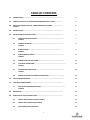
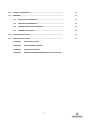
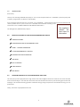
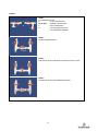
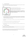
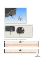
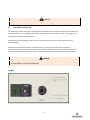
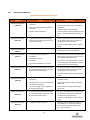
MADE IN CANADA MODELS S30‐S50 S60‐75‐95‐116 N75‐95‐116 H95 INSTALLATION & INSTRUCTION MANUAL SWIMMING POOL HEAT PUMP UNIT WARNING Read and comply with all safety information. Make sure you understand all instructions before using this product. WARNING DANGER In this manual, these warnings mean there is a safety message to comply with or that improper use could result in damage to the unit. When you see one, read it carefully. IMPORTANT! In this manual, this indication refers to the guarantee and procedures of service calls or referred to a recommendation. 2 TABLE OF CONTENTS INTRODUCTION…………………………………………………………………………………………………….. 5 PRINCIPAL FEATURES OF YOUR NIRVANA SWIMMING POOL HEATER…..…………….. 5 OPERATING PRINCIPLES OF THE THERMODYNAMIC HEAT PUMP…….……………………. FIGURE 1 ENERGY SAVING……..………………………………………………………………………………………….. 6 INSTALLATION OF YOUR HEAT PUMP……….…………………………………………………………… 7 5.1 CHOICE OF INSTALLATION SITE..………………………………………………………………… FIGURE 2 7 5.2 CONNECTING WATER……….………..……………………………………………………………… FIGURE 3 8 5.3 BYPASS SYSTEM…….…………………………………………………………………….......... FIGURE 4 9 5.4 WATER PRESSURE GAUGE…………..…………………………………………………………….. FIGURE 5 11 5.5 OPERATING OF THE HEAT PUMP……….………………………………………………………. 11 5.6 ELECTRICAL CONNECTION…………………..…………………………………………….…………… FIGURE 6 11 5.7 ECO ENERGETIC CONTACTOR……...…………………………………………………………….. FIGURE 7 13 5.8 OPERATING OF THE ECO ENERGETIC CONTACTOR……..………………………………. 14 1.0 2.0 3.0 4.0 5.0 6.0 7.0 8.0 9.0 HEAT PUMP MAINTENANCE …………….………………………………………………………………….. POOL WATER MAINTENANCE ………………………………………………………………………………. 7.1 POOL WATER MAINTENANCE CHART…………….….……….………..………………………. FIGURE 8 WINTERIZING …………………………………………..……………………………………………………….…. OPERATION OF THE ELECTRONIC CARD……………………………………………………………….. 9.1 FRONT PANEL DESCRIPTION (S & N‐SERIES) 9.2 FRONT PANEL DESCRIPTION (H‐SERIES) 9.3 SELECTION OF MODE (H95 ONLY) 3 6 15 15 15 16 17 17 18 19 10.0 11.0 12.0 13.0 TECHNICAL INFORMATION………………………………………………..…………………………………. 20 WARRANTY……………………………………………………………………….……………………...…………. 21 11.1 REGISTRATION OF WARRANTY…………………………………………………………………. 21 11.2 CONSUMER’S RESPONSABILITY………………………………………………………………… 21 11.3 11.4 MANUFACTURER’S LIMITED WARRANTY………………………………………………….. 22 WARRANTY EXCLUSIONS………………………………………………………………….......... 23 TROUBLESHOOTING GUIDE…………………………………………………………………………………. 24 CONTACTING THE FACTORY………………………………………………………………………………… 27 APPENDIX 1 OVERVIEW OF THE UNIT APPENDIX 2 HEAT EXCHANGER OVERVIEW APPENDIX 3 ELECTRIC BOX OVERVIEW APPENDIX 4 ADDITIONAL INFORMATIONS ABOUT THE HEAT GAS SYSTEM 4 1.0 INTRODUCTION Dear Owner, Thank you for choosing NIRVANA heat pump inc .You are now the proud owner of a « NIRVANA » pool heat pump that is industry‐recognized for its efficiency and reliability. Very economical and extremely easy to operate, your « NIRVANA » heat pump will ensure your full satisfaction and remain problem free for years to come if it is installed and maintained according to the instructions in the « OWNER’S MANUAL AND INSTALLATION GUIDE ». This appliance The Management, NIRVANA heat pump Inc. delivers the best value on the market. 2.0 PRINCIPALS FEATURES OF YOUR NIRVANA SWIMMING POOL HEATER 9 FIBERGLASS CABINET 9 SUPERIOR COEFFICIENT OF PERFORMANCE (COP) 9 SCROLL – DANFOSS COMPRESSOR 9 R‐410A ENVIRONNEMENTLY FRIENDLY 9 OVERSIZED BLUE FINE EVAPORATOR 9 VERY QUIET 9 EASY TO OPERATE 9 CARRY HANDLES 9 NEW DESIGN 3.0 OPERATING PRINCIPLES OF THE THERMODYNAMIC HEAT PUMP This heat pump comes equipped with a large surface heat collector (A) that allows the maximum heat to be extracted from the surrounding air. The heat thus recovered is then transferred to the water in your swimming pool via the heat exchanger. This method of heating generates substantial energy savings compared to conventional electric, gas or oil pool heaters. Finally, the cold air is (B) expelled of the unit. 5 FIGURE 1 IMPORTANT! SOLAR BLANKET In order to increase energy savings, we strongly recommend use of a solar blanket when the air is cooler, especially at night and at the beginning and end of the season. This will minimize heat loss and help reduce your heating costs. 4.0 ENERGY SAVING Did you know that at least 43% of heated pool owners choose heat pumps as pool heaters? And with good cause! This system has the highest output, is the most economical to operate and is the advantageous for maintaining the water in your pool at a constant temperature, day and night. Using a pool heat pump continuously to keep the pool’s water temperature at a constant 27 degrees Celsius (80 degrees Fahrenheit) from May to September inclusively costs only one fifth of what it costs to use a natural gas or propane pool heater. It also offers other advantages such as no longer worrying about energy supply, not being inconvenienced by combustion odors and protecting the environment from an ecological point of view. 6 5.0 INSTALLATION OF YOUR HEAT PUMP 5.1 CHOICE OF INSTALLATION SITE The installation site is a very important element in getting the most out of your pool heat pump. As described earlier, the heat pump captures energy from the air and transfers it to the pool water. When choosing the installation site, it is very important make sure there is enough room around the heat pump that is free of obstacles (wall, trees, hedges etc). The choice of site should allow easy access to the temperature control panel. FIGURE 2 A level surface is required to ensure the stability of the heat pump. We recommend using a concrete slab or patio stone. In addition to durability, these will not be affected by water condensation,* which may drip from the heat pump evaporator during operation. (1) Water condensation is the result of hot, humid air coming into contact with the cold surface of your heat pump's heat collecting coil. 7 WARNING NIRVANA heat pumps must never be installed in an enclosed area such as a garage or shed. 5.2 CONNECTING WATER 1. Connect the water line from the swimming pool filter to the «WATER IN» connector located at the base of the heat pump. 2. Connect the water line returning to the swimming pool to the «WATER OUT» connector located at the base of the heat pump. 3. Once all connections are made, turn the filter pump on to check water circulation and ensure that all connections are watertight. The flow rate must be at least 208 litters/minute (55 U.S. GPM / 46 imperial GPM). A circulation pump that reaches top performance with a flow of 208 litters/minute (55 U.S. GPM / 46 imperial GPM) must be installed to ensure you achieve sufficient water flow (minimum of 1.5 HP circulation pump is recommended). FIGURE 3 Connecting your heat pump to your pool’s water line is a simple operation that can be done by you or a qualified technician. All you will need is flexible pipe, 1½” in diameter inside, and stainless steel clamps. It is also possible to use rigid PVC pipe but this method is generally more difficult and expensive. 8 CAUTION The titanium heat exchanger has a single wall. This is not suitable for potable water. CAUTION The heat pump must be installed between the pool filter outlet and the swimming pool, as close as possible to the filter pump and the electrical hook‐up circuit to minimize connection costs and increase performance. Note that use of 90° elbows and short elbows should be kept to a minimum (FIGURE). CAUTION CHEMICAL PRODUCTS DISTRIBUTOR (CHLORINATOR) (FIGURE ) The titanium condenser has the great advantage of offering almost total protection against the water’s acidity or chemical products in the water. Furthermore, in order to decrease the risks of corrosion, if a chemical product dispenser (for chlorine or bromine) is included with the filtration system, an insulated check valve must be installed downstream in addition to the check valve in the automatic dispenser. ATTENTION NEVER INSTALL THE HEAT PUMP UPSTREAM FROM THE FILTER 5.3 BYPASS SYSTEM The use of a bypass valve system is not necessary for your heat pump to operate properly. Your heat pump is equipped with a “Full Flow” type heat exchanger that provides optimum performance with a water flow of 208 litters/minute (55 U.S. GPM / 46 imperial GPM). The heat exchanger was specifically designed to reduce to erosion to less than 2%. Erosion is caused by water flowing at high speed and the sanding effect produced by particles suspended in the water (sand, chlorine, etc). To facilitate maintenance and winterizing, however, we strongly recommend installing a bypass and/or service valve system. The design of the heat exchanger makes it easy to drain off the water inside. When the water pipes are disconnected in preparation for winterizing, because the pool water intake is directly at the base of the cylinder, the cylinder empties completely by itself, thus eliminating the risk of bursting due to freezing during cold weather. 9 FIGURE 4 TABLE 1 ILLUSTRATION OF PARTS A OUTLET WATER VALVE B1, B2 & B3 ASSEMBLY VALVE BYPASS C INLET WATER VALVE D PART NOT REQUIRED, ONLY FOR TEMPORARY ASSEMBLY TABLE 2 BYPASS SYSTEM ASSEMBLY TABLE 3 POSITION OF VALVES FOR CIRCULATION INTO THE HEAT PUMP TABLE 4 POSITION OF VALVES FOR DIVERSION OF WATER 10 5.4 WATER PRESSURE GAUGE The pipes connecting the different water filtration and heating components often include a large number of bypass and/or service valves, sometimes leading to inadequate or no water pressure. FIGURE 5 The pressure gauge should read between 5 and 15 Psi. A high water pressure reading on the filter gauge does not necessarily mean that enough water pressure is reaching the heat pump. A good pressure should be held in the green section. If the pressure is in the yellow section, you have to do a backwash. If the pressure is in red section, you have a problem with the out water of the machine. It might be a bad position of the bypass valve. OPERATION OF THE HEAT PUMP 5.5 1. The swimming pool water pump must always be ON when the heat pump is in operation. If the swimming pool water pump is equipped with a timer, make sure that the heat pump’s operating time is synchronized with the water pump’s operating time, with priority to the pool heater. The pool heater may have to operate for longer periods than the water pump of the swimming pool. 2. The heat pump may occasionally generate condensation in the form of mist when the relative humidity is at higher levels. 3. The condensation formed on the heat collector may cause dripping under the heat pump. 4. The use of a bypass valve system is always recommended to facilitate maintenance. 5. When starting the heat pump, the fan will start immediately but the compressor will take between 3 and 5 minutes to start up. ELECTRICAL CONNECTION 5.6 The NIRVANA heat pump has been designed to enable simple, easy and safe installation. There is no need to open the heat pump and risk making a mistake in the electrical hook‐up. All our models come with a junction box located at the base of the unit allowing quicker, simpler heat pump hook‐up. Note: You will find the heat pump’s electric plan at the end of this manual and on the inside of the electrical casing of your unit. This one must be connected to a food of 240v single‐phase current. 11 FIGURE 6 A B Do the connection in the respect of the National, provincial and local codes. CAUTION To guarantee your safety and ensure proper operation of your unit, the electrical hook‐up should be done by your POOL EXPERT or a CERTIFIED ELECTRICIAN according to national, state or provincial and municipal codes. A circuit breaker of sufficient rating and copper wire must be used and it may be necessary to install a ground. (FIGURE 6) CAUTION The power cable ground wire must be connected to the electrical panel and to the ground terminal boards in the heat pump’s junction box. Improper installation increases the risk of fire, and electrocution or injury. 12 WARNING Units installed within 5 feet of the pool walls must be protected by a ground fault circuit breaker. ECO ENERGETIC CONTACTOR The eco energy contactor is an option of our electronic chart which makes it possible your Nirvana unit to effectively manage the use of your circulating pump. The latter does not need to function 24 hours a day. Thus energy saving interesting for a better energetic efficiency. This option will always privilege the attack of your required temperature versus the time of operation of the circulating pump. Generally, the professionals of industry intend themselves to say that the circulating pump can function approximately 12 hours per day without to affect water quality according to of course the conditions weather or of the system of treatment of water which you use. Consult your swimming pool professional of the on this subject. 5.7 WARNING To guarantee your safety and ensure proper operation of this option, the electrical hook‐up should be done by your POOL EXPERT or a CERTIFIED ELECTRICIAN. FIGURE 7 13 5.8 OPERATING OF THE ECO ENERGETIC CONTACTOR Depending on heat pump instruction (heating required) (If connected to the electrical box and the contactor) NOTE: The magnetic contactor is used to intelligently control pool pump while providing better energy efficiency of your heat pump. (FIGURE 7) The HP727S features an adjustable minimum filtration period (FIL). A daily 24‐hour cycle is divided into 6 periods of 4 hours (240 minutes). The adjustable setting values represent the minimum total daily hours that filtration is required. FIL PARAMETER SETTINGS (If connected to electrical box) 2 hours to OFF ON 23 hours Pump operates between 2 and Pump is always OFF Pump is always ON. 23 hours a day. 1. In OFF mode, the circulating pump needs to be always on or programmed by an external timer. 2. In ON mode, the circulating pump is always on. The minimum filtration time selector is divided into 6 equal periods per day. E.g. Selection of 4 hours ÷ 6 periods = 40 minutes per period. The circulating pump will therefore operate 40 minutes of each period of 4 hours. The minimum filtration time that can be selected is 2 hours (6 periods of 20 minutes each). When the circulating pump is ON, if there is a need for heating during a filtration period: 1. The circulating pump will stay ON until heating is no longer needed. 2. During that period, the minimum filtration time counter meter is always on. 3. If the minimum daily filtration time is reached and heat is still needed, the circulation pump will stay ON until heat is no longer needed. If the minimum daily filtration time is reached and heat is not needed, there will still be 15 minutes of circulating time per period (every 4 hours). This is to sample the pool water temperature in case the water needs to be heated (not valid if FIL parameter is set to OFF). Whenever the FIL parameter is changed, the daily counter will reset. 14 6.0 HEAT PUMP MAINTENANCE WARNING SAFETY TIPS A) A certified electrician should perform all electrical connections (see the high voltage connection diagram). Always disconnect the heat pump before: • Opening the access panel • Cleaning the swimming pool filter • Cleaning the cabinet • Cleaning the evaporator C) Never sit or place heavy objects on the heat pump. D) Never put objects in or on the protective grille in order to avoid any risk of injury or breakage B) A) Inspect and clean the pool filter regularly to ensure adequate water flow to the heat pump. B) Inspect the evaporator and clean it by rinsing carefully, using a garden hose to direct a jet of water from the top to the bottom to prevent grass, leaves or other objects from blocking the evaporator. C) Clean the heat pump cabinet with mild soap (dishwashing soap). Do not use abrasive products or products containing bleach. D) Make sure that the skimmer is not blocked. 7.0 POOL WATER MAINTENANCE POOL WATER MAINTENANCE CHART 7.1 FIGURE 8 15 WARNING We recommend maintaining the pH level of the swimming pool at between 7.2 and 7.8. A higher pH level could damage the heat pump and other equipment and also void the warranty. Also, check the chlorine and the hardness of the water. (FIGURE 8) Before backwashing, stop the unit by putting the thermostat to the lowest temperature during the cleaning cycle. Never use the skimmer to add chemicals to your pool water. These recommendations are important to prolong the life of your heat pump and especially to protect your health. 8.0 WINTERIZING 1. Set the circuit breaker to the OFF position. 2. Drain the heat pump before the first frost. Unscrew all water connections. WARNING It is very important that all water connections to the pool are disconnected (bypass valve or other) to allow complete drainage of the heat pump. 3. Rinse the inside of the heat exchanger cylinder with a stream of city water for about 15 minutes to make sure chlorine does not remain on the exchanger and cause premature wear to the heat pump. Block the water intake or outlet and tilt the heat pump to the rear to remove any excess water 4. Block the water intake and outlet with rags or plastic to prevent access by small rodents or other animals. It is always a good idea to cover the heat pump with the NIRVANA tarpaulin for additional protection, see with your dealer for more information. NOTE: When you tilt the heat pump, do not tilt more than 30‐35° and always carry it vertically. RESTARTING 1) Visually inspect the heat pump. 2) Clean the swimming pool filter. 3) Balance the PH Level of the pool water. 4) Reconnect all water intake and outflow connections. 5) Set the circuit breaker back to the ON position. 16 9.0 9.1 1 2 3 4 5 6 7 OPERATION OF THE ELECTRONIC CARD FRONT PANEL DESCRIPTION (S & N‐ SERIES) Displays the current temperature of water. According to the programming, it can post other parameters Button `SET’ which is used to move in the various menus Button ‘INCREASE’ which is used to increase the temperature of water Button `DECREASE' which is used to decrease the temperature of water The green light means that we are in heating mode of the swimming pool The red light means that the Nirvana unit is in operation The green light means that we are in heating mode of the spa 17 9.2 1 2 3 4 5 6 7 FRONT PANEL DESCRIPTION (H‐SERIES) Displays the current temperature of the water. Button 'SET' which is used to move through menus Button ‘INCREASE’ which is used to increase the temperature of water Button `DECREASE' which is used to decrease the temperature of water The yellow light means we are in the POOL mode Means we are in HEATING mode Means the compressor is running WARNING The pump will go on and then the current water temperature will be displayed. The current temperature displayed is kept in memory and displayed for 5 minutes until the water temperature sensor has sampled the circulating water. After 5 minutes, the water temperature is automatically updated and displayed. ADJUSTING DESIRED TEMPERATURE (B,C &E‐SERIES) Settings: Pool OFF, 61° F à 95° F SPA option OFF, 61° F à 104° F OFF, 16° C à 35° C OFF, 16° C à 40°C The control is shipped set to OFF in POOL and SPA mode. (option) The heat pump stops automatically if a setting below 61° F / 16°C is selected. In OFF mode, the control will display the water temperature. Use the SET key to select POOL or SPA mode. Use the ↑ key to increase the desired setting to above 61° F / 16°C. The heat pump compressor operates automatically if a setting above 61° F / 16° C is selected. Adjust the settings to the desired value. 18 9.3 SELECTION OF MODE (MODEL H95 ONLY) To keep the unit in the HEAT MODE ONLY: Press the "SELECT" until "ACH" appears and press the arrow keys until "HEA" appears. Thereafter it remains only to choose the desired temperature. This feature allows you to control the minimum level desired. The unit will heat the water until the desired temperature is reached. To keep the unit in COOLING MODE ONLY: Press the "SELECT" until "ACH" appears and press the arrow keys until "COL" appears. Thereafter it remains only to choose the desired temperature. This feature allows you to control the desired maximum degree. The unit will cool the water until the desired temperature is reached. To put the unit in AUTO MODE: Press the button "SELECT" until "ACH" appears and press the arrow keys until "AU" appears. Thereafter it remains only to choose the desired temperature. This function keeps water at desired temperature. In other words, it will heat or cool water until the water temperature reaches the degree selected. BACKWASH OPERATIONS 1. Carry out the backwash procedure as follows: 2. Turn OFF the power to the pump (with power supply or (FIL = OFF, POL = OFF and SPA OFF)). 3. Prepare the system for backwash and power ON the pump (with power supply or (FIL = ON)). 4. The circulating pump will go ON and the controller will not check for 5 minutes if water flow is present at the flow switch. 5. You will have 5 minutes of uninterrupted water flow to do the backwash. 6. Stop the circulating pump (use the power supply or FIL=OFF). Normally, when the circulating pump is required for this operation and there is no water flow detected at the control, the pump will automatically turn OFF. This procedure will give a 5 minute period of uninterrupted water flow before the circulating pump turns OFF. CHANGING THE DISPLAY FROM F° TO C° Factory defaults are in F°. Press and hold down the SET key until the message POL appears. Press the SET key until F_C is displayed. Press the ↑ key to select °F or press the ↓ key to select °C. RESETTING THE DISPLAY If a flashing PLE or CSE error message is displayed, hold down the SET key until the error message is no longer displayed (approx. 4 seconds). The control will be reset to the factory default. Reprogram all the settings. DE‐ICING OPERATION During the evaporator coil de‐icing cycle, FS will be displayed to indicate that the unit is de‐icing. During this time, the fan is on and the compressor is not in operation. 19 10.0 TECHNICAL INFORMATION MODEL / FEATURES S30 S50 S60 S75 S95 S116 N75 N95 N116 H95 10 KW 14 KW 16 KW 21 KW 28 KW 34 KW 20 KW 26 KW 32 KW 27 KW 5,7 5,4 6,2 6,1 6,1 6 5,8 5,7 5,9 5,8 MAXIMUM BREAKER 20 30 30 40 50 50 10 15 15 50 POWER SUPPLY 240v 1ph 240v 1ph 240v 1ph 240v 1ph 240v 1ph 240v 1ph 380v 3ph 380v 3ph 380v 3ph 240v 1ph FREQUENCY 50 Hz 50 Hz 50 Hz 50 Hz 50 Hz 50 Hz 50 Hz 50 Hz 50 Hz 50 Hz COMPOSITE COMPOSITE COMPOSITE COMPOSITE COMPOSITE HEATING CAPACITY PERFORMANCE (COP) CABINET COPOLYMÈRE COPOLYMÈRE COMPOSITE COMPOSITE COMPOSITE COMPRESSOR SCROLL SCROLL SCROLL SCROLL SCROLL SCROLL SCROLL SCROLL SCROLL SCROLL REFRIGERANT R‐410 A R‐410 A R‐410 A R‐410 A R‐410 A R‐410 A R‐410 A R‐410 A R‐410 A R‐410 A 20 DE‐ICING OPERATION During the evaporator coil de‐icing cycle, FS will be displayed to indicate that the unit is de‐icing. During this time, the fan is on and the compressor is not in operation 11.0 WARRANTY 11.1 REGISTRATION OF WARRANTY Although NIRVANA HEAT PUMP INC. heat pumps of are of high quality and are subject to all appropriate controls during manufacturing, it is important to fill out the registration card WITHIN TEN DAYS OF PURCHASE to provide us with your contact information (name and addresses) so that we are able to contact you in the event of a product recall. Without your co‐operation in completing the registration card, NIRVANA heat pump Inc. will be unable to advise you of this situation. 11.2 CONSUMER’S RESPONSABILITY REGISTRATION CARD The warranty registration card included with the Owner’s Manual must be returned to NIRVANA heat pump Inc. within 10 days of purchase. The customer is responsible for the cost of all calls for service made to obtain instructions on how to operate the system or to correct improper installation of the system that is not approved by NIRVANA heat pump inc. and not in compliance with the instructions given in manual. This warranty does not cover the cost of preventive maintenance. We suggest you contact an authorized NIRVANA heat pump Inc. dealer for an annual inspection and preventive maintenance of your system. MODEL AND SERIAL NUMBERS The model and serial numbers of the NIRVANA unit covered by this warranty must be clearly written on the registration card. Verify that the numbers on the heat pump’s data sheet match the numbers on the registration card. You are responsible for informing NIRVANA heat pump Inc. if the identification numbers do not match. PURCHASE INVOICE You must keep your original purchase invoice showing the date the heat pump was purchased, the installation date, and the model and serial numbers so that this information is always available for written or verbal communication with the technician, dealer or manufacturer. IMPORTANT – SERVICE CALL To make a call for service under the terms of this warranty, you must communicate with your dealer and make sure you can provide the model of the appliance, the serial number, present the original invoice indicating the dates of purchase and installation of the heat pump and a detailed description of the problem 21 IMPORTANT READ THE ATTACHED LIMITED WARRANTY CERTIFICATE 11.3 MANUFACTURER’S LIMITED WARRANTY NIRVANA HEAT PUMP offers a limited warranty against defects in the operation of the heat pump. This warranty becomes effective from the date of installation (with a proof of installation provided by the dealer) and is valid only for new heat pumps. (residential sector only) The heat pump must be installed according to manufacturer specifications and must be operated under the conditions of normal use recommended by the manufacturer. During the life of the warranty NIRVANA HEAT PUMP INC. agrees to repair or replace at its own discretion any parts deemed defective by the technician or authorized representative of NIRVANA HEAT PUMP INC, insofar as they have been used under appropriate conditions; any and all replacement parts must be original parts or approved by NIRVANA HEAT PUMP INC. for all swimming pool heat pumps manufactured by NIRVANA HEAT PUMP INC. IMPORTANT The use of unauthorized parts voids this warranty. The warranty is valid only as long as the pool heat pump is installed at the original address of the original purchaser. Excepting written agreement to the contrary, all repairs or replacements of defective parts by a qualified technician are guaranteed for the period not exceeding the initial term of this agreement. Heat pumps are much more sophisticated than simple household appliances and servicing by a “handyman” is not recommended. Have any servicing carried out by a recognized refrigeration technician. IMPORTANT Evidence of servicing or repairs carried out by a person other than a technician authorized by NIRVANA will result in the cancellation of this warranty. The manufacturer will not be liable for accessory or indirect damage resulting from improper installation and from the use of or the inability to use the appliance. The manufacturer offers no other warranty of any nature whatsoever. No distributor or dealer is authorized to modify the terms and conditions of this warranty. Coverage under any additional warranty provided by a distributor or dealer is the sole responsibility of that distributor or dealer. The Service Warranty continues in effect insofar as the product remains at the owner’s original address and was installed according to the standards and recommendations in the Owner’s Manual, or until the expiry of this warranty. This warranty applies to the original purchaser and is transferable to successors only if the heat pump remains at the original installation site 22 WARNING This agreement may be transferred to a second owner at the same address by sending a written request to NIRVANA heat pump Inc. accompanied by a check or money order in the amount of 100.00$ (+ Canadian taxes) to cover transfer and administrative fees. WARNING REPLACEMENT OR REPAIR PURSUANT TO THE LIMITED WARRANTY CONSTITUTES THE SOLE REMEDY. 11.4 WARRANTY EXCLUSIONS IMPORTANT THIS LIMITED WARRANTY DOES NOT COVER DAMAGE OR IMPROPER OPERATION CAUSED BY : a) Improper use or maintenance of the heat pump that does not comply with the instructions in the Owner’s Manual, provincial or state building codes or municipal regulations. b) Improper installation of the heat pump or installation performed by persons not authorized by the Company. c) Improper use, negligence, accident or force majeure which includes such events as flood, lightning, earthquake, tornado, hail and any other unpredictable, irresistible event known as an “Act of God.” d) Freezing or erosion of the piping or the internal components of the heat pump due to improper winterizing, poor water quality, infiltration of sand or other abrasive substances into the heat pump’s internal workings. e) Premature corrosion of the titanium coolant tubing resulting from improper use of chemical products in the pool (e.g.: pH, chlorine or salinity levels that are above or below the standard). Modification, alteration, repair or replacement of parts performed by persons not authorized by the company. 23 12.0 TROUBLESHOOTING GUIDE MAINTENANCE & TROUBLESHOOTING CODE PROBLEM Digital control displays CODE: FLO Digital control displays CODE: FL3 Digital control displays CAUSE WHAT TO DO The water flow inside the heat pump is insufficient There is no water circulation inside the heat pump CODE: LP The heat pump flow switch has cut off three (3) times in the same hour for one of the reasons above The heat pump will not re‐start after one of the protection devices shuts it down for the third time in the same hour; Close the circuit breaker to reset the heat pump. The heat pump is in de‐icing mode Wait until the end of the de‐icing cycle. The heat pump will restart automatically Ventilation on the evaporator is insufficient. Check that the evaporator is not blocked by pollen, grass, leaves; see the user’s manual for safety and maintenance tips The fan does not work The outside temperature is very low CODE: LP3 Check the skimmer (no blockage); Check the water pressure gauge of the heat pump, it should read between 10 and 15 psi. Freon leak Digital control displays Check that the bypass valves are properly positioned; The flow switch is defective CODE FS Digital control displays Check that the circulating pump is working; The heat pump low pressure switch has cut off three (3) times in the same hour for one of the reasons above Be sure there is enough free space around the heat pump (see the Installation Guide) Check that the fan is powered ON The heat pump will not re‐start after one of the protection devices shuts it down for the third time in the same hour Close the circuit breaker to reset the heat pump Digital control displays CODE: HP Digital control displays CODE: HP3 The water flow inside the heat pump is insufficient Check whether there is adequate water circulation inside The bypass valve is in the wrong position The water exit is blocked. Check that the bypass valves are properly positioned There is a blockage in the refrigeration circuit (piping blocked) Check whether anything is blocking the water hose The heat pump high pressure switch has cut off three (3) times in the same hour for one of the reasons above The heat pump will not re‐start after one of the protection devices shuts it down for the third time in the same hour Close the circuit breaker to reset the heat pump Digital control displays The digital control is defective CODE SPI 24 Close the breaker switch and re‐open it. If the problem is not resolved, the digital control will have to be changed. In this case, call your dealer Digital control displays CODE DPO Digital control displays CODE PO Digital control displays The de‐icing sensor is not properly connected or is not receiving power Call your dealer The water temperature sensor is not properly connected or is not receiving power Call your dealer The de‐icing sensor is defective Call your dealer The water temperature sensor is defective Call your dealer CODE DPC Digital control displays CODE PC Heat is needed, the fan is Electrical problem in the compressor circuit functioning, no code is displayed and the Capacitor defective compressor does not Compressor defective start Call your dealer QUESTIONS‐ANSWERS HEAT PUMP FAILS TO OPERATE... Is the display illuminated? Is the green light illuminated? If not, ensure the breaker is turned ON. The red light illuminates when the unit runs only (fan, compressor, etc.) HEAT PUMP RUNNING...BUT IS IT HEATING? Is the air blowing out of the top of the unit noticeably cooler than the surrounding air? (A 9°F to 12°F difference is typical.) Be sure all air coil surfaces are free from obstructions (roof overhangs, landscaping, walls, fences, etc., can restrict air flow). The heat pump needs good airflow to operate at peak efficiency. How many hours/day does the circulating pump operate? Cooler weather conditions, or heating to a higher than normal, may necessitate running the heat pump for a longer period of time. Was the heater sized considering the use of pool blanket? A blanket can be useful in permitting shorter run times, in turn leading to substantial energy cost savings. What it the air outside temperature? The heat pump may be in the defrost mode if air temperature are below 50°F or if the water temperature is around 77°F. If the heater is in defrost, the code “FS” will be displayed. If air temperature are not cold, but the heater remains in defrost, contact your retailer. WATER COMING FROM THE HEAT PUMP... Is it a leak or just condensation from normal operation? Here's how to find out. Shut the heat pump off, leaving the circulation pump running. Within a few hours, there should be a marked reduction in the amount of water seen around the bottom of the heat pump. If the water appears to be drying up, the water is probably harmless condensate, indicative of normal operation. 25 TECHNICAL ASSISTANCE SERVICE SERVICE CALL NIRVANA heat pump Inc. will authorize service only on heat pumps that are under warranty. Costs incurred by a refrigeration technician for a service call that was not authorized beforehand must be borne by the CUSTOMER. CAUTION BEFORE PLACING A CALL FOR SERVICE To avoid situations where a service call or repair is not covered by the warranty as described in the owner’s manual, we advise you to check that: At all times: There is always a possibility of condensation, especially if conditions are humid. (Condensation is the result of hot, humid air coming into contact with the cold surface of your heat pump’s coil). Condensation should not be confused with leaking. a) The breaker or the fuse is ON and the heat pump is properly connected (green indicator light on the unit). b) The circulating pump is running at full capacity, is the right size (1.5 HP is recommended) and the filters are clean. c) The gauge on the heat pump indicates between 10 and 15 psi, for sufficient flow (carry out a backwash). d) Service valves (water intake and water outlet) are in the open position and the bypass valve is closed. e) The thermostat is set high enough. f) The design of the plumbing is in keeping with best practices. g) The fins are not blocked by pollen, leaves, grass, etc. (clean with a garden hose, from top to bottom and not towards the inside of the machine). h) When the air temperature varies by about 7°C, the heat pump may then enter a cycle of stops and starts as it goes into de‐icing mode. During cold weather, frost may form on the evaporator. This is normal. However, if you see ½” of ice or more, contact us immediately. REPAIR If your heat pump still does not operate after these verifications, contact your seller or your manufacturer. 26 All replacements must be made with original parts in order to maintain your heat pump’s proper performance, durability and safety, and continue your warranty. It is prohibited to modify or remove a safety device. The manufacturer disclaims all responsibility if installation instructions are not followed or if electrical or mechanical components and/or safety devices have been modified in any way. Notify us immediately of any warranty difficulties with the authorized vendor in your area. 13.0 CONTACTING THE FACTORY If you should need to call us for service or parts, please have the following information ready that will speed the service process and allow us to respond more quickly: Model: Serial Number: Retailer: Installation Date: Please call us toll‐free at: 1(866) 443‐4476. We are here to serve you from 8 a.m. To 4: 30 p.m. EST, Monday through Friday. If calling after hours leave a short message. Be sure to leave your name and daytime telephone number. If you prefer, you may fax the information to: (819) 539‐4431. Be certain to provide your full address and daytime telephone number. Thank you! NIRVANA CHAUFFE‐PISCINE INC. 4162, RUE BURRILL SHAWINIGAN (QUÉBEC) CANADA G9N 6T6 TÉL/PHONE: (819) 539‐8698 TÉLEC/FAX: (819) 539‐4431 SANS FRAIS/TOLL FREE : 1 (866) 443‐4476 WWW.NIRVANAHP.COM [email protected] INSTALLATION – INSTRUCTION MANUEL UPDATE 2010‐01 27