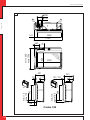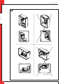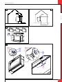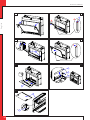
1
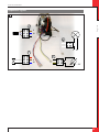
English Centro 100 G20/G25.3 Natural gas Store this document in a safe place 959.052.00UK DRU132368-394793-EN--0913-1 Installation manual (UK/IE) UK INSTAL L ATIO N MA N U A L Contents English 1. Introduction 2. CE declaration 3. SAFETY 3.1 General 3.2 Regulations 3.3 Precautions / safety instructions at installation 3.4 Principle of ignition cycle 4. Removing the packaging 5. Installation 5.1 Type of gas 5.2 Gas connection 5.3 Electric connection 5.4 Placing the appliance 5.5 Placing a built-in appliance 5.6 Placing the chimney breast 5.7 Placing the control hatch 5.8 Flue gas discharge system appliances open combustion 5.9 Flue gas discharge / combustion air supply system appliances closed combustion 5.10 Additional instructions 5.11 Construction frame 5.12 Glass panes 5.13 Setting the appliance 5.14 Placing the wood set and Grey Cokes set 6. Wireless remote control 7. Final inspection 7.1 Gastightness 7.2 Gas pressure/line-pressure 7.3 Ignition main burner 7.4 Flame picture 8. Maintenance 8.1 Parts 9. Delivery 10. Malfunctions Appendix 1 Malfunctions Appendix 2 Various tables Appendix 3 Figures UK INST AL L AT I ON M AN U A L 1. Introduction English DRU, a manufacturer of gas-fired heating appliances, develops and produces products that comply with the highest possible quality, performance and safety requirements. This appliance has a CE label, which means that it complies with the essential requirements of the European Gas Appliance Directive. The appliance is supplied with an installation manual and a user manual. As an installer, you must be certified and competent in the field of gas-fired heating and electricity. The installation manual will give you the information you need to install the appliance in such a way that it will operate properly and safely. This manual discusses the installation of the appliance and the regulations that apply to the installation. In addition, you will find technical data for the appliance and information on maintenance, any malfunctions that might occur and their possible causes. The figures can be found at the back of this booklet, in the appendix. Please, read and use this installation manual carefully and completely, prior to installing this appliance. If you use the DRU Powervent system®, the DRU Smartvent system® or the DRU Maxvent system®, you must carefully and fully read and use the accompanying installation manual as well, prior to its installation. Ø !Tip !Caution !Caution The following symbols are used in the manuals to indicate important information: Work to be performed Suggestions and recommendations You will need these instructions to prevent problems that might occur during installation and/or use. You need these instructions to prevent fire, personal injury or other serious damages. After delivery, you should give the manuals to the user. 2. CE declaration We hereby declare that the design and construction of DRU's gas-fired heating appliance comply with the essential requirements of the Gas Appliance Directive. Product: Type: EEC directives: Standards: gas-fired heating appliance Centro 100 2009/142/EC; 2006/95/EC; 2004/108/EC NEN-EN-613; NEN-EN-613/A1; EN60335-2-102 Internal precautions at the company will guarantee that appliances produced in series comply with the essential requirements of the EC directives in force and the standards derived from them. This declaration will lose its validity if adjustments are made to the appliance without prior written permission by DRU. You will be able to download a copy of the test certificate via www.druservice.com. M.J.M. Gelten General manager Postbus 1021, 6920 BA Duiven Ratio 8, 6921 RW Duiven www.dru.nl UK INSTAL L ATIO N MA N U A L 3. SAFETY 3.1 General !Caution - Please observe the general regulations and the precautions/safety instructions in this manual. First check the exact technical version of the appliance to be installed in Appendix 2, Table 2. 3.2 Regulations English Please install the appliance in accordance with the applicable national, local and constructional (installation) regulations. 3.3 Precautions / safety instructions at installation Ø Carefully observe the following precautions/safety regulations: You should only install and maintain the appliance if you are a certified and competent installer in the field of gas-fired heating and electricity; do not make any changes to the appliance; if you are installing an appliance that must be built in; use non combustible and heat-resistant materials for the chimney breast, including the top of the chimney breast, the material in the chimney breast and the back wall against which the appliance will be placed. For this you can use both sheet material and stone-like materials; take sufficient measures to prevent temperature of a wall behind the chimney breast becoming too high, including the materials and/or objects behind the wall; comply with the minimum required internal sizes of the chimney breast; vent the chimney breast by means of ventilation holes with a combined passage as stated further down in the text; use heat-resistant electrical wiring; place heat-resistant electrical wiring away from the appliance and as low as possible in the chimney breast. This has to do with the temperature development in the chimney breast. if you are installing an appliance type B11 with open combustion: please use a suitable flue gas discharge system that is provided with the CE label; if you are installing an appliance with closed combustion: only use the concentric systems supplied by DRU; if you are installing a free-standing appliance: place the appliance away from the back wall by the minimum distance stated further down in the text; do not cover the appliance and/or do not wrap it in an insulation blanket or any other material; make sure that combustible objects and/or materials have a distance from the appliance of at least 500 mm; only use the accompanying wood/pebble set and place it exactly as described; leave the area around the ionization pin and spark plug free; make sure there is no dirt in gas pipes and connections; place a gas tap in accordance with applicable regulations; prior to putting into operation, check the complete installation for gastightness; if your appliance is provided with explosion hatches on its top and/or bottom, you must make sure that they cannot be blocked and check whether they fit well onto the sealing surface, prior to building in the appliance; do not ignite the appliance before the gas, discharge and electric connections have been fully installed, first observe the procedure described in chapter 7.3; replace broken or torn glass panes. !Caution In case of broken or torn glass panes, the appliance may not be used. Ø Ø Ø Ø Ø Ø Ø Ø Ø Ø Ø Ø Ø Ø Ø UK INST AL L AT I ON M AN U A L 3.4 Principle of ignition cycle English Below you will find a brief description of how this appliance is ignited. The appliance is off and will be switched on by means of the remote control. The receiver will get the signal to start the ignition process. This signal is passed on to the burner device, after which, if applicable, the relay for the Powervent System® is switched. After an 8 second interval, the ignition on the spark electrodes will start. If no Powervent System® is connected, only the relay will switch and the ignition will start immediately. The main burner will be ignited at 50% of its capacity. This will prevent a larger amount of gas in the combustion chamber, if no ignition takes place. When the gas ignites, ionization will have to be detected. In order to make sure the flame has passed over, this will take place at the other side of the burner. When ionization is detected, the gas control will modulate to 100%. If applicable, the second valve is switched (you will be able to hear a 'click') in order to ignite the second burner. After ignition of the second burner, the appliance will always go to the full position (full capacity). This will guarantee that the second burner will actually ignite. The second burner can be switched on and off manually, by means of the remote control. In case of switching on manually, the appliance will first return to full load. 4. Removing the packaging Ø Ø Ø Ø Note the following items when removing the packaging: Check the appliance and accessories for damages (during transport). If necessary, contact your supplier. Never install if an appliance is damaged! Remove any screws that are used to fix the appliance to a platform or pallet. !Caution Glass is a ceramic material. Very small irregularities in the glass panes cannot be avoided, but are within the required quality standards. !Caution Keep plastic bags away from children. Ø Ø In Appendix 2, Table 1 you can see which parts you should have after removing the packaging. Contact your supplier if you do not have all the parts after you finished removing the packaging. Packaging must be disposed of in accordance with the regulations. UK INSTAL L ATIO N MA N U A L 5. Installation Read this manual carefully to ensure the proper and safe installation of the appliance. !Caution Install the appliance in the order described in this chapter. Ø Please install the appliance in accordance with the applicable national, local and constructional (installation) regulations. Observe the regulations/instruction in this manual. English Ø 5.1 Type of gas The data plate indicates for which type of gas, gas pressure and for which country this appliance is intended. The data plate can be found on the appliance or can be attached to a chain to which it should remain attached. !Caution Check whether the appliance is suitable for the type of gas and gas pressure used at the location. !Tip If you want to convert this appliance into a different type of gas, please contact DRU's service department and ask what is possible. 5.2 Gas connection Place a gas tap in the gas pipe in accordance with the applicable regulations. !Caution Make sure there is no dirt in gas pipes and connections; The following requirements apply to the gas connection: use a gas pipe with the correct dimensions, so that no pressure loss can occur; the gas tap must be approved (in the EU this will be the CE mark); you should always be able to reach the gas tap. 5.3 Electric connection !Caution In case of a 230 Volt electrical connection, provide proper grounding, if applicable. Place this electrical connection away from the appliance, as low as possible in the chmney breast. This has to do with the temperature development in the chimney breast. If possible, place the receiver after any building work has been completed. If this is not possible: Protect the receiver against dust and moisture created during the building process! 5.3.1 Connecting the switch contact (if applicable) It is possible to operate one or more lamps (in case of several lamps, a maximum of 8A/250VAC/30VDC) via the remote control of the appliance. You could think of the lamps of Dru's lux elements. For this, you can use switch contact B on the receiver (see appendix 3, fig 1). The switch contact is not polar sensitive. 5.3.2 Connecting the Dru Omivent (if applicable) If the appliance is equipped with a Dru Lux Omnivent system, it can be operated with the remote control and connected (see appendix 3, fig 1, (C)). The supply to this connection is equal to the mains voltage. 5.4 Placing the appliance !Caution - UK Always place the appliance with a minimum distance of 500 mm from combustible objects or materials; Place the discharge pipes in such a way that situations with risk of fire can never occur; Always place the appliance in front of a wall of non combustible and heat-resistant material; Always maintain a minimum distance between appliance and back wall, if indicated in the dimensional drawing (see Appendix 3, Fig. 3); Take sufficient measures to prevent temperature of a wall behind the chimney breast becoming too high, including the materials and/or objects behind the wall; Do not cover the appliance and/or do not wrap it in an insulation blanket or any other material; Make sure that the appliance to be installed has a stable position. If applicable, this could be done by fixing the extension legs with self-tapping screws. !Caution When installing an appliance that has to be built in, take the following into account; The minimum construction measurements according to Appendix 3, Fig. 2 and 3; The construction height of the appliance, which you can determine yourself. Ø Ø Provide a gas connection at the location. For details, see section 5.2. Make a passage for the flue gas discharge system or the concentric system with the following diameters; for details, see section 5.8 or 5.9: the pipe diameter +10 mm for a passage through non combustible material; the pipe diameter +100 mm for a passage through combustible material; !Caution Additional instructions, specifically for the appliance that you are installing, start at chapter 5.10. English INST AL L AT I ON M AN U A L 5.5 Placing a built-in appliance (if applicable) Not all built in appliances by DRU are supplied with a control hatch. If it is not included, this control hatch is available separately. We recommend using the Dru control hatch at all times. In this chapter, it is assumed that the appliance is used with a control hatch. !Caution If you do not use a recommended Dru control hatch, please strictly observe the safeguards and necessary instructions stated in chapters 5.5 to 5.7. If you are not using the control hatch, please take the following into account as well: the accessibility of components that are normally placed in the control hatch; the maximum temperature of these components (maximum 60 °C). The gas control is mounted to the appliance. It must be taken out and placed in the control hatch at a later time. For placing the gas control in the control hatch, see section 5.7. Ø Ø Proceed as follows: Remove the bracket with, amongst other things, the gas control from the appliance by unscrewing the self-tapping screws. Place the bracket to which, amongst other things, the gas control is mounted, together with the wiring of the ignition/ionization cable(s), the flexible gas hose(s) and the data plate with chain in the direction of the control hatch. !Caution - Make sure there is no dirt in gas pipes and connections; Avoid kinks in the pipes. !Caution - Make sure the ignition cables cannot come into contact with other wies; The data plate should remain connected to the chain. Ø Ø Set the height of the appliance using the adjustable feet and Make the appliance level at the same time. !Tip The construction frame for most 2 or 3 sided appliances can be adjusted. This will allow you to connect the construction frame to the chimney breast correctly. For 2 or 3 sided appliances that cannot be adjusted, we would like to refer you to chapter 5.10 'Additional instructions'. !Caution do not ignite the appliance before the gas, discharge and electric connections have been fully installed, first observe the procedure described in chapter 7.3. UK INSTAL L ATIO N MA N U A L 5.6 Placing the chimney breast (if applicable) In order to provide proper heat discharge, there should be sufficient space around the appliance. The chimney breast should be ventilated sufficiently by means of ventilation holes (incoming and outgoing). !Caution - English - !Caution - When installing an appliance with mantelpiece, specific dimensions may apply for the opening in the chimney breast. When an appliance is built in the floor, please take into account the minimum distances from a combustible floor. If this applies to your situation, you will find more information on this from chapter 5.10 'Additional instructions'. Use non combustible and heat-resistant materials for the chimney breast including the top of the chimney breast, the material in the chimney breast and the back wall of the chimney breast; Make sure the appliance is not carrying the weight of the chimney breast when using stone-like materials; The passage of the ventilation holes (outgoing), which are placed as high as possible, is stated in Appendix 2, Table 2. !Caution When placing the chimney breast, you should take the following into account (see Appendix 3, Fig. 3): The location for the control hatch: this must be placed as low as possible; The dimensions of the control hatch; see Placing the control hatch section 5.7; The Dru control hatch is not supplied with all appliances. Nevertheless, we recommend only using a Dru control hatch, which can be supplied separately, if necessary. If you decide not to take this option, you will have to make a 100 cm2 ventilation hole that is placed as low as possible, for the benefit of the incoming ventilation. The location of the ventilation holes (V) (outgoing); Maintain a minimum 30 cm distance between the top of the ventilation hole (outgoing) and the ceiling of the house; The measurements of the glass pane, so that it can be placed/removed after placing the chimney breast; The protection of the gas control and the pipes against cement and plaster. !Tip You should preferably apply the ventilation holes (outgoing) on both sides of the chimney breast. You can use DRU ventilation elements. Prior to completely closing the chimney breast, check: whether the discharge / concentric system is placed correctly; whether the channels, fixing brackets and possible clip bindings, which cannot be reached after installation, are fastened by means of self-tapping screws. Ø Ø If applicable, do not plaster on or over the edges of the construction frame, because: the heat of the appliance could cause cracks; it will no longer be possible to remove/place the glass pane. When using stone-like materials and/or plaster finishing, allow the chimney breast to dry for at least six weeks prior to taking the appliance into operation in order to prevent cracks. 5.7 Placing the control hatch (if applicable) The control hatch (also see paragraphs 5.5 and 5.6) is placed as low as possible in the chimney breast. !Caution - The bottom of the control hatch may not be placed higher in the appliance than the burner surface. Place control hatch and bracket with gas control and accessories indoors in a dry place only! A number of components are placed in the control hatch, such as data plate, gas control, receiver belonging to the remote control and, if applicable, the components belonging to the DRU Powervent System®. UK Ø Place the control hatch as follows, see Appendix 3, Fig. 4 for details: Make an opening in the chimney breast, as described in the manual for the control hatch. !Tip The opening in the chimney breast may be made horizontal and vertical. Ø Place the inner frame (A); unscrew bolts (D and F) for this. !Caution - The inner frame should be placed in the correct way. Two positions are possible. Placing the inner frame with a rotation of 180° is not allowed (see Appendix 3, fig. 5). !Tip - When the chimney breast is made of bricks, the inner frame can be built with bricks at the same time; When using a different material, you can glue the inner frame or fix it with four flush screws. Ø Ø Remove the bracket with the components (B) from the appliance. Mount the bracket with components to the inner frame (A). Proceed as follows: Unwind the cables. This will, amongst other things, prevent a poor operation of the ignition. Unwind the flexible gas pipe(s). Mount the bracket with components to the inner frame (A). The lock hole will fall into the allen screw (C); the hole at the bottom will fall over the head of the allen screw (D). Fix the bracket with allen screw (C). !Caution - Ø Ø Ø Make sure there is no dirt in gas pipes and connections. Connect the gas pipe with gas tap. Bleed the gas pipe. !Tip If the gas tap is closed, you can simply remove the bracket with components by loosening the compression fitting under the gas control and loosening the allen screw (C) a few strokes. The bracket with components can now be lifted and removed from the control hatch in a forward movement. Ø Ø Ø Connect the 230 V mains voltage with earth connection. Various types of plug connections are supplied. The type of plug depends on the country where the appliance is placed. Place the data plate in its intended clamp (G). Mount the outer frame with door (E) to the inner frame using two allen screws (D and F). !Tip You can place the outer frame in such a way, that the door turns to the left or to the right. !Caution Always close the control hatch with the lock (H) because of the electricity behind the door (230V). You can operate the lock with a fitting flat object. English INST AL L AT I ON M AN U A L Avoid kinks in the pipes. Do not lay the cables of the ionization pins and spark electrodes along metal parts. 5.8 Flue gas discharge system at appliances with an open combustion (type B11) For connection to an existing chimney without a discharge pipe or flexble SS discharge – only allowed in Great Britain – the instructions provided in the separately supplied booklet 'Fitting into a conventional class 1 chimney' apply. In addition to the installation instructions, this booklet also contains supplementary tests. 5.8.1 General The appliance's type of discharge system is stated in Appendix 2, Table 2. The appliance must be connected to an existing or newly to be built chimney, according to the applicable, national, local and constructional (installation) regulations. 5.8.2 Connection of flue gas discharge system (if a class 1 chimney is not applicable) At least a 3 metre discharge pipe or a flexible SS discharge should be connected to the appliance. Bends in the flue gas discharge system are not allowed. !Caution - !Caution Maintain a distance of at least 50 mm between the outside of the concentric system and the walls and/or ceiling. If the system is built in (for instance) a cove, it should be made with non combustible material all around it; Use heat-resistant insulation material when passing through combustible material; Use a flue gas discharge system with the correct diameter, and which is provided with the CE mark; Some heat-resistant insulation materials contain volatile components that will spread an unpleasant smell for a prolonged time; these are not suitable. UK INSTAL L ATIO N MA N U A L Place the flue gas discharge system as follows: Connect the pipe pieces or flexible SS discharge. You should only install the appliance in a well ventilated room which complies with the applicable national, local and constructional (installation) regulations, in order to guarantee sufficient air supply. !Caution - English Ø Ø In case of a house with a mechanic exhaust system and/or an open kitchen with cooker hood, a permanent ventilation hole is required in the area surrounding the appliance; for this application, please refer to the gas installation regulations and local legislation. 5.9 Flue gas discharge /combustion air supply system at appliances with a closed combustion 5.9.1 General The appliance's type of discharge system is stated in Appendix 2, Table 2. The appliance is connected to a combined flue gas discharge/combustion air supply system, hereafter referred to as the concentric system. The passage to the outside can be made with both a wall terminal and roof terminal. If necessary, you can also use an existing chimney (see section 5.9.4). !Caution - - Only use the concentric system supplied by DRU This system has been tested in combination with the appliance. DRU cannot guarantee a proper and safe operation of other systems and does not accept any responsibility or liability for this; For connecting to an existing chimney you should only use the chimney kit supplied by DRU. The concentric system is constructed from (the flue spigot of) the appliance. If, due to constructional circumstances, the concentric system is placed first, it is possible to connect the appliance by means of a telescopic pipe piece. 5.9.2 Construction of the concentric system Depending on the construction of the concentric system the appliance will have to be further adjusted with possibly a restrictor slide or air inlet guide. See Tables 4 and 6 for determining the correct adjustment and section 5.9, 'Adjustment of the appliance' for the method of working. The concentric system with wall or roof terminal has to comply with the following conditions: First, a concentric pipe of minimum length should be connected vertically to the appliance, according to Appendix 2, Table 4 or 5. Determine the permissibility of the required discharge. When using a wall terminal the following applies: The total vertical pipe length, when using a wall terminal, may have a maximum length that you can find in Appendix 2, Table 4. In that case, a 90º bend will be connected after the vertical part; The total horizontal pipe length, when using a wall terminal, may have a maximum length that you can find in Appendix 2, Table 4 (without wall terminal; see Appendix 3, Fig. 6). When using a roof terminal the following applies: The construction of the chosen system, when using a roof terminal, must be permissible according to Appendix 2, Table 5 (See the method of working described below). The working method below indicates how the permissibility is determined of a concentric system when using a roof terminal. 1) Count the number of 45° and 90° bends required; 2) Count the total number of whole metres of horizontal pipe length; 3) Count the total number of metres of vertical and/or sloping pipe length (roof terminal excluded); 4) In the first 2 columns of Table 5, look for the number of bends required and the total horizontal pipe length; 5) In the top row of Table 5, look for the required total vertical and/or sloping pipe length; 6) If you end up in a box with a letter, the concentric system chosen by you is permissible; 7) Use Table 6 to determine how the appliance should be adjusted. UK INST AL L AT I ON M AN U A L 5.9.3 Placing the concentric system - - Maintain a distance of at least 50 mm between the outside of the concentric system and the walls and/or the ceiling. If the system is built in (for instance) a cove, it should be made with non combustible, heat-resistant material all around it; Use heat-resistant insulation material when passing through combustible material; The rosette of the wall terminal is too small to seal the opening when passing through combustible material. That is why you should first apply a sufficiently large heat-resistant intermediate sheet to the wall. Then, the rosette is mounted on the intermediate sheet. English !Caution The roof terminal can end in a sloping and a flat roof. The roof terminal can be supplied with an adhesive plate for a flat roof or with a universally adjustable tile for a sloping roof. !Caution Ø Ø Ø Ø Ø Ø Ø Ø !Caution Some heat-resistant insulation materials contain volatile components that will spread an unpleasant smell for a prolonged time; these are not suitable. Place the concentric system as follows: Build the system up from (the flue spigot of) the appliance. Connect the concentric pipe pieces and, if necessary, the bend(s). On each connection, apply a clip binding with silicon sealing ring. Use a self-tapping screw to fix the clip binding to the pipe on locations that cannot be reached after installation. Apply sufficient wall brackets, so that the weight of the pipes does not rest on the appliance. Determine the remaining length for the wall or roof terminal and cut it to size, make sure the correct insertion length is maintained. Place the wall terminal with the (groove/folded) seam at the top; Attach the wall terminal from the outside by means of four screws. When using the wall terminal, place the terminal with a downward slope of 1 cm / metre towards the outside, in order to prevent rain water from raining in. 5.9.4 Connection to an existing chimney It is possible to connect the appliance to an existing chimney. A flexible SS pipe is placed in the chimney with a fitting diameter at the flue gas discharge pipe, for the discharge of flue gases. The surrounding space is used to supply combustion air. The following requirements apply when connecting to an existing chimney: only allowed when used in combination with the special DRU chimney set. The installation regulation is parat of the delivery; the internal size should be at least 150 x 150 mm; the vertical length has a maximum of 12 meters; the total horizontal pipe length may have a maximum length that you can find in Appendix 2, Table 4; the existing chimney should be clean; the existing chimney should be tight. For setting the appliance, the same conditions/instructions apply as for the concentric system described above. UK INSTAL L ATIO N MA N U A L 5.10 Additional instructions Ø Attach the appliance to the wall by means of wall brackets (B) and supplied key bolts (see appendix 3, fig. 2). 5.11 Construction frame English The construction frame is supplied separately. There are three types of construction frames: the 3S-70, 4S-70 and 4S-30 (see appendix 3, fig. 7).The 3S-70 allows you to fit the glass pane against the floor (recessed). !Caution When using the 3S-70 construction frame, observe a minimum distance of 150 mm from combustible material (see the red-shaded area in appendix 3, fig. 3 (3S)). !Caution We are unable to provide further information on, or assume responsibility for the way in which floor covering or other materials are affected by use of the fire (e.g. how a wooden floor may ‘work’). Regardless of whether the minimum required distances from combustible floor covering or other materials are observed. Ø Ø Ø Ø The construction frame must be mounted before the fire is built in. Proceed as follows (see appendix 3, fig. 7): Establish the required screw holes on the fire. If necessary, remove the self-tapping screws that are already there. Place the construction frame against the fire. Attach the construction frame, using the self-tapping screws (S). 5.12 Glass panes !Caution - Avoid damaging the glass panes during removal/placing. Avoid/remove fingerprints on the glass panes, as they will burn into the glass. 5.12.1 Removing the glass pane Ø Ø Ø !Caution Push down the glass pane while sliding the handle (X) to the right. This will prevent the glass pane from falling forwards and getting damaged. Ø Pull the glass pane towards the front with the two lips located at the left and right top side of the glass pane frame, until you are unable to pull them any further (see appendix 3, fig. 9). Hold the glass pane at both sides and pull the glass pane towards you by a maximum of 1 cm (see appendix 3, fig. 10). Lightly press the glass pane down and push the glass pane in the special recesses (P). The glass pane is now in the ‘parked position’. Ø Ø UK When removing the glass pane, please observe the following steps (see appendix 3, fig. 8 up to 12): Loosen the bolt (T) in the lock bracket (U) by 3 turns (see appendix 3, fig. 8 (1)). Turn the lock bracket (U) to the left by a quarter turn. This will unlock the handle (X), by means of which the glass pane can be opened. Use your index fingers to pull the handle (X) down and slide the handle 180° to the right along the bottom (see appendix 3, fig. 8 (2 and 3)). !Caution Make sure that the glass pane is in the 'parked position' (P) by carefully pushing the glass pane away from you, as a result of which the glass pane starts to rise. If the glass pane does not drop down, this means that it is in the 'parked position'. Ø Push the glass pane away from you, so that the left bracket (Y) that guides the glass pane and connects it to the appliance can be uncoupled. Use the round recess in the bracket (see appendix 3, fig. 11). Tip! Support the glass pane with one hand and uncouple the bracket at the same time with the other hand. Ø Ø Uncouple the right bracket (Y) . Remove the glass pane (see appendix 3, fig. 12). INST AL L AT I ON M AN U A L 5.12.2 Placing the glass pane !Caution Avoid/remove fingerprints on the glass pane, as they will burn into the glass. !Caution Pay attention to the following when fitting the glass window: Make sure the glass pane properly enters the parked position and then falls in the grooves on the left and right! !Caution First press the glass pane in its place at the upper corners and then hold the glass pane with 1 hand before sliding the handle to the left again. Otherwise, the projections will not fall over the glass pane, as a result which it will not close properly. Ø Turn the lock bracket (U) back to its position and re-tighten the bolt (T). English The glass pane is fitted by using the above procedure in reverse order (see appendix 3, fig. 8 up to 12). 5.13 Setting the appliance The appliance has to be set in such a way that it works correctly in combination with the used concentric system. For that purpose, a restrictor slide is placed and/or the air inlet guide is removed. The conditions for application with wall terminal and roof terminal are stated in appendix 2, tables 4, 5 and 6. 5.13.1 Air inlet guides The air inlet guides are mounted on the left side of the combustion chamber. In order to reach it, you must remove the vermiculite tray. At delivery, air inlet guides 1 and 3 are mounted. Use tables 4, 5 and 6 to determine which air inlet guides should be used. !Caution If you want to remove them, proceed as follows (see appendix 3, fig. 13 and 14): Leave air inlet guide (3) fixed to the combustion chamber at each setting! Ø Ø Remove the self-tapping screws from the vermiculite tray (see appendix 3, fig. 13 (B)) and remove them. Unscrew the self-tapping screws of air inlet guide (1), but keep air inlet guide (3) fixed to the fire (see appendix 3, fig. 14). !Tip The numbers of the air inlet guides are marked in the air inlet guides. Ø Replace air inlet guide (1) by air inlet guide (2) or leave out (1) and (2) for the largest possible opening (see appendix 3, fig. 14); Screw back the vermiculite tray (B); Ø 5.13.2 Restrictor slide The restrictor slide (R) is supplied separately (see appendix 3, fig. 15). Ø Ø Ø It is mounted as follows: Unscrew the 2 pre-mounted self-tapping screws (U) from the combustion chamber. Install the restrictor slide (R). It partly covers the hole of the exhaust pipe. At the same time, tighten the 2 self-tapping screws (U) by a few turns, but not yet fully tight; !Caution When mounting, the arrow on the restrictor slide should point to the left (see appendix 3, fig. 15). Ø Set the position of the restrictor slide (R) using situations B to E in appendix 2, table 6. The letter for the position on the restrictor slide corresponds with the letter of the situation in table 6. Make sure that the point of the triangle belonging to the position that you want and the centre of the self-tapping screw are exactly aligned; Tighten the 2 self-tapping screws (U). Ø Ø UK INSTAL L ATIO N MA N U A L 5.14 Placing the wood set and Grey Cokes set English The appliance is supplied with a wood set or a Grey Cokes set. !Caution Strictly observe the following instructions to prevent unsafe situations: Ø Ø Ø Ø Only use the glow material (see appendix 3, fig. 22) in combination with the wood set; Only use the supplied wood setor grey cokes set; Place the wood setor grey cokes setexactly according to the description; Make sure the ionization pin and spark electrode and the surrounding space remain free (see appendix 3, fig. 16 up to 19); Make sure the slot between the burner and the vermiculite tray is kept free from objects; Make sure there is no vermiculite's dust on the burner. Ø Ø 5.14.1 Wood set The wood set consists ofblackvermiculite (see appendix 3, fig. 20), chips (see appendix 3, fig. 21) and a number of branches (see appendix 3, fig. 24). !Caution The figures do not always show the correct colours. Ø Fill the burner with vermiculite; evenly spread the vermiculite (see appendix 3, fig. 25). The vermiculite may not get higher than the edge of the burner. !Caution - Ø Identify logs A to K (see appendix 3, fig. 24). You can influence the flame picture by moving the vermiculite, but the burner deck has to remain fully covered with vermiculite in order to prevent reduction of the burner's life span. !Tip - Ø Ø Place log A in the centre, at the back of the appliance against the positioning cam on the tray (see circle in appendix 3, fig. 26). First place log B and then log C using the positioning cams (see circles in appendix 3, fig. 27). Then place the smaller branches D to F (see appendix 3, fig. 28). Now place logs G and H. Place them against the positioning cams (see circles in appendix 3, fig. 29). Now place log I on the left side of the vermiculite tray against the positioning cam (see circle in appendix 3, fig. 30). Finally place logs J and K on the right side of the vermiculite tray against the positioning cams (see circles in appendix 3, fig. 31). Fill the vermiculite tray with chips; spread the chips evenly (see appendix 3, fig. 32). Ø If applicable and required, distribute the glow material over the burner(s) (see appendix 3, fig. 22). !Caution The areas around the ignition and fire detection should remain free from glow material. !Tip Fasten the glow material under chips and/or wood set. !Caution The logs should not completely cover the burner cartridge, because: the main burner will not ignite properly; which could result in unsafe situations; the appliance will become filthy more quickly, as a result of soot; the flame picture will be affected. Ø Ø Ø Ø Ø UK Use the burn stains on the branches for identification. When placing the logs/branches, use the positioning cams, as indicated below. INST AL L AT I ON M AN U A L 5.14.2 Grey Cokes set !Caution The figures do not always show the correct colours. Ø Fill the burner with vermiculite; evenly spread the vermiculite (see appendix 3, fig. 25). The vermiculite may not get higher than the edge of the burner. !Caution - Ø Ø First place a part of the Grey Cokes neatly around the burner. Use the triangular teeth on the burner and the burner cartridge to localize the locations where the flames will reach (see appendix 3, fig. 33). Spread the Grey Cokes on the burner. If necessary, use the Grey Cokes that are already there to place cokes against them and keep the burner cartridge open so that the burner holes remain free (see appendix 3, fig. 34). Ø English The Grey Cokes set consists of black vermiculite (see appendix 3, fig. 20) and a number of ‘Grey Cokes’ (see appendix 3, fig. 23). You can influence the flame picture by moving the vermiculite, but the burner deck has to remain fully covered with vermiculite in order to prevent reduction of the burner's life span. !Caution When Grey Cokes block the burner cartridge, the flame picture will be affected and there will be a risk that the burner stops working or will not burn. !Caution Do not use glow material with the Grey Cokes. UK I N S T AL L A TION M A N U A L 6. Control English The appliance is supplied with a wireless black remote control for the user (see appendix 3, fig. 35 (B)). As an option, an orange remote control can be supplied for the installer (see appendix 3, fig. 35 (O). Controlling the flame height, igniting and switching off take place through the black remote control controlling a receiver. Some fires can also be controlled in an alternative way. These options are described further down in this chapter. The User Manual describes the operation of the appliance. Including the operation of the remote control and alternative methods of operation. !Caution Do not ignite the appliance before the gas, discharge and electric connections have been fully installed, first observe the procedure described in chapter 7.3. 6.1 Remote controls 6.1.1 Black remote control for the user Ø Proceed as follows to make the black remote control ready for use: Place the two penlite batteries (AA) in the battery holder of the remote control. Make sure the voltage of the atmospheric fire is not switched off for longer than 5 minutes. If the remote control does not have the "BND" state, the following operations must be performed: Press the menu button (button with square symbol) on the remote control for at least 10 seconds and then press a few times until “BND” appears on the screen with the receiving symbol. Press the “arrow up” and “arrow down” buttons briefly and simultaneously, so that a (flashing) warning triangle and an hourglass appear in the screen as well. As soon as logging on is finished, the start screen will appear !Tip Ale functions are extensively explained in the supplied user manual. Ø Ø Ø Ø 6.1.2 Orange remote control for the installer By means of the optionally available orange remote control, it is possible to read all information stored in the receiver. In this way, the last 20 error messages can be retrieved, and it will also be possible to read how many times an error occurred. Moreover, this remote control can also be used to adjust the basic settings and to read the size of the ionization flow. 6.2 Alternative control (if applicable) In addition to the remote control, it is also possible to operate the fire in alternative ways. For this purpose, a Domotics system can be connected to the receiver. This can be a wired or a wireless system. The various possibilities are described below (see appendix 3, fig. 1, 35 and 36). 6.2.1 Wired Wired connection of the Domotics system to the receiver takes place via a 0-3VDC direct current (see appendix 3, fig. 1 (D)). !Caution A higher voltage than 3V will damage the receiver and is therefore not permitted. Tip! In case of Domotics systems with an output voltage of 0-10V, you should switch the voltage back to 0-3VDC. Use a voltage distributor made of resistors. For example, 2200 ohms and 680 ohms. The voltage above 680 ohms resistance can be used on the input of the 0-3VDC. Low ohmic resistors must be used. By controlling the height of the voltage, the receiver will be able to calculate the position of the fire. Table “B1” in appendix 3, fig. 36 shows the relationship between the voltage and the height of the flame. If you have an appliance with 2 burners, table “B2” will apply. It shows the relationship between the voltage, the height of the flame and the number of burners. UK Ø Proceed as follows when connecting the Domotics system to the receiver: Connect the 0-3VDC signal to the connector, to which a black and yellow wire are connected (see appendix 3, fig. 1 (D)). !Caution The yellow wire is the + pole, the black wire is the – pole. Always connect ‘- to -‘ and ‘+ to +’ . INST AL L AT I ON M AN U A L 6.2.2 Wireless The wireless connection is divided into 2 types: Connection via a ‘modbus’ protocol. Control via an application. !Caution Only 1 type of wireless connection is possible on the communication module. English 6.2.2.1 Connection via ‘modbus’ protocol Wireless connection of a Domotics system to the receiver is possible via a connection according to the ‘modbus’ protocol. Such a connection can only be established with a communication module (see Appendix 3, fig. 35 (W)). This module can be ordered from DRU. This communication module translates the ‘modbus’ protocol from the Domotics system into a wireless signal to the receiver. Ø Ø Ø Ø Ø When connecting a Domotics system via the communication module to the receiver, proceed as follows: Using the remote control, test whether the location where you want to place the communication module is within the receiver's range. Place the remote control on this location and test the reception sensitivity (RSSI). Press the on/off button and down arrow at the same time. The value that is now visible, must be between -20 and -70 (see User Manual, "Reception Sensitivity"). If needed, hold the remote control closer to the appliance in order to improve the reception. Connect the communication module by means of an RJ45 plug, according to the instructions in the manual that is supplied with this module. Now follow the steps described in the ‘modbus’ protocol manual. It is available from the supplier of the domotics system. 6.2.2.2 Control via application If the fire is operated via a tablet using the application (iOS or Android), a communication module is required. This module can be ordered from DRU. Ø Ø Ø Ø Ø In order to control the fire via an application, proceed as follows: Using the remote control, test whether the location where you want to place the communication module is within the receiver's range. Place the remote control on this location and test the reception sensitivity (RSSI). Press the on/off button and down arrow at the same time. The value that is now visible, must be between -20 and -70 (see User Manual, "Reception Sensitivity"). If needed, hold the remote control closer to the appliance in order to improve the reception. Connect the communication module by means of an RJ45 plug, according to the instructions in the manual that is supplied with the communication module. Use the instructions for the application in order to install it. The application 'DRU Control' is available in the AppStore, at GooglePlay or our website: www.drufire.co.uk 7. Final inspection In order to check whether the appliance is working properly and safely, you must perform the following inspections before the appliance is put into operation. 7.1 Gastightness !Caution All connections must be gastight. Check the connections for gastightness. The gas control may be subjected to a maximum pressure of 50 mbar. 7.2 Gas pressure/line-pressure The burner pressure is set at the factory; see data plate. !Caution The line-pressure in house installations must be checked, because it can be wrong. Ø Ø Check the line-pressure; see Appendix 3, Fig 37 (P1) for the measuring nipple on the gas control. Contact the gas company if the line-pressure is not correct. UK INSTAL L ATIO N MA N U A L 7.3 Ignition main burner For igniting the main burner, see the User Manual. 7.3.1 First ignition of the appliance after installation or adjustments. English !Caution Ø Ø Ø - After installation, or after work has been performed, you should ignite the appliance for the first time without the glass window. If necessary, bleed the gas pipe. Follow the procedure described below: If required, remove the glass window; Start the ignition procedure as described in the user manual; If the main burner does not ignite: Reset the system by pressing the buttons ‘arrow up’ and ‘arrow down’ simultaneously; Repeat the ignition procedure until the main burner ignites; !Caution After each attempt to ignite, the system must be reset. Ø Consult the diagram with error messages (Appendix 1) if this does not succeed after a few attempts; The appliance ignites at 50%. After ionization has been detected, the appliance will modulate to 100%. This detection will have to take place within 15 seconds, or else the appliance will enter error mode. If applicable, the second valve will switch to ignite the second burner. Here, you can hear a clear ‘click’ sound. Ø Ø Check whether the main burner continues to burn; If the main burner does not continue to burn: Reset the system as described and repeat the ignition procedure until the main burner continuous to burn. !Caution The system can be reset and re-ignited three times in a row at maximum. After that the system will enter hard lock-out and you will have to wait for half an hour before you can make a new attempt. Ø Ø Ø Ø Ø Consult the malfunction search diagram (Appendix 1) if this does not happen after a few attempts; Switch off the appliance; Then mount the glass window as described from chapter 5.10; Repeat the ignition procedure a few times and perform the checks described in chapter 7.3.2; From now on, the main burner should ignite smoothly. !Tip When checking whether the main burner continuous to burn, it is possible that it switches off after 15 seconds. In that case, this will be caused by the fact that there is no ionization detection and because the glass window has not been placed. In this case you may presume that the main burner continuous to burn. !Caution - Always wait 5 min. before re-igniting the appliance; No changes may be made to the gas control. 7.3.2 Main burner !Caution - The ignition electrode should ignite the main burner within a couple of seconds and without popping. The main burner(s) must cross the full burner smoothly and without popping and continue to burn. Ø Ø Check operation of the main burner from a cold condition. If sparks are determined between the ignition electrodes, the main burner should burn within a few seconds. !Tip The flame picture and a good flame transfer can only be properly judged if the glass window is installed. Use the malfunction search diagram (Appendix 1) if the ignition of the main burner does not comply with the above-mentioned requirements. UK INST AL L AT I ON M AN U A L 7.4 Flame picture !Caution If the chimney breast is made of stone-like materials or has a plaster finish, the appliance may only be put into operation 6 weeks after the chimney breast has been placed, in order to prevent shrinkage cracks. Ø Ø Check whether the flame picture is acceptable. Consult the malfunction search diagram (Appendix 1) if the flame picture is not acceptable, in order to solve the problem. 8. English The flame picture can only really be assessed when the appliance has been burning for several hours. Volatile components from paint, materials, etc., which evaporate in the first hours, will affect the flame picture. Maintenance Once a year the appliance should be checked, cleaned and, if necessary, repaired by a competent installer in the field of gas heating and electricity. Check at least whether the appliance is working properly and safely. !Caution - Ø If required, clean the following components: the glass pane(s). !Caution - Close the gas tap when performing maintenance work; Check the gastightness after repair; Make sure there is no voltage on the appliance. Remove/place the glass pane(s) as described from section 5.10; Remove the deposit on the inside of the glass pane(s) with a damp cloth or a non-abrasive detergent such as copper polish or ceramic hot plate cleaner; Avoid/remove fingerprints on the glass pane(s), since otherwise they will burn into the surface; Replace broken and/or cracked glass panes as described from section 5.10. !Caution If necessary, place back the wood or pebble set correctly; for this, see from section 5.10. Ø Inspect the flue gas discharge system. !Caution You must always perform a final inspection. Ø Perform the inspection as described in chapter 7. 8.1 Parts Parts to be replaced are available at your supplier. UK INSTAL L ATIO N MA N U A L 9. Delivery You must explain to the user how to operate the appliance. You must give him/her instructions on putting it into operation, the safety measures, the operation of the remote control and the annual maintenance (see the User Manual). !Caution - English - Ø Ø Ø Tell the user to close the gas tap immediately in case of malfunctions/bad performances and contact the installer in order to prevent dangerous situations; Indicate the location of the gas tap; Point out the precautions in the user manual against unintended ignition by other wireless remote controls such as car keys and garage door openers; Point out the 230 Volt connection. Instruct the user about the appliance and the remote control. When the appliance is taken into operation, point out that in order to avoid cracks in a chimney breast made of stone-like materials or finished with plaster, it should dry for at least 6 weeks prior to putting the appliance into operation; when the appliance is stoked up for the first time, volatile components evaporate from paint, materials, etc.. (Also first read chapter 3 of the user manual !); when evaporating, the appliance should preferably be set at the highest level; the room should be well ventilated. Give the manuals to the user (all manuals should be stored near the appliance). 10. Malfunctions In Appendix 1 you will find an overview of malfunctions that might occur, the possible causes and the remedies. UK INST AL L AT I ON M AN U A L Appendix 1 Malfunctions Error code Problem Possible cause Remedy F01 Communication loss between receiver and burner device Communication cable does not make contact Make sure the connectors of the communication cable make proper contact Communication cable defective Replace communication cable Poor ventilation at receiver Improve ventilation at receiver Receiver makes contact with hot parts Move receiver in such a way that there is no more contact with hot parts F02 Receiver overheated (60° above room temperature) F03 Internal (receiver) NTC sensor does not work correctly Receiver is defective Replace the receiver F04 External NTC sensor, does not work correctly External NTC sensor or cabling defective. Replace NTC sensor or replace cabling F05 Internal safety error Receiver is defective Replace receiver F06 Communication loss between transmitter and receiver Transmitter is out of the receiver's range Make sure the transmitter is near the receiver Obstacles between transmitter and receiver may interfere with the signal Remove possible obstacles between transmitter and receiver Transmission power is too weak Check transmission power (see User Manual chapter 10) No sparks Check/replace the spark electrodes No gas Check whether there is gas F07 No ionization English Error messages When using PowerVent, check whether the gas valve opens Poor flame transfer main burner Check position blocks/chips If necessary, remove dust from burner openings No good flame under ionization pin (suffocating flame) Glass pane strips not placed correctly Check restriction and air inlet guide setting When using PowerVent, check pressure setting Ionization pin placed incorrectly Place it on the right location Ionization pin blocked (measure ionization flow when > 0 and < 1.8 uA) Remove any vermiculite or chips from the burner UK INSTAL L ATIO N MA N U A L Error messages English Error code Problem F08 (follow-up) Possible cause Remedy Ionization pin defective (measure ionization current when 0) Replace the ionization pin F12 ESYS is not released ESYS is in hard-lock Wait half hour until ESYS resets itself. F13 Flame loss when only the main burner is on Gas has fallen away Check gas supply Gas control defective (see "A" in app. 3, fig. 37) Replace the gas control Suffocation due to poor flue gas channel Check the concentric system Check the setting of the appliance F14 Flame loss if both burners are on. Suffocation when using PowerVent Check the pressure setting of the PowerVent system 24 hour check control Reset with remote control (consult Powervent manual) Gas has fallen away Check gas supply Gas control defective (see "A" in appendix 3, fig. 37) Replace the gas control Suffocation due to poor flue gas channel Check the concentric system Check the setting of the appliance Suffocation when using PowerVent Check the pressure setting of the PowerVent system Burner device came loose from burner device Attach the burner device Burner device incorrectly mounted Mount the burner device correctly Pins on the connector on the gas control are bent Bend them straight High limit error High limit bridge defective Check High limit bridge ESYS F16 Hardware Error ESYS ESYS defective (burner device) Replace ESYS (burner device) F17 Disable contact is closed Window is open. (if this contact is present) Close window A bridge has been made across the Disable contact. Remove bridge on ESYS (burner device) F15 UK No burner device (see "C" in appendix 3, fig. 37) INST AL L AT I ON M AN U A L Appendix 2 Number Wood set/Grey Cokes 1x Control hatch 1x Manual control hatch 1x Installation manual 1x User manual 1x Restrictor slide 1x Key bolts M8x140x50 2x Back-up self-tapping screws for construction frame 10x Socket spanner 8 mm 1x Remote control 1x Hexagonal nut M8 4x Washer 8,4 mm 4x Air inlet guide 1x Mains cable NL or UK 1x Glow material 1x English Table 1: Parts included with the delivery Part UK INSTAL L ATIO N MA N U A L Table 2: Technical data English Product name Centro 100 Type of appliance Built-in Combustion Closed combustion Supply and discharge system Concentric 200/130 Flame protection version Separated ignition / ionization plugs 2nd thermocouple safety No Atmosphere safety Yes Explosion hatch 200 cm2 Ventilation hole chimney breast C11/C31 Type Type of gas G20 Burner pressure mbar 14 18 Nominal Heat Input (Hs) kW 13 12,3 Nominal Heat Input (Hi) kW 11,7 11 Nominal output kW 9,8 9,1 Consumption L/h 1225 1319 Main burner injector mm Ø 2,15 Ø 2,15 Second burner injector mm Ø 1,85 Ø 1,85 Low setting injector mm A** A** Burner pressure on low output* mbar 4,9 4,7 Consumption on low output L/h 435 407 Efficiency class Code 1 1 * Low output is measured with second burner switched off. ** A = Adjusting screw UK G25.3 INST AL L AT I ON M AN U A L Country mbar NL / DK / FI / NO / SE / HU / BA / GR - FR / BE / IT / PT / ES / GB / IE - D - English Table 3: Line-pressure when using G31 Permissibility and conditions concentric system with wall terminal Table 4: Conditions for setting the appliance G20/G25.3 Total number Total number of meters of meters horizontal pipe length vertical pipe (excluding wall length terminal) See Figure Air inlet guide Restrictor slide Distance of restriction in mm 0,81) t/m 4 0 6 1 + 32) NO OPEN 0,81) t/m 4 1-4 6 2+3 NO OPEN 0,81) t/m 4 5-7 6 3 NO OPEN 1) minimum length 2) factory setting UK INSTAL L ATIO N MA N U A L Permissibility and conditions concentric system with roof terminal G20/G25.3 Table 5: Determining permissibility concentric system Total number of meters Total no. of meters vertical and/or sloping pipe length horiz. English pipe length no bends B B B C C C D D E E E E 2 bends A A B B B C C C D D E E A A B B B C C C D D A A B B B C C C A A B B B C A A B B 3 bends A 4 bends A A A B B B C C C D D A A A B B B C C C D A A A B B B C C A A A B B B A A A B A A A B B B C C C D A A A A B B B C C C A A A A B B B C A A A A B B A A A A E D 5 bends = Situation is not permissible minimum length Table 6: Conditions for the adjustment of the appliance with a roof terminal G20/G25.3 UK Situation Air inlet guide Restrictor slide Distance restrictor. in mm A 2+3 OPEN OPEN B 1+3 YES 63 C 1+3 YES 48 D 1+3 YES 41 E 1+3 YES 38 INST AL L AT I ON M AN U A L Appendix 3 Figures 1 English A L N 38p-0320 /0 B L C D L N N – + 0 – 3V UK INSTAL L ATIO N MA N U A L 2 200 130 B English B 141 656 min 1000 max 1056 240 50 1065 1250 1000 391 70 177 30 / 70 min 116 max 172 692 min 110 max 166 698 4S 3S 86 38C-1896 /1 Centro 100 UK 391 177 INST AL L AT I ON M AN U A L 3 min. 932 V Tot. min. 2 200cm n. m ma in. 1 x. 5 13 10 50 0 n. mi 1 English mi 39 2 2 702 4S min. 116 A B A 2 2 B min. 150 3S C mi n. 15 0 mi n. 38C-1895 /0 C 15 0 4 A E H C B G F D 38 C- 17 47 /0 UK INSTAL L ATIO N MA N U A L English 5 38C-1868 b /0 UK INST AL L AT I ON M AN U A L 6 6 0,8 - 4m English 1x90° 38C-744zc 1 - 7m 7 3S-70 4S-70 4S-30 S x8 38C-1902 /0 8 1 U T 2 X 3 38C-1897 /0 UK INSTAL L ATIO N MA N U A L 9 10 P 2 1 English MAX 1CM 38C-1899 /0 38C-1898 /0 11 12 Y 38C-1901 /0 38C-1900 /0 13 14 1 2 5x 3 38C-1905 /0 B 38C-1904 /0 15 R 2x U 38C-1907 /0 UK INST AL L AT I ON M AN U A L 17 English 16 38P-0353 38P-0351 18 19 38P-0354 20 38p-0022 38P-0352 21 38p-0023 22 23 38p-0028 38P-0338 UK INSTAL L ATIO N MA N U A L 24 English A B C D E F G H I J K 38P-0342 25 38P-0339 UK INST AL L AT I ON M AN U A L 26 English A 38P-0344 27 B C 38P-0345 28 D F E 38P-0346 UK INSTAL L ATIO N MA N U A L 29 English G H 38P-0347 30 I 38P-0348 31 J K UK 38P-0349 INST AL L AT I ON M AN U A L English 32 38P-0350 33 11x 38P-0341 34 38P-0343 UK UK Router W Modbus D WiFi 0–3V A R B 38C-1871 /0 O English INSTAL L ATIO N MA N U A L 35 INST AL L AT I ON M AN U A L 36 U 1,98 B2 Off > І І І І І І І І І І І І І І І І І І І І І І І І І І І І І І І І І О О B U 1,98 Off > І І І І І І І І І І І І І І І І І І І І І І І І І І І І І І І І І О О English B1 B 37 P1 P2 D A E C B 38p-0318 /2 G UK English INSTAL L ATIO N MA N U A L UK English INST AL L AT I ON M AN U A L UK English INSTAL L ATIO N MA N U A L UK English INST AL L AT I ON M AN U A L UK English DRU Verwarming B.V. The Netherlands Postbus 1021, NL-6920 BA Duiven Ratio 8, NL-6921 RW Duiven UK