1
CONNECT - APPLIC ATI O N N OTE
Configuring Windows Server
2012 R2 with NVGRE using
the Emulex OCe14102 Adapter
Emulex provides Network Interface Card (NIC) Ethernet driver
support for Windows Server 2012 R2. The Emulex OCe14102 adapter
supports Network Virtualization using Generic Encapsulation
(NVGRE) offloads to support a multi-tenant cloud infrastructure and
to eliminate the 4096 virtual LAN (VLAN) limit.
Emulex OneConnect® Network Adapters
CONNECT - APPLIC ATI O N N OTE
Introduction
This application note presents a step-by-step guide of a simple NVGRE configuration on Windows Server 2012 R2 using the Emulex
OCe14102 adapter. Configuration and deployment of NVGRE is often perceived as difficult, however, this application note provides the
necessary hardware, software requirements and the steps for a successful deployment using the Emulex Oce14102 adapter.
Note: This application note does not give any details on performance matrix for NVGRE or configuration details when implementing
NVGRE with gateways.
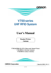
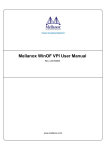
The proof of concept (POC) can divided into two phases.
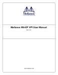
Phase 1—Two hosts connected to 10Gbps networking switch. This is scalable solution when more hosts are added.
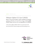
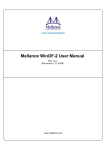
Phase 2—Two hosts connected back-to-back. This is a solution when a switch is not available for the infrastructre.
Below are the two configurations used for the purpose of validating NVGRE in Emulex Labs.
Figure 1. Two hosts connect to 10Gbps networking switch.
Figure 2. Host to Host connected back-to-back.
2
CO NNEC T | Configuring Windows Server 2012 R2 with NVGRE using the Emulex OCe14102 Adapter
CONNECT - APPLIC ATI O N N OTE
Hardware requirements
Hardware components
Quantity
Description
POC components
Server
2
Any server with Intel/AMD processors
which supports Windows 2012 R2
HP DL 380p Gen8 with Intel® Xeon®
CPU E5-2690 @ 2.90GHz
Hard drives
2
Any SAS or SATA drive
SAS 300GB drives
RAID controller
2
Any server with supports Windows 2012 R2
RAM
12-96GB/server
96GB RAM/server
OCe14102
2
Emulex 10GbE adapter with NVGRE offload
OCe14102
Switch
1
10Gbps switch
Cisco 5548P
Cables
2
10Gbps optical SFP+ cables
10Gbps optical SFP+ cables
Software requirements
Component
Quantity
Description
POC components
Windows 2012 R2 Server or DataCenter OS
2
License key and Windows 2012 R2 OS
Windows 2012 R2 DataCenter
Wireshark
1
Free Packet capturing and
analyzing tool for verification
Wireshark installed on one of the hosts
I/O Tools
a) Iometer
b) NTttcp
c) IxChariot
d) Medusa Labs Test Tools
e) Any other IO tool available within your organization
2
Iometer, NTttcp are free IO tools which
can be used for verification.
IxChariot and Medusa Labs Test Tool
requires a license.
Licensed IxChariot tool
Pre-installation
There are several steps to consider before applying power or installing an operating system on any system. First, you need to ensure rack
space and appropriate power and cooling are available. A key step is to ensure all hardware and software is at the latest firmware levels and
download any necessary patches and drivers.
As a best practice, updating the servers and converged network adapters to the latest firmware and drivers. For other components such as
LAN on motherboard (LOM) and integrated management ports, please refer to the server vendor website or user’s manual for the latest
firmware and driver.
The Emulex OCe14102 network adapter used the updated firmware and Windows 2012 R2 NIC driver. Please refer to Emulex for the latest
firmware and driver.
3
CO NNEC T | Configuring Windows Server 2012 R2 with NVGRE using the Emulex OCe14102 Adapter
CONNECT - APPLIC ATI O N N OTE
Post-installation
After installing Windows 2012 R2 Server or DataCenter on both the hosts along with Hyper-V role, name the hosts. For this POC, the hosts
have been named as “nvgre1” and “nvgre2”. Install at least two virtual machines (VMs) on each host. For this POC, the VMs have been
named as “Red1” and “Blue1” on nvgre1 and “Red2” and “Blue2” on nvgre2.
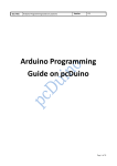
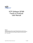
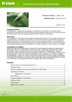
NVGRE offload should be enabled on the Emulex OCe14102 adapters. For verifying if the offload is enabled go to the OCe14102 adapter’s
Advanced Properties and verify the value to be “Enabled.”
Figure 3. Advanced Properties for Emulex OCe14102.
4
CO NNEC T | Configuring Windows Server 2012 R2 with NVGRE using the Emulex OCe14102 Adapter
CONNECT - APPLIC ATI O N N OTE
Phase 1: Two hosts connect to 10Gbps networking switch
Implementation/Configuration using an Emulex OCe14102 adapter
This POC was created using the modified version of simple and scalable multi-tenant topology demo script by Microsoft for Windows
2012. The script was modified for Windows 2012 R2. The key objective was to describe the configuration and validation of this multitenant topology with NVGRE.
Step 1—Configure the OCe14102’s IP address on Host1 and Host2
This section enlists the detailed steps followed in this POC for the configuring IP address on the OCe14102 adapter after installing the
latest firmware and driver.
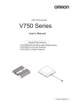
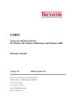
a) On “nvgre1,” go to the Server Manager; select Local Server from the console tree. Click the link next to EthernetX in the
Properties tile.
Figure 4. Server Manager.
b) In the Network Connections window, right-click EthernetX, and then click Properties.
Figure 5. Network connections.
5
CO NNEC T | Configuring Windows Server 2012 R2 with NVGRE using the Emulex OCe14102 Adapter
CONNECT - APPLIC ATI O N N OTE
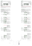
c) Click Internet Protocol Version 4 (TCP/IPv4), and then click Properties.
Figure 6. Ethernet properties.
d) Assign the IP address as 192.168.4.11 and Subnet mask as 255.255.255.0 and click OK.
Figure 7. TCP/IPv4 Properties.
e) Repeat the steps a through d on “nvgre2”: assign the IP address as 192.168.4.22 and the Subnet mask as 255.255.255.0.
6
CO NNEC T | Configuring Windows Server 2012 R2 with NVGRE using the Emulex OCe14102 Adapter
CONNECT - APPLIC ATI O N N OTE
Step 2—Modify or disable the firewall
This section enlists the step to disable the firewall. However, this might not be the case in a production enviroment. Depending on the
policy, please enable ping, I/O tool services and any other services required for enabling NVGRE policies.
a) Modfy or disable the host firewall according to the organization’s security policy.
b) For this POC, the firewall has been disabled on both the hosts.
Figure 8. Example to disable firewall.
Step 3—Configure a virtual switch on Host1 and Host2
This section enlists the steps to create, configure and assign a new virtual switch to the VMs
a) On “nvgre1,” from Server Manager, click the “Tools” and click “Hyper-V Manager.”
Figure 9. Hyper-V Manager.
7
CO NNEC T | Configuring Windows Server 2012 R2 with NVGRE using the Emulex OCe14102 Adapter
CONNECT - APPLIC ATI O N N OTE
b) Select the Virtual Switch Manager from the Actions pane.
Figure 10. Virtual switch Manager.
c) Create a new virtual switch by selecting “new virtual network switch.” Make sure “External” is selected for type of switch and
click OK.
Figure 11. Create a new virtual switch.
8
CO NNEC T | Configuring Windows Server 2012 R2 with NVGRE using the Emulex OCe14102 Adapter
CONNECT - APPLIC ATI O N N OTE
d) Name the virtual switch “NVGRE” and select the Emulex OCe14102 adapter from the drop-down menu of the external network.
Make sure the options “Allow management operating system to share this network adapter” and “Enable single-root I/O
virtualization” are not selected. Click on Apply.
Figure 12. Properties for the virtual switch.
e) Repeat steps a through d on “nvgre2.”
Step 4—Assign the network adapter for each VM and assign appropriate IP address to the interface for each VM.
a) Make sure the VM on “nvgre1” and “nvgre2” are turned OFF.
b) Click “Settings” from the Actions pane for each VM for “nvgre1.”
Figure 13. VM settings.
9
CO NNEC T | Configuring Windows Server 2012 R2 with NVGRE using the Emulex OCe14102 Adapter
CONNECT - APPLIC ATI O N N OTE
c) Under “Add Hardware” select “Network Adapter” and click on Add.
Figure 14. Add hardware.
d) Select the NVGRE Virtual Switch from the drop-down menu.
Figure 15. Add NVGRE as the new network adapter for each of the VM.
10
CO NNEC T | Configuring Windows Server 2012 R2 with NVGRE using the Emulex OCe14102 Adapter
CONNECT - APPLIC ATI O N N OTE
e) Expand the Network Adapter option and check for “Enable VMQ” under Hardware Acceleration.
Figure 16. Enable VMQ.
f)
Assign static MAC address under “Advanced Features.” Note that the Dynamic MAC address can be assigned too. Make sure each
VM has a unique MAC address on “nvgre1” and “nvgre2.”
Figure 17. Assign MAC address.
11
CO NNEC T | Configuring Windows Server 2012 R2 with NVGRE using the Emulex OCe14102 Adapter
CONNECT - APPLIC ATI O N N OTE
g) Turn ON each VM and assign an IP address to the interface using Network Manager or using netsh command.
Blue1: 10.0.0.3
Red1: 10.0.0.13
Note that the VM IP addresses can be the same as they are uniquely identified by VSID.
Figure 18. Set up IP addresses on the VM.
h) Repeat steps a through g for “nvgre2”. Use the following IP’s for VM on “nvgre2:”
Blue1: 10.0.0.9
Red1: 10.0.0.9
NOTE: For this POC, a separate 1Gpbs Management network and virtual switch was setup for remote access and for internet connectivity
purpose using the steps mentioned above.
Step 5—Test the network on the VM.
This section enlists the basic steps for validating the VM network before applying any NVGRE policies.
a) Ping Blue2 from Blue1 and Red1 from Red2 to ensure that the VM network is pingable.
b) If you cannot ping, make sure there is no firewall policies set on the host or the VM.
Step 6—Create powershell scripts to create lookup records.
This section enlists the details for the command to create lookup record policy entry for an IP address which belongs to a Microsoft®
Hyper-V® Server 2012 R2 virtual network.
a) Microsoft has a sample powershell script to create the NVGRE policy for Windows 2012.
However for this POC, as mentioned before, the script was modified for Windows 2012 R2.
b) Lookup records need to be created for each VM on every Hyper-V host as it creates a policy entry for an IP address in a virtual
network.
c) The command to create lookup records is “New-NetVirtualizationLookupRecord”.
Below are the listed parameters:
12
•
CustomerAddress: Specifies IP address of the VM.
•
ProviderAddress: Specifies IP address for a physical address that corresponds to the Customer Address.
•
VirtualSubnetID: Specifies numerical value representing the unique network.
•
MACAddress: Specifies MAC address of the VM guest without any “:”. For example: “000001170002.”
CO NNEC T | Configuring Windows Server 2012 R2 with NVGRE using the Emulex OCe14102 Adapter
CONNECT - APPLIC ATI O N N OTE
Use “Get-VMNetworkAdapter -VMName *” command to get all the MAC addresses for the VM
Figure 19. Sample output for “Get-VMNetworkAdapter-VMName *.”
•
Rule: Specifies which type of virtualization mechanism is being used. Use “TranslationMethodEncap” for NVGRE.
d) Create a powershell script named “Addpolicies_2vm.ps1” on “nvgre1” and “nvgre 2” and add the lines listed below to add the
Lookup record for VMs on “nvgre1” and “nvgre2:”
13
New-NetVirtualizationLookupRecord -VirtualSubnetID “5001” -CustomerAddress “10.0.0.3”
-ProviderAddress “192.168.4.11” -MACAddress “000001170002” -Rule “TranslationMethodEncap”
New-NetVirtualizationLookupRecord -VirtualSubnetID “5001” -CustomerAddress “10.0.0.9”
-ProviderAddress “192.168.4.22” -MACAddress “000002170002” -Rule “TranslationMethodEncap”
New-NetVirtualizationLookupRecord -VirtualSubnetID “6001” -CustomerAddress “10.0.0.13”
-ProviderAddress “192.168.4.11” -MACAddress “000001170012” -Rule “TranslationMethodEncap”
New-NetVirtualizationLookupRecord -VirtualSubnetID “6001” -CustomerAddress “10.0.0.19”
-ProviderAddress “192.168.4.22” -MACAddress “000002170012” -Rule “TranslationMethodEncap”
CO NNEC T | Configuring Windows Server 2012 R2 with NVGRE using the Emulex OCe14102 Adapter
CONNECT - APPLIC ATI O N N OTE
Step 7—Add customer routes
This section enlists the details for the command to create a virtual network route in Microsoft Hyper-V Server 2012 R2 virtual network.
a) The customer route must to be added on each Hyper-V host as it creates a virtual network route.
b) The command for adding customer route is “New-NetVirtualizationCustomerRoute.” Below are the parameters:
•
DestinationPrefix: Specifies destination VM address prefix.
•
NextHop: Specifies IP address for next hop gateway for the route.
•
RoutingDomainID: Specifies a unique identifier for the routing domain. It allows multiple virtual subnets.
•
Metric: Specifies an integer value for the route.
•
VirtualSubnetID: Specifies numerical value representing the unique network.
Note: Use the same value used in the previous add lookup record section.
c) Add the lines listed below to “Addpolicies_2vm.ps1”script on “nvgre1” and “nvgre 2” to add the customer route:
New-NetVirtualizationCustomerRoute -RoutingDomainID “{11111111-2222-3333-4444-000000005001}”
-VirtualSubnetID “5001” -DestinationPrefix “10.0.0.0/24” -NextHop “0.0.0.0” -Metric 255
New-NetVirtualizationCustomerRoute -RoutingDomainID “{11111111-2222-3333-4444-000000006001}”
-VirtualSubnetID “6001” -DestinationPrefix “10.0.0.0/24” -NextHop “0.0.0.0” -Metric 255
Step 8—Add Provider Address and Provider Route
This section enlists the details for the command to assign a Provider Address to a network interface for use in Microsoft Hyper-V Server
2012 R2 virtual network.
a) The provider address and provider route must be added, as it is unique to each host. It assigns a provider address to a network
interface and creates a provider route in the virtual network
b) The command for adding the provider address is “New-NetVirtualizationProviderAddress.” Below are the parameters:
•
InterfaceIndex: Specifies the interface index of the physical interface (OCe14102).
Get-netadapter commands gives the Interface Index.
Figure 20. Sample output for “Get-netadapter”.
14
•
ProviderAddress: Specifies the IP address configured for the OCe14102 adapter.
•
PrefixLength: Specifies the length of the IP prefix.
CO NNEC T | Configuring Windows Server 2012 R2 with NVGRE using the Emulex OCe14102 Adapter
CONNECT - APPLIC ATI O N N OTE
c) Add the lines listed below to “Addpolicies_2vm.ps1” script on “nvgre1” to add the Provider Address. Make sure to update the
Interface Index according to the output on the system:
New-NetVirtualizationProviderAddress -InterfaceIndex 34 -ProviderAddress 192.168.4.11
-PrefixLength 24
d) Add the lines listed below to “Addpolicies_2vm.ps1” script on “nvgre2” to add the Provider Address. Make sure you update the
Interface Index according to the output on the system:
New-NetVirtualizationProviderAddress -InterfaceIndex 24 -ProviderAddress 192.168.4.22
-PrefixLength 24
e)
The command for adding Provider Route is “New-NetVirtualizationProviderRoute”. Below are the parameters:
•
InterfaceIndex: Specifies the interface index of the physical interface (OCe14102).
Get-netadapter command gives the Interface ID.
Figure 21. Sample output for “Get-netadapter”.
•
DestinationPrefix: Specifies destination VM address prefix
•
NextHop: Specifies IP address for next hop gateway for the route
•
Metric: Specifies an integer value for the route.
f)
Add the lines listed below to “Addpolicies_2vm.ps1” script on “nvgre1” to add the Provider route. Make sure to update the
Interface Index according to the output on the system:
New-NetVirtualizationProviderRoute -DestinationPrefix “10.0.0.0/24” -InterfaceIndex 34 -NextHop
“0.0.0.0” -Metric 255
g) Add the lines listed below to “Addpolicies_2vm.ps1” script on “nvgre2” to add the provider route. Make sure to update the
Interface Index according to the output on the system:
New-NetVirtualizationProviderRoute -DestinationPrefix “10.0.0.0/24” -InterfaceIndex 24 -NextHop
“0.0.0.0” -Metric 255
Step 9—Add VirtualSubnetID on the VMs’ network port
This section enlists the details for assigning an unique VirtualSubnet ID for each VM.
a) Add the lines listed below to “Addpolicies_2vm.ps1” script on “nvgre1” to add the virtualSubnetID to VM network port:
Get-VMNetworkAdapter “Blue1” | where {$_.MacAddress -eq “000001170002”} | Set-VMNetworkAdapter
-VirtualSubnetID 5001
Get-VMNetworkAdapter “Red1” | where {$_.MacAddress -eq “000001170012”} | Set-VMNetworkAdapter
-VirtualSubnetID 6001
b) Add the lines listed below to “Addpolicies_2vm.ps1” script on “nvgre2” to add the virtualSubnetID to VM network port:
15
Get-VMNetworkAdapter “Blue2” | where {$_.MacAddress -eq “000002170002”} | Set-VMNetworkAdapter
-VirtualSubnetID 5001;
Get-VMNetworkAdapter “Red2” | where {$_.MacAddress -eq “000002170012”} | Set-VMNetworkAdapter
-VirtualSubnetID 6001;
CO NNEC T | Configuring Windows Server 2012 R2 with NVGRE using the Emulex OCe14102 Adapter
CONNECT - APPLIC ATI O N N OTE
Step 10—Run the script and verify the configuration
This section enlists the details running the script on each host and validating if the policy is set correctly.
a) Run the script on “nvgre1” and “nvgre2.”
b) Run the following commands on “nvgre1” and “nvgre2” and make sure all the MAC addresses, IP addresses, VSID, Customer
Route, Provider Route are set correctly.
Get-NetVirtualizationProviderAddress
Figure 22. Sample output for “Get-NetVirtualizationProviderAddress.”
Get-NetVitrualizationProviderRoute
Figure 23. Sample output for “Get-NetVirtualizationProviderRoute.”
16
CO NNEC T | Configuring Windows Server 2012 R2 with NVGRE using the Emulex OCe14102 Adapter
CONNECT - APPLIC ATI O N N OTE
Get-NetVirtualizationLookupRecord
Figure 24. Sample output for “Get-NetVirtualizationLookupRecord.”
Get-NetVirtualizationCustomerRoute
Figure 25. Sample output for “Get-NetVirtualizationCustomerRoute.”
17
CO NNEC T | Configuring Windows Server 2012 R2 with NVGRE using the Emulex OCe14102 Adapter
CONNECT - APPLIC ATI O N N OTE
c) Turn ON the VMs on “nvgre1” and “nvgre2.
d) Ping Blue2 from Blue1 and Red1 from Red2 to ensure that the VM network is pingable.
Figure 26. Sample output for working ping.
18
CO NNEC T | Configuring Windows Server 2012 R2 with NVGRE using the Emulex OCe14102 Adapter
CONNECT - APPLIC ATI O N N OTE
Setup verification
After the basic network validation is performed ensuring that the NVGRE policies were set correctly, we can use any I/O tool to validate the
multi-tenant topology.
a.
Netperf, IOMeter or any IO tool can be used to verify the test setup.
b.
Create a script using IxChariot I/O tool with the all the endpoint details. See the IxChariot Guide on how to create the test scripts.
c.
For this POC, ultra high performance throughput script was used with 32 threads for each VM.
Figure 27. Sample script for IxChariot.
19
CO NNEC T | Configuring Windows Server 2012 R2 with NVGRE using the Emulex OCe14102 Adapter
CONNECT - APPLIC ATI O N N OTE
d.
Run the script to make sure the I/O run is successful.
Figure 28. Sample successful I/O output.
20
CO NNEC T | Configuring Windows Server 2012 R2 with NVGRE using the Emulex OCe14102 Adapter
CONNECT - APPLIC ATI O N N OTE
e.
Please refer to Wireshark for detailed steps on how to capture packet. This is an optional step for verification.
f.
Wireshark was used to capture some of the packets to take a look at the contents. On the capture for NVGRE enabled,
“Generic Routing Encapsulation (Transparent Ethernet Bridging)” header was seen in the Ethernet packet.
g.
For traffic with no NVGRE policy, no Generic Routing Encapsulation (Transparent Ethernet Bridging)” header was seen in the
Ethernet packet.
Figure 29. Sample wireshark captures.
21
CO NNEC T | Configuring Windows Server 2012 R2 with NVGRE using the Emulex OCe14102 Adapter
CONNECT - APPLIC ATI O N N OTE
Remove NVGRE policy
If there are any changes required to the existing configuration, like adding/removing any VM or changing any MAC address or changing
VSID, we need to remove the existing policy before enabling the new changes. Please make sure the VMs are shut down before executing
the remove policy script.
1.
To remove the NVGRE policy, create a RemovePolicy.ps1 script on “nvgre1” and “nvgre2.”
2.Add “Remove-NetVirtualizationCustomerRoute,” “Remove-NetVirtualizationLookupRecord,” “Remove-NetV
irtualizationProviderAddress,” “Remove-NetVirtualizationProviderRoute” to RemovePolicy.ps1 script for both
the hosts.
3.
Assign “0” to VSID to each VM on both the hosts.
4.
Add the lines below to RemovePolicy.ps1 on nvgre1.
Get-VMNetworkAdapter “Blue1” | where {$_.MacAddress -eq “000001170002”} | Set-VMNetworkAdapter
-VirtualSubnetID 0
Get-VMNetworkAdapter “Red1” | where {$_.MacAddress -eq “000001170012”} | Set-VMNetworkAdapter
-VirtualSubnetID 0
5.
Add the lines below to RemovePolicy.ps1 on nvgre2.
Get-VMNetworkAdapter “Blue2” | where {$_.MacAddress -eq “000002170002”} | Set-VMNetworkAdapter
-VirtualSubnetID 0
Get-VMNetworkAdapter “Red2” | where {$_.MacAddress -eq “000002170012”} | Set-VMNetworkAdapter
-VirtualSubnetID 0
6.
Shutdown all the VMs and then run the script on each host.
Phase 2—Two hosts connected back to back
The steps for this phase are exactly the same as Phase1. If a 10Gbps switch is not available for implementing the NVGRE feature, this phase
can be implemented instead of phase 1.
Conclusion
In summary, the overview of the hardware and software components needed to successfully deploy a NVGRE configuration was
introduced as a part of this application note. As it can be seen, configuring and deploying NVGRE on a Windows Server 2012 R2 with the
Emulex OCe14102 adapter is fairly simple. The steps and powershell commands go hand-in-hand for deployment. When evaluating the
deployment, it is important to understand the method used for configuration and the environment where it is deployed. Please refer to
Microsoft for detailed deployment steps of Hybrid Cloud with NVGRE using VMM.
22
CO NNEC T | Configuring Windows Server 2012 R2 with NVGRE using the Emulex OCe14102 Adapter
CONNECT - APPLIC ATI O N N OTE
Appendix A: NVGRE policy powershell script used for the above configuration
################################################################################################
#################
# Blue Virtual Network Information
#
# RoutingDomainID=”{11111111-2222-3333-4444-000000005001}”
# VirtualSubnetID]=5001
# (Both RDID and VSID are defined by administrators, MUST be unique in the datacenter)
#
# [Customer Addresses]
# VM Name Host VSID CA PA MAC DefaultGW
# --------------------------------------------------------------------------------# Blue1 Host1 5001 10.0.0.3 192.168.4.11 00-00-01-17-00-02 10.0.0.1
# Blue2 Host2 5001 10.0.0.9 192.168.4.22 00-00-02-17-00-02 10.0.0.1
#
# [Customer Routes]
# DestPrefix NextHopGW Note
# 10.0.1.0/24 0.0.0.0 Onlink route for Blue subnet
# Add the locator records for Blue subnet
New-NetVirtualizationLookupRecord -VirtualSubnetID “5001” -CustomerAddress “10.0.0.3”
-ProviderAddress “192.168.4.11” -MACAddress “000001170002” -Rule “TranslationMethodEncap”
New-NetVirtualizationLookupRecord -VirtualSubnetID “5001” -CustomerAddress “10.0.0.9”
-ProviderAddress “192.168.4.22” -MACAddress “000002170002” -Rule “TranslationMethodEncap”
# Add the customer route records for Blue subnet
New-NetVirtualizationCustomerRoute -RoutingDomainID “{11111111-2222-3333-4444-000000005001}”
-VirtualSubnetID “5001” -DestinationPrefix “10.0.0.0/24” -NextHop “0.0.0.0” -Metric 255
################################################################################################
#################
#Red Virtual Network Information
#
# RoutingDomainID=”{11111111-2222-3333-4444-000000006001}”
# VirtualSubnetID=6001
# (Both RDID and VSID are defined by administrators, MUST be unique in the datacenter)
#
# [Customer Addresses]
23
CO NNEC T | Configuring Windows Server 2012 R2 with NVGRE using the Emulex OCe14102 Adapter
CONNECT - APPLIC ATI O N N OTE
# VM Name Host VSID CA PA MAC DefaultGW
# ------------------------------------------------------------------------------------------# Red1 Host1 6001 10.0.0.13 192.168.4.11 00-00-01-17-00-12 10.0.0.1
# Red2 Host2 6001 10.0.0.19 192.168.4.22 00-00-02-17-00-12 10.0.0.1
# [Customer Routes]
# DestPrefix NextHopGW Note
# 10.0.0.0/24 0.0.0.0 Onlink route for Red subnet
# Add the locator records for Red subnet
New-NetVirtualizationLookupRecord -VirtualSubnetID “6001” -CustomerAddress “10.0.0.13”
-ProviderAddress “192.168.4.11” -MACAddress “000001170012” -Rule “TranslationMethodEncap”
New-NetVirtualizationLookupRecord -VirtualSubnetID “6001” -CustomerAddress “10.0.0.19”
-ProviderAddress “192.168.4.22” -MACAddress “000002170012” -Rule “TranslationMethodEncap”
# Add the customer route records for Red subnet
New-NetVirtualizationCustomerRoute -RoutingDomainID “{11111111-2222-3333-4444-000000006001}”
-VirtualSubnetID “6001” -DestinationPrefix “10.0.0.0/24” -NextHop “0.0.0.0” -Metric 255
################################################################################################
#################
# [2] Configure the Host Provider Addresses and Routes required for this setup
# [Host PA Address & Route information required by the VM policy]
# Host Hostname {PA’s} {VM:VirtualSubnetID} ==> Set on the VMNetworkAdapter on each host
# ------------------------------------------------------------------------------------------------------------------------# Host1 example-host1 192.168.4.11 {Blue1:5001, Red1:6001}
# Host2 example-host2 192.168.4.22 {Blue2:5001, Red2:6001}
# [2-2] Host2
# (a) Configure Provider Address and Route:
#Get-NetAdapter
New-NetVirtualizationProviderAddress -InterfaceIndex 34 -ProviderAddress 192.168.4.11
-PrefixLength 24
# (b) Set VirtualSubnetID on the VM network port
Get-VMNetworkAdapter “Blue1” | where {$_.MacAddress -eq “000001170002”} | Set-VMNetworkAdapter
-VirtualSubnetID 5001
Get-VMNetworkAdapter “Red1” | where {$_.MacAddress -eq “000001170012”} | Set-VMNetworkAdapter
-VirtualSubnetID 6001
# ProviderRoute
New-NetVirtualizationProviderRoute -DestinationPrefix “10.0.0.0/24” -InterfaceIndex 34 -NextHop
“0.0.0.0” -Metric 255
24
CO NNEC T | Configuring Windows Server 2012 R2 with NVGRE using the Emulex OCe14102 Adapter
CONNECT - APPLIC ATI O N N OTE
Appendix B: NVGRE policy removal powershell script used for the above configuration
Get-NetVirtualizationCustomerRoute
Get-NetVirtualizationGlobal
Get-NetVirtualizationLookupRecord
Get-NetVirtualizationProviderAddress
Get-NetVirtualizationProviderRoute
Remove-NetVirtualizationCustomerRoute
Remove-NetVirtualizationLookupRecord
Remove-NetVirtualizationProviderAddress
Remove-NetVirtualizationProviderRoute
Get-VMNetworkAdapter “Blue1” | where {$_.MacAddress -eq “000001170002”} | Set-VMNetworkAdapter
-VirtualSubnetID 0
Get-VMNetworkAdapter “Red1” | where {$_.MacAddress -eq “000001170012”} | Set-VMNetworkAdapter
-VirtualSubnetID 0
Get-NetVirtualizationCustomerRoute
Get-NetVirtualizationGlobal
Get-NetVirtualizationLookupRecord
Get-NetVirtualizationProviderAddress
Get-NetVirtualizationProviderRoute
25
CO NNEC T | Configuring Windows Server 2012 R2 with NVGRE using the Emulex OCe14102 Adapter
CONNECT - APPLIC ATI O N N OTE
More information
The Implementer’s Lab website
www.implementerslab.com
Hyper-V Network Virtualization technical details
http://technet.microsoft.com/enus/library/jj134174.aspx
Simple Hyper-V Network Virtualization Demo script
http://gallery.technet.microsoft.com/scriptcenter/Simple-Hyper-V-Network-d3efb3b8
Hyper-V Network Virtualization Gateway Architectural Guide
http://technet.microsoft.com/en-us/library/jj618319.aspx
Simple Hyper-V Network Virtualization Script with Gateway
http://gallery.technet.microsoft.com/scriptcenter/Simple-Hyper-V-Network-6928e91b
NVGRE IETF draft
http://tools.ietf.org/html/draft-sridharan-virtualization-nvgre-02
To help us improve our documents, please provide feedback at
[email protected]
Some of these products may not be available in the U.S. Please contact your supplier for more information.
World Headquarters 3333 Susan Street, Costa Mesa, CA 92626 +1 714 662 5600
Bangalore, India +91 80 40156789 | Beijing, China +86 10 84400221
Dublin, Ireland +35 3 (0) 1 652 1700 | Munich, Germany +49 (0) 89 97007 177
Paris, France +33 (0) 158 580 022 | Tokyo, Japan +81 3 5325 3261 | Singapore +65 6866 3768
Wokingham, United Kingdom +44 (0) 118 977 2929 | Brazil +55 11 3443 7735
ww w.emu l ex .c o m
©2014 Emulex, Inc. All rights reserved.
This document refers to various companies and products by their trade names. In most cases, their respective companies claim these designations as trademarks or registered trademarks. This information is provided for reference only. Although this information is
believed to be accurate and reliable at the time of publication, Emulex assumes no responsibility for errors or omissions. Emulex reserves the right to make changes or corrections without notice. This document is the property of Emulex and may not be duplicated
without permission from the Company.
ELX15-2020 · 9/14