1
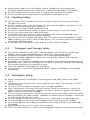
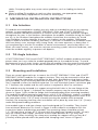
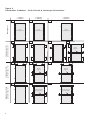
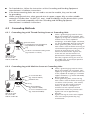
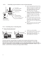
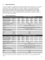
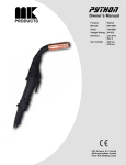
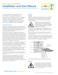
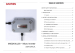
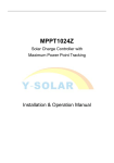
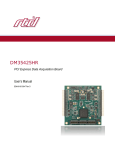
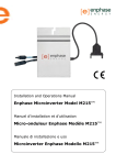
Installation And User Manual
SCHOTT PERFORM™ POLY
SCHOTT PERFORM™ MONO
PLEASE READ THIS MANUAL
BEFORE INSTALLING OR USING THE
MODULES
This manual contains important safety instructions
that must be followed during the installation and
maintenance of the SCHOTT PERFORM™ POLY and
SCHOTT PERFORM™ MONO Photovoltaic (PV) Modules.
Failure to follow these instructions may result in bodily
injury or damage to property. Working on a photovoltaic
system requires
specialized knowledge and should only be performed
by qualified professionals.
Introduction
Thank you for choosing SCHOTT PERFORM™ POLY and
SCHOTT PERFORM™ MONO PV modules. With over 50
years of experience in the production of photovoltaic
products, SCHOTT is committed to producing high quality products that will last for over 25 years. Please review
this manual before installing the PV modules. These
instructions must be kept with the documentation for
the solar system in which the PV modules are installed.
This manual does not constitute a warranty,
expressed or implied. SCHOTT Solar does not take
responsibility and disclaims any liability for loss,
damage or expense arising out of or in any way
connected with installation, operation, use or
maintenance of PV modules. No responsibility is
assumed by SCHOTT Solar for any infringement of
patents or other rights of third parties that may
result from the use of PV modules.
SCHOTT Solar reserves the right to make changes to
the product, specifications or installation manual
without prior notice.
Manufacturer:
SCHOTT Solar PV, Inc.
5201 Hawking Drive, SE
Albuquerque, NM 87106
01/2012
SCHOTT reserves the right to make
amendments
© 2012 SCHOTT Solar Inc
Installation And User Manual
SCHOTT PERFORM™ POLY Photovoltaic Modules
SCHOTT PERFORM™ MONO Photovoltaic Modules
SCHOTT
SCHOTT
SCHOTT
SCHOTT
SCHOTT
PERFORM™
PERFORM™
PERFORM™
PERFORM™
PERFORM™
POLY 220, SCHOTT PERFORM™ POLY 225,
POLY 230, SCHOTT PERFORM™ POLY 235,
POLY 240, SCHOTT PERFORM™ POLY 245
MONO 245, SCHOTT PERFORM™ MONO 250
MONO 255
Contents
1. WARNING NOTICES
2. SAFETY
2.1
General Safety
2.2
Handling Safety
2.3
Transport and Storage Safety
2.4
Installation Safety
3. MECHANICAL INSTALLATION INSTRUCTIONS
3.1
Site Selection
3.2
Tilt Angle Selection
3.3
Mounting and Installation
4. ELECTRICAL INSTALLATION INSTRUCTIONS
4.1
Grounding Overview
4.2
Grounding Methods
4.2.1 Grounding Lug with Thread-Cutting Screw at Grounding Hole
4.2.2 Grounding Lug with Machine Screw at Grounding Hole
4.2.3 Grounding Lug with Machine Screw at Mounting Hole
4.2.4 Grounding Clip at Grounding Hole
5. MAINTENANCE
6. SPECIFICATIONS
4
4
5
5
5
5
6
6
6
6
10
10
12
12
12
12
12
13
13
3
1
WARNING NOTICES
Danger of Death from Electric Shock
Photovoltaic modules generate electricity when exposed to light. The maximum voltage
from a single module when exposed to light is less than 50 VDC. However, when
connected in series, the total voltage adds up and can be dangerously high. When the
modules are connected in parallel, the current adds up and can be dangerous. When
handling a PV module, following instructions must be practiced to avoid risk of arc
formation, fire and electric shock.
쮿 Only qualified & trained personnel should install a PV module.
쮿 Do not wear metallic jewelry during installation.
쮿 Do not install PV modules during wet conditions. Use only dry tools.
쮿 Do not use damaged or defective modules. All damaged or defective modules should
be stored in a carton to avoid exposure to light. Even damaged or defective modules
can produce electricity
쮿 Use caution when in contact with electrically active parts of a PV module such as
terminals. There is always risk of burns, sparks and lethal shock even if the PV modules
are not connected. PV systems can produce high voltage and current which could
cause serious injury or death
쮿 Do not expose PV modules to light concentrated with mirrors, lenses or other means.
쮿 Use appropriate safety equipment (insulated tools, insulated gloves, etc) when working
on wiring
The inverter can produce dangerously high voltage
Be sure to follow all manufacturers’ instructions before installing any PV modules.
Use extreme caution when wiring or installing inverter.
Be sure to shut down inverter before installing or removing PV modules.
쮿
쮿
쮿
When exposed to light, PV modules produce direct current. When disconnecting PV
modules from a string, deadly arcing can occur.
쮿 Never remove a PV module without disconnecting the inverter from the grid
쮿 Never remove the PV module without disconnecting the PV system from the inverter.
쮿 Make sure that the connectors are in good working condition and are properly
connected to each other.
2
2.1
SAFETY
General Safety
All PV modules should be installed in accordance with applicable codes and regulations,
including , but not limited to the National Electrical Code (NEC)
쮿 Roof mounted PV modules should be mounted on a fire resistant roof.
쮿 Only PV modules with the same cell type and size should be connected in series.
쮿 Follow all safety precautions for other components used in the system.
쮿
4
Avoid uneven shade on the PV module surface. Shaded cells may become hot
(“hotspot” phenomenon) which may result in permanent damage of the module.
쮿 Do not use high pressure water spray or chemicals to clean the PV modules.
쮿 Turn off inverters and circuit breakers immediately if a problem occurs.
쮿
2.2
쮿
쮿
쮿
쮿
쮿
쮿
쮿
쮿
Do not expose the PV module to excessive loads on the surface or twist the frame.
The glass may break.
Do not stand or step on the PV module. The glass may be slippery, and there is a risk
of injury or electric shock if glass is broken.
PV modules are heavy. Please handle with care.
Do not hit or put excessive load on the glass or back sheet. PV cells may break.
Do not twist the interconnect cable excessively.
Do not drill holes in the frame. It may compromise the frame strength and cause
corrosion of the frame and will void the warranty.
Do not touch the PV module with bare hands. The frame of the PV module has sharp
edges and may cause injury. Wear suitable gloves, such as leather gloves with padding
in the palm and finger areas.
Do not drop the PV module or allow objects to fall on the PV module.
2.3
쮿
쮿
쮿
쮿
쮿
쮿
쮿
쮿
쮿
쮿
쮿
쮿
쮿
쮿
쮿
쮿
Transport and Storage Safety
Store the PV modules in a dry place. The packaging is not resistant to weathering.
Modules must not be exposed directly to water (e.g. rain) during storage.
Transport the modules to the installation site in the original packaging.
Protect the module cables from mechanical stress during transport and assembly.
Do not pull on the cables.
Particularly when lifting the modules from the pallets, ensure that the modules are not
pulled down at a slant over the edges of the frame. Photovoltaic modules with backing
foil are particularly prone to mechanical stress.
Check the modules for damage after unpacking.
Do not install or commission damaged modules. Report any damage to the supplier
immediately.
2.4
쮿
Handling Safety
Installation Safety
Always wear protective head gear, insulating gloves and safety shoes (with rubber
soles).
Due to the risk of electrical shock, do not perform any work if the terminals of the PV
module are wet.
Do not install PV modules in the rain, snow or windy conditions
Insert interconnect connectors fully and correctly. Check all connections. Secure the
cables to the PV module frames, support structure or raceway to prevent movement.
Keep connectors out of direct sunlight.
Do not touch the terminal box and the end of the interconnect cables with bare hands
during installation or under sunlight, regardless of whether the PV module is connected
to or disconnected from the system.
Do not unplug a connector if the system circuit is connected to an operating load.
Do not damage the back sheet of PV modules when mounting the PV modules.
Do not damage the surrounding PV modules or mounting structure when replacing a
PV module.
Keep children away from the system while installing.
Use UV resistant cable ties or other wire management hardware to secure inter-connect
5
cables. Drooping cables may cause various problems, such as leading to electrical
shorts.
쮿 When installing PV modules on roofs or other structures, use appropriate safety
practices and safety equipment at all times to avoid injury.
3 MECHANICAL INSTALLATION INSTRUCTIONS
3.1
Site Selection
PV modules are intended for outdoor use only and not intended for use on any moving
vehicles. In most applications SCHOTT PERFORM™ POLY and SCHOTT PERFORM™
MONO modules should be installed in a location where they receive maximum sunlight
throughout the year. In the Northern Hemisphere the modules should be facing the southern sky; in the Southern Hemisphere the modules should face the northern sky. Avoid
trees, buildings or other obstacles that can cast shadows on the modules. Take proper
steps in order to maintain reliability and safety in case the PV modules are installed in areas
that have heavy snow, extreme cold, strong winds, salt water exposure, or heavy dust. If
you are planning to use the PV modules in marine environments, ensure that there is no
direct salt water contact, use corrosion resistant mounting system/ electrical hardware, and
clean the modules regularly to prevent salt deposits.
3.2
Tilt Angle Selection
SCHOTT PERFORM™ POLY and SCHOTT PERFORM™ MONO modules produce maximum
power when sun’s rays strike the module perpendicular to the module surface. To avoid
performance losses in series circuits, ensure that all modules have the same tilt and orientation. Your solar professional will be able to determine the best tilt angle for your location.
3.3
Mounting and Installation
There are several approved ways to mount the SCHOTT PERFORM™ POLY and SCHOTT
PERFORM™ MONO modules to a support structure. They may be mounted in either portrait or landscape orientation using either the bolt holes provided or using frame clamps
(not provided). For all mounting methods a minimum gap of 1/4” (7 mm) between modules is required to allow for thermal expansion. For roof mounted systems a minimum gap
of 1” between the module and the roof surface is required to allow for ventilation.
The modules may be fastened to a support using the bolt holes in the rear flange of the
frame as shown in Figure 1. If desired, the fastener sequence may be reversed from that
shown in Figure 1 (Nut inside the flange, bolt head protruding from mounting member).
The module should be fastened at four points, with a 5/16” (M8) bolt, washers, including
a lock washer and a nut (not provided). Note that the four mounting positions must lie in
the same plane within 1/8” (3 mm) to avoid stressing the module when mounted.
Similarly, the mounting structure must not deflect out of plane by more than 1/8” (3 mm)
under anticipated loading conditions.
Inter-module type or end-type clamps must be designed for PV modules. They should
have minimum dimensions as shown in Figure 2 and installed in accordance with the
instructions below and drawings provided. The mounting clamps should be at least
1.5” (38 mm) long, at least 0.12” (3 mm) thick (for aluminum clamps) or 0.08” (2 mm)
thick for stainless steel clamps, and have a catch width between 0.2” (5 mm) and
0.3” (8 mm). When installing, the clamp must overlap the support rail by at least 0.4”
(10 mm) and be placed within the permissible clamping zones shown in Figure 3.
6
Do not overtighten clamps as the glass may be damaged.
For the high load situations shown in Figure 3 an additional center support rail should be
used. The center support should be attached to the mounting members with the rear
flange of the module in contact with it. Attachment of the module to the center support is
not necessary. Note that SCHOTT does not warranty frame clamps. The SCHOTT module
warranty may be void if customer-selected frame clamps are improper or inadequate with
respect to properties (including strength or material) or installation.
Figure 1:
Figure 2:
1.5” min.
catch length
5/16” (M8) bolt
washer
0.2” min.
catch width
Clamp
washer
spring washer
0.4” min.
support widht
Support Rail
5/16” (M8) nut
Attachment Using Mounting Holes
0.12” min.
thickness
Attachment Using Clamps
7
Figure 3:
Attachment Guidelines – Both Portrait & Landscape Orientations
< 54 Ib/Ft2
(< 2400 Pa)
1/2
Use all
mounting holes
1/3
Use all
mounting holes
2/2
2/3
1/8 L
Clamping, Long Side
(permissible clamp zone)
1/4 L
2/1
2/4
1/4 W
3/3
1/4 W
1/4 L
1/4 W
Center
Support
4/2
4/3
Center Support
(portrait only)
Center Support
(portrait only)
16”
4/1
8”
16”
Center
Support
1/4 W
8”
3/2
Clamping, Short Side
(permissible clamp zone)
1/4 W
2”
1/4 L
1/8 L
8”
Center
Support
3/1 1/4 W
Clamping, Insert System
(permissible clamp zone)
Use all
mounting holes
2”
Mounting Holes
1/1
8
< 75 Ib/Ft2
(< 3600 Pa)
1/4 L
< 33 Ib/Ft2
(< 1600 Pa)
9
50/1.97”
frame proile
2x grounding hole
Ø 4,25
993/39.09”
Figure 4:
Module Geometry, Mounting and Grounding Holes
1685/66.34”
1,100/43.3”
572.5/22.5”
4x mounting hole Ø 9
437.5/17.2”
810/31.9”
437.5/17.2”
4 ELECTRICAL INSTALLATION INSTRUCTIONS
All SCHOTT PERFORM™ POLY and SCHOTT PERFORM™ MONO modules are pre-wired with
(2) Tyco 4 mm2 PV1-F 90°C UL listed wire and terminated with Tyco Solarlock connectors.
The wire is intended for interconnection wiring of grounded and ungrounded photovoltaic
power systems as described in the National Electical Code, Section 690.31(A). MINUS is
marked on connector, POSITIVE is not marked. Make sure that all connections are not
under load while being connected. Care must be taken to arrange the system ground so
that the removal of one module will not interrupt the grounding of any other modules.
Under no circumstances should the junction box be opened. Series and parallel connections
shall be made by using #10 (or 4 mm2) AWG 90°C type sunlight resistant output cables (or
equivalent) with Male and Female Tyco™ locking connectors. Locking ring maybe required
to comply with NEC 2008.
Tyco mating connector part numbers
Wire Size
Polarity
Gender
Tyco Part Number
4.0 mm²/12 AWG
+
Female
4-1394462-8
6.0 mm²/10 AWG
+
Female
6-1394462-3
4.0 mm²/12 AWG
Neutral
Male
7-1394461-2
6.0 mm²/10 AWG
Neutral
Male
7-1394461-5
Select a suitable conductor diameter to minimize voltage drop. Conductors should be
between 8-14 AWG (1.5-10 mm2) USE-2 (non conduit) THWN-2 (conduit) or check with
your Solar professional to determine correct conductor sizing or wire. Over current
protection shall be in accordance to NEC 240.
NOTE: MAXIMUM SYSTEM VOLTAGE IS 600 VDC. All installations, string sizing and
electrical connections should be designed to meet the relevant NEC codes. A qualified solar
professional should refer to the National Electrical Code 690-7(a) to determine the maximum
number of SCHOTT POLY™ and SCHOTT PERFORM™ MONO modules that can be placed
in series. Under normal conditions, a photovoltaic module is likely to experience conditions
that produce more current and/or voltage than reported at standard test conditions.
Accordingly, the values of Isc and Voc marked on this module should be multiplied by a factor of 1.25 when determining
component voltage ratings, conductor ampacities, fuses and the size of controls connected
to the PPV output. Refer to section 690-8 of the National Electrical Code for an additional
multiplying factor of 125 percent (80% derating) which may be applicable.
4.1
Grounding Overview
Several different methods of grounding can be used to provide the required connection
through the frame anodizing. Before installation contact the local code Authority Having
Jurisdiction (AHJ) to determine the proper grounding requirements. Attach all module frames to
an earth ground in accordance with applicable articles of the National Electrical Code (NEC),
250 and 690.
10
쮿
쮿
쮿
4.2
For listed devices, follow the instructions of the Grounding and Bonding Equipment
manufacturer’s installation instructions.
If the frame mounting holes are not used to secure the module, they can be used
for grounding.
When using ground wire, select ground wire of copper, copper alloy or other suitable
material no smaller than 14 AWG (2.1 mm), sized accordingly for the photovoltaic system
per NEC, and sized compatibly with the Grounding and Bonding Equipment
manufacturer’s installation instructions.
Grounding Methods
4.2.1 Grounding Lug with Thread-Cutting Screw at Grounding Hole
쮿
module frame
~20
in-lbs
SS #10 External Serrated Washer
(e.g. McMaster 91120A140)
Lug
쮿
SS 10-32 X 1/2 Thread-Cutting Screw
(e.g. Fastenal 11112837)
copper wire
#4-6 at 35 in-lbs
#8 at 25 in-lbs
#10-14 at 20 in-lbs
Select a grounding lug listed for direct
burial and outdoor use (tin-plated, solid
copper lay-in lug with a stainless-steel set
module frame screw) capable of
accepting a 4-14 AWG copper conductor,
e.g. ILSCO GBL4-DBT, Burndy CL50-1TN.
To the grounding hole, secure the lug
with stainless steel hardware consisting of
a thread-forming/thread-cutting screw of
at least 32 threads per inch and an
external serrated washer. Tighten the
screw until the serrated washer has
penetrated the frame (approximately
20 in-lbs). Tighten the lug set screw to
the copper wire at the torque specified
by lug manufacturer.
4.2.2 Grounding Lug with Machine Screw at Grounding Hole
쮿
SS 8-32 K-Lock Nut
(e.g. Fastenal 70922)
module frame
쮿
Lug
~20
in-lbs
copper wire
#4-6 at 35 in-lbs
#8 at 25 in-lbs
#10-14 at 20 in-lbs
SS #8 Flat Washer
(e.g. Fastenal 71008)
SS 8-32 x 1 Machine Screw
(e.g. Fastenal 0170682)
쮿
Select a grounding lug listed for direct
burial and outdoor use (tin-plated, solid
copper lay-in lug with a stainless-steel set
screw) capable of accepting a 4-14 AWG
copper conductor, e.g. ILSCO GBL4-DBT,
Burndy CL50-1TN.
To the grounding hole, secure the lug
with stainless steel hardware consisting of
a machine screw (min#8), a flat washer,
and a lock nut with integral serrated
washer, as shown in the figure. A
standard nut with separate external
serrated lock washer may also be used.
Tighten the nut to approximately
20 in-lbs.
Tighten the lug set screw to the copper
wire at the torque specified by lug
manufacturer.
11
4.2.3
Grounding Lug with Machine Screw at Mounting Hole
쮿
SS 8-32 Nut
(e.g. Fastenal 70706)
SS #8 Flat Washer
(e.g. Fastenal 71008)
쮿
module frame
Lug
~20
in-lbs
copper wire
#4-6 at 35 in-lbs
#8 at 25 in-lbs
#10-14 at 20 in-lbs
SS #8 Flat Washer
(e.g. Fastenal 71008)
SS 8-32 x 1 Machine Screw
(e.g. Fastenal 0170682)
쮿
쮿
Select a grounding lug listed for direct
burial and outdoor use (tin-plated, solid
copper lay-in lug with a stainless-steel
set screw) capable of accepting a 4-14
AWG copper conductor, e.g. ILSCO
GBL4-DBT, Burndy CL50-1TN.
Use an emery cloth, sandpaper, or a
steel brush to remove the anodizing
coating on the frame. The area removed
should be the same size as the lug
mating face. Apply an anti-oxidation
coating, e.g. Burndy Penetrox, Ideal
Noalox.
To the mounting hole, secure the lug
with stainless steel hardware consisting
of a machine screw (min#8), two flat
washers, and a nut, as shown in the
figure. Tighten the nut to approximately
20 in-lbs.
Tighten the lug set screw to the copper
wire at the torque specified by lug
manufacturer.
4.2.4 Grounding Clip at Grounding Hole
쮿 Select a grounding clip listed and
designed to ground photovoltaic
~20
in-lbs
8-32 screw
and hex nut
~20
in-lbs
쮿
10-32 thread
cutting screw
쮿
modules, e.g. TYCO SolKlip.
To the grounding hole, secure the clip
per manufacturer’s instructions and
tighten the screw to 20 in-lbs.
Insert copper wire into the wire slot
per manufacturer’s instructions.
4.2.5 Alternate Grounding Methods
Alternate methods of grounding the module may be permissible based on testing
performed by mounting structure manufacturer or other third parties. Consult the
manufacturer for details and certifications for such alternate methods. For any method,
the user must ensure that the anodized coating is properly breached and sufficient fastener
tension is employed to create and maintain a sound ground connection. If there is any
doubt, consult with the Authority Having Jurisdiction (AHJ).
12
5
MAINTENANCE
SCHOTT PV modules are designed for long life and require little maintenance. If the angle
of the PV modules is 5 degree or more, normal rainfall is usually sufficient to keep the
module glass surface clean under most weather conditions. If dirt build-up becomes
excessive, clean the glass surface only with a soft cloth using water. Do not use high
pressure spray or chemicals to clean the modules. If cleaning the back of the modules is
required, take utmost care not to damage the back side materials. In order to ensure
proper operation of the system, please check all wiring connections and the condition of
the wire insulation periodically.
6
SPECIFICATIONS
SCHOTT PERFORM™ POLY
Maximum Power
(Pmax)
≥ 220
≥ 225
≥ 230
≥ 235
≥ 240
≥ 245
Open Circuit voltage
(VOC)
36.5
36.7
36.9
37.1
37.3
37.5
Short-Circuit Current
(ISC)
8.15
8.24
8.33
8.42
8.52
8.62
Operating Voltage
(Vmp)
29.7
29.8
30.0
30.2
30.4
30.6
Current at Vpmax
(Imp)
7.41
7.55
7.66
7.78
7.90
8.02
Maximum System Voltage
600 V
Series Fuse Rating
15 A
Weight
Approx. 41.5 lbs (18.8 kg)
Dimensions
66.34” (1,685 mm) X 39.09” (993 mm) ± 0.118” (3 mm)
Depth
1.97” (50 mm) ± 0.04” (1 mm)
Maximum Load Nm-2
3,600 Pa (75 lbs/ft2)
Temperature Coefficients
Power
(%/°C)
VOC
ISC
(%/°C)
-0.32
(%/°C)
+0.04
Maximum Power
(Pmax)
≥ 245
≥ 250
≥ 255
Open Circuit voltage
(VOC)
37.1
37.3
37.5
Short-Circuit Current
(ISC)
8.4
8.5
8.6
Operating Voltage
(Vmp)
30.9
31.1
31.3
Current at Vpmax
(Imp)
7.9
8.0
8.1
-0.44
SCHOTT PERFORM™ MONO
Maximum System Voltage
600 V
Series Fuse Rating
15 A
Weight
Approx. 41.5 lbs (18.8 kg)
Dimensions
66.34” (1,685 mm) X 39.09” (993 mm) ± 0.118” (3 mm)
Depth
1.97” (50 mm) ± 0.04” (1 mm)
Maximum Load Nm-2
Pressure 3,600 Pa (75 lbsft)
Temperature Coefficients
Power
(%/°C)
-0.44
VOC
ISC
(%/°C)
-0.33
(%/°C)
+0.03
The electrical characteristics are within ± 10 percent of the indicated values of Isc, Voc and Pmax under
Standard Test Conditions (irradiance of 100 mW/cm2, AM 1.5 spectrum, and a cell temperature of 77°F
(25°C).
13
14
15
No responsibility is taken for the correctness of the information contained herein. SCHOTT Solar assumes no liability in connection with the use thereof.
SCHOTT Solar PV, Inc.
U.S. Sales and Marketing
Toll free: 888-457-6527
Email: [email protected]
www.us.schottsolar.com
U.S. Production Facility
5201 Hawking Drive, SE
Albuquerque, NM 87106
© 2012 SCHOTT Solar PV, Inc.
For further information: