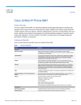
1
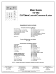
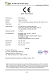
TABLE OF CONTENTS IMPORT SAFETY INSTRUSTIONS ............................................................ 2 READ THIS FIRST .............................................................................. 2 1. INTRODUCTION ...................................................................................... 5 1.1 General ................................................................................5 2. SAFTETY OF INSTALLATION .....................................................7 2.1 Planning the installation .........................................................7 2.2 Servicing instructions .............................................................8 2.3 Installation and Operation ..................................................8 2.4 Technical Specification ........................................................11 2.5 LED Information .................................................................12 3. WARRANTY-LIABILITY ..............................................................13 4. COMPATIBLLITY AND CAPACITY ............................................14 5. INSTALLATION PROCEDURE ...................................................14 5.1 Parts and Tools ............................................................................ 15 5.2 Installation of micro inverter on the back of the solar panel ...... 16 MIG240UL00 – Micro Inverter 5.3. Installation of micro inverter on the solar panel rack….22 5.4. Installation Map…………………………………………28 USER MANUAL 5.5. Sample wiring diagram, 240Vac single phase…………..29 1 -0- IMPORT SAFETY INSTRUSTIONS READ THIS FIRST Warning SAVE THESE INSTRUCTIONS: This manual contains important instructions for Darfon MIG240UL00 that shall be Risk of Electric Shock, Do Not Remove Cover. No User Serviceable Parts Inside. Refer Servicing To Qualified Service Personnel. followed during installation and maintenance of the micro inverter. Before using this unit please read these operating instructions an authorized service personnel Both ac and dc voltage sources are terminated inside this carefully. Take special care to follow the warnings indicated in equipment. Each circuit must be individually disconnected the unit itself as well as the safety suggestion listed below. before servicing and Safety Symbols To reduce the risk of injury and to ensure the continued safe Repairs and internal servicing should only performed by when the photovoltaic array is exposed to light, it supplies a DC voltage to this equipment. Hot Surfaces-To reduce the risk of burns-Do not touch. Enclosure Rating: type 6 (raintight) operation of this product, the following safety instructions and warnings are marked in this manual. ! ! Warning, risk of electric shock The lighting flash with arrowhead symbol, within an equilateral triangle, is intended to alert the user of the presence of dangerous voltage within the product’s enclosure that may be constitute a risk of injury or death to users and/or installers. Caution (refer to accompanying documents) The exclamation point within an equilateral triangle is intended to alert the user of the presence of important information to prevent damage to this product. 2 Caution Perform all electrical installations in accordance with all applicable local electrical codes and the National Electrical Code (NEC), ANSI/NFPA 70. The MIG240UL00 micro inverters may contain high voltages and the risk of electrical shock, even when no external voltage is present. Only the trained qualified electrical personnel are allowed to perform the electrical installation, wiring, opening, repair, and modification of the MIG240UL00 inverters. MIG240UL00 micro inverters are designed to operate at 3 full power at ambient temperatures as high as 65°C (150° F). The micro inverter housing is designed for outdoor installation and complies with the NEMA 6 environmental enclosure rating standard. The temperature of the heat sinks outside of the device can reach over 85°C in normal operation. To reduce risk of burns, use caution when working with micro inverters. Both AC and DC voltage sources are terminated inside this equipment. Each circuit must be individually disconnected before servicing and when the photovoltaic array is exposed to light, it supplies a DC. Failure to comply with these precautions or with specific warnings elsewhere in this manual violates safety standards of design, manufacture, and intended use of the device. The manufacturer assumes no liability for the customer’s failure to comply with these requirements. Electrical installation must be carried out correctly to meet the applicable regulations and standards. MIG240UL00 inverters shall be able to be enduringly installed. MIG240UL00 inverters shall be installed as per the instructions stated in this manual. Connect the MIG240UL00 inverter to the grid only after receiving prior approval from the electrical utility company. Warning :This unit is not provided with a GFDI device and intended to be installed under the Solar Module therefore please don’t install this unit where it is expected to be contacted by any person 1 INTRODUCTION 1.1 General Thank you for choosing DARFON’s MIG240UL00 Micro Inverters as your power conversion device for your solar power system. DARFON’s MIG240UL00 micro inverter is a compact unit, which is installed at the back of each solar module to convert DC power generated by solar module to AC power for powering your house appliances and connecting to the electricity grid without the need for a string or central inverter. The AC output from MIG240UL00 micro inverter is synchronized and in-phase with the electricity grid. DARFON’s micro inverter solution has a number of distinct advantages: Optimal energy harvest – it maximizes the power harvested from each solar module and therefore the entire PV array. This is accomplished by performing Maximum Power Point Tracking (MPPT), an electronic technique for maximizing the power harvested from each module under varying environmental conditions, and performance monitoring for each individual solar module. Performing MPPT on each solar module ensures maximum harvest of energy even under partially shaded conditions. Degradation in the performance of any one module, due to module mismatch, shadows from trees or chimneys, or obstructions from leaves or debris, does not degrade the performance of other modules and therefore has minimal impact on the power harvested from the PV array. This typically results in improved power harvest of up to 20% from the solar PV system and represents a significant cost/performance advantage. 4 5 Improved safety – as power conversion from DC to AC is done at The advantages of DARFON’s Micro Inverter: MIG240UL00 is each solar module, high voltage DC wiring is eliminated, making primarily reflected in its high efficiency and long life. Careful the solar system intrinsically safer, and specialized DC practices or equipment are not required for installation. optimization of the overall inverter system’s cost and efficiency lead to the choice of a micro inverter for use with one arrays per Increased lifetime and reliability – it eliminates the single most inverter. common cause of failure in solar PV systems, the string or central inverter, which typically requires replacement at least once over the life of the solar modules, adding significant cost. DARFON’s solar micro inverters have been designed for high reliability operations, to operate in real world conditions from -40 degrees C to +65 degrees C without degradation of performance, and achieve a peak efficiency of 94.1% over the temperature range. Enhanced monitoring capability – performance monitoring of the PV array is highly enhanced as each module’s performance can be provides users and installers with real-time detailed information to This micro inverter uses Darfon’s proprietary maximum power point (MPPT) tracking technology to get the maximum amount ensure that the solar system performance is optimized over the life of energy form the solar array, which helps your arrays to have of the installation. The information can be used to promptly detect maximum output at all times. viewed, a capability not available with string inverters. This uniquely performance issues and pinpoint the exact location and nature of the problem, which provides precise guidance for required 2 SAFETY OF INSTALLATION maintenance, a capability not possible with string inverter systems. Simplified PV array design and installation – for rooftop installations, solar modules can be installed on any available space resulting in ease of design of the PV array compared with conventional inverter installations where design of the PV array module placement is complicated by shading issues. This makes solar installations easier, faster and cheaper to implement. Also, installers do not need to match the performance levels of adjacent solar modules in order to optimize the performance of the PV array. 2.1 Planning the installation For the safety of installation, personnel must remove all conductive jewelry or equipment during the installation or service of the device parts, connector and/or wiring. The permanently wired equipment must be installed by licensed electrician. Please follow all the instructions carefully and adhere to all the information on cautions or warnings. 6 7 2.2 Servicing instructions Only the trained qualified personnel are required to mount, operate, correct or repair this device. This list does not contain all measure pertinent to the safe be provided to ensure operational safety. Read all instructions and cautionary marks in the manual Correct AC/DC grounding and short circuit protection must carefully before start the installation. operation of the device. If any special problems arise which are not recorded in this manual, please contact our Switch off the circuit breakers before installation and wirings. authorized dealer/service partner/ DARFON customer care for the information. Connect the micro inverter to the utility grid only after receiving prior approval from the electrical utility company. 2.3 Installation and Operation Installation of the device must be in accordance with the safety regulations and all other relevant national or local regulations. Do not stand on a wet location while doing installation and wirings.Enclose the outer covering well before switch on the circuit breakers. The AC and DC connectors are tool-removable only , please ensure the micro inverter is not disconnected from Connect the male end of the micro inverter DC connector cable to the female end of the PV module connector cable. Connect the female end of the micro inverter DC connector the PV modules under load and switch off the circuit breakers. cable to the male end of the PV module. : Grounding symbol Wieland ALTW Disconnecting AC connector Disconnecting DC connector 8 9 APP Allowed changes in your electrical system to be carried out 2.4 Technical Specification only by qualified electricians. ! Caution Lightning surge suppression- Lightning does not actually Input Data (DC) Recommended input power (STC) Maximum input DC voltage 240W 60V need to strike the equipment or building where the PV system is installed to cause damage. Often, a strike nearby will induce voltage spikes in the electrical grid that can damage equipment. Darfon ’ s Micro inverters Maximum Peak power tracking voltage 24 ~ 40V Min start voltage 24V (MIG240UL00) have integral surge protection, much higher Max. DC short circuit current 12A than most traditional inverters. However, if the surge has sufficient energy, the built- in protection in the device would Max. input current 10A Output Data (AC) exceed, and the device can be damaged. As the Darfon Limited Warranty does not cover “extraordinary and unexpected manifestation of the forces Maximum output power 220W of nature, ” Nominal output current 0.917A Nominal voltage/range 211 / 240 / 264 V Nominal frequency/range 59.3 / 60 / 60.5 Hz such as lightning strikes, therefore it is recommended to install surge protection as part of any solar installation. We recommend the following protection devices. These have been tested to ensure that they do not interfere with power line communications. Install per vendor instructions. Power factor >0.95 Efficiency Residential: Vendor: Citel, Part Number DS72RS-120 Application: Residential 120/240V Split Phase where N-G bond exists. Commercial: Vendor : Citel, Part Number SP-120 Application: Branch panel protection See the vendor datasheet for DS70R, (which includes the DS72RS120) or for SP-120 at http://www.citelprotection.com/english/citel_data_sheets/ac_protection Peak inverter efficiency 94.10% CEC weighted efficiency 93% Nominal MPP tracking 99% Mechanical Data Operating temperature range -40ºC to +65ºC / 10 11 Night time power consumption 3 51mW 200mm x 130mm x 37mm Dimensions (WxHxD) Features WARRANTY-LIABILITY If a fault or defect is present on receipt of the unit which is within DARFON’s scope of responsibility, DARFON shall have the right to either repair the fault or supply a replacement unit. Replaced parts shall be the property of Communication Powerline Compliance EN 61000-6-2, EN 61000-6-3,FCC Part15 Class B, DARFON. Should the fault repairs or replacement delivery UL 1741, IEEE 1547 not be successful, the statutory provisions shall be valid. The period of warranty shall be 25 years, beginning on the date of purchase. Please retain your receipt as proof of purchase. Should your micro inverter require servicing, please contact your dealer or DARFON Customer Service. 2.5 LED Information Orange Green Red Initialization flash off off Meet input start voltage on off off MPPT/Grid mode off on off Warning message, derating Off flash off Halt manually/Calibration Off off flash(2Hz) fault with restart Off off flash(0.5Hz) Fault without restart Off off on Flash programming Off off flash(2Hz) No responsibility shall be accepted for damage caused through any of the following reasons: Unsuitable or improper storage or use, incorrect installation or commissioning by the owner or third parties, changes or modifications, incorrect or negligent handling, overuse, chemical, electrochemical or electrical interference, unless this is attributable to negligence on the part of DARFON ELECTRONICS CORP., If provides and individual warranty, this means that the unit supplied will be free of faults for the length of the warranty period. 12 DARFON 13 (2) Type mounted on the PV racking 4 COMPATIBLLITY AND CAPACITY Electrical Compatibility Model Number PV MPPT Voltage Range PV Module Connector Type MC-4 Locking, MIG240UL00 24V~40V Tyco Solarlock Locking, or Amphenol H4 Locking DC Voltage and Capacity Maximum number of MIG240s per AC Branch Circuit Overcurrent Protection 240V with 10AWG AC Trunk Cable 25 30Amp Breaker 240V with 12AWG AC Trunk Cable 17 20Amp Breaker 5.1 Parts and Tools NOTE: 1. DO NOT exceed the maximum number of micro inverters in an AC This section provides a list of products, parts, and tools needed branch circuit as listed in the table above. 2. Each AC branch circuit must be protected by a dedicated circuit breaker for installing and setting up the PV system. Products: of 30A or less if using 10 AWG trunk cable, or 20A or less if using 12 AWG • MIG240UL00 micro inverter trunk cable. • PV module • PV racking (with a DC junction box attached to one of its ends) 5 INSTALLATION PROCEDURE Outline drawing – MIG240UL00 micro inverter Parts: (1) Type mounted on the back of the PV panel • Cables and related parts: - DC and AC cables (with DC connectors and AC T-branch connectors) - Cable clips - Sealing caps (for any unused drops on the AC Cable) - Terminators (one needed at the end of each AC branch circuit) • AC junction boxes • Gland or strain relief fitting (one per AC junction box) 14 15 Tools: 1. Original PV Panel • Torque wrench, sockets, wrenches for mounting hardware • Adjustable wrench or open-ended wrench (for terminators) The micro inverter can be mounted and installed on the back of the PV module panel (screw-tightened to the frame of the panel) or on the standard PV racking, depending on the plan for layout of your PV system. 5.2 Installation of micro inverter on the back of the solar panel: Outline drawing - Solar panel (PV module) and micro inverter 2. Add holding-device and snap it to the panel frame. 16 17 3. Drill screw holes (M5.5). 5. Install accessory (M4 support bolts x 3). First peel off glues on the back. 4. Drilling completed. 6. Support bolts installed. 18 19 7. Mount the micro inverter and line up the screw holes Photo of Actual Finish on the inverter with the three M4 bolts. Spin the three M4 nuts on the bolts and tighten them with a wrench. 8. Mounting and Installation completed. 20 21 5.3. Installation of micro inverter on the solar panel rack (PV module racking): Outline drawing - micro inverter 1. Lay out the trunk cable at the location required. With the trunk connectors aligning with the position where the micro inverter needs to be installed, secure the cable on either side of rack using tie wraps or clips. 2. MIG240UL00 requires a separate equipment grounding conductor such as Wiley “WEEB” grounding washers or other similar parts which can provide with an equipment grounding conductor in AC cabling systems. Align MIG240UL00 holes with the holes on the rack and tighten the screws properly. 22 3. MIG240UL00 has a clip to hold the Grounding electrode conductor. After spreading the grounding, secure it with the clip supplied. 23 a. Indicate the approximate center of each PV module on the PV rack. Evaluate against potential collection of moisture or water for the most suitable angle to mount the inverter. 4. Connect the micro inverter with the trunk cable. b. Evaluate the location of the micro inverter with respect to the DC junction box. Ensure that the inverter does not obstruct the PV module frame or stiffen braces and that the connector from one micro inverter can easily reach that of other Inverters. 24 25 5. Install the AC Branch Circuit Junction Box a. Measure service entrance conductors to confirm AC service at the site. Acceptable ranges are shown in the table below: 240 Volt AC Single Phase L1 to L2 211 to 264 Vac L1, L2 to neutral 106 to 132 Vac b. Mount an adapter plate at a suitable location on the PV racking system (typically at the end of a row of modules). The adapter plate must be installed with an appropriate junction box. c. Connect the open wire end of the AC interconnect cable into the junction box using an appropriate gland or strain relief fitting. The AC interconnect cable requires a strain relief connector with an opening of 3/8 inches in diameter. 26 27 Darfon Micro Inverter Installation Map Sample Wiring Diagram - 240 Vac, single phase with monitoring system 28 29 Manufactured by: DARFON ELECTRONICS CORP. 167 Shan-ying Road, Gueishan, Taoyuan 333, Taiwan, (R.O.C.) Tel: +886 3 2508800 www.DARFON.com US Office: Darfon America Corp. 3031 Tisch Way, STE 610 San Jose, CA 95128 Tel: +1 408 260 3880 30