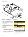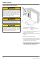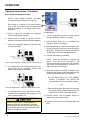
1
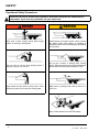
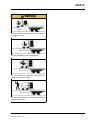
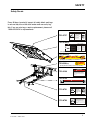
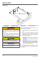
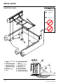
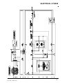
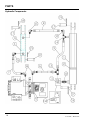
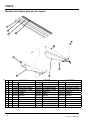
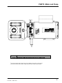
HP-H SERIES Dock Leveler Owner’s/User’s Manual McGuire • Division of Systems, Inc. • W194 N11481 McCormick Drive • Germantown, WI 53022 800.624 8473 • fax: 262.257.7399 • www.wbmcguire.com • [email protected] Printed in U.S.A. Copyright © 2010 Manual No. 4111-0018 October 2011 March 2012 Table of Contents Safety Page Recognize Safety Information........................................................................... General Operational Safety Precautions......................................................... Operational Safety Precautions........................................................................ Maintenance Safety Precautions...................................................................... Safety Decals...................................................................................................... Owner’s/User’s Responsibilities....................................................................... Introduction General Information........................................................................................... Dock Leveler Stock Specifications................................................................... Component Identification.................................................................................. Theory................................................................................................................. 1 1 2 4 5 6 8 8 9 9 Installation Prepare Pit.......................................................................................................... 10 Prepare Dock Leveler....................................................................................... 11 Install Dock Leveler.......................................................................................... 12 Install Control Panel and Wiring...................................................................... 18 Put New Leveler Into Service........................................................................... 19 Operation Operating Instructions...................................................................................... 20 Ramp Loading/Unloading Instructions........................................................... 21 End Loading/Unloading Instructions.............................................................. 22 Maintenance Service Dock Leveler Safely............................................................................ 23 Periodic Maintenance....................................................................................... 24 Adjustments Hydraulic Pump Schematic.............................................................................. 26 Adjust Main System Pressure.......................................................................... 27 Adjust Auto Return To Dock (ARTD) Below Dock Control........................... 28 Adjust Down Speed and Lip Extension.......................................................... 30 Electrical Single Phase (Nema 4)...................................................................................... 32 Three Phase (Nema 4)....................................................................................... 33 Single Phase (Nema 12).................................................................................... 34 Three Phase (Nema 12)..................................................................................... 36 Control Panel Pictures...................................................................................... 36 Single Phase Control Panel Parts (Nema 12)................................................. 40 Three Phase Control Panel Parts (Nema 12).................................................. 42 Troubleshooting Troubleshooting................................................................................................ 44 Parts Frame and Platform........................................................................................... 48 Hydraulic Components..................................................................................... 52 Weather Seal, Rubber Style and Brush Style................................................. 54 Full Range Toeguards....................................................................................... 54 Power Pack Assembly ..................................................................................... 55 Miscellaneous Notes................................................................................................................... 54 Customer Information....................................................................................... 57 Warranty .......................................................................................... Back Cover SAFETY Recognize Safety Information Safety-Alert Symbol The Safety-Alert Symbol identifies important safety messages on equipment, safety signs, in manuals, or elsewhere. When you see this symbol, be alert to the possibility of personal injury or death. Follow the instructions in the safety message. General Operational Safety Precautions Read and understand the operating instructions and become thoroughly familiar with the equipment and its controls before operating the dock leveler. Never operate a dock leveler while a safety device or guard is removed or disconnected. The use of the word DANGER signifies the presence of an extreme hazard or unsafe practice which will most likely result in severe injury or death. The use of the word WARNING signifies the presence of a serious hazard or unsafe practice which may result in serious injury or death. The use of the word CAUTION signifies possible hazard or unsafe practice which could result in personal injury. IMPORTANT The use of the word IMPORTANT is to draw attention to a procedure that needs to be followed to prevent machine damage. Never remove DANGER, WARNING, or CAUTION signs or decals on the equipment unless replacing them. on Z ng ati e r e Op era Op g tin ne Zo Do not start the equipment until all unauthorized personnel in the area have been warned and have moved outside the operating zone. Remove any tools or foreign objects from the operating zone before starting. Keep the operating zone free of obstacles that could cause a person to trip or fall. 4111-0018 — March 2012 1 SAFETY Operational Safety Precautions Learn the safe way to operate this equipment. Read and understand the manufacturer’s instructions. If you have any questions, ask your supervisor. Stay clear of dock leveling device when freight carrier is entering or leaving area. Chock/restrain all freight carriers. Never remove the wheel chocks until loading or unloading is finished and truck driver has been given permission to drive away. Do not move or use the dock leveling device if anyone is under or in front of it. Do not use a broken or damage dock leveling device. Make sure proper service and maintenance procedures have been performed before using. Keep hands and feet clear of pinch points. Avoid putting any part of your body near moving parts. Make sure lip overlaps onto trailer at least 4 in. (102 mm). Keep a safe distance from both side edges. 2 4111-0018 — March 2012 SAFETY Do not use dock leveling device if freight carrier is too high or too low. Do not overload the dock leveling device. Do not operate any equipment while under the influence of alcohol or drugs. Do not leave equipment or material unattended on dock leveling device. 4111-0018 — March 2012 3 SAFETY Maintenance Safety Precautions ALWAYS disconnect electrical power source and ground wire before welding on dock leveler. DO NOT ground welding equipment to any hydraulic or electrical components of the dock leveler. Always ground to the dock leveler frame. Failure to follow these instructions may result in damage to dock leveler and/or serious personal injury or death. Hydraulic and electrical power must be OFF when servicing the equipment. For maximum protection, use an OSHA approved locking device to lock out all power sources. Only the person servicing the equipment should have the key to unlock the device. DO NOT grind or weld if hydraulic fluid or other flammable liquid is present on the surface to be ground or welded DO NOT grind or weld if uncontained hydraulic fluid or other flammable liquid is present. Stray sparks can ignite spills or leaks near the work area. Always clean up the oil leaks and spills before proceeding with grinding or welding. Always keep a fire extinguisher of the proper type nearby when grinding or welding. Always post safety warnings and barricade the work area at dock level and ground level to prevent unauthorized use of the unit before maintenance is complete. Failure to follow these instructions may result in serious personal injury or death. ALWAYS stand clear of dock leveler lip when working in front of the dock leveler. Failure to do this may result in serious personal injury or death. The maintenance prop must be in the upright “service” position when working under the dock leveler. For maximum protection, use an OSHA approved locking device to lock the maintenance prop in the service position. Only the person servicing the equipment should have the key to unlock the device. 4 4111-0018 — March 2012 SAFETY Safety Decals Every 90 days (quarterly) inspect all safety labels and tags to ensure they are on the dock leveler and are easily legible. If any are missing or require replacement, please call 1-800-643-5424 for replacements. 5.06" DANGER 2.40" 1751-0727 CRUSH HAZARD Maintenance prop must support leveler behind bar. Do not force maintenance prop forward of bar to support lip. Refer to owner’s/user’s manual for proper use. Failure to comply will result in death or serious injury. 1751-0730 (x2) 1751-0727 Control Box Size: Decal Size: 9.12" 5.06 x 2.40 File Name: 1751-0727 SAFETY INFORMATION DANGER 3.25" Unsupported dock leveler ramps can lower unexpectedly. Before allowing vehicle to leave the dock always: Ensure that no equipment, material or people are on the dock leveler. Return the dock leveler to its stored position at dock level. Operation 1. Read and follow all instructions and warnings in the owner’s/user’s manual. 2. Use of dock leveler restricted to trained operators 3. Always chock trailer wheels or engage truck restraint before operating dock leveler or beginning to load or unload. 4. Never use hands or equipment to move the ramp or lip 5. Before activating dock leveler: Ensure trailer is backed in against bumpers. Remove any end loads if required. Check trailer alignment to avoid lip interference. If lip does not lower to trailer bed, reposition vehicle. 6. Ensure that truck bed supports extended lip or the leveler frame Failure to follow posted instructions will result in death or serious injury. supports the ramp before driving on ramp. 7. Stay clear of hinges and front and sides of moving dock leveler. 8. Never use damaged or malfunctioning dock leveler. Report problems immediately to supervisor. Maintenance/Service 1. Read and follow all instructions, warnings and maintenance schedules in the owner’s/user’s manual. 2. Maintenance/Service of dock leveler restricted to trained personnel. 3. Place barriers on the driveway and on dock floor to indicate service work is being performed. 4. DO NOT ENTER PIT unless dock leveler is securely supported by maintenance prop. 5. If electrically powered turn off and use OSHA lockout/tagout procedures. Call 262.255.1510 for replacement placards, warning labels, or owner’s/user’s manuals. (decal placed in same position on both sides) Control Box Size: Decal Size: 9.12 x 3.25 File Name: 1751-0730 1751-0329 (x2) DO NOT FORK THIS SIDE (decal placed in same position on both sides) Control Box Size: Decal Size: 13 x 2 File Name: 1751-0329 FORK HERE 1751-0330 (x2) (decal placed in same position on both sides) Control Box Size: Decal Size: 6 x 2 File Name: 1751-0330 REV A ! DANGER 1751-0138 CRUSH HAZARD DO NOT REMOVE hydraulic cylinder until leveler is safely supported by maintenance prop. Refer to owner’s/user’s manual for proper maintenance procedure. Failure to comply will result in death or serious injury. P O W E R A M P M C G U I R E D L M Size: 8.72" Control Size: Box Decal 4 x2 1.02" 1751-0729 L o a d i n g D o c k E q uFilei Name: p m1751-0138 e n Rev t A DOCK LEVELER SAFETY DANGER LABEL LOCATIONS CRUSH HAZARD Do not work under dock leveler unless this maintenance prop has been secured in the MATERIAL upright position. See owner’s/user’s manual for proper procedures. Failure to comply 1751-0729 will result in death or serious injury. DRAWN BY BKM TOLERANCES (UNLESS OTHERWISE NOTED) DATE CHECKED BY 10/17/2008 DRAWING NO. FRACTIONAL: 1/32" DECIMAL: Control Box Size: .00 = .01" Decal Size: 8.72 x 1.02 File Name: 1751-0729 Rev A .000 = .005" CRUSH HAZARD 5.05" Rotate prop to maintenance 2.40" ANGULAR: 1 1751-0731 DL SAFETY DANGER LABELS position. Open the pin latch Inc. retains any and all This print is the property of Systems, Inc. and represents a proprietary article in which Systems, patent and other rights, including exclusive rights of use and/or manufacture and/or sale. and insert through the Possession of this print does not convey any permission to reproduce, print or manufacture the article or articles therein, such permission to be maintenance propshown housing. granted only by written authorization signed by an officer or other authorized agent of Systems, Inc. thereof. Close the pin latch to secure prop. Use every time dock leveler is serviced. Failure to comply will result in death or serious injury. 1751-0731 Control Box Size: Decal Size: 5.05 x 2.40 5.92" File Name: 1751-0731Rev A 1751-0726 2.36" DANGER CRUSH HAZARD DO NOT ENTER PIT unless dock leveler is safely supported by maintenance prop. Place barriers on driveway and dock floor to indicate service work being performed. Refer to owner’s/user’s manual for proper maintenance procedures. Failure to comply will result in death or serious injury. 1751-0726 Control Box Size: Decal Size: 5.92 x 2.36 File Name: 1751-0726 4111-0018 — March 2012 5 OWNER’S/USER’S RESPONSIBILITIES 1. The owner/ user should recognize the inherent dangers of the interface between the loading dock and the transportation vehicle. The owner/ user should, therefore, train and instruct all operators in the safe operation and use of the loading dock equipment in accordance with manufacturer’s recommendations and industry standards. Effective operator training should also focus on the owner’s/user’s company policies and operating conditions. Maintaining, updating and re training all operators on safe working habits and operation of the equipment, regardless of previous experience, should be done on a regular basis and should include an understanding and familiarity with all functions of the equipment. Owner’s/user’s shall actively maintain, update and retrain all operators on safe working habits and operations of the equipment. 2. The manufacturer shall provide to the initial purchaser all necessary information regarding Safety Information, Operation, Installation and Safety Precautions, Recommended Initial and Periodic Inspections Procedures, Planned Maintenance Schedule, Product Specifications, Troubleshooting Guide, Parts Break Down, Warranty Information, and Manufacturers Contact Information, as well as tables to identify the grade(slope) for all variations of length or configuration of the dock leveling device and information identifying the maximum uncontrolled drop encountered when sudden removal of support while in the working range of the equipment. 3. It is recommended that when the transportation vehicle is positioned correctly in the dock opening and in contact with both bumpers, there shall be a minimum of 4.00 inches (100mm) overlap of the leveling device and the transportation vehicle at all times during the loading and unloading process. 4. The Owner/User must review all name plates, placards, decals, instructions and posted warnings and place the same in view of the operator or maintenance personnel for whom such warnings are intended for. Contact manufacturer for any replacements. 5. Manufacturer’s recommended periodic maintenance and inspection procedures in effect at the date of shipment shall be followed at all times. Written documentation of maintenance, replacement parts or damage should be retained. In the event of damage notification to the manufacturer is required. 6. Loading dock equipment that has been structurally damaged or has experienced a sudden loss of main support while under load (such as what might occur when a transport vehicle pulls out from under the leveling device) shall be removed from service, inspected by a manufacturer’s authorized representative, and repaired or replaced as needed before being placed back in service. 7. Any modifications or alterations of loading dock equipment shall only be done with prior written approval from the manufacturer and the same shall be at least as safe as the original equipment was prior to the modification and shall also satisfy all safety requirements of the manufacturer for the particular application of the leveling device. 8. When industrial moving devices are being used in the loading or unloading of product from the transportation vehicle, this vehicle shall have the brakes and wheel chocks applied appropriately or all other positive restraining device shall be fully utilized. It is recommended that trailers with air-ride suspension systems shall have its air exhausted prior to performing loading and unloading operation to minimize trailer bed drop. 9. Loading dock safety equipment should never be used outside of its intended use, vertical working range, or capacity. Please consult the manufacturer if you have any questions as to the use, vertical working range or capacity of the equipment. Only properly trained and authorized personnel should operate the equipment. 10.When selecting loading dock safety equipment, it is important to consider not only present requirements but also future plans and any possible adverse conditions, environmental factors or usage. 6 4111-0018 — March 2012 NOTES This page intentionally left blank 4111-0018 — March 2012 7 INTRODUCTION General Information Dock Leveler Stock Specifications HP/H dock levelers are available in the following sizes, weight capacities, and options: Width: HP/H 6 ft (1828.8 mm) 6-1/2 ft (1981.2 mm) 7 ft (2133.6 mm) Length 6 ft (1828.8 mm) 8 ft (2438 mm) 10 ft (3048 mm) 12 ft (3658 mm) Congratulations on your choice of a McGuire dock leveler. This manual covers the HP/H series hydraulic dock leveler. Designed by McGuire. to be a marvel of simplicity and efficiency, your dock leveler, when properly installed, will provide many years of trouble-free performance with an absolute minimum of maintenance. Its revolutionary hydraulic system efficiently controls and operates every function. To obtain maximum performance and longest possible use, a simple program of preventive maintenance is recommended. Capacity (CIR*) 25,000 lb (11 340 kg) 30,000 lb (13 608 kg) 35,000 lb (15 876 kg) 40,000 lb (18 144 kg) 45,000 lb (20 412 kg) 55,000 lb (24 948 kg) 75,000 lb (34 019 kg) 100,000 lb (45 359 kg) * CIR (Comparative Industry Rating) Call McGuire, to discuss available voltages, phases and options to meet your specific needs. The HP/H series dock leveler comes equipped with an electrical control panel, which allows pushbutton operation of the dock leveler functions. Each HP/H dock leveler unit and control panel has been factory prewired and tested to ensure satisfactory operation. To illustrate which connections are to be made in the field at installation, electrical drawings are included with each order or by contacting McGuire Technical Services. Once again, thank you and congratulations on your purchase of a McGuire hydraulic dock leveler. 8 4111-0018 — March 2012 INTRODUCTION Component Identification C A B G F E D J I H E A — Lip B — Platform C — Lip Cylinder D — Powerpack (Motor/Pump/Reservoir) E — Prop Pin and Clip F — Platform Cylinder G — Main Frame H — Lip Keepers (2 used) I — Maintenance Prop J —Toe Guard (2 used) THEORY The HP/H dock leveler uses hydraulics and one‑button operation for ease of use. Platform (B) is raised by pushing and holding the RAISE button (K). This activates an electric motor (D) which, in turn, drives a hydraulic pump. The hydraulic pump forces oil into the platform cylinder(s) (F), causing the platform to rise. Releasing the RAISE button allows the platform to lower. 4111-0018 — March 2012 K 9 INSTALLATION Prepare Pit A 14” C B 10” D A—Distance (Pit Width) (Front and Rear) B— Distance (Dock Floor-to-Pit Floor) (All Four Corners) Post safety warnings and barricade the work area at dock level and ground level to prevent unauthorized use of the dock leveler before installation has been completed. Failure to follow the installation instructions can result in damage to dock leveler, the facilities, and/ or serious personal injury or death. Only trained installation professionals with the proper equipment should install this product. IMPORTANT DO NOT remove the shipping bands around the dock leveler lip until instructed to do so. 10 C— Distance (Pit Length) (Both Sides of Pit) D— Distance (Pit Corner‑to‑Corner) (Top, Bottom, and Both Sides) Before lowering the dock leveler into the pit, the following must be performed: 1. Remove all debris from the pit and sweep the pit clean. 2. Check the entire dock leveler pit for proper construction according to approved/certified pit drawings. Make sure pit is square by making the following measurements: • Measure pit width distance (A) at both front and rear of pit. • Measure dock floor-to-pit floor distance (B) at all four corners. • Measure pit length distance (C) at both sides. • Measure corner-to-corner (crisscross) distance (D) at both sides. Take measurements at dock floor level and at pit floor level. If any measurement is off by more than 1/8 in. (3.18 mm), contact Systems, Inc. Technical Services before proceeding. 4111-0018 — March 2012 INSTALLATION Prepare Dock Leveler IMPORTANT A DO NOT remove the shipping bands (B) around the platform lip and leveler frame at this time. The shipping bands are needed to hold the leveler together during the installation process. Turn to page 15 for front pick up. 1. Remove any control panel and bumpers that may be banded to the frame of the dock leveler. DO NOT remove the shipping bands (B) around the platform lip and leveler frame at this time IMPORTANT B A— Lifting Bracket (2 used) B — Shipping Bands McGuire dock levelers are designed with installation in mind. Each unit is shipped with lifting brackets (A) fastened to the platform side joists. A third sling may be used to install the unit. The dock leveler is heavy. Use a lifting device and chains with the appropriate lifting capacity and reach. Always use the lifting brackets provided with the unit whenever lowering or lifting a dock leveler into or out of a pit. Failure to follow these instructions may result in damage to dock leveler and/or serious personal injury or death. 4111-0018 — March 2012 DO NOT overtighten the lifting bracket hardware. Overtightening can damage the weather seal, if equipped. NOTE:Overall width of platform and lifting brackets (A) must be kept to a minimum to prevent interference between the lifting brackets and the pit walls as the dock leveler is lowered into the pit. 2. Make sure the mounting hardware of lifting brackets (A) is snug. The brackets should pivot relatively freely on the mounting cap screw. DO NOT overtighten. 3. Attach lifting chains to lifting brackets (A) and to a lifting device (i.e., hoist or fork truck) having the appropriate lifting capacity and reach. 4. Remove shipping pallet, if present, before putting the dock leveler into the pit. 11 INSTALLATION Install Dock Leveler Shim Stacking Methods M N P Q A— Distance (Leveler Frame Height) B— Shim Locations (Under Rear Vertical Supports) C— Shim Location (Under Maintenance Prop,Lip keepers, Main cylinder) D— Dock Floor E—Rear Pit Curb Angle F— String 12 G— Rear Hinge Frame Angle H— Distance (Dock Floor-toPit Floor) J— Distance (Top of Shim Stack-to-Dock Floor) K— Shim Stack L— Dock Leveler Frame M — Pyramid (Preferred) N— Stepped (Acceptable) P— Offset (Not Acceptable) Q — Straight (Not Acceptable) 4111-0018 — March 2012 INSTALLATION NOTE:McGuire dock levelers are designed with a nominal 1/2 in. (12.7 mm) shimming distance to allow for pit inconsistencies. 1. Determine height of shim stack (K) for each shim location (B) by performing the following: a. Measure leveler frame height distance (A). b. Measure dock floor-to-pit floor distance (H) at each shim location (B). Write down the dimensions obtained at each location. c. Subtract distance (A) from distance (H) to obtain the shim height. Repeat for each shim location. 4. For all HP/H models, put a minimum 1/4 in. (6.6 mm) thick shim at locations (B and C). NOTE: A 1/4 in. (6.6 mm) thick shim at locations (B and C) is used only as a starting point. The final shim stack height will be determined after dock leveler is lowered into the pit. The dock leveler is heavy. Use chains and a lifting device with the appropriate lifting capacity and reach. Failure to do so may result in damage to dock leveler and/or serious personal injury or death. IMPORTANT The minimum size of the shim that contacts the leveler frame (i.e., the top shim of each shim stack) must be at least 4-1/2 x 4-1/2 in. (114.3 x 114.3 mm) to support the full width of the frame rail and to provide a shelf for a fillet weld. Use the thickest shim stock possible for stability and weld penetration purposes. DO NOT use multiple layers of 1/8 in. (3.18 mm) or thinner shim stock. 2. Using the results obtained in step 1, create the individual shim stacks on the pit floor at locations (B). Build each shim stack (K) using the pyramid method (M) (preferred) or stepped method (N) with the top shim having a minimum size of 4-1/2 x 4‑1/2 in. (114.3 x 114.3 mm) and each successive lower shim being larger so the shims can be welded together using a fillet weld. DO NOT use offset method (P) or straight method (Q). 5. Using an appropriate lifting device connected to the lifting brackets, lower dock leveler into the pit so rear hinge frame angle (G) is tight against rear pit curb angle (E) across full width of the leveler frame. 6. Allow rear of dock leveler to rest on the rear shims while keeping the front of the dock leveler level with the dock floor. 7. For all HP/H models, add shims at front shim locations (C) so front of dock leveler will stay level with dock floor when leveler is resting fully on shims. NOTE: To assist in obtaining an accurate measurement of distance (J), use a string (F) pulled tight across the pit opening, directly over the shim locations. 3. Verify that each shim stack is at the correct height by measuring distance (J) [top of shim stack (K) to dock floor]. Distance (J) must equal the dock leveler height (A). 4111-0018 — March 2012 13 INSTALLATION A— Front of Dock Pit B— Dock Leveler Frame C— Side Pit Curb Angle D— Gap [3/4 in. (19 mm) Minimum] 8. With rear hinge frame angle (F) tight against rear pit curb angle (G), perform/check the following: • Pry between the platform and rear hinge frame angle at locations (E) to make sure rear edge of platform is parallel to the rear hinge frame angle (F). • Gap (D) must exist equally along both sides of leveler so weather seal (if equipped) will not bind during dock leveler operation. 14 E— Pry Locations F— Rear Hinge Frame Angle G— Rear Pit Curb Angle H— Flare Bevel Weld, Typical (To Fit Spacing) 9. If gap (D) cannot be obtained equally at both sides of leveler, grind or add material at the rear edge of rear hinge frame angle (F) as needed. 10. Allow the dock leveler to rest fully on the shim stacks. Check that a smooth and level transition exists between the dock floor and the dock leveler platform. Add or remove shims as necessary until a smooth transition is obtained. 11. If leveler cannot be squared and/or made level as instructed in steps 8 — 10, contact Systems, Inc. Technical Services. 4111-0018 — March 2012 INSTALLATION IMPORTANT DO NOT grind or weld if hydraulic fluid or other flammable liquid is present on the surface to be ground or welded. DO NOT grind or weld if uncontained hydraulic fluid or other flammable liquid is present. Stray sparks can ignite spills or leaks near the work area. Always clean up the oil leaks and spills before proceeding with grinding or welding. Always keep a fire extinguisher of the proper type nearby when grinding or welding. Failure to follow these instructions may result in serious personal injury or death. IMPORTANT DO NOT connect the dock leveler electrical wiring and ground connections until all welding has been completed. DO NOT ground welding equipment to any hydraulic or electrical components of the dock leveler. Always ground welding equipment to the dock leveler frame, NEVER to the platform. Failure to follow these instructions may damage the motor, hoist cylinder, wiring, and/or control panel. NOTE:The illustration on the previous page shows a typical weld pattern. The weld pattern will vary slightly depending on size of dock leveler. 4111-0018 — March 2012 DO NOT weld continuously along the full length of the rear hinge frame angle. This can put unnecessary stress on the leveler components, causing the leveler to malfunction and shorten the lifespan of the affected components. 12. With the rear hinge frame angle (F) tight against the rear pit curb angle (G), weld the rear hinge frame angle (F) to the rear pit curb angle (G) using a 3/8 in. (9.5 mm) flare bevel skip weld — each weld being 6 in. (152 mm) long. Start at each end with a 6 in. (152 mm) long weld. Space all the other welds out evenly leaving approximately 6 in. (152 mm) space between each weld. 13. Weld front of dock leveler frame (B) to shims located under the keepers, then weld the shims to the front pit curb steel. 14. With leveler welded into place, remove the shipping bands from around lip and leveler frame. 15. If the platform is raised using an external lifting device or the hydraulic system is opened to atmosphere, air will enter into the hydraulic system. Whenever this happens, always cycle the leveler at least 4 times using the leveler’s own hydraulic power system before allowing the leveler to be put into service. This is to make sure all air is purged from the hydraulic cylinders. Failure to do this may result in serious personal injury or death. 15 INSTALLATION A— Platform Joists B—Platform Maintenace Prop 16. Using an external lifting device (i.e., crane or fork truck) attached to the platform lifting brackets, slowly raise the platform. Check for binding as platform is being raised. 17. If binding occurs, lower the platform. Reposition leveler and/or add or remove shims as necessary. Slowly raise platform again. If platform still binds, contact Systems, Inc. Technical Services for further instructions. 18. All HP/H models: a. Install shims under maintenance prop (B) where prop attaches to leveler frame. Make sure prop is solidly shimmed. b. Using the appropriate lifting device, attached to the platform lifting lugs, slowly raise the dock to the fully open position. C—Prop Pin and Clip Two people are required to engage the maintenance prop: one person to operate the lifting device, the other person to engage the maintenance prop. DO NOT use the maintenance prop to support the raised platform until the maintenance prop has been properly shimmed and welded. The shims must be welded to each other, the leveler frame, and to the front pit curb steel. Failure to do this may result in serious personal injury or death. c. Raise maintenance prop (B) to the service (upright) position and lock prop in this position using an OSHA approved locking device. (Supplied by others) d. Proceed to step 18. 16 4111-0018 — March 2012 INSTALLATION 19. All model levelers: Install shims at locations (B) (C) (Ref.page 12) using the pyramid or stepped shimming method. Both platform cylinder trunnions must be solidly shimmed the entire length of the trunnion. Make sure the trunnions are level from side-to-side as well as from front-to-back. 20. Finish weld all shims using a fillet weld. • Weld all shims within each shim stack to each other, then weld the shim stack to the leveler frame. • Weld the front leveler frame shim stacks to the front pit curb steel. Make sure the platform is properly supported in the raised position before entering the pit to finish weld the shims. Failure to do this may result in serious personal injury or death. 21. When all welding has been completed, paint all the welds and shims. NOTE: To pick up unit from the front, move forks closer together and slide over the frame and under the cross member. It may be necessary to unband the unit to gain access to the front, by lifting the lip up then sliding the forks under the cross member. (Ref: page 11) Shim Stacking Methods Front Pick Up M N P Q Rear Pick Up * For left/right orientation of dock leveler, see inside back cover of this manual. 4111-0018 — March 2012 17 INSTALLATION Install Control Panel and Wiring A The electrical power must be OFF prior to electrical installation. For maximum protection, use an OSHA approved locking device to lock out all power sources. Only the person installing the equipment should have the key to unlock the power source. Failure to follow these instructions may result in serious personal injury or death. B C DO NOT make any final electrical connections until all welding has been completed. Failure to do this may result in serious personal injury or death. All electrical work — including the installation of the disconnect panel, control panel, and final connections to the pit junction box — must be performed by a certified electrician and conform to all local and applicable national codes. A— Disconnect Panel (provided by others) B— Control Panel C— Distance, 48 in. (14 630 mm), minimum. 1. Mount the pushbutton control panel (B) so bottom of control panel-to-dock floor distance (C) is a minimum 48 in. (1219.2 mm). 2. Install electrical disconnect panel (A) if not already installed. 3. Install and connect the control wiring. 4. Connect the dock leveler power cable to the field wires in the pit junction box. Refer to the electrical drawings supplied with the dock leveler. 5. After all electrical connections in the pit have been made, disengage the maintenance prop and lower the platform using the external lifting device connected to the platform lifting brackets. 18 4111-0018 — March 2012 INSTALLATION Put New Dock Leveler Into Service 1. Disconnect the external lifting device and chains from the lifting brackets. 2. Check that the leveler is flush with the dock floor and that the platform lip contacts both lip keepers evenly. If an excessive transition exists between the dock floor and leveler and/or lip does not contact both lip keepers evenly, contact Systems, inc. Technical Services for further instructions. 3. Install the dock bumpers as required. 4. Turn the main electrical power ON. Always stand clear of platform lip when working in front of the dock leveler. Serious personal injury or death may result. 5. Raise the leveler platform fully by pushing and holding the RAISE button. NOTE: The platform of a properly operating dock leveler will automatically stop rising when it reaches its full raised height, at which point, the lip extends. (If the lip does not extend or extend fully, see Platform Rises to Full Height, But Lip Does Not Fully Extend in the Troubleshooting section.) 6. Release the RAISE button to lower the platform. As long as there is no truck present at the dock, the platform will lower to the full below-dock position with the lip extended. NOTE: If a truck is present, the platform will lower until the lip rests on the truck/trailer bed. (See Operating Instructions in Operation section.) 7. When the platform lowers to the full below-dock position, push and hold the RAISE button until the lip retracts and platform rises just enough to have the lip clear the lip keepers, then release the RAISE button to allow the platform to lower to the cross‑traffic (stored) position (lip engages lip keepers). NOTE: For dock levelers equipped with Auto Return To Dock (ARTD), the platform will automatically return to the cross-traffic position if the ARTD is in NORMAL mode. When the platform is about 1.00 inch from the full below-dock position, the platform will automatically rise to the cross-traffic position.(See below dock servicing and end loading for additional instructions) 8. Perform steps 5 – 7 at least four times to purge any air that may be in the hydraulic system and to ensure proper operation. Unless the dock leveler is equipped with a tethered remote, two people are required to engage the maintenance prop: one person to operate the unit, the other person to engage the maintenance prop. 9. Raise the platform fully. Hold the platform at this position using the RAISE button and move the maintenance prop to the service (upright) position. Release the RAISE button to allow the platform to lower until it is resting on the maintenance prop. 10. With the maintenance prop supporting the platform, remove the lifting brackets on both sides of the unit. 11. Push and hold the RAISE button until the maintenance prop drops to its stored position. Release the RAISE button and allow the platform to lower fully. 12. Perform step 7 if not equipped with ARTD. 4111-0018 — March 2012 19 OPERATION Operating Instructions Stay clear of dock leveler when freight carrier is entering or leaving dock area. 12 in. (305 mm) DO NOT move or use the dock leveler if anyone is under or in front of leveler. Keep hands and feet clear of pinch points. Avoid putting any part of your body near moving parts. Failure to follow these instructions may result in severe personal injury or death. Only trained personnel should operate the dock leveler. DO NOT use a broken or damaged dock leveler. Make sure proper service and maintenance procedures have been performed on leveler before using. Truck/trailer wheels must be chocked unless the truck restraint is used. Never remove the wheel chocks until loading/unloading is finished and truck driver has been given permission to leave. 12 in. (305 mm) The HP/H hydraulic dock leveler is designed to compensate for a maximum ± 12 in.* (305 mm) of height difference between the loading dock and the truck bed. DO NOT use the dock leveler if the truck/ trailer bed is more than 12 in. (305 mm) higher or lower than the dock floor. *service height may vary with design specifications DO NOT overload the dock leveler. DO NOT operate any equipment while under the influence of alcohol or drugs. DO NOT leave equipment or material unattended on the dock leveler. Failure to follow these instructions may result in personal injury and/or damage to equipment. Make sure platform lip rests on the truck/trailer bed with at least 4 in. (102 mm) of overlap. Maintain a safe distance from side edges of leveler during the loading/unloading process. Failure to follow these instructions may result in serious personal injury or death. 20 4111-0018 — March 2012 OPERATION Operating Instructions—Continued Ramp Loading/Unloading Instructions NOTE: If end unloading is required, see End Loading/Unloading Instructions on page 20. For ramp loading or unloading, the HP/H dock leveler can be operated by using the RAISE button on the control panel. 5. Proceed with loading or unloading the truck/trailer. 6. if end loading is necessary, see End Loading/ Unloading instructions page 20. 1. Check to make sure truck/trailer is positioned squarely against dock bumpers. 2. Instruct driver to remain at the dock until the loading or unloading process has been completed. 3. Chock the truck/trailer wheels or use the truck A restraint if available. C B A—RAISE Button B—ARTD Switch C-LIP OUT A A—RAISE Button 4. Extend the platform lip onto truck/trailer as follows: a. Raise the platform by pushing and holding RAISE button . b. Hold the RAISE button until the lip is fully extended, then release the RAISE button. The platform will lower until the lip is resting on the truck/trailer bed. c. Make sure that the lip is fully extended and supported on the truck/trailer along the entire width of the platform with at least 4 in. (102 mm) of lip overlapping the truck bed. 4111-0018 — March 2012 7. When loading or unloading is finished, raise the platform by pushing and holding RAISE button (A) Hold the RAISE button until the lip folds enough to clear the truck/trailer bed, then release the RAISE button. The lip will fold and the platform will return to the cross‑traffic position. 8. Remove chocks from truck/trailer wheels or release the truck restraint if used. 9. Indicate to driver that truck may leave the dock. 21 OPERATION Operating Instructions—Continued End Loading/Unloading Instructions NOTE: If ramp loading is required, see Ramp Loading/Unloading Instructions on page 19. B C End loading or unloading can be done with the A dock at the cross-traffic position or below‑dock position, depending on the height of the truck/ trailer bed. 1. Check to make sure truck/trailer is positioned squarely against dock bumpers. 2. Instruct driver to remain at the dock until the loading or unloading process has been completed. 3. Chock the truck/trailer wheels or use the truck restraint if available. A—ARTD Switch 6. Turn the ARTD switch (A) on the control panel to the BELOW DOCK position, if equipped. 7. Push the Raise button (B) to the platform just enough to clear the lip keepers. 8. When the platform lip clears the lip keepers, push the Lip-Out button (C) just long enough to clear the lip keepers. Release Lip-Out button. The platform will drift down to the full below-dock position. 9. Proceed with loading or unloading. End Loading/Unloading — Platform at Cross-Traffic Position. 4. If truck/trailer bed is at or above dock floor level, leave leveler at the cross-traffic position and proceed with loading or unloading. NOTE: When end unloading is finished and access to the rest of the truck/trailer is still required, the platform lip will need to be extended. See Ramp Loading/Unloading Instructions on page 19 for further instructions. 10. When the loading or unloading is finished, return the dock leveler platform to the cross‑traffic (stored) position by performing one of the following: • Turn the ARTD switch (A) to the NORMAL position, if equipped. The platform will automatically rise to the cross-traffic position. OR End Loading/Unloading — Platform at Below-Dock Position. 5. If truck/trailer bed is below the dock floor level, and the dock is equipped with the optional lip-out button, perform steps 6 –12. Whenever end loading or unloading with the platform in the below-dock position, make sure the ARTD switch is in the OFF position. DO NOT turn the ARTD switch to the ON position until end loading or unloading is finished. 22 • Push the Raise button (B) until the lip clears the lip keepers. Release Raise button, leveler will return to the stored or cross traffic position. 11. Remove chocks from truck/trailer wheels or release the truck restraint if used. 12. Indicate to the driver that the truck may leave the dock. 4111-0018 — March 2012 MAINTENANCE Service Dock Leveler Safely Side View D B A B A— Tagout Device B— Lockout Device B —Maintenance Prop C — Prop Pin and Clip D — Header Plate Note: Lockout & Tagout Devices are not supplied with leveler. They are to be supplied by others. When service under the dock leveler is required, always lock all electrical disconnects in the OFF position after raising the platform and engaging the maintenance prop. Failure to do this may result in serious personal injury or death. Always stand clear of the dock leveler lip when working in front of the dock leveler. The maintenance prop MUST be in the service position when working under the dock leveler. For maximum protection, use an OSHA approved locking device to lock the maintenance prop in the service position. Only the person servicing the equipment should have the key to unlock the maintenance prop. Unless the dock leveler is equipped with a tethered remote, two people are required to engage the maintenance prop: one person to operate the unit, the other person to engage the maintenance prop. Failure to follow these instructions may result in serious personal injury or death. 4111-0018 — March 2012 Always post safety warnings and barricade the work area at dock level and ground level to prevent unauthorized use of the dock leveler before maintenance is complete. Failure to do this may result in serious personal injury or death. Whenever maintenance is to be performed under the dock leveler platform, support the platform with maintenance prop (B). Position the maintenance prop behind front header plate (D) while staying clear of the lip. Lock the maintenance prop in the service (upright) position using an OSHA approved lockout device* (B) and tagout device* (A). Whenever servicing the dock leveler, lock the electrical power disconnect in the OFF position. Use only an OSHA approved lockout device* (B) and tagout device (A). Only the person servicing the equipment should have the capability to remove the lockout devices. The tagout devices* must inform that repairs are in process and clearly state who is responsible for the lockout condition. * Refer to OSHA regulation 1910.147. 23 MAINTENANCE Periodic Maintenance A C F D B A— Lip Hinge Area B— Power Unit and Reservoir E C— Platform Hinge Area E— Platform Cylinder Pins D— Platform Cylinder Trunnion F— Lip Cylinder Pins Before performing any maintenance under the dock leveler, lock the electrical power source in OFF position and lock the maintenance prop in the service position using an approved locking device. (See Service Dock Leveler Safely in this section.) Failure to follow these instructions may result in serious personal injury or death. IMPORTANT Use of fluids that do not have equivalent specifications to those in the following list will result in abnormal operation of the dock leveler and voiding of warranty. 24 To ensure normal operation of the dock leveler, use only aircraft hydraulic fluid designed to meet or exceed military specification MIL-L-5606. It is recommended that the following hydraulic fluids be used: • • • • • ULTRA-VIS-HVI-15 Aero Shell Fluid 4 or Fluid 41 Mobile Aero HFA Mil-HS606A or Aero HF Texaco Aircraft Hydraulic Oil 15 or 5606 Exxon Univis J13 These fluid brands can be mixed together. Mixing with fluids that do not meet or exceed MIL-L-5606 may damage the equipment and WILL void warranty. Use of hydraulic fluids with equivalent specifications to those listed here are acceptable. 4111-0018 — March 2012 MAINTENANCE Regular maintenance must be performed on a weekly and quarterly schedule. P N Q Weekly Maintenance • Operate the dock leveler through the complete operating cycle to maintain lubrication. NOTE: To thoroughly inspect the platform hinge area, put the platform in the full below‑dock position. • Inspect the platform hinge and the lip hinge areas. The hinge areas must be kept free of dirt and debris. Build-up of foreign material in the hinge areas will cause abnormal operation. Quarterly Maintenance IMPORTANT Failure to properly lubricate the dock leveler will cause abnormal operation of the leveler. • Lubricate the following areas with light weight machine oil: (A)— Lip hinge area unless equipped with grease fittings (apply oil to the top of the entire length of lip hinge when platform is at the full belowdock position and lip is folded) (C)— Platform hinge area (apply oil to top of all platform hinges when platform is at the full below-dock position) (E)— Platform cylinder-to-platform frame pin (F)— Lip cylinder-to-platform frame pin • Lubricate the following areas with white lithium grease: NOTE:Apply grease to lip hinge grease fittings if equipped. M M -- Reservoir P - Breather Cap N- 3 in. (76.5mm) From Top of Reservoir Q - Fluid Level IMPORTANT A low fluid level or the use of hydraulic fluids not equivalent to the fluid types recommended, will cause abnormal operation of the leveler and WILL void warranty. Before performing any maintenance under the dock leveler, lock the electrical power source in OFF position and lock the maintenance prop in the service position using an approved locking device. (See Service Dock Leveler Safely in this section.) Failure to follow these instructions may result in serious personal injury or death. • Check reservoir fluid level (Q)(see note 3): Put the dock leveler platform at the full above‑dock position and the lip extended. 1. Turn OFF all electrical power to the leveler. 2. Measure fluid level. The fluid level should be approximately 3 in. (76.5 mm) (N) from top of reservoir (M) with platform raised on the maintenance prop. 3. Add hydraulic fluid if necessary. Use only recommended fluid. See page 24. 4. Turn ON electrical power to the leveler. 5. Return the platform to the cross-traffic position. 4111-0018 — March 2012 25 ADJUSTMENTS HYDRAULIC PUMP SCHEMATIC 26 4111-0018 — March 2012 ADJUSTMENTS Adjust Main Pressure Relief When service under the dock leveler is required, always lock all electrical disconnects in the OFF position after raising the platform and engaging the maintenance prop. Failure to do this may result in serious personal injury or death. Always post safety warnings and barricade the work area at dock level and ground level to prevent unauthorized use of the dock leveler before maintenance is complete. Failure to do this may result in serious personal injury or death. Always stand clear of the dock leveler lip when working in front of the dock leveler. The maintenance prop MUST be in the service position when working under the dock leveler. For maximum protection, use an OSHA approved locking device to lock the maintenance prop in the service position. Only the person servicing the equipment should have the key to unlock the maintenance prop. Unless the dock leveler is equipped with a tethered remote, two people are required to engage the maintenance prop: one person to operate the unit, the other person to engage the maintenance prop. Failure to follow these instructions may result in serious personal injury or death. NOTE:The main pressure relief may need to be increased if the platform does not rise or rises slowly and the system operates in pressure relief mode. See Troubleshooting section. The main pressure relief may need to be decreased if the pump motor loads down when platform reaches the full raised position. See Troubleshooting section. G F A E B C D A— Shuttle Valve, Ramp Speed, Lowering B— Lip Check Relief C—System P.O. Check A/E MAIN ADJUSTMENT VALVES D—Reservoir E—Sequence Valve, Lip Extension F—Main System Relief Valve G—Lip Float Valve To adjust the main pressure relief: 1. Raise the platform fully and engage the maintenance prop in the service position. 2. Turn OFF all electrical power to the dock leveler. Attach safety lockout and tagout devices. 3. Loose nut on valve (F) 4. Adjust hex adjusting screw (F) in small 1/4 turn increments as follows: • Turn clockwise to increase pressure relief. • Turn counterclockwise to decrease pressure relief. 5. Tighten the jam nut. 6. Turn ON electrical power to the dock leveler. 7. Disengage the maintenance prop. 8. Check leveler operation. 9. Repeat steps 1– 8 as necessary. 4111-0018 — March 2012 27 ADJUSTMENTS Adjust Auto Return To Dock (ARTD) C When service under the dock leveler is required, always lock all electrical disconnects in the OFF position after raising the platform and engaging the maintenance prop. Failure to do this may result in serious personal injury or death. B A D A— ARTD ACTIVATE B— ARTD DE-ACTIVATE C— ARTD LIMIT SWITCH D— ARTD SWITCH ARM HP/H levelers are equipped with the optional Auto Return To Dock (ARTD) if leveler not interlocked with a truck restraint. The ARTD allows the platform to automatically return to the cross-traffic (stored) position after the truck departs. Adjust the ARTD as Follows: NOTE: Placement of (A, B and C) are typical factory settings. ATRD is set to engage approximately one(1) inch before the front header hits the header stops. 1. Raise platform fully and engage the maintenance prop in the service position. 2. Turn OFF all electrical power to the dock leveler. Attach safety lockout and tagout devices. (Supplied by others) 3. Loosen nuts (A). Slide bolt up to engage ARTD higher below dock or slide down to engage ARTD lower below dock. Tighten nuts. Always post safety warnings and barricade the work area at dock level and ground level to prevent unauthorized use of the dock leveler before maintenance is complete. Failure to do this may result in serious personal injury or death. Always stand clear of the dock leveler lip when working in front of the dock leveler. The maintenance prop MUST be in the service position when working under the dock leveler. For maximum protection, use an OSHA approved locking device to lock the maintenance prop in the service position. Only the person servicing the equipment should have the key to unlock the maintenance prop. Unless the dock leveler is equipped with a tethered remote, two people are required to engage the maintenance prop: one person to operate the unit, the other person to engage the maintenance prop. Failure to follow these instructions may result in serious personal injury or death. NOTE: The unit must raise enough to allow the lip to fully retract to have the lip rest in to the lip keepers. NOTE: The ARTD Switch arm (D) must be between both (A) and (B) to work properly. 4. Turn power back on and run the unit through a full cycle and repeat if necessary. 5. Loosen nut (B) and slide bolt up to shut ARTD higher above dock or slide the bolt down to shut off the ARTD less above dock. 28 4111-0018 — March 2012 ADJUSTMENTS Full Below-Dock Position The Below Dock End Load Switch (E), controls the lip when end loading below dock. To activate turn the selector switch (F) to BELOW DOCK position. This will DE-ACTIVATE the Auto Return to Dock feature. Push and hold the RAISE button until the platform is fully open. The lip will extend until the switch opens up and stops the pump. D A B The lip will be extended only 2 - 3 inches to stay with in the bumper spacing. The platform will float to the full below dock position and the trailer and be loaded/unloaded. In the full below dock position the switch arm (D) will be activated by the front bolt (A) and trapped under the back bolt (B). The switch will active approximately 1 inch before the front header is fully below dock. When complete, turn the Selector Switch(F) back to the NORMAL position and the platform will start to Auto Recycle to the cross traffic position. As the platform starts to recycle the lip will pull in first and then the platform will start to raise. Once the platform is high enough to have the lip clear the lip keepers the back bolt (B) will de-activate the switch and turn off the pump and the platform will float down to rest in the lip keepers in the cross traffic position. NOTE: When servicing trailers that are lower than dock height it is recommended the BELOW DOCK selector switch (F) be in the BELOW DOCK mode AFTER the lip is in the bed of the trailer to prevent the Auto Return feature to activate inadvertently. Below Dock End Load Switch Whenever end loading or unloading with the platform in the below-dock position, make sure the ARTD switch is in the BELOW DOCK position. DO NOT turn the ARTD switch to the NORMAL position until end loading or unloading is finished. E ARTD Switch Parts: 112-253 Limit Switch 112-176 Lever Arm F 4111-0018 — March 2012 Below Dock Parts 112-356 Limit Switch 112-015 Actuator Rod Holder 521-264 Rod 29 ADJUSTMENTS McGuire Hydraulic Pump Adjustments 30 4111-0018 — March 2012 ADJUSTMENTS ELECTRICAL OVERVIEW Motor: 1.25HP TENV, 3, No.56 frame, 15 minute duty cycle Return Switch: Maintain-contact type oil-type enclosure, spring-arm actuation with adjustable tripper arrangement. Lip Control Switch: Momentary contact, oil-tight enclosure. Actuated by lip cylinder. Fluid Content: ULTRA-VIS-HVI-15 Replacement hydraulic Fluid: We strongly recommend using the MIL-5606 or equivalent. Mixing any other fluid with the MIL-5606 or equivalent will cause the fluid to break down! Tank Capacity 25K-75K Levelers (single main cylinders)...................................................................4 quarts 100K (any dual main cylinder).....................................................................................5 quarts MOTOR ELECTRICAL SPECIFICATIONS Motor Elect. Service Voltage RPM HZ Phase FLA Req. 115/120 3450 60 1 14.4 30* 208 3450 60 1 7.1 20 220/240 3450 60 1 7.2 20 208 3450 60 3 3.6 10 220/240 3450 60 3 3.7 10 440/480 3480 60 3 1.8 10 575 3450 60 3 1.7 10 120/208/1hp 240/1hp 220/240/3hp 460/3hp 575/3hp 0-25 #10 #12 #12 #12 #12 25-45 #8 #12 #12 #12 #12 45-75 #6 #8 #10 #10 #10 75-120 #6 #8 #10 #10 #10 120-150 #4 #6 #8 #8 #8 150-220 NR NR NR NR NR GUIDE TO WIRE SIZE Length of Run CAUTION: Sufficient voltage must reach the Leveler Control box to operate the 1.25HP motor. Voltage drop caused by long wire runs or undersized wire increase the AMP draw and will cause the breaker to trip and/or more serious damage to occur. Therefore, it is important for installation to be done to meet all codes and done by a licensed electrician. IMPORTANT NOTE: The values given are intended to be ONLY a guide. Be sure to check all electrical code, local and national before installation. This chart indicates the length of branch circuit having a 2% voltage drop at full load amps(FLA) current, at start up, in feet. VALUES are for THIN copper wire only. 4111-0018 — March 2012 31 ELECTRICAL 1 PHASE 32 4111-0018 — March 2012 ELECTRICAL 3 PHASE 4111-0018 — March 2012 33 ELECTRICAL 1 PHASE 34 4111-0018 — March 2012 ELECTRICAL 1 PHASE 4111-0018 — March 2012 35 ELECTRICAL 3 PHASE 208 V | 3.8A | 36 4111-0018 — March 2012 ELECTRICAL 3 PHASE 4111-0018 — March 2012 37 CONTROL PANEL 3.50 6.50 4.50 8.30 6.00 10.75 Hole Centers 10.25 6.30 38 4111-0018 — March 2012 CONTROL PANEL Typical 3PH panel layout (Nema 12) * Provide dock leveler serial number, voltage, phase, and options when calling or faxing controller orders. 4111-0018 — March 2012 39 CONTROL BOX PARTS SINGLE PHASE 40 4111-0018 — March 2012 CONTROL BOX PARTS SINGLE PHASE 4111-0018 — March 2012 41 CONTROL BOX PARTS THREE PHASE 42 4111-0018 — March 2012 CONTROL BOX PARTS THREE PHASE 4111-0018 — March 2012 43 TROUBLESHOOTING Troubleshooting When service under the dock leveler is required, always lock all electrical disconnects in the OFF position after raising the platform and engaging the maintenance prop. Failure to do this may result in serious personal injury or death. Always post safety warnings and barricade the work area at dock level and ground level to prevent unauthorized use of the dock leveler before maintenance is complete. Failure to do this may result in serious personal injury or death. Always stand clear of the dock leveler lip when working in front of the dock leveler. The maintenance prop MUST be in the service position when working under the dock leveler. For maximum protection, use an OSHA approved locking device to lock the maintenance prop in the service position. Only the person servicing the equipment should have the key to unlock the maintenance prop. Unless the dock leveler is equipped with a tethered remote, two people are required to engage the maintenance prop: one person to operate the unit, the other person to engage the maintenance prop. Failure to follow these instructions may result in serious personal injury or death. Before performing the detailed troubleshooting procedures, check the following items first: • Check all fuses inside the control panel(s). Replace any blown fuse(s) with a fuse of equal specification. • Make sure to pull the fuses out of the circuit to test. • Make sure the correct voltages are present at the proper locations inside the control panel(s). Symptom Possible Cause Solution Platform does not rise. Motor does not energize. Motor overload device tripped or fuse blown. Reset overload relay (three-phase) or replace fuse(s) (single-phase). Determine cause of overload. NOTE: When replacing fuse(s), the new fuse must have the same specification as the old fuse. Motor starter (three-phase) Check voltage at starter or relay coil. or motor relay (single‑phase) not energizing. • If voltage is present and starter or relay does not energize, replace starter or relay. • If voltage is not present, check all components in series with the starter or relay coil. 44 4111-0018 — March 2012 TROUBLESHOOTING Symptom Three-phase units only: Platform does not rise. Motor hums, but does not run. Possible Cause Solution No voltage is present on one line. Check for blown fuses at branch circuit disconnect. Replace fuse. Determine cause of blown fuse. NOTE: A motor that is Check motor starter as follows: missing voltage on one line 1. Disconnect wires at load side of starter. is said to be single-phased. 2. Energize the starter. 3. Measure line-to-line voltage at line side of starter. 4. Measure line-to-line voltage at load side of starter. 5. Line-side and load-side voltages should be approximately the same. Replace starter if voltage values are considerably different from one another. Check all wiring to motor for high resistance or no connection. Three-phase units only: Platform does not rise. Motor runs in reverse Phase reversed. Reverse any two legs at the branch circuit disconnect. Single-phase units only: Platform does not rise. Motor energizes, but does not run. Line voltage too low. Check wiring to motor for high resistance. Check for loose or corroded connections. Check if gauge of wires to motor are of correct size and specification for load requirement. Replace if necessary. Dock leveler equipped with ARTD: Platform does not automatically return to the cross-traffic position or operates abnormally. Defective motor centrifugal switch. Replace motor. Defective motor capacitor. Replace motor. The auto return limit switch Adjust the bolts as needed. See Adjust Auto Return not activating correctly. To Dock (ARTD) in the Adjustment section. Defective limit switch. Replace switch. Broken wire. Loose or Repair or replace wires and connections as necessary. corroded wire connections. 4111-0018 — March 2012 45 TROUBLESHOOTING Symptom Platform does not rise. Pump operates in pressure relief mode. Possible Cause Solution Heavy object(s) on platform. Remove object(s) from platform. NOTE:For safety reasons, the dock leveler is designed to lift only the platform’s own weight. The motor will continue to run which will result in melting the reservoir. Dock leveler binds. Check for visible obstructions that could cause binding. Remove obstructions. If no obstructions found, call Systems, Inc. Technical Services. See inside back cover for phone number and address. Pressure relief set too low. Increase pressure relief. See Adjust Main Pressure Relief in the Adjustment section. NOTE: The pressure relief valve must not be set at a level that causes the motor operating current to exceed the full load amp value* at any time, including when operating in pressure relief. *The full load amp value can be found on the inside cover of the control panel. Platform rises slowly. Low hydraulic fluid. Add fluid as needed. See Periodic Maintenance in the Maintenance section. Contaminated hydraulic system. Clean and inspect valves. Flush contaminated oil from hydraulic system. Fill system with new oil. See Periodic Maintenance in the Maintenance section. Damaged or restricted hydraulic hose(s). Replace damaged hose(s). Remove restriction. Pressure relief set too low. Increase pressure relief. See Adjust Main Pressure Relief in the Adjustment section. NOTE: The pressure relief valve must not be set at a level that causes the motor operating current to exceed the full load amp value* at any time, including when operating in pressure relief. *The full load amp value can be found on the inside cover of the control panel. Pump motor loads down when platform reaches the full raised position. Pressure relief set too high. Decrease pressure relief. See Adjust Main Pressure Relief in the Adjustment section. NOTE: The pressure relief valve must not be set at a level that causes the motor operating current to exceed the full load amp value* at any time, including when operating in pressure relief. *The full load amp value can be found on the inside cover of the control panel. 46 4111-0018 — March 2012 TROUBLESHOOTING Symptom Possible Cause Solution Platform does not rise to full height. Low hydraulic fluid. Add fluid as needed. See Periodic Maintenance in the Maintenance section. Platform DOES rise to full height, but lip DOES NOT extend or extend fully. Low hydraulic fluid. Add fluid as needed. See Periodic Maintenance in the Maintenance section. The BELOW DOCK switch is in the BELOW DOCK position Turn the switch to the NORMAL position. Lip does not extend. Sequence valve out of adjustment Adjust the sequence valve out( counter clock wise) to get the lip to swing out sooner. Lip extends almost immediately when the RAISE button is pushed. Sequence valve out of adjustment Adjust the sequence value in( clock wise) to keep the lip from swinging out too soon. Platform locks into “safety” as platform lowers. Lip drops to vertical position. 4111-0018 — March 2012 Platform lowering speed is too fast. Adjust platform down speed control. See Down Speed Control in the Adjustment section. NOTE: Extreme cold weather OR incorrect fluid may cause platform to lock. Adjustment is same. 47 PARTS Frame - Platform - Lip A B D F G E H C L J K 48 4111-0018 — March 2012 PARTS Lip and Platform ITEM LIPS QTY A 6.0 FOOT 25K 30K 35K 40/45K 55K 75K 100K 1 16 0595-5045 0595-5054 0595-5063 0595-5072 0595-5081 0595-5090 0595-5099 1 18 0595-5046 0595-5055 0595-5064 0595-5073 0595-5082 0595-5091 0595-5100 1 20 0595-5047 0595-5056 0595-5065 0595-5074 0595-5083 0595-5092 0595-5101 1 16 0595-5048 0595-5057 0595-5066 0595-5075 0595-5084 0595-5093 0595-5102 1 18 0595-5049 0595-5058 0595-5067 0595-5076 0595-5085 0595-5094 0595-5103 1 20 0595-5050 0595-5059 0595-5068 0595-5077 0595-5086 0595-5095 0595-5104 1 16 0595-5051 0595-5060 0595-5069 0595-5078 0595-5087 0595-5096 0595-5105 1 18 0595-5052 0595-5061 0595-5070 0595-5079 0595-5088 0595-5097 0595-5106 1 20 0595-5053 0595-5062 0595-5071 0595-5080 0595-5089 0595-5098 0595-5107 6.5 FOOT 7.0 FOOT PLATFORMS ITEM 6 FOOT QTY B ITEM 6.0 FOOT 6.5 FOOT 7.0 FOOT 6.0 FOOT 6.5 FOOT 7.0 FOOT 1 25K 9515-5054 9515-5058 9515-5062 25K 9515-5066 9515-5070 9515-5074 1 30K 9515-5055 9515-5059 9515-5063 30K 9515-5067 9515-5071 9515-5075 1 35K 9515-5056 9515-5060 9515-5064 35K 9515-5068 9515-5072 9515-5076 1 40K 9515-5057 9515-5061 9515-5065 40K 9515-5069 9515-5073 9515-5077 1 45K 9515-5102 9515-5106 9515-5110 45K 9515-5114 9515-5118 9515-5122 1 55K 9515-5103 9515-5107 9515-5111 55K 9515-5115 9515-5119 9515-5123 1 75K 9515-5104 9515-5108 9515-5112 75K 9515-5116 9515-5120 9515-5124 1 100K 9515-5105 9515-5109 9515-5113 100K 9515-5117 9515-5121 9515-5125 10 FOOT QTY B 1 8 FOOT 12 FOOT 6.0 FOOT 6.5 FOOT 7.0 FOOT 6.0 FOOT 6.5 FOOT 7.0 FOOT 1 25K 9515-5078 9515-5082 9515-5086 25K 9515-5090 9515-5094 9515-5098 1 30K 9515-5079 9515-5083 9515-5087 30K 9515-5091 9515-5095 9515-5099 1 35K 9515-5080 9515-5084 9515-5088 35K 9515-5092 9515-5096 9515-5100 1 40K 9515-5081 9515-5085 9515-5089 40K 9515-5093 9515-5097 9515-5101 1 45K 9515-5126 9515-5130 9515-5134 45K 9515-5138 9515-5142 9515-5146 1 55K 9515-5127 9515-5131 9515-5135 55K 9515-5139 9515-5143 9515-5147 1 75K 9515-5128 9515-5132 9515-5136 75K 9515-5140 9515-5144 9515-5148 1 100K 9515-5129 9515-5133 9515-5137 100K 9515-5141 Provide dock leveler serial number, platform size, and lip size when calling or faxing orders. 9515-5145 9515-5149 * For left/right orientation of dock leveler, see inside back cover of this manual. 4111-0018 — March 2012 49 PARTS ITEM QTY BASE FRAMES 6 FOOT 10 FOOT 24 INCH PIT 8 FOOT 12 FOOT 24 INCH PIT 25K/55K 6.0 FOOT 16 1 8435-5027 16 5435-5033 16 8435-5036 18 8435-5028 18 8435-5031 18 8435-5034 18 8435-5037 8435-5029 20 8435-5032 20 8435-5035 20 8435-5038 6.5 FOOT 6.5 FOOT 6.5 FOOT 16 8435-5039 16 8435-5042 16 8435-5045 16 8435-8048 18 8435-5040 18 8435-5043 18 8435-5046 18 8435-5049 20 8435-5041 20 8435-5044 20 8435-5047 20 8435-5050 7.0 FOOT 1 8435-5030 20 6.5 FOOT 1 16 7.0 FOOT 7.0 FOOT 7.0 FOOT 16 8435-5051 16 8435-5054 16 8435-5057 16 8435-5060 18 8435-5052 18 8435-5055 18 8435-5058 18 8435-5061 20 8435-5053 20 8435-5056 20 8435-5059 20 8735-5062 8435-5069 16 8435-5072 75K(24 INCH PIT) 6.0 FOOT 16 1 L 8435-5063 16 18 8435-5064 18 8435-5037 18 8435-5070 18 8435-5073 8435-5065 20 8435-5068 20 8435-5071 20 8435-5074 16 6.5 FOOT 8435-5075 16 6.5 FOOT 8435-5078 16 6.5 FOOT 8435-5081 16 8435-5084 18 8435-5076 18 8435-5079 18 8435-5082 18 8435-5085 20 8435-5077 20 8435-5080 20 8435-5083 20 8435-5086 7.0 FOOT 16 1 8435-5066 20 6.5 FOOT 1 16 7.0 FOOT 8435-5087 16 7.0 FOOT 8435-5090 16 7.0 FOOT 8435-5093 16 8435-5096 18 8435-5088 18 8435-5091 18 8435-5094 18 8435-5097 20 8435-5089 20 8435-5092 20 8435-5095 20 8435-5098 100K (24 INCH PIT) 6.0 FOOT 1 6.0 FOOT 16 8435-5099 16 8435-5102 16 8435-5105 16 8435-5108 8435-5100 18 8435-5103 18 8435-5106 18 8435-5109 20 8435-5101 20 8435-5104 20 8435-5107 20 8435-5110 6.5 FOOT 6.5 FOOT 8435-5111 16 8435-5114 16 8435-5117 16 8435-5120 18 8435-5112 18 8435-5115 18 8435-5118 18 8435-5121 20 8435-5113 20 8435-5116 20 8435-5119 20 8435-5122 16 50 6.5 FOOT 16 7.0 FOOT 1 6.0 FOOT 18 6.5 FOOT 1 6.0 FOOT 7.0 FOOT 8435-5123 16 7.0 FOOT 8435-5129 16 7.0 FOOT 8435-5129 16 8435-5132 18 8435-5124 18 8435-5127 18 8435-5130 18 8435-5133 20 8435-5125 20 8435-5128 20 8435-5131 20 8435-5134 4111-0018 — March 2012 PARTS LIP SHAFTS 25K-100K 6.0 FOOT DPLA-2101 6.5 FOOT DPLA-2102 7.0 FOOT DPLA-2103 C 2 ITEM QTY PART NUMBER D 4 DOTH-2355 PIN, CLEVIS E 4 DOTH-2373 PIN, COTTER F 2 DOTH-2160 NUT, HEX 5/8-11 UNC G 2 DOTH-2074 BOLT, 5/8-11 UNC X 2.00 INCH H 2 DOTH-2382 PIN, COTTER 1/4 X 2 J 1 9201-0006 PROP PIN AND CLIP 8432-1129 KEEPER LIP 16 8432-1130 KEEPER LIP 18 8432-1131 KEEPER LIP 20 8432-1132 KEEPER LIP 16 (24 PIT) 8432-1133 KEEPER LIP 18 (24 PIT) 8432-1134 KEEPER LIP 20 (24 PIT) K 2 4111-0018 — March 2012 DESCRIPTION 51 PARTS Hydraulic Components 52 4111-0018 — March 2012 PARTS Hydraulic Components Item 0525-0111 MAIN CYLINDER 3 x 18” 1 0525-0112 MAIN CYLINDER 4 x 18” ( 75K and 100K) 1 111-275 SEAL KIT MAIN CYL.3 x 18” 1 111-274 SEAL KIT MAIN CYL. 4 x 18” 3 1 0525-0113 4 1 111-094 SEAL KIT LIP CYLINDER 5 1 1 111-374 111-375 MOTOR PUMP ASSY. 1PH MOTOR PUMP ASSY. 3PH 5A 1 9391-0055 9391-0051 6 1 111-077 HOSE ASSEMBLE MAIN 1 111-075 HOSE ASSEMBLY LIP 6 FOOT LONG 1 111-078 HOSE ASSEMBLY LIP 8 FOOT LONG 1 111-078 HOSE ASSEMBLY LIP 10 FOOT LONG 1 111-074 HOSE ASSEMBLY MAIN TO LIP 6-8 FOOT LONG 1 111-079 HOSE ASSEMBLY MAIN TO LIP 10 FOOT LONG 9 1 111-212 HOSE ASSEMBLY BOTTOM OF MAIN TO TOP 10 1 111-170 FITTING, ELBOW SWIVEL 11 1 111-071 FITTING, ELBOW 11A 1 111-206 VALVE, SOLENOID (OPTIONAL) REPLACES ITEM #11 FOR E-STOP OR INDEPENDENT LIP 12 1 111-220 FUSE, VELOCITY 12A 1 111-366 FUSE, VELOCITY WITH E-STOP OR LIP OUT 13 1 111-208 FITTING, TEE 14 1 111-210 FITTING, TEE 15 2 111-070 FITTING, ELBOW 16 2 17 4 19 4 2 7 8 2 Part Number Description 1 1 1 QTY LIP CYLINDER MOTOR PUMP ASSY. 1PH DUAL MAIN CYL MOTOR PUMP ASSY. 3PH DUAL MAIN CYL DOTH-2738 FITTING, ELBOW SWIVEL 113-264 PIN, CLEVIS LIP DOTH-2382 PIN COTTER Provide length and diameter of hose when calling or faxing orders. Provide dock leveler serial number, voltage, and phase when calling or faxing orders. 4111-0018 — March 2012 53 PARTS Weather Seal, Rubber Style and Toe Guards 9 10 11 12 5 1 3 6 7 4 * 2 6 FOOT 8 FOOT 10 FOOT 1 1 0014-0062 TOE GUARD LH MIDDLE 0014-0070 TOE GUARD LH MIDDLE 0014-0078 TOE GUARD LH MIDDLE 2 1 0014-0066 TOE GUARD LH LOWER 0014-0074 TOE GUARD LH LOWER 0014-0082 TOE GUARD LH LOWER 3 1 0014-0064 TOE GUARD RH MIDDLE 0014-0072 TOE GUARD RH MIDDLE 0014-0080 TOE GUARD RH MIDDLE 4 1 0014-0068 TOE GUARD RH LOWER 0014-0076 TOE GUARD RH LOWER 0014-0084 TOE GUARD RH LOWER 5 2 OTH-2043 SCREW CAP OTH-2043 SCREW CAP OTH-2043 SCREW CAP 6 6 OTH-2207 WASHER OTH-2207 WASHER OTH-2207 WASHER OTH-2131 LOCK NUT OTH-2131 LOCK NUT OTH-2131 LOCK NUT 7 2 9 2 DOTH-2841 CHANNEL WEATHER SEAL DOTH-2818 CHANNEL WEATHER SEAL DOTH-2843 CHANNEL WEATHER SEAL 10 2 DOTH-2824 T-RUBBER WEATHER SEAL DOTH-2824 T-RUBBER WEATHER SEAL CONSULT FACTORY 11 2 DOTH-2822 BRUSH WEATHER SEAL DOTH-2822 BRUSH WEATHER SEAL CONSULT FACTORY 12 2 DOTH-2820 EXTRUSION ALUM. DOTH-2820 EXTRUSION ALUM. CONSULT FACTORY * 1 DKIT-9179 FRTG. COMPLETE R&L DKIT-9180 FRTG. COMPLETE R&L DKIT-9181 FRTG. COMPLETE R&L 54 4111-0018 — March 2012 PARTS Motor and Pump 1 2 111-374 RESERVOIR, PUMP WITH MOTOR DRIVE PLATE SINGLE PHASE 111-375 RESERVOIR, PUMP WITH MOTOR DRIVE PLATE THREE PHASE Provide dock leveler serial number and type of installation when calling or faxing orders. Provide dock leveler serial number, voltage, and phase when calling or faxing orders. 4111-0018 — March 2012 55 MISCELLANEOUS NOTES 56 4111-0018 — March 2012 MISCELLANEOUS Customer Information A NOTE: Refer to illustration for left/right orientation of dock leveler. The model/serial number decal (A) is located on the left platform joist near the front (lip) of dock leveler. When you receive your HP/H dock leveler, write down the dock leveler model and serial number in the form provided. This will help ensure safe keeping of the numbers in the event the model/serial number decal (A) becomes lost or damaged. Also, write down McGuire’s job number, the company that installed the dock leveler, and the original owner’s name. This will all help to identify the specific dock leveler if more information is required. When ordering, use part numbers and description to help identify the item ordered. Do not use “item” numbers. These are only for locating the position of the parts. Always give dock leveler MODEL NUMBER and/or SERIAL NUMBER. For service, call or contact: Dock Leveler Information Model ___________________________________ Serial No._________________________________ DLM, Job No. ______________________________ Original Owner Information Name ___________________________________ Address _________________________________ _________________________________ Installer Information Name ___________________________________ Address _________________________________ _________________________________ Date of Installation _________________________ Systems, Inc. P.O. Box 309 Germantown, WI 53022 Phone:(800) 624-8473 Fax: (262) 255-9399 4111-0018 — March 2012 57 STANDARD PRODUCT WARRANTY SYSTEMS, INC. warrants that its products will be free from defects in design, materials and workmanship for a period of one (1) year from the date of shipment. All claims for breach of this warranty must be made within 30 days after the defect is or can with reasonable care, be detected. In no event shall any claim be made more than 30 days after this warranty has expired. In order to be entitled to the benefits of this warranty, the product must have been properly installed, maintained and operated in accordance with all manufacturer’s recommendations and/or specified design parameters and not otherwise have been subject to abuse, misuse, misapplication, acts of nature, overloading, unauthorized repair or modification, application in a corrosive environment or lack of maintenance. Periodic lubrication, adjustment and inspection in accordance with all manufacturers’ recommendations are the sole responsibility of the Owner/User. In the event of a defect, as determined by SYSTEMS INC., covered by this warranty, SYSTEMS INC. shall remedy such defect by repairing or replacing any defective equipment or parts, bearing the cost for the parts, labor and transportation. This shall be exclusive remedy for all claims whether based on contract, negligence or strict liability. WARRANTY LIMITATIONS THE ABOVE WARRANTIES ARE IN LIEU OF ANY OTHER WARRANTIES, WHETHER EXPRESSED OR IMPLIED, INCLUDING BUT NOT LIMITED TO ANY IMPLIED WARRANTY OF MERCHANTABILITY OR FITNESS FOR A PARTICULAR PURPOSE. SYSTEMS INC. AND ITS SUBSIDIARIES SHALL NOT IN ANY EVENT BE LIABLE TO ANYONE, INCLUDING THIRD PARTIES, FOR INCIDENTAL, CONSEQUENTIAL OR SPECIAL DAMAGES OF ANY KIND INCLUDING BUT NOT LIMITED TO, BREACH OF WARRANTY, LOSS OF USE, LOSS OF PROFIT, INTERRUPTION OF BUSINESS OR LOSS OF GOODWILL. PRODUCT SPECIFIC WARRANTY “HP-H” SERIES LEVELER In addition to the “Standard Product Warranty” provided with all McGuire Products, Systems Inc., guarantees materials, components and workmanship to be free of defects for the following extended periods: • Structural Warranty (HP) – For a period of five (5) years from the date of shipment, product will carry a prorated structural warranty. This warranty specifically applies to; the deck section, lip section, frame, rear hinge assembly and front hinge assembly only. • Hydraulic Warranty (HP) – For a period of five (5) years from date of shipment, product will carry a prorated warranty this warranty specifically applies to; the hydraulic pump and motor, all hydraulic cylinders, hydraulic pressure lines and fittings only. • Structural Warranty (H) – For a period of five (5) years from the date of shipment, this warranty specifically applies to; the deck section, lip section, frame, rear hinge assembly and front hinge assembly only. • Hydraulic Warranty (H) – For a period of five (5) years from date of shipment, this warranty specifically applies to; the hydraulic pump and motor, all hydraulic cylinders, hydraulic pressure lines and fittings only.