1
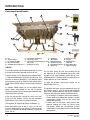
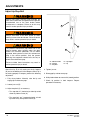
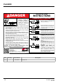
CentraAir® PATENT PENDING Dock Leveler Owner’s / User’s Manual DLM® • Division of Systems, Inc. • W194 N11481 McCormick Drive • Germantown, WI 53022 800.643.5424 • fax: 262.255.5917 • www.docksystemsinc.com • [email protected] Printed in U.S.A. Copyright © 2015 Manual No. 4111-0043 Jan 2015 Oct 2015 Table of Contents Safety Page Recognize Safety Information.............................................................. General Operational Safety Precautions............................................. Operational Safety Precautions............................................................ Maintenance Safety Precautions.......................................................... Safety Decal’s......................................................................................... Owner’s User’s Responsibilities.......................................................... Introduction General Information,.............................................................................. Dock Leveler Stock Specifications...................................................... Component Identification...................................................................... Theory.................................................................................................... 1 1 2 4 5 6 7 7 8 8 Installation Prepare Pit.............................................................................................. 9 Prepare Dock Leveler........................................................................... 10 Install Dock Leveler.............................................................................. 12 Install Control Panel and Wiring......................................................... 16 Placard Installation............................................................................... 17 Air Line Installation............................................................................... 18 Put New Leveler Into Service.............................................................. 22 Operation Operating Instructions......................................................................... 24 Ramp Loading/Unloading Instructions......................................... 25 End Loading/Unloading Instructions............................................ 26 Maintenance Service Dock Leveler Safely................................................................ 27 Periodic Maintenance........................................................................... 28 Adjustments Adjust Lip Latch and Lip Actuator Springs....................................... 30 Adjust Lip Stop..................................................................................... 32 Snubber Spring Assembly................................................................... 33 Troubleshooting Troubleshooting.................................................................................... 34 Parts Electrical................................................................................................ 36 Control Box........................................................................................... 37 Air Control Valves................................................................................. 38 Below Dock Control.............................................................................. 41 Bellows and Regulator......................................................................... 43 Frame and Platform.............................................................................. 44 Lip Activation........................................................................................ 46 Weather Seal......................................................................................... 47 Placard .................................................................................................. 48 Miscellaneous Customer Information.......................................................................... 49 Warranty................................................................................. Back Cover SAFETY Recognize Safety Information General Operational Safety Precautions Safety - Alert Symbol The Safety-Alert Symbol identifies import safety messages on equipment, safety signs, in manuals, or elsewhere. When you see this symbol, be alert to the possibility of personal injury of death. Follow the instructions in the safety message. Read and understand the Owner’s/User’s manual and become thoroughly familiar with the equipment and its controls before operating the dock leveler. Never operate a dock leveler while a safety device or guard is removed or disconnected. The use of the word DANGER signifies the presence of an extreme hazard or unsafe practice which will most likely result in severe injury or death. The use of the word WARNING signifies the presence of a serious hazard or unsafe practice which may result in serious injury or death. The use of the word CAUTION signifies possible hazard or unsafe practice which could result in personal injury. The use of the word NOTICE is to draw attention to a procedure that needs to be followed to prevent machine damage. Indicates a type of safety sign, or separate panel on a safety sign, where safety-related instructions or procedures as described. 4111-0043 — Jan 2015 Oct 2015 Never remove DANGER, WARNING, or CAUTION signs or Decal’s on the equipment unless replacing them. one Z g tin a r e Op on Z g tin a r O pe e Do not start the equipment until all unauthorized personnel in the area have been warned and have moved outside the operating zone. Remove any tools or foreign objects from the operating zone before starting. Keep the operating zone free of obstacles that could cause a person to trip or fall. 1 SAFETY Operational Safety Precautions Learn the safe way to operate this equipment. Read and understand the manufacturer’s instructions. If you have any questions, ask your supervisor. Stay clear clear of of dock dockleveling levelingdevice devicewhen whentransport transport vehicle is entering or leaving area. thethe dock leveling device if if Do not not move moveororuse use dock leveling device anyone is under or in front of it. Keep hands hands and and feet feetclear clearofofpinch pinchpoints. points.Avoid Avoid putting any part of your body near moving parts. Chock/restrain all transport vehicles, Never remove the wheel chocks until loading or unloading is finished and transport driver has been given permission to drive away. Do not use a broken or damage dock leveling device. Make sure proper service and maintenance procedures have been performed before using. Make sure lip overlaps onto transport vehicle bed at least 4 in. (102 mm). Keep a safe distance from both side edges. 2 4111-0043 —Jan 2015 Oct 2015 SAFETY Do not use dock leveling device if transport vehicle is too high or too low. Do not overload the dock leveling device. Do not operate any equipment while under the influence of alcohol or drugs. Do not leave equipment or material unattended on dock leveling device. 4111-0043 — Jan 2015 Oct 2015 3 SAFETY Maintenance Safety Precautions ALWAYS disconnect electrical power source and ground wire before welding on dock leveler. DO NOT ground welding equipment to any hydraulic or electrical components of the dock leveler. Always ground to the dock leveler frame. Hydraulic and electrical power must be OFF when servicing the equipment. For maximum protection, use an OSHA approved locking device to lock out all power sources. Only the person servicing the equipment should have the key to unlock the device. Failure to follow these instructions may result in damage to dock leveler and/or serious personal injury or death. DO NOT grind or weld if hydraulic fluid or other flammable liquid is present on the surface to be ground or welded DO NOT grind or weld if uncontained hydraulic fluid or other flammable liquid is present. Stray sparks can ignite spills or leaks near the work area. Always clean up the oil leaks and spills before proceeding with grinding or welding. Always post safety warnings and barricade the work area at dock level and ground level to prevent unauthorized use of the unit before maintenance is complete. Always keep a fire extinguisher of the proper type nearby when grinding or welding. Failure to follow these instructions may result in serious personal injury or death. ALWAYS stand clear of dock leveler lip when working in front of the dock leveler. Failure to do this may result in serious personal injury or death. A maintenance prop permanently attached and hinged to the unit with means for lock out/tag out requirements (per OSHA 1910.147) is included with each pit style dock leveler. In addition, it is recommended and good safety practice to use an additional means to support the dock platform and lip anytime when physically working in front of or under the dock leveler. This additional means may include, but not limited to a boom truck, fork truck, stabilizing bar or equivalent. 4 4111-0043 —Jan 2015 Oct 2015 SAFETY Safety Decal’s 5.06" DANGER 1751-0727 CRUSH HAZARD Maintenance prop must support leveler behind bar. Do not force maintenance prop forward of bar to support lip. Failure to comply will result in death or serious injury. Refer to owner’s/user’s manual for proper use. 2.40" Every 90 days (quarterly) inspect all safety labels and tags to ensure they are on the dock leveler and are easily legible. If any are missing or require replacement, please call 1-800-643-5424 for replacements. 1751-0730 (x2) 1751-0727 Rev A Control Box Size: 9.12" Decal Size: 5.06 x 2.40 File Name: 1751-0727 Rev A SAFETY INFORMATION DANGER 3.25" Unsupported dock leveler ramps can lower unexpectedly. Before allowing vehicle to leave the dock always: Ensure no equipment, material or people are on dock leveler. Return dock leveler to its stored position at dock level. Failure to follow posted instructions will result in death or serious injury. OPERATION 1. Read and follow all instructions and warnings in owner’s/user’s manual. 2. Use of dock leveler restricted to trained operators 3. Always chock trailer wheels or engage truck restraint before operating dock leveler or beginning to load or unload. 4. Never use hands or equipment to move ramp or lip 5. Before activating dock leveler: Ensure trailer is backed in against bumpers. Remove any end loads if required. Check trailer alignment to avoid lip interference. If lip does not lower to trailer bed, reposition vehicle. 6. Ensure truck bed supports extended lip or leveler frame supports the ramp before driving on ramp. 7. Stay clear of hinges and front and sides of moving dock leveler. 8. N e v e r u s e d a m a g e d o r malfunctioning dock leveler. Report problems immediately to supervisor. MAINTENANCE/SERVICE 1. Read and follow all instructions, warnings and maintenance schedules in the owner’s/user’s manual. 2. Maintenance/Service of dock leveler restricted to trained personnel. 3. Place barriers on the driveway and dock floor to indicate service work is being performed. 4. DO NOT ENTER PIT unless dock leveler is securely supported by maintenance prop. 5. If electrically powered turn off and use OSHA lockout/tagout procedures. Call 262.255.1510 for replacement placards, warning labels, or owner’s/user’s manuals. (decal placed in same position on both sides) Control Box Size: Decal Size: 9.12 x 3.25 File Name: 1751-0730 Rev A 1751-0329 (x2) DO NOT FORK THIS SIDE (decal placed in same position on both sides) Control Box Size: Decal Size: 13 x 2 File Name: 1751-0329 1751-0330 (x2) FORK HERE (decal placed in same position on both sides) Control Box Size: Decal Size: 5.375 x 1.75 File Name: 1751-0330 REV B 1751-0729 1.02" 8.72" DANGER CRUSH HAZARD Do not work under dock leveler unless this maintenance prop has been secured in the upright position. Failure to comply will result in death or serious injury. See owner’s/user’s manual for proper procedures. 1751-0729 Rev A 5.05" Control Box Size: Decal Size: 8.72 x 1.02 File Name: 1751-0729 Rev A DANGER 1751-0731 2.40" CRUSH HAZARD Rotate prop to maintenance position. Open the pin latch and insert through the maintenance prop housing. Close the pin latch to secure prop. Use every time dock leveler is serviced. Failure to comply will result in death or serious injury. 1751-0731 Rev A Control Box Size: Decal Size: 5.05 x 2.40 5.92" File Name: 1751-0731Rev A DANGER 2.36" 1751-0726 CRUSH HAZARD DO NOT ENTER PIT unless dock leveler is securely supported by maintenance prop. Place barriers on driveway and dock floor to indicate service work being performed. Failure to comply will result in death or serious injury. Refer to owner’s/user’s manual for proper maintenance procedures. 1751-0726 Rev A Control Box Size: Decal Size: 5.92 x 2.36 File Name: 1751-0726 Rev A 4111-0043 — Jan 2015 Oct 2015 5 OWNER’S/USER’S RESPONSIBILITIES 1. The owner/ user should recognize the inherent dangers of the interface between the loading dock and the transportation vehicle. The owner/ user should, therefore, train and instruct all operators in the safe operation and use of the loading dock equipment in accordance with manufacturer’s recommendations and industry standards. Effective operator training should also focus on the owner’s/user’s company policies and operating conditions. Maintaining, updating and re training all operators on safe working habits and operation of the equipment, regardless of previous experience, should be done on a regular basis and should include an understanding and familiarity with all functions of the equipment. Owner’s/user’s shall actively maintain, update and retrain all operators on safe working habits and operations of the equipment. 2. The manufacturer shall provide to the initial purchaser all necessary information regarding Safety Information, Operation, Installation and Safety Precautions, Recommended Initial and Periodic Inspections Procedures, Planned Maintenance Schedule, Product Specifications, Troubleshooting Guide, Parts Break Down, Warranty Information, and Manufacturers Contact Information, as well as tables to identify the grade(slope) for all variations of length or configuration of the dock leveling device and information identifying the maximum uncontrolled drop encountered when sudden removal of support while in the working range of the equipment. 3. It is recommended that when the transportation vehicle is positioned correctly in the dock opening and in contact with both bumpers, there shall be a minimum of 4.00 inches (100mm) overlap of the leveling device and the transportation vehicle at all times during the loading and unloading process. 4. The Owner/User must review all name plates, placards, decals, instructions and posted warnings and place the same in view of the operator or maintenance personnel for whom such warnings are intended for. Contact manufacturer for any replacements. 5. Manufacturer’s recommended periodic maintenance and inspection procedures in effect at the date of shipment shall be followed at all times. Written documentation of maintenance, replacement parts or damage should be retained. In the event of damage notification to the manufacturer is required. 6. Loading dock equipment that has been structurally damaged or has experienced a sudden loss of main support while under load (such as what might occur when a transport vehicle pulls out from under the leveling device) shall be removed from service, inspected by a manufacturer’s authorized representative, and repaired or replaced as needed before being placed back in service. 7. Any modifications or alterations of loading dock equipment shall only be done with prior written approval from the manufacturer and the same shall be at least as safe as the original equipment was prior to the modification and shall also satisfy all safety requirements of the manufacturer for the particular application of the leveling device. 8. When industrial moving devices are being used in the loading or unloading of product from the transportation vehicle, this vehicle shall have the brakes and wheel chocks applied appropriately or all other positive restraining device shall be fully utilized. It is recommended that transport vehicles with airride suspension systems shall have its air exhausted prior to performing loading and unloading operation to minimize transport vehicle bed drop. 9. Loading dock safety equipment should never be used outside of its intended use, vertical working range, or capacity. Please consult the manufacturer if you have any questions as to the use, vertical working range or capacity of the equipment. Only properly trained and authorized personnel should operate the equipment. 10. When selecting loading dock safety equipment, it is NOTICE to consider not only present requirements but also future plans and any possible adverse conditions, environmental factors or usage. 6 4111-0043 —Jan 2015 Oct 2015 INTRODUCTION General Information Dock Leveler Stock Specifications CentraAir®Series dock levelers are available in the following sizes, weight capacities, and options: Width: 6 ft (1828.8 mm) 6-1/2 ft (1981.2 mm) 7 ft (2133.6 mm) Length 6 ft (1828.8 mm) 8 ft (2438 mm) 10 ft (3048 mm) Congratulations on your choice of a DLM® dock leveler. This manual covers the CentraAir® dock leveler. Designed by DLM to be a marvel of simplicity and efficiency, your dock leveler, when properly installed, will provide many years of trouble-free performance with an absolute minimum of maintenance. Its revolutionary air bellows system efficiently controls and operates every function. To obtain maximum performance and longest possible use, a simple program of preventive maintenance is recommended. Capacity (CIR*) 25,000 lb (11 30,000 lb (13 35,000 lb (15 40,000 lb (18 45,000 lb (20 50,000 lb (22 340 608 876 144 412 680 kg) kg) kg) kg) kg) kg) * CIR (Comparative Industry Rating) All docks are available in 115V Controls, pneumatic push button or lanyard. Q The CentraAir® dock has three control options. Lanyard cable, electrical control or pneumatic control, which allows operation of the dock leveler functions. Each CentraAir® leveler unit and control panel have been factory assembled and tested to ensure satisfactory operation. To illustrate which connections are to be made in the field at installation, electrical drawings and pneumatic hose drawings are included with each order or by contacting Technical Services. Once again, thank you and congratulations on your purchase of a DLM CentraAir® dock leveler. 4111-0043 — Jan 2015 Oct 2015 7 INTRODUCTION Component Identification E O A N S C R M S D T B K L Q G J F I A — Lip B — Lip Assist Rod C —Lip Linkage Assembly D — Lip Latch Assembly E — Lip Maintenance Prop Pivot F — Lip Actuator Chain Spring J — Air Bellows G — Lip Actuator Chain K — Main Frame H — Lip Actuator Chain Adjustment Link L — Maintenance Prop (not shown) M —Toe Guard (2 used) I — Lip Keepers (2 used) N —Raise Button (Electric) O —Safety Legs P P —Air Control Valve Q —Lanyard R —Filter/Regulator Lubricator S —Raise Button (Air) T —Lip Assist Spring THEORY The CA dock leveler uses Compressed Air with a lanyard or (single push button) operation for ease of use. The dock leveler can be operated three different ways. 1.) Depress RAISE button (N) on the control panel. This activates an electric solenoid (P). The solenoid allows compressed air into the air bellows causing the platform to rise. When RAISE button is released the platform to lower. 2.) Depress RAISE button (S) on the control panel. Allows allows compressed air into the air bellows causing the platform to rise. Releasing the RAISE button allows the platform to lower. 3.)Pull up and hold the Lanyard (Q) chain in the rear of the unit until platform and lip are fully extended. Releasing the chain allows the platform to lower. The regulator (R) supplies 95 PSI to the bellows. (J) When the platform rises to with in 2-3 in. (51-76. mm) of its full raised height, the lip spring (F) and lip actuator chain (G), causes the lip linkage assembly to push the lip out and up. 8 The lip assist spring (S) also assist pushing the lip out. When the lip is fully extended, the lip latch cable engages the lip latch assembly, locking the lip in the extended position. The dock leveler has reached its full height when the lip is fully extended. To lower the platform, release the lanyard (Q) or RAISE button (N or S). The platform will lower until the extended lip rests on the transport vehicle. If the lip did not fully extend or there is no transport vehicle at the dock the platform will lower until one of the following conditions occur: • Lip is resting in lip keepers (cross-traffic position). • Leveler went to the below-dock position, lip folds automatically, leveler rests on the safety legs (below dock position). • Leveler went to the below dock position with operator holding the safety leg retract cable (not shown), safety legs are retracted, lip folds automatically causing dock to rest in the full below dock position. 4111-0043 —Jan 2015 Oct 2015 INSTALLATION Prepare Pit A 10" 14" B C 7" 7" E E D A—Distance (Pit Width) (Front and Rear) B— Distance (Dock Floor-to-Pit Floor) (All Four Corners) C— Distance (Pit Length) (Both Sides of Pit) D— Distance (Pit Corner‑to‑Corner) (Top, Bottom, and Both Sides) Before lowering the dock leveler into the pit, the following must be performed: Post safety warnings and barricade the work area at dock level and ground level to prevent unauthorized use of the dock leveler before installation has been completed. Failure to follow the installation instructions can result in damage to dock leveler, the facilities, and/ or serious personal injury or death. 1. Remove all debris from the pit and sweep the pit clean. 2. Check the entire dock leveler pit for proper construction according to approved/certified pit drawings. Make sure pit is square by making the following measurements: Only trained installation professionals with the proper equipment should install this product. •Measure pit width distance (A) at both front and rear of pit. •Measure dock floor-to-pit floor distance (B) at all four corners. • Measure pit length distance (C) at both sides. •Measure corner-to-corner (crisscross) distance (D) at both sides. Take measurements at dock floor level and at pit floor level. DO NOT remove the shipping bands around the dock leveler lip until instructed to do so. If any measurement is off by more than 1/8 in. (3.18 mm), contact Technical Services before proceeding. When Required: 3. Make sure the field junction box for the dock leveler (E) is at the correct location per pit diagrams. 4. Make sure the conduit for the air lines(E) are at the correct location per the pit diagram 4111-0043 — Jan 2015 Oct 2015 9 INSTALLATION Prepare Dock Leveler A DO NOT remove the shipping bands (B) around the platform lip and leveler frame at this time. The shipping bands are needed to hold the leveler together during the installation process. 1. Remove any control panel and bumpers that may be banded to the frame of the dock leveler. DO NOT remove the shipping bands (B) around the platform lip and leveler frame at this time. B A— Lifting Bracket (2 used) B — Shipping Bands DLM® dock levelers are designed with installation in mind. Each unit is shipped with lifting brackets (A) fastened to the platform side joists. DO NOT over tighten the lifting bracket hardware. Over tightening can damage the weather seal, if equipped. NOTE: Overall width of platform and lifting brackets (A) must be kept to a minimum to prevent interference between the lifting brackets and the pit walls as the dock leveler is lowered into the pit. 2.Make sure the mounting hardware of lifting brackets (A) is snug. The brackets should pivot relatively freely on the mounting cap screw. DO NOT over tighten. The dock leveler is heavy. Use a lifting device and chains with the appropriate lifting capacity and reach. Always use the lifting brackets provided with the unit whenever lowering or lifting a dock leveler into or out of a pit. Failure to follow these instructions may result in damage to dock leveler and/or serious personal injury or death. CFM Leveler #s Recommended Compressor Size 7.3 3-6 1.5 HP 20 GAL @ 90 PSI 17.5 6 & up 5 HP 60 GAL @100 PSI 3.Attach lifting chains to lifting brackets (A) and to a lifting device (i.e., hoist or fork truck) having the appropriate lifting capacity and reach. 4.Remove wood blocks that maybe attached to the leveler frame before putting the dock leveler into the pit. 5. Raise the leveler to allow the leveler sit on the maintenance prop. Remove 3 plastic ties, 2 Rear, 1 Front before lowering into pit Compressor pump MUST be filled with appropriate oil prior to initial start up. Refer to manufactures manual for proper maintenance procedure. 1751-1037 10 4111-0043 —Jan 2015 Oct 2015 INSTALLATION This page intentionally left blank 4111-0043 — Jan 2015 Oct 2015 11 INSTALLATION Install Dock Leveler Shim Stacking Methods M N O S P R Q E D C T A— Distance (Leveler Frame Height) B— Shim Locations (Under Rear Vertical Supports) C— Shim Location (Under Lip Keepers) D— Shim Locations (Under Maintenance Prop) E— Shim Locations (Under Lip Spring) F— Dock Floor G— Rear Pit Curb Angle H— String I— Rear Hinge Frame Angle J— Distance (Dock Floor-toPit Floor) 12 K— Dock Leveler Frame M — Pyramid (Preferred) N— Stepped (Acceptable) O— Offset (Not Acceptable) P — Straight (Not Acceptable) Q— Removable Frame Section R— Shim Location (Bellows Mounting Plate, Both sides) S— Shim Locations T — Shim between lip keeper curb angle when required. F J G H I A B K 4111-0043 —Jan 2015 Oct 2015 INSTALLATION NOTE:DLM® dock levelers are designed with a nominal 1/2 in. (12.7 mm) shimming distance to allow for pit inconsistencies. 1.Determine height of shim stack (B) for each shim location (S) by performing the following: a.Measure leveler frame height distance (A). 4.For all CentraAir® models, put a 1/4 in. (6.6 mm) thick shim at locations (C,D and E). NOTE: A 1/4 in. (6.6 mm) thick shim at locations (C,D and E) is used only as a starting point. The final shim stack height will be determined after dock leveler is lowered into the pit. b. Measure dock floor-to-pit floor distance (J) at each shim location (B). Write down the dimensions obtained at each location. c.Subtract distance (A) from distance (J) to obtain the shim height. R epeat for each shim location. The minimum size of the shim that contacts the leveler frame (i.e., the top shim of each shim stack) must be at least 4-1/2 x 4-1/2 in. (114.3 x 114.3 mm) to support the full width of the hoist cylinder / storage prop weldment. Use the thickest shim stock possible for stability and weld penetration purposes. DO NOT use multiple layers of 1/8 in. (3.18 mm) or thinner shim stock. 2. Using the results obtained in step 1, create the individual shim stacks on the pit floor at locations (5). Build each shim stack (B) using the pyramid method (M) (preferred) or stepped method (N) with the top shim having a minimum size of 4-1/2 x 4-1/2 in. (114.3 x 114.3 mm) and each successive lower shim being larger so the shims can be welded together using a fillet weld. DO NOT use offset method (O) or straight method (P). NOTE: To assist in obtaining an accurate measurement of distance (A), use a string (H) pulled tight across the pit opening, directly over the shim locations. 3.Verify that each shim stack is at the correct height by measuring distance (A) [top of shim stack (B) to dock floor]. 4111-0043 — Jan 2015 Oct 2015 The dock leveler is heavy. Use chains and a lifting device with the appropriate lifting capacity and reach. Failure to do so may result in damage to dock leveler and/or serious personal injury or death. 5. Using an appropriate lifting device connected to the lifting brackets, lower dock leveler into the pit so rear hinge frame angle (I) is tight against rear pit curb angle (G) across full width of the leveler frame. 6.Allow rear of dock leveler to rest on the rear shims while keeping the front of the dock leveler level with the dock floor. DO NOT grind or weld if hydraulic fluid or other flammable liquid is present on the surface to be ground or welded. DO NOT grind or weld if uncontained hydraulic fluid or other flammable liquid is present. Stray sparks can ignite spills or leaks near the work area. Always clean up the oil leaks and spills before proceeding with grinding or welding. Always keep a fire extinguisher of the proper type nearby when grinding or welding. Failure to follow these instructions may result in serious personal injury or death. 13 INSTALLATION B A C C D D E F G A— Front of Dock Pit B— Dock Leveler Frame 3/8 in. (9.5 mm) 6 in. (152 mm) C— Side Pit Curb Angle D— Gap [3/4 in. (19 mm) Minimum] 8.With rear hinge frame angle (F) tight against rear pit curb angle (G), perform/check the following: •Pry between the platform and rear hinge frame angle at locations (E) to make sure rear edge of platform is parallel to the rear hinge frame angle (F). •Gap (D) must exist equally along both sides of leveler so weather seal (if equipped) will not bind during dock leveler operation. 14 H E— Pry Locations F— Rear Hinge Frame Angle G— Rear Pit Curb Angle H— Flare Bevel Weld, Typical (To Fit Spacing) 9.If gap (D) cannot be obtained equally at both sides of leveler, grind or add material at the rear edge of rear hinge frame angle (F) as needed. 10.Allow the dock leveler to rest fully on the shim stacks. Check that a smooth and level transition exists between the dock floor and the dock leveler platform. Add or remove shims as necessary until a smooth transition is obtained. 11.If leveler cannot be squared and/or made level as instructed in steps 8 — 10, contact Technical Services. 4111-0043 —Jan 2015 Oct 2015 INSTALLATION 12. W ith the leveler square in the pit and flush with the surrounding dock, remove the banding on the lip of the leveler. 13.Lift leveler with appropriate machinery. Two people are required to engage the maintenance prop: one person to operate the lifting device, the other person to engage the maintenance prop. 14. Slowly raise the platform. Check for binding as platform is being raised. 15.If binding occurs, lower the platform. Reposition leveler and/or add or remove shims as necessary. Slowly raise platform again. If platform still binds, contact Technical Services for further instructions. 16.All CentraAir® models - Once leveler is flush, square and does not bind: DO NOT use the maintenance prop to support the raised platform until the maintenance prop has been properly shimmed and welded. The shims must be welded to each other, the leveler frame, and to the front pit curb steel. Failure to do this may result in serious personal injury or death. a. Install shims under maintenance prop (D) where prop attaches to leveler frame. Make sure prop is solidly shimmed. DO NOT weld before disconnecting all electrical components. b.Using appropriate machinery, raise the dock to the fully open position. DO NOT weld before removing air bag, air bag support pallet and hoses from leveler. c. R aise maintenance prop to the service (upright) position and lock prop in this position using an OSHA approved locking device. Protect or remove the blower motor before welding. 17.Remove air bellows from the leveler by unbolting the bellows from the frame and the deck or wrap bellows with fire proof blanket to protect from weld sparks and splatter. Failure to follow these instructions may result damage to these components from stray sparks and weld splatter. When drilling access hole in the control box, DO NOT penetrate too deep, components may be damaged. DO NOT turn control upside down to drill any access holes. To prevent damaged to electrical components from debris cover components prior to drilling Seal all conduit entrances to prevent moisture from entering the control box. DO NOT use compressed air to clean control box. Recommended to vacuum debris from inside. 4111-0043 — Jan 2015 Oct 2015 15 INSTALLATION The electrical power must be OFF prior to electrical installation. For maximum protection, use an OSHA approved locking device to lock out all power sources. Only the person installing the equipment should have the key to unlock the power source. Failure to follow these instructions may result in serious personal injury or death. DO NOT weld continuously along the full length of the rear hinge frame angle. This can put unnecessary stress on the leveler components, causing the leveler to malfunction and shorten the life span of the affected components. NOTE: The illustration on page 14 shows a typical weld pattern. The weld pattern will vary slightly depending on size of dock leveler. 18. With the rear hinge frame angle (F) tight against the rear pit curb angle and flush with the curb angle (G), weld the rear hinge frame angle (F) to the rear pit curb angle (G) using a 3/8 in. (9.5 mm) flare bevel skip weld — each weld being 6 in. (152 mm) long. DO NOT connect the dock leveler electrical wiring and ground connections until all welding has been completed. DO NOT ground welding equipment to any hydraulic or electrical components of the dock leveler. Always ground welding equipment to the dock leveler frame, NEVER to the platform. Failure to follow these instructions may damage the motor, wiring, and/or control panel. Shim Stacking Methods N P Q R * For left/right orientation of dock leveler, see inside back cover of this manual. 16 Start at each end with a 6 in. (152 mm) long weld. Space all the other welds out evenly leaving approximately 6 in. (152 mm) space between each weld. 19.All model levelers: Install shims at locations (B, p.11) using the pyramid or stepped shimming method. Make sure the platform is level from sideto-side as well as from front-to-back and flush with dock floor. 20. Weld front of dock leveler frame (B) to shims located under the keepers, then weld the shims to the front pit curb steel. 21.Finish weld all shims using a fillet weld. •Weld all shims within each shim stack to each other, then weld the shim stack to the leveler frame. •Weld the front leveler frame shim stacks to the front pit curb steel. 22.When all welding has been completed, paint all the welds and shims. Make sure the platform is properly supported in the raised position before entering the pit to finish weld the shims. Failure to do this may result in serious personal injury or death. 4111-0043 —Jan 2015 Oct 2015 PLACARD Placard Installation Instructions • Owner is responsible for the installation and placement of product placards. • Make sure placard is in plain view of dock leveler operations. • Suggested placement of placard is near control box attached to electrical conduit by using nylon tie. If there is no control box present, mount placard on wall to the immediate left of leveler at eye level. Control Box Placard Nylon Tie (Placard placement shown as reference only.) Conduit 4111-0043 — Jan 2015 Oct 2015 17 INSTALLATION Overhead Air Supply Above Door Pneumatic Supply Kit #6106-0016 See Page 21 Supply From Regulator 1/2 or larger Verify By Systems Inc. Valve 1/2 NPT to 3/8 tube Provide by Systems Pilot Supply Control Box to To Air Bellows 1/2 line Provided by Others 3/8 line Installed at Factory 3/8 line Provide By Systems 18 4111-0043 —Jan 2015 Oct 2015 INSTALLATION Underground Air Supply New Construction Kit# 6101-0018 See Page 21 Pilot Supply Control Box to To Air Bellows Valve End run, Tee NOT Required. Supply From Regulator 1/2 line Provided by Systems 3/8 line Installed at Factory 3/8 line Provide By Systems 4111-0043 — Jan 2015 Oct 2015 19 INSTALLATION Lanyard Air Supply See Page 21 To Air Regulator To Air Bellows Electric/ Pneumatic Controls See Page 21 To Control Panel Air Regulator To Air Bellows To Air Regulator 3/8 line Installed at Factory 3/8 line Provide By Systems 20 4111-0043 —Jan 2015 Oct 2015 4111-0043 — Jan 2015 Oct 2015 R BE T KI 6106-0013 6106-0014 6106-0015 6106-0016 6106-0017 6106-0018 M NU Overhead air supply New construction lever operated valve electric pushbutton operation pneumatic push button 60' 30' 30' 60' 60' 3/ Overhead air supply Retrofit lever operated valve electric pushbutton pneumatic push button 6106-0014 6106-0014 6106-0016 Kit # Underground air supply New construction lever operated valve electric pushbutton pneumatic push button 6106-0017 6106-0017 6106-0018 Kit # 10 5 1 1 TBD 1 1 TBD 1 1 1 The amount of 1/2" tubing varies by job. It is based on the door centerline and the distance to the compressor feed line fitting. 1 1 1 1 1 1 1 1 4 2 6 4 12 rev A revised 7/30/2014 d 2 ng 8" 8" 8 2" 09 e e ow er bi an 001 te te 3/ 242 3/ 000 1/ -00 lb bb 260 " tu e n n h h o u 0 6 2 t r o o n 6 it 6 it / ne 1 T 01ni 260 ni 244 io 241 w 10 mp 01-0 w 610 ) 1 10 l y 00 NP 93 un 1-0 " u 1-0 " u 1-0 (1 tg 6 a 21 ve 6 ve gs he 84-0 l l l / " 2 8 " t a a n C d f /2 g 1/ 930 3/ 930 /8 930 e ye R9 fw " f v tgs f v ti ol of 3/8 g 1 bin ub one ng ng of e f of e fit g3 i i p T n t t t t t n i i i t t ) u u ub u b tt tu 2" tt 2" sh Fi Fi Sh (1 Fi Sh t Sh tu Fi 1/ 1/ cu ng bi tu 001 n lo 0-0 ny 98 " R 8 6106-0013 6106-0013 6106-0015 Kit # MISC PARTS REQUIRED FOR INSTALLATION OF CENTRA AIR DOCK LEVELERS INSTALLATION 21 Placard Installation Instructions INSTALLATION • Owner is responsible for the installation and placement of product placards. • Make sure placard is in plain view of dock leveler operations. • Suggested placement of placard is near control box attached to electrical Install Control Panel and Wiring or Pneumatic Lines conduit by using nylon tie. If there is no control box present, mount placard on wall to the immediate left of leveler at eye level. A The electrical power must be OFF prior to electrical installation. For maximum protection, use an OSHA approved locking device to lock out all power sources. Only the person installing the equipment should have the key to unlock the power source. Failure to follow these instructions may result in serious personal injury or death. Control Box B C Nylon Tie Placard (Placard placement shown as reference only.) Conduit D DO NOT make any final electrical connections until all welding has been completed. Failure to do this may result in serious personal injury or death. All electrical work — including the installation of the disconnect panel, control panel, and final connections to the pit junction box — must be performed by a certified electrician and conform to all local and applicable national codes. 1. Mount the push button control panel (B) so bottom of control panel-to-dock floor distance (C) is 48 in. (1219.2 mm). 2. Install pneumatic air lines to control panel. 3. Re-install the air bellows, and connect pneumatic air line. 4. After all pneumatic connections in the pit have been made, raise the leveler, disengage the maintenance prop and allow the platform to lower. 5. Install the Placard(s) (D), in close proximity to the control box and in plain sight. A— Disconnect Panel (Provided by others) B— Control Panel C— Distance, 48 in. (14 630 mm) D— Placard Electric Controls 1. Mount the push button control panel (B) so bottom of control panel-to-dock floor distance (C) is 48 in. (1219.2 mm). 2. Install electrical disconnect panel (A) if not already installed. 3. Install and connect the control wiring. 4. Re-install the air bellows, and connect air line. 5. Connect the dock leveler power cable to coil. Refer to the electrical drawings supplied with the dock leveler. 6. After all electrical connections in the pit have been made, raise the leveler, disengage the maintenance prop and allow the platform to lower. 7. Install the Placard(s) (D), in close proximity to the control box and in plain sight. 22 4111-0043 —Jan 2015 Oct 2015 INSTALLATION Put New Dock Leveler Into Service 1.Disconnect the external lifting device and chains from the lifting brackets. 2.Check that the leveler is flush with the dock floor and that the platform lip contacts both lip keepers evenly. If an excessive transition exists between the dock floor and leveler and/or lip does not contact both lip keepers evenly, contact Technical Services for further instructions. 7.When the platform lowers to the full below-dock position, the lip will fold. Pull lanyard ring (or depress and hold the RAISE button) until the lip rises just enough to clear the lip keepers, then release the lanyard ring (or RAISE button) to allow the platform to lower to the cross-traffic (stored) position (lip engages lip keepers). 8.Perform steps 5 – 7 at least four times make sure the leveler functions properly and there is no binding. 3. Install the dock bumpers as required. 4. Turn the main electrical power ON. Always stand clear of platform lip when working in front of the dock leveler. Serious personal injury or death may result. 5. Pull lanyard cable and hold until leveler platform is fully raised. OR Raise the leveler platform fully by depressing and holding the RAISE button. 6. Release lanyard cable if no transport vehicle present at the dock, the platform will lower to the full below-dock position as the lip folds. OR Release the RAISE button to lower the platform. As long as there is no transport vehicle present at the dock, the platform will lower to the full below-dock position as the lip folds. NOTE:If a transport vehicle is present, the platform will lower until the lip rests on the transport vehicle bed. (See Operating Instructions in Operation section.) 4111-0043 — Jan 2015 Oct 2015 Unless the dock leveler is equipped with a tethered remote, two people are required to engage the maintenance prop: one person to operate the unit, the other person to engage the maintenance prop. 9.Raise the platform fully. Hold the platform at this position by pulling the lanyard ring (or RAISE button) and move the maintenance prop to the service (upright) position. Release the lanyard ring (or RAISE button) to allow the platform to lower until it is resting on the maintenance prop (Lockout/ tagout). 10.Remove lifting brackets located on each side of platform. 11.Support toe guards then remove cotter pin used in shipping and carefully release the toe guards. 12.Pull lanyard ring (or depress and hold the RAISE button) until the maintenance prop drops to its stored position. Release the lanyard ring (or RAISE button) and allow the platform to lower fully. Check operation of toe-guards. 13.When the platform lowers to the full below-dock position, the lip will fold. Pull lanyard ring (or depress and hold the RAISE button) until the lip rises just enough to clear the lip keepers, then release the lanyard ring (or RAISE button) to allow the platform to lower to the cross-traffic (stored) position (lip engages lip keepers). 23 OPERATION Operating Instructions Stay clear of dock leveler when transport vehicle carrier is entering or leaving dock area. 12in. (305mm) DO NOT move or use the dock leveler if anyone is under or in front of leveler. Keep hands and feet clear of pinch points. Avoid putting any part of your body near moving parts. Failure to follow these instructions may result in severe personal injury or death. Only trained personnel should operate the dock leveler. 12in. (305mm) The MA pneumatic dock leveler is designed to compensate for a maximum ± 12 in.* (305 mm) of height difference between the loading dock and the transport vehicle bed. DO NOT use the dock leveler if the transport vehicle bed is more than 12 in. (305 mm) higher or lower than the dock floor. *service height may vary with design specifications DO NOT overload the dock leveler. DO NOT use a broken or damaged dock leveler. Make sure proper service and maintenance procedures have been performed on leveler before using. DO NOT operate any equipment while under the influence of alcohol or drugs. transport vehicle wheels must be chocked unless the vehicle restraint is used. Never remove the wheel chocks until loading/unloading is finished and transport vehicle driver has been given permission to leave. Failure to follow these instructions may result in personal injury and/or damage to equipment. Make sure platform lip rests on the transport vehicle bed with at least 4 in. (102 mm) of overlap. Maintain a safe distance from side edges of leveler during the loading/unloading process. Failure to follow these instructions may result in serious personal injury or death. 24 DO NOT leave equipment or material unattended on the dock leveler. The dock leveler operating instructions are divided into the two methods of loading and unloading: • For ramp loading and unloading, see Ramp Loading/Unloading Instructions on page 25. •For end loading and unloading, see End Loading/ Unloading Instructions on page 26. 4111-0043 —Jan 2015 Oct 2015 OPERATION Operating Instructions—Continued Below Dock Loading/Unloading Instructions Ramp Loading/Unloading Instructions NOTE:If end unloading is required, see End Loading/Unloading Instructions on page 26. NOTE:If end unloading is required, see End Loading/Unloading Instructions on page 26. For ramp loading or unloading, the CA dock leveler can be operated by pulling the lanyard chain (or depress RAISE button on the control panel (A). 7.Check to make sure transport vehicle is positioned squarely against dock bumpers. 8. Instruct driver to remain at the dock until the loading or unloading process has been completed. 1.Check to make sure transport vehicle is positioned squarely against dock bumpers. 9.Chock the transport vehicle wheels or use vehicle restraint if present. 2.Instruct driver to remain at the dock until the loading or unloading process has been completed. 10. Raise the platform by pulling lanyard ring (B) (or depressing the RAISE button (A) to fully raise the leveler and extend the lip. 3. Chock the transport vehicle wheels or use the vehicle restraint if available. A A-RAISE Button 11. W alk out on the leveler, Pull and Hold the release ring (see picture below) until the platform lowers onto the transport vehicle. Make sure there is a minimum of 4” of lip overlapping the transport vehicle. B B-LANYARD Cable 4.Extend the platform lip onto transport vehicle as follows: a.Raise the platform by pulling lanyard ring (B) (or depressing and holding RAISE button (A)). Loading/Unloading Completed - Reset Leveler A b.Pull lanyard ring (B) (or depress the RAISE button) until the lip is fully extended, then release the lanyard ring (or RAISE button (A). The platform will lower until the lip is resting on the transport vehicle bed. c. Make sure that the lip is fully extended and supported on the transport vehicle along the entire width of the platform with at least 4 in. (102 mm) of lip contacting the transport vehicle. B A—RAISE Button B-LANYARD Cable 12. W hen loading or unloading is finished, raise the platform by pulling lanyard ring (B) (or depressing and holding RAISE button (A). 13. P ull lanyard ring (B) (or hold the RAISE button (A) until the lip folds enough to clear the transport vehicle, then release the RAISE button. The lip will fold and the platform will return to the crosstraffic position. 5. Proceed with loading or unloading the transport vehicle. 14. R emove chocks from transport vehicle wheels or release the vehicle restraint if used. 6.If below dock loading is necessary, see steps 7-11. If not, proceed to step 12. 15. Indicate to driver that transport vehicle may leave the dock. 4111-0043 — Jan 2015 Oct 2015 25 OPERATION Operating Instructions—Continued End Loading/Unloading Instructions NOTE:If ramp loading is required, see Ramp Loading/Unloading Instructions on page 25. End loading or unloading can be done with the dock at the cross-traffic position or belowdock position, depending on the height of the transport vehicle bed. 1.Check to make sure transport vehicle is positioned squarely against dock bumpers. 2.Instruct driver to remain at the dock until the loading or unloading process has been completed. 3. Chock the transport vehicle wheels or use the vehicle restraint if available. 6.Pull lanyard ring (or depress the Raise button) to position the platform high enough to clear the lip keepers, but not high enough to extend the lip. 7.Walk out on the leveler, pull and hold the safety leg retract pull ring (located in the recess at the front of the platform). This will cause the lip to extend away from the lip keepers and the cross traffic safety legs to fold to allow the leveler to lower to the below dock position. 8. When the platform lip clears the lip keepers, continue to hold the pull chain as the leveler lowers to the below-dock service position. The platform will drift down to the full below-dock position. 9. Proceed with loading/unloading. End Loading/Unloading — Platform at Cross-Traffic Position. 4.If transport vehicle bed is at or above dock floor level, leave leveler at the cross-traffic position and proceed with loading or unloading. NOTE: When end unloading is finished and access to the rest of the transport vehicle is still required, the platform lip will need to be extended. See Ramp Loading/Unloading Instructions on page 25 for further instructions. 10.When the loading or unloading is finished, return the dock leveler platform to the cross-traffic (stored) position. End Loading/Unloading — Platform Too High Use Below-Dock Position. 5. If transport vehicle bed is below the dock floor level, perform steps 6 –12. 11.Pull the lanyard ring (B) (or depress the RAISE button (A)) until the lip clears the lip keepers. Release lanyard ring (or RAISE button), leveler will return to the stored or cross traffic position. 12.Remove chocks from transport vehicle wheels or release the vehicle restraint if used. 13. Indicate to the driver that the transport vehicle may leave the dock. End Loading/Unloading — Platform at Below-Dock Position. 26 4111-0043 —Jan 2015 Oct 2015 MAINTENANCE Service Dock Leveler Safely D E A B C A— Maintenance Prop B —Tag Out Device C B C —Lock out Device When service under the dock leveler is required, always lock all electrical disconnects in the OFF position after raising the platform and engaging the maintenance prop. Failure to do this may result in serious personal injury or death. Always stand clear of the dock leveler lip when working in front of the dock leveler. The maintenance prop MUST be in the service position when working under the dock leveler. For maximum protection, use an OSHA approved locking device to lock the maintenance prop in the service position. Only the person servicing the equipment should have the key to unlock the maintenance prop. Unless the dock leveler is equipped with a tethered remote, two people are required to engage the maintenance prop: one person to operate the unit, the other person to engage the maintenance prop. Failure to follow these instructions may result in serious personal injury or death. D— Lip Prop E —Valve,Air Supply Always post safety warnings and barricade the work area at dock level and ground level to prevent unauthorized use of the dock leveler before maintenance is complete. Failure to do this may result in serious personal injury or death. Whenever performing maintenance under the dock leveler platform, support the platform with the maintenance prop (A). Position the maintenance prop behind front header plate while staying clear of the lip. The Lip Prop should be used to keep the lip extended (D). Additional supports should be used to prevent the lip from collapsing if working under the leveler. Lock the maintenance prop in the service (upright) position using an OSHA approved lockout/tag out device* (B&C). Whenever servicing the dock leveler, lock the electrical power disconnect in the OFF position. Use only an OSHA approved lockout/tag out device* (B).Turn off air supply to the leveler(E). Only the person servicing the equipment should have the capability to remove the lockout/tag out devices. The Tag out devices* must inform that repairs are in process and clearly state who is responsible for the lockout condition. * Refer to OSHA regulation 1910.146. * Refer to OSHA regulation 1910.147. 4111-0043 — Jan 2015 Oct 2015 27 MAINTENANCE Periodic Maintenance A B C E D G A— Lip Hinge Area B— Lip Maintenance Prop Pivot C— Lip Link Pivots D— Platform Hinge Area E— Lip Assist Pin G— Safety leg linkage pivots Adjusting knob Clockwise increase PSI Counter Clockwise decrease PSI (H) Recommend 95 PSI Inlet Lubricator: Gentle turn clock wise until it stops then turn back 1/2 turn for factory setting. Supply line to dock leveler (F) Fill line with Kill Frost or equivalent (lubricator may not be on every unit) (G) Drain water as needed 28 4111-0043 —Jan 2015 Oct 2015 MAINTENANCE Regular maintenance must be performed on a weekly and quarterly schedule. Follow all safety precautions. Quarterly Maintenance •Perform Weekly Service Items Weekly Maintenance • Lubricate the following areas with light weight machine oil: (F)— Check Kill frost level. (may be required more frequently depending on usage) (A)— Lip hinge area unless equipped with grease fittings (apply oil to the top of the entire length of lip hinge when platform is at the full belowdock position and lip is folded). (D)— Platform hinge area (apply oil to top of all platform hinges when platform is at the full below-dock position). (C)— Lip Link pivots. (G)— Drain water (may be required more frequently depending on usage and compressor size). (H)— Verify Line Pressure is at 95 PSI. • Operate the dock leveler through the complete operating cycle to maintain lubrication. NOTE: To thoroughly inspect the platform hinge area, put the platform in the full below-dock position. •Inspect the platform hinge and the lip hinge areas. The hinge areas must be kept free of dirt and debris. Build-up of foreign material in the hinge areas will cause abnormal operation. NOTE:Apply grease to lip hinge grease fittings if equipped. • Lubricate the following areas with light-weight machine oil: (B)— Lip maintenance prop pivot • Inspect the area under the platform, around and under the air bellows. Build-up of foreign material in this area may damage air bellows components, causing abnormal operation. (G)— Safety leg linkage pivots • Lubricate the following areas with white lithium grease (if equipped with grease fittings): (A)— Lip hinge area (inject grease into all the lip hinge grease fittings). (E)— Lip assist pin. A maintenance prop permanently attached and hinged to the unit with means for lock out/tag out requirements (per OSHA 1910.147) is included with each pit style dock leveler. In addition, it is recommended and good safety practice to use an additional means to support the dock platform and lip anytime when physically working in front of or under the dock leveler. This additional means may include, but not limited to a boom truck, fork truck, stabilizing bar or equivalent. Failure to properly lubricate the dock leveler will cause abnormal operation of the leveler. 4111-0043 — Jan 2015 Oct 2015 29 ADJUSTMENTS Adjusting the Latch and Lip Actuator Spring Tension When service under the dock leveler is required, always lock all electrical disconnects in the OFF position after raising the platform and engaging the maintenance prop. Failure to do this may result in serious personal injury or death. Always post safety warnings and barricade the work area at dock level and ground level to prevent unauthorized use of the dock leveler before maintenance is complete. Failure to do this may result in serious personal injury or death. A B Always stand clear of the dock leveler lip when working in front of the dock leveler. The maintenance prop and lip maintenance prop MUST be in the service position when working under the dock leveler. For maximum protection, use an OSHA approved locking device to lock the maintenance prop in the service position. Only the person servicing the equipment should have the key to unlock the maintenance prop. Unless the dock leveler is equipped with a tethered remote, two people are required to engage the maintenance prop: one person to operate the unit, the other person to engage the maintenance prop. Failure to follow these instructions may result in serious personal injury or death. A— Lip Latch Spring Adjustment 30 B— Lip Actuator Spring Adjustment 4111-0043 —Jan 2015 Oct 2015 ADJUSTMENTS Adjusting Lip Latch Spring Tension Adjusting Lip Actuator Spring Tension This adjustment is set at the factory and should not require additional adjustment. This adjustment is set at the factory and should not require additional adjustment. Unlike mechanical levelers, the lip will not immediately begin to fold as the platform returns to the stored position. Unlike mechanical levelers, the lip will not immediately begin to fold as the platform returns to the stored position. After the platform is fully raised, and the lip extends, the lip latch is designed to hold the lip in the extended position until the platform drifts down to the below dock position. The leveler lip remains extended as the platform drifts down to the below dock position. The lip will automatically fold when the platform when the dock is resting on the safety legs in the below dock position If the lip does not remain extended check proper engagement of the lip latch. 1. Check air bellows and hoses for possible leaks. NOTE:Use two-turn increments when adjusting lip assist spring. Check lip operation after each adjustment. Repeat until proper operation is obtained. Adjust spring tension as follows: 1. Loosen jam nut (A). 2. To increase spring tension, turn nut (B) clockwise. 3. T o decrease spring tension, turn nut (B) counterclockwise. 4. Tighten jam nut. echeck operation of platform and lip. Readjust lip R latch spring tension and lip assist spring tension until proper operation is obtained. 4111-0043 — Jan 2015 Oct 2015 2. If the lip does not fully extend additional spring tension may be needed. NOTE:Use two-turn increments when adjusting lip assist spring. Check lip operation after each adjustment. Repeat until proper operation is obtained. Adjust spring tension as follows: 1. Loosen jam nut (A). 2. To increase spring tension, turn nut (B) clockwise. 3. To decrease spring tension, turn nut (B) counterclockwise. 4. Tighten jam nut. echeck operation of platform and lip. Readjust lift R spring tension and lip assist spring tension until proper operation is obtained. 31 ADJUSTMENTS Adjust Lip Stop Bolt Always post safety warnings and barricade the work area at dock level and ground level to prevent unauthorized use of the dock leveler before maintenance is complete. Failure to do this may result in serious personal injury or death. A B Always stand clear of the dock leveler lip when working in front of the dock leveler. Failure to do this may result in serious personal injury or death. C E The platform maintenance prop MUST be in the service position when working under the dock leveler. For maximum protection, use an OSHA approved locking device to lock the maintenance prop in the service position. Only the person servicing the equipment should have the key to unlock the maintenance prop. Failure to follow these instructions may result in serious personal injury or death. Check that lip (E) is fully resting on the lip keepers (D) and at the lowest part of the keeper cradle. If lip is not resting properly in keepers, perform the following adjustment. D A— Platform Frame B— Jam Nut C— Stop Bolt D — Lip Keeper E — Lip 4. Tighten jam nut. 5. Disengage lip maintenance prop. 6.Walk platform down to cross-traffic (stored) position. 1. Fully raise platform. Manually raise the lip and engage lip maintenance prop. 7. Check lip position in both keepers. Repeat procedure if necessary. 2. Loosen jam nut (B). 3.Adjust stop bolt (C) as necessary. •Turn stop bolt “in” (clockwise) to allow lip to fold closer to platform frame (A). •Turn stop bolt “out” (counterclockwise) to hold lip further away from platform frame (A). 32 4111-0043 —Jan 2015 Oct 2015 ADJUSTMENTS Snubber Spring assembly 4111-0043 — Jan 2015 Oct 2015 33 TROUBLESHOOTING When service under the dock leveler is required, always lock all electrical disconnects in the OFF position after raising the platform and engaging the maintenance prop. Failure to do this may result in serious personal injury or death. Always post safety warnings and barricade the work area at dock level and ground level to prevent unauthorized use of the dock leveler before maintenance is complete. Failure to do this may result in serious personal injury or death. Always stand clear of the dock leveler lip when working in front of the dock leveler. The maintenance prop MUST be in the service position when working under the dock leveler. For maximum protection, use an OSHA approved locking device to lock the maintenance prop in the service position. Only the person servicing the equipment should have the key to unlock the maintenance prop. Unless the dock leveler is equipped with a tethered remote, two people are required to engage the maintenance prop: one person to operate the unit, the other person to engage the maintenance prop. Failure to follow these instructions may result in serious personal injury or death. Before performing the detailed troubleshooting procedures, check the following items first: •Check all fuses and circuit breakers. Replace any blown fuse(s) with a fuse of equal specification and reset circuit. 34 •Make sure the correct voltages are present at the proper locations inside the control panel(s). 4111-0043 —Jan 2015 Oct 2015 TROUBLESHOOTING Symptom Possible Cause Solution Low Air pressure Minimum 80 PSI required at regulator, if lower check air supply. No voltage to solenoid Check breakers if okay check voltage at control box and solenoid Platform does not rase Lanyard Cable Adjustment Check Cable adjustment Incorrect Air Line Connections Verify pilot and Main supply air line connections are correct at control box. Air bladder or connecting air Check air bladder and air line repair or replace as lines punctured needed Platform rises slowly Damaged or restricted air lines Low Air pressure Check for visible obstructions that could cause binding. Remove obstructions. If no obstructions found, call Technical Services. See Platform Rises Slowly See Platform Rises Slowly See Periodic Maintenance in the Maintenance section. Low Air pressure Lip extends but does not remain extended as leveler drops. 4111-0043 — Jan 2015 Oct 2015 Minimum 80 PSI required at regulator, if lower check air supply. Dock leveler binding Platform does not rise to full height. Platform DOES rise to full height, but lip DOES NOT extend or extend fully. Replace damaged air line or remove restriction Lip actuator spring needs additional tension. Lip latch spring needs additional tension. Minimum 80 PSI required at regulator, if lower check air supply. Inspect lip actuator chain, repair or replace as needed. See Adjustment Section: Lip Latch Spring. •Increase tension as needed to keep latch engaged. •Clean any debris from lip latch area. •Lubricate as instructed in maintenance section. 35 Electrical Controls 36 4111-0043 —Jan 2015 Oct 2015 Control Box Electrical Control 4.00” A C 6.00” B 4.00” 0.5 FLA Amp Draw Item Quantity A 1 B C Part Number Description 2756-0004 Push Button Controller, (9-V0-800-0-E) PowerampLabel 2756-0006 Push Button Controller, (9-V0-800-0-E) DLM Label 1 1751-0872 Decal (English) 1 1751-0736 Decal, Arc Flash 4111-0043 — Jan 2015 Oct 2015 37 Control Box E B D Main Supply F Pilot Supply A C Item Quantity Part Number Description A 2 9301-0249 3/8 Bulkhead fitting B 1 1751-0892 Decal (English) C 1 8581-0163 Valve,Air 2 Position 3 Way (Includes Knob) D 2 9301-0248 3/8 Male Elbow E 1 2756-0001 Push Button Controller, (9-V0-800-0-E) Poweramp DECALS 2756-0003 Push Button Controller, (9-V0-800-0-E) DLM DECALS F 1 1751-0893 Decal, Supply / Pilot (English) B A Item Quantity Part Number A 1 B 1 9301-0241 9301-0244 9301-0260 38 Description Elbow 3/8 Tee 3/8 Tee 1/2 4111-0043 —Jan 2015 Oct 2015 VALVE BLOCK H A D E G L C J F B I Item Quantity Part Number A B C D E F G H I J K L 1 1 1 2 2 A/R 1 1 1 1 A/R 1 5265-0001 8103-0001 5402-0009 2101-0116 2101-0143 R980-0001 8581-0158 9512-2061 9301-0236 9301-0237 8581-0152 0521-0178 4111-0043 — Jan 2015 Oct 2015 7953-0188 Complete (A-B-C) Description Cable Assembly (Includes Pull Ring) Weight Assembly Lanyard Arm Bolt ¼” x 2” Lg Lock Nut ¼” ⅜ Nylon Air Line Valve Operator, Mechanical Lanyard Control Bracket Fitting, Straight Fitting, Elbow Clamp, Air Line (Not Shown) Down Speed Control 39 VALVE BLOCK D A B K E C Item Quantity Part Number Description A B C D E F 1 1 1 1 1 A/R 0521-0048 0521-0178 9301-0236 9301-0261 9301-0237 8581-0152 Brass Reducer 1/4 NPT to 3/8 NPT Breather / Muffler Fitting 3/8 NPT to 3/8 Tube Fitting 1/8 NPT to 3/8 Straight Fitting 3/8 NPT to 3/8 Swivel Elbow Clamp, Air line (not Shown) G 1 8583-0071 Valve Assemble I D A B C E G H 8583-0068 Complete assy Item Quantity Part Number A B C D E F G H I 2 2 1 1 1 A/R 1 1 1 2101-0008 2101-0143 4305-0580 8581-0157 0521-0178 8581-0152 9301-0236 9301-0237 8581-0159 40 Description Bolt ¼” x 2” LG (not Shown) Lock Nut ¼” (not Shown) Harness Valve Operator, Electrical ---REF--Valve, Down Speed Clamp, Air line (not Shown) Fitting, Straight Fitting, Elbow Coil, Solenoid valve 4111-0043 —Jan 2015 Oct 2015 PARTS Below Dock Control D G H I E F B A J Item Quantity A B D E F G H I J K L M N 1 1 1 1 1 1 1 1 1 1 1 1 1 4111-0043 — Jan 2015 Oct 2015 Part Number 9514-0108 9514-0109 DPLA-2122 DOTH-2075 DOTH-2356 DOTP-6647 DOTH-2356 DOTH-2374 7953-0131 4261-0004 7951-0019 2101-0216 2101-0239 Description Leg, Right Safety Assembly with Spring. Leg, Left Safety Assembly with Spring Pull Bar Assembly, Safety Leg Cap Screw, Lip Stop -11 UNC Nut,Hex 5/8-11 UNC Rod, Push Pin, Clevis * * * * Cotter Pin Safety Chain kit Ring, Chain Chain, Safety leg Quick Link Chain Snap link 41 PARTS This page intentionally left blank 42 4111-0043 —Jan 2015 Oct 2015 PARTS B F E C D A Item Quantity Part Number A 1 5811-0002 Description Air Bellows B 1 9514-0160 Top Mounting Weldment C 1 9512-2090 Pin, 49/64 X 10-¾ Lg. D 2 2101-0045 Cotter Pin E 8 2101-0273 3/8-16 UNC x 1” Lg. F 8 2101-0258 Washer B A C F F 95 PSI Recommend for best performance D Item Quantity A 1 B C D Part Number Description 8586-0008 Regulator Assembly W/ Lubricator Flow Left To Right (SHOWN). 8586-0009 Regulator Assembly W/ Lubricator Flow Right to Left. 1 8581-0154 Filler/Regulator 1 8581-0153 Oil Lubricator (Pint) 8583-0167 Oil Lubricator (Quart) R981-0001 Kill Frost (1 Pint) A/R Parts Below (not included in 8586-0008 or 8586-0009) E F A/R E 4111-0043 — Jan 2015 Oct 2015 R980-0001 Nylon Air Line 3/8 R984-0001 Nylon Air Line 1/2 9301-0236 Fitting Straight 3/8 9301-0258 Fitting Straight 1/2 43 PARTS Frame and Platform A N M B E F G C BILL OF MATERIAL ITEM QTY PART NO. DESCRIPTION 1 1 8432-1006 SNUBBER MOUNT AP SERIES 2 1 8432-1212 LIP LATCH RELEASE ARM SIZE P S Y S T E M S, Lip latch Release Arm Up Grade. Maybe required on some levers (manufactured before 4/2014) if below dock is required H J D P O W E R A M P D L M I N C. L o a d i n g D o c k E q u i p m e n t WLDT, LIP LATCH RELEASE, 2014 MATERIAL DRAWN BY KRV TOLERANCES (UNLESS OTHERWISE NOTED) FRACTIONAL: 1/32" DECIMAL: .00 = .01" .000 = .005" CHECKED BY DATE I 3/5/2014 DRAWING NO. 8434-0821 ANGULAR: 1 This print is the property of Systems, Inc. and represents a proprietary article in which Systems, Inc. retains any and all patent and other rights, including exclusive rights of use and/or manufacture and/or sale. Possession of this print does not convey any permission to reproduce, print or manufacture the article or articles shown therein, such permission to be granted only by written authorization signed by an officer or other authorized agent of Systems, Inc. thereof. K O L 44 4111-0043 —Jan 2015 Oct 2015 PARTS Frame and Platform 1 2 Item Quantity A B 1 1 C 1 D 1 E F G H 2 4 2 1 I J 3 6 K 1 L M N 1 1 2 O 2 P 1 Part Number Description See Table A 9515-____2 9202-0050 9202-0051 9202-0052 DKIT-9179 Lip, Welded Assembly Platform, Welded Assembly Pin, Lip Hinge 6’W Pin, Lip Hinge 6.5’W Pin, Lip Hinge 7’W Toe Guard Assembly 6 Foot (Both Sides and Hardware) DKIT-9180 DKIT-9181 2101-0039 2101-0163 2101-0011 8435-____1 Toe Guard Assembly 8 Foot (Both Sides and Hardware) Toe Guard Assembly 10 Foot (Both Sides and Hardware) Nylon Lock Nut, 5/16-18 UNC Washer, 5/16 in., Flat Cap Screw, 5/16-18 UNC x 1 in. Frame, 9202-0002 2101-0047 9224-0030 9224-0031 9224-0079 9201-0006 1751-0010 2101-0046 8432-0983 8432-0984 8432-0985 8434-0821 Rear Hinge Pin Cotter Pin, ¼ x 2 in. Maintenance Prop “39½ Maintenance Prop “43½ Maintenance Prop “47½ Prop Pin & Clip Decal, Model / Serial ID Cotter Pin, ¼ x 1¼ in. Lip Keeper 16” Lip Lip Keeper 18” Lip Lip Keeper 20” Lip Lip latch release Upgrade Provide dock leveler serial number, platform size, and lip size when calling or faxing orders. Provide length and width of inspection plate opening when calling or faxing orders. * For left/right orientation of dock leveler, see inside back cover of this manual. LIPS (Table A) 20K 25/30K 35K 40K 45K 50K 1 6.0 FOOT 16 0595-1500 0595-1503 0595-1506 0595-1509 0595-0512 0595-1515 1 18 0595-1501 0595-1504 0595-1507 0595-1510 0595-0513 0595-1516 20 0595-1502 0595-1505 0595-1508 0595-1511 0595-1514 0595-1517 1 6.5 FOOT 1 16 0595-1518 0595-1521 0595-1524 0595-1527 0595-1530 0595-1533 1 18 0595-1519 0595-1522 0595-1525 0595-1528 0595-1531 0595-1534 1 20 0595-1520 0595-1523 0595-1526 0595-1529 0595-1532 0595-1535 7.0 FOOT 1 16 0595-1536 0595-1539 0595-1542 0595-1545 0595-1548 0595-1551 1 18 0595-1537 0595-1540 0595-1543 0595-1546 0595-1549 0595-1552 1 20 0595-1538 0595-1541 0595-1544 0595-1547 0595-1550 0595-1553 4111-0043 — Jan 2015 Oct 2015 45 PARTS Lip Activation DPLA-0338 Complete Located on Deck Located on Lip R J W G M P Q H I E D G F U V T U O A S Q B K L M G C Item Quantity A B 1 1 C 1 D E F G H I J 1 1 2 2 1 1 1 K 1 L M N O P Q R S T U V W 1 5 1 1 1 2 1 1 1 2 1 1 46 Part Number DLIP-0305 2101-0221 9511-0156 9514-0114 9513-0097 2101-0051 2101-0004 DOTH-2163 2101-0222 2101-0223 9514-0091 5775-0004 5775-0005 2101-0220 DOTH-2210 2101-0045 0941-0006 2102-0002 DOTH-2416 DOTH-2421 DPLA-0341 DOTH-2061 DOTH-2131 2101-0308 DOTH-2065 Description Lip Assist Rod Complete 34” Lg (Includes Nuts) Washer Spring, Lip STD Spring, Lip HD Lip Latch Plate Bolt,½ x 2½ Lg Washer Nut, ½ x 13 Lock Nut Bolt, Shoulder x ½ x 1¾ Nut, Nylon lock” Prop, Lip Maintenance Kit (includes all hardware) Lip Latch Assembly (Includes Spring and Cable) 16" long Lip Latch Assembly (Includes Spring and Cable) 21" Long Bolt, ½ x 1 Lg. Washer, ½ Cotter Pin 1.00 LG Snubber Spring Chain 1/4 Grade 40/43 34 links 41 :long Lap Link 3/16 X 1" Cold Shut 5/16 Linkage Bar Bolt Shoulder Nut, Lock Nut Screw, Shoulder, 1/2 x 1.75 - 3/8-16 UNC BLK Oxide Bolt, Hex 1/2-13 X 3-3/4 LG 4111-0043 —Jan 2015 Oct 2015 PARTS Weather Seal E D Weather Seal Kits Item Quantity Part Number A B 1 1 0195-0021 0195-0033 C Description Brush Kit Includes Seal and Track, 1-1/2 in. 82" Lg. (Both Sides) Rubber Kit Includes Seal and Track, 1-1/2 in. 82" Lg. (Both Sides) Individual Replacement Seals Item Quantity Part Number C D E 1 1 1 0195-0021 0195-0033 0192-0146 Description Brush Refill, 1-1/2 in. 82" Lg. Rubber Refill, 1-1/2 in. 82" Lg. Replacement Channel G Item Quantity F 3 G 1 Part Number 0195-0044 0195-0046 0195-0047 0195-0048 F Description Rear Powerseal (Brush Seal) Foam Seal Kit 6' Foam Seal Kit 6-1/2' Foam Seal Kit 7' * Provide dock leveler serial number and size of platform when calling or faxing orders. *Provide width of weather strip when replacing existing seals 4111-0043 — Jan 2015 Oct 2015 47 PLACARD O P E R AT I N G ! DANGER • • • INSTRUCTIONS Read and follow all instructions, warnings, and maintenance schedules in the manual and on placards. Operation and servicing of dock leveler is restricted to authorized personnel. Always chock transport vehicle wheels or engage vehicle restraint and set parking brakes before operating dock leveler or beginning to load or unload. Before activating dock leveler, ensure lip avoids contact with transport vehicle sides and cargo. If lip does not lower to transport vehicle bed, reposition transport vehicle. Ensure the transport vehicle floor supports extended lip or the leveler frame (lip keepers or below dock endload supports) supports the ramp before driving on ramp. Stay clear of hinges and front and sides of moving dock leveler. Never use hands or equipment to move the ramp or lip. Never use damaged or malfunctioning dock leveler. Report problems immediately to supervisor. Always store dock leveler and remove people, material, and equipment from ramp before vehicle leaves the dock. DO NOT ENTER PIT unless dock leveler is securely supported by the maintenance prop. Disconnect power and follow proper lockout/tagout procedures for the dock leveler before entering the dock leveler pit or doing any repair or inspection under the dock leveler. • • • • • • • • FAILURE TO FOLLOW THESE INSTRUCTIONS COULD RESULT IN DEATH OR OTHER SERIOUS INJURY. Scan to view our owner’s/user’s manuals online. www.DockSystemsInc.com 1.800.643.5424 Call for additional placards, or manuals, or with questions regarding proper use, maintenance, and repair of dock leveler. Item Quantity Part Number A 1 1751-0874 48 1751-0874 Rev A POWERED DOCK LEVELERS NORMAL OPERATION 1. Raise the platform by depressing and holding the RAISE button. 2. Hold the RAISE button until the lip is fully extended, then release the RAISE button. The platform will lower until lip is resting on the transport vehicle. STORING LEVELER 1. Depress the RAISE button until the lip is completely folded. When the lip is folded, release the RAISE button. The platform will lower returning to the cross-traffic position. BELOW DOCK ENDLOADING • (HYDRAULIC ONLY) Depress and hold the RAISE button until the leveler is fully raised. As the lip starts to extend, release the RAISE button. The leveler will lower to the below dock position provided the lip extension allows the lip to clear the lip keepers. • (AIR POWERED ONLY) Depress and hold the RAISE button until the leveler is 12” above dock level. Pull the below dock level chain until the leveler passes the below dock position. • (HYDRAULIC WITH INFINITE LIP CONTROL) If equipped, raise the platform by depressing and holding the RAISE button. When the lip is just above the lip keepers, simultaneously depress and hold the RAISE button and the LIP OUT button until lip has extended beyond the lip keepers. Release both buttons. NOTE: If equipped, depressing E-STOP button will stop platform from lowering. Description Placard, CA 4111-0043 —Jan 2015 Oct 2015 MISCELLANEOUS Customer Information A A NOTE: Refer to illustration for left/right orientation of dock leveler. The model/serial number decal (A) is located on the right platform joist near the front (lip) of dock leveler. When you receive your CA-Series dock leveler, write down the dock leveler model and serial number in the form provided. This will help ensure safe keeping of the numbers in the event the model/serial number decal (A) becomes lost or damaged. Also, write down Systems, Inc.’s job number, the company that installed the dock leveler, and the original owner’s name. This will all help to identify the specific dock leveler if more information is required. When ordering, use part numbers and description to help identify the item ordered. Do not use “item” numbers. These are only for locating the position of the parts. Always give dock leveler MODEL NUMBER and/or SERIAL NUMBER. For service, call or contact: Systems, Inc. P.O. Box 309 Germantown, WI 53022 Dock Leveler Information Model ___________________________________ Serial No. ________________________________ Systems, Inc., Job No. ______________________ Original Owner Information Name ___________________________________ Address _________________________________ ________________________________ Installer Information Name ___________________________________ Address _________________________________ _________________________________ Date of Installation ________________________ Phone:(800) 643-5424 Fax: (262) 255-5917 E-mail: [email protected] 4111-0043 — Jan 2015 Oct 2015 49 STANDARD PRODUCT WARRANTY SYSTEMS, INC. warrants that its products will be free from defects in design, materials and workmanship for a period of one (1) year from the date of shipment. All claims for breach of this warranty must be made within 30 days after the defect is or can with reasonable care, be detected. In no event shall any claim be made more than 30 days after this warranty has expired. In order to be entitled to the benefits of this warranty, the product must have been properly installed, maintained and operated in accordance with all manufacturer’s recommendations and/or specified design parameters and not otherwise have been subject to abuse, misuse, misapplication, acts of nature, overloading, unauthorized repair or modification, application in a corrosive environment or lack of maintenance. Periodic lubrication, adjustment and inspection in accordance with all manufacturers’ recommendations are the sole responsibility of the Owner/User. In the event of a defect, as determined by SYSTEMS INC., covered by this warranty, SYSTEMS INC. shall remedy such defect by repairing or replacing any defective equipment or parts, bearing the cost for the parts, labor and transportation. This shall be exclusive remedy for all claims whether based on contract, negligence or strict liability. WARRANTY LIMITATIONS THE ABOVE WARRANTIES ARE IN LIEU OF ANY OTHER WARRANTIES, WHETHER EXPRESSED OR IMPLIED, INCLUDING BUT NOT LIMITED TO ANY IMPLIED WARRANTY OF MERCHANTABILITY OR FITNESS FOR A PARTICULAR PURPOSE. SYSTEMS INC. AND ITS SUBSIDIARIES SHALL NOT IN ANY EVENT BE LIABLE TO ANYONE, INCLUDING THIRD PARTIES, FOR INCIDENTAL, CONSEQUENTIAL OR SPECIAL DAMAGES OF ANY KIND INCLUDING BUT NOT LIMITED TO, BREACH OF WARRANTY, LOSS OF USE, LOSS OF PROFIT, INTERRUPTION OF BUSINESS OR LOSS OF GOODWILL. PRODUCT SPECIFIC WARRANTY “CentraAir®” SERIES LEVELER In addition to the “Standard Product Warranty” provided with all DLM® Products, Systems Inc., guarantees materials, components and workmanship to be free of defects for the following extended periods: •Structural Warranty – For a period of ten (10) years from the date of shipment, product will carry a prorated structural warranty. This warranty specifically applies to; the deck section, lip section, frame, rear hinge assembly and front hinge assembly only. This warranty covers structural repairs to or replacement of dock leveler in Systems Inc sole discretion and expense including reasonable labor, materials, freight and travel. If Systems Inc determines replacement is necessary, it will provide the original purchaser with a credit toward the purchase of the new replacement Systems Inc. product in the amount equal to the original purchase price of the warranted product F.O.B. point of manufacture, discounted on a ten year straight line basis by the number of years of use prior to replacement. • Pneumatic Warranty – For a period of four (4) years from the expiration of the Standard Product Warranty, Systems will provide replacement component parts from defective lifting system. This warranty specifically covers material and freight only and applies to; Bellows, hoses and Valves.