1
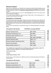
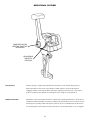
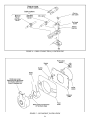
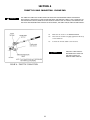
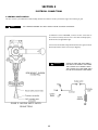
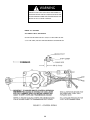
Marine Products
SL-3 Engine Controls
Owner’s Manual
This manual must be accessible to the owner/user of this Morse
marine product.
Includes installation, operation and maintenance instructions
for your Morse marine product.
Please read these Instructions through carefully and entirely
before beginning Installation.
All specifications and features are subject to change without notice.
®2006 Teleflex Marine - 212442 (Rev 1)
OPERATIONAL FEATURES
PUSH BUTTON FOR
NEUTRAL THROTTLE
OPERATION
ADJUSTABLE
THROTTLE
FRICTION
PUSH BUTTON:
Used for starting or engine warm-up. When the hand lever is in the neutral detent position,
depress the button in the center of the handle to enable operation of the throttle without
engaging forward or reverse gear. When warm-up is completed, return the lever to the neutral
position: the button will pop back out, making the control ready for normal operation.
THROTTLE FRICTION:
Adjustment of this screw enables the friction in the throttle operating mechanism to be increased
and prevent unwanted handle movement. To adjust, place the hand lever in the forward or reverse
throttle position (just beyond the shift position). Remove the cover and adjust the throttle friction
screw; turning the screw clockwise increases the friction. Care should be taken not to over tighten.
2
INTRODUCTION
The Morse® Model SL-3 Control provides both shift and throttle operation for outboards, inboard/outboards, or inboards with
hydraulic* transmissions, or small manual transmissions (Hurth®, Yanmar®) with light shifting loads of 15 lbs (6.8 kg) max. It can be
used with Tefeflex® 3300/33C type cables, Mercury®/Mariner®/Force® OEM type cables or OMC®/BRP®/Johnson®/Evinrude® OEM type
cables or cables by most other engine manufacturers.
* ALLISON®, BORG WARNER®, CATERPILLAR®, PARAGON®, TWIN DISC®, ZF®, NEWAGE®, HURTH®.
STANDARD CONTROL FEATURES
• SINGLE LEVER OPERATION.
• NEUTRAL THROTTLE WARM-UP.
• NEUTRAL SAFETY SWITCH TO PREVENT STARTING IN GEAR.
• THREE POSITION SHIFT ARM TO PROVIDE 3 TRAVEL OPTIONS.
• FRICTION DAMPER TO PREVENT THROTTLE “CREEP”.
IMPORTANT SAFETY NOTICES
TELEFLEX MARINE RECOMMENDS THE USE OF AN EMERGENCY SHUT-OFF SWITCH AS AN ADDED SAFETY MEASURE. THE SWITCH IS
DESIGNED SOLELY TO STOP THE BOAT’S ENGINE IN THE EVENT THE OPERATOR IS ACCIDENTLY REMOVED FROM THE CONTROLS.
THE SHUT-OFF SWITCH IS NOT A STANDARD PART OF THIS CONTROL, BUT CAN BE ORDERED FROM MOST MARINE DEALERS AND
DISTRIBUTORS. SEE SECTION 7 FOR SL-3 SWITCH THAT IS SUITABLE TO YOUR ENGINE TYPE.
OBSERVE CAREFULLY THE NOTES, CAUTIONS AND WARNINGS IN THIS MANUAL. THEY ARE TO ALERT INSTALLERS AND OPERATORS
OF POSSIBLE DANGERS OR OF IMPORTANT INFORMATION. WARNINGS ALONE DO NOT ELIMINATE DANGERS, NOR ARE THEY A
SUBSTITUTE FOR SAFE BOAT HANDLING AND PROPER ACCIDENT PREVENTION MEASURES.
WARNING
CAUTION
NOTE
WARNINGS:
CAUTIONS:
NOTES:
HAZARDS OR UNSAFE
HAZARDS OR UNSAFE
INFORMATION WHICH IS
PRACTICES WHICH COULD
PRACTICES WHICH COULD
IMPORTANT TO PROPER
RESULT IN SEVERE
RESULT IN MINOR INJURY
INSTALLATION OR
PERSONAL INJURIES
OR PRODUCT OR
MAINTENANCE, BUT IS
OR DEATH.
PROPERTY DAMAGE.
NOT HAZARD RELATED.
3
TOOLS NEEDED FOR INSTALLATION
OTHER EQUIPMENT NEEDED:
1.
Two (2) each Teleflex 3300/33C type cables, or two (2) each OMC/BRP OEM type cables, or two (2) each Mercury/Mariner/Force
OEM type cables. (One for throttle and one for shift).
2.
Throttle and Shift Connection Kits for engine. See Teleflex Catalog/contact your nearest Teleflex dealer.
4
SECTION 1
LOCATION OF CONTROL
1.1 Allow adequate clearance for Hand Lever swing (forward and reverse positions). See Figure 2 for Control dimensions.
1.2 Allow adequate clearance under the console for the Cables. Refer to Figure 2.
1.3 After a suitable location for the Control is determined, use the Mounting Template provided and cut & drill the mounting
holes required.
NOTE
ON ALL MODELS, THE COVER WILL HAVE TO BE REMOVED TO EXPOSE THE MOUNTING HOLES.
NOTE
SEE FIGURE 5 FOR ADDITIONAL SIDE MOUNT MODEL INSTALLATION INFORMATION.
SECTION 2
CABLE MEASUREMENT AND ROUTING
2.1 Measure from the Control position along an unobstructed path to the shift and throttle connections.
2.2 Cables lengths are measured from end to end. When a measurement is in feet and inches, specify the next whole foot.
NOTE
FOR OUTBOARD ENGINES, ADD FOUR (4) FEET (1.25 M) TO THE LENGTH OF THE CABLE FOR A LOOP TO
ALLOW FOR ENGINE SWING.
2.3 The Cable runs should minimize the number of bends and avoid any sharp bends. Make no bends in Cables less than
eight (8) inches radius (203 mm).
2.4 The Cables should be supported by using Cable Hangers or by running them through straight sections of conduit for long runs.
CAUTION
DO NOT USE CABLE HANGERS OR CLAMPS WHICH MAY CRUSH OR STRESS THE CABLES IN ANY WAY.
DOING SO MAY IMPAIR THE FUNCTION OF THE CABLE.
FIGURE 1 - TYPICAL CONTROL SYSTEMS
5
FIGURE 2 - CONTROL MEASUREMENTS
6
SECTION 3
SHIFT & THROTTLE CABLE CONNECTION – CONTROL END
NOTE
“PUSH” AND ‘”PULL” REFER TO THE DIRECTION OF CABLE MOTION TO SHIFT INTO “FORWARD”
OR TO “OPEN” THE THROTTLE.
NOTE
REFER TO THE APPROPRIATE MANUFACTURER’S MANUAL FOR SHIFT AND THROTTLE DIRECTION
AND ADJUSTMENTS.
NOTE
HOLE NUMBERS ON MECHANISM CHASSIS CORRESPOND TO HOLES IN SHIFT AND THROTTLE LEVERS.
E.G., CONNECT CABLE MOUNT TO HOLE 4 ON CHASSIS AND CABLE END FITTING TO HOLE 4 ON LEVER.
NOTE
CABLES AND WIRING SHOULD BE PRE-INSTALLED ON CONTROL BEFORE FINAL MOUNTING IS MADE.
FIGURE 3a CONTROL CABLE CONNECTING POINTS - BY SHIFT ACTUATION TYPE
OMC/BRP applications would include:
Outboards: Evinrude and Johnson
I/Os (Stern Drives): OMC, some Volvo
Mercury applications would include:
Outboards: Mercury, Mariner, most Force
I/Os (Stern Drives): MerCruiser
Inboards: Mercury and MerCruiser
(Where a particular engine brand is noted in the illustrations above, those cable mounting locations are for
OEM type cables (not the “universal” 3300/33C type)
7
FIGURE 3b CONTROL CABLE CONNECTING POINTS - BY THROTTLE ACTUATION TYPE
OMC/BRP applications would include:
Outboards: Evinrude and Johnson
I/Os (Stern Drives): OMC, some Volvo
Mercury applications would include:
Outboards: Mercury, Mariner, most Force
I/Os (Stern Drives): MerCruiser
Inboards: Mercury and MerCruiser
(Where a particular engine brand is noted in the illustrations above, those cable mounting locations are for
OEM type cables (not the “universal” 3300/33C type)
8
FIGURE 4 - CABLE CONNECTIONS, CONTROL END
FIGURE 5 - SIDE MOUNT, INSTALLATION
9
FIGURE 6 - 3300/33C CABLE
TERMINAL CONNECTION
FIGURE 7 - OMC/BRP &
MERCURY/MARINER/FORCE OEM TYPE
CABLE TERMINAL CONNECTION
10
SECTION 4
THROTTLE CABLE CONNECTION - ENGINE END
CAUTION
THE THROTTLE CABLE MUST BE DISCONNECTED FROM THE MOTOR BEFORE MAKING MOTOR IDLE
ADJUSTMENTS. ADJUSTMENT OF THE MOTOR IDLE WHILE THE THROTTLE CABLE IS STILL CONNECTED TO
THE MOTOR MAY CAUSE A JAMMING ACTION AGAINST THE IDLE STOP. AS A RESULT, THE CONTROL MAY
NOT FUNCTION PROPERLY AND DAMAGE TO THE CONTROL, THE CABLE AND/OR MOTOR COULD RESULT.
4.1
Make sure the Control is in NEUTRAL DETENT.
4.2
The Fuel Lever should rest lightly against the Idle Stop
on the carburetor
4.3
Connect the Throttle Cable to the fuel lever.
NOTE
FIGURE 8 - THROTTLE CONNECTION
11
THROTTLE CABLE MUST BE
FREE WHEN FUEL LEVER IS IN
THE IDLE POSITION TO
PREVENT HARD SHIFTING.
SECTION 5
ELECTRICAL CONNECTIONS
A. NEUTRAL SAFETY SWITCH
The SL-3 Control is provided with a Neutral Safety Switch. This Switch is used to prevent the engine from starting in gear.
NOTE
USE A BATTERY-POWERED TEST LIGHT OR TEST METER TO CHECK CONTINUITY.
6.1 With the Control in NEUTRAL, connect one wire of the tester to
the common terminal, and one wire to the ‘NO” Normally Open)
Terminal The test light MUST light.
6.2 Connect the Neutral Safety Switch between the ignition switch
(start lead) and the starter solenoid (see diagram).
CAUTION
FIGURE 9 - NEUTRAL SAFETY SWITCH
CONNECTIONS
12
CHECK TO MAKE SURE THAT THERE IS
ELECTRICAL CONTINUITY ONLY WHEN
THE CONTROL IS IN NEUTRAL. WHEN
THE CONTROL IS IN GEAR THERE MUST
NOT BE ANY ELECTRICAL CONTINUITY.
B. TRIM AND TILT SWITCHES
Refer to the wiring diagrams (Figure 10) for the correct “Trim” and “Tilt” switch connections and wire accordingly.
NOTE
ON 3 WIRE SYSTEMS, REVERSE THE BLUE AND GREEN CONNECTIONS FOR OPPOSITE
“TRIM” OPERATION.
ON 5 WIRE SYSTEMS, REVERSE THE BLUE AND GREEN CONNECTIONS FOR OPPOSITE
“TRIM” OPERATION.
DO NOT CHANGE THE RED CONNECTION.
COLOR KEY
ABBREVIATION
B = blue
Dn = down
G = green
P = purple
R = red
W = white
FIGURE 10 - “TRIM” & “TILT” SWITCH CONNECTIONS
13
WARNING
FAILURE TO FOLLOW INSTALLATION PROCEDURES AS
OUTLINED BELOW AND IN CONJUNCTION WITH THE
ENGINE MANUFACTURERS RECOMMENDATIONS MAY
RESULT IN LOSS OF SPEED CONTROL.
MORSE SL-3 CONTROL
ALL MODELS TOP & SIDE MOUNT
ON ANY INSTALLATION USING A 3300/33C TYPE CABLE OR ANY
S.A.E. TYPE CABLE, FOLLOW THE PROCEDURE AS SHOWN BELOW
FIGURE 11 - CONTROL DETAILS
14
SECTION 6
MAINTENANCE AND CORROSION PROTECTION
For maximum protection, especially in a salt water environment the Control Head and Hand Lever should be washed with fresh water
on a regular basis.
Periodically check the Control Head Mechanism for loose fasteners and signs of wear on moving parts. Keep these moving parts well
lubricated with a high-quality, moisture-displacing lubricant, such as marine grease.
Periodically check the Cables and engine connections for signs of wear and corrosion. Replace as necessary.
SECTION 7
LIST OF REPLACEABLE PARTS
Trim Switch Kit ...................................................................................................................................315590
Side Mount Tilt Switch/wire harness ...................................................................................................309509
Top Mount Tilt Switch/wire harness ....................................................................................................309514
Lanyard for Cut-off Switch (side mount) .............................................................................................311376
Cut-off Switch w/Cover (side mount) Outboards only .................................................................311380-002
Cut-off Switch Only (side mount) Outboards only .......................................................................311379-002
Cut-off Switch w/Cover (side mount) Inboards and Stern Drives (I/Os) ........................................311380-001
Cut-off Switch Only (side mount) Inboards and Stern Drives (I/Os)..............................................311379-001
Neutral Safety Switch ..................................................................................................................051801-033
REPLACEMENT PARTS KITS INCLUDE BEZEL COVER,
HAND GRIP AND NEUTRAL WARM-UP BUTTON:
Top Mount (Single) replace. parts kit ..................................................................................................316941
Top Mount (Twin) replace. parts kit ....................................................................................................316942
Side Mount replacement parts kit .......................................................................................................317002
Side Mount replacement parts kit (with cutoff switch) ........................................................................317003
PLEASE NOTE: Control levers are NOT sold separately.
Cable Nest Kit & Connection Kit..................................................................................................212151-001
(Mounts 3300/33C and BRP/OMC/Johnson/Evinrude/Merc/Mariner/Force OEM type cables to control.)
15
The Teleflex Marine division of Teleflex Incorporated, (“Teleflex Marine”) warrants its products to be free from defects in materials and
workmanship for a period of two years from the date of original retail purchase, provided, however, the warranty period for Teleflex
Marine products used commercially or in any rental or other income producing activity shall be as follows:
• Ninety days from the date of original purchase for mechanical and electrical products; and
• One year from the date of original purchase for hydraulic products.
We will provide replacement product without charge for any Teleflex Marine product covered by this warranty, which is returned
(freight prepaid) within the warranty period to the dealer from whom such products were purchased, or to us at the appropriate
address. In any such case, Teleflex Marine products found to be defective and covered by this warranty will be replaced or repaired at
Teleflex Marine’s option, and returned to the customer. Teleflex Marine’s sole responsibility under this warranty is limited to the repair
or replacement of product which is, in Teleflex Marine’s opinion, defective. Teleflex Marine is not responsible for charges connected
with the removal of such product or reinstallation of replacement or repaired parts.
We will have no obligations under this warranty for any product which:
• has been improperly installed;
• has been used in an installation other than as recommended in our installation or operation instructions or specifications;
• has failed or has been damaged due to an accident or abnormal operation including racing, misuse or alterations outside our
factory;
• has been repaired or modified by entities other than Teleflex Marine;
• has been used on an engine/boat combination where the engine horsepower exceeds the rating established by the boat
manufacturer;
• has been used with other product(s) which, in Teleflex Marine’s opinion, are incompatible with the Teleflex Marine product.
THE EXPRESS WARRANTY SET FORTH ABOVE IS IN LIEU OF ALL OTHER WARRANTIES, EXPRESS OR IMPLIED, INCLUDING BUT NOT
LIMITED TO THE IMPLIED WARRANTIES OF MERCHANTABILITY AND FITNESS FOR A PARTICULAR PURPOSE. TELEFLEX MARINE
EMPLOYEES OR REPRESENTATIVES’ ORAL OR OTHER WRITTEN STATEMENTS DO NOT CONSTITUTE WARRANTIES, SHALL NOT BE
RELIED UPON BY CUSTOMER, AND ARE NOT A PART OF THE WARRANTY STATED HEREIN. THIS WARRANTY WILL BE THE CUSTOMER’S
EXCLUSIVE REMEDY. IN NO EVENT WILL TELEFLEX MARINE BE LIABLE FOR ANY INCIDENTAL OR CONSEQUENTIAL DAMAGES FOR
BREACH OF ANY EXPRESS OR IMPLIED WARRANTY RELATING TO THE PRODUCTS. Some states to not allow limitations on an implied
warranty, or the exclusion of incidental or consequential damages, so the above exclusions may not apply to you. You may also have
other rights which vary from state to state.
If any part of this Limited Warranty is determined to be void or illegal, the remainder shall remain in full force and effect.
Teleflex Marine products returned under this warranty must be tagged with the customer’s name, street address, and phone number to
ensure proper handling, and returned freight prepaid to the selling dealer or to the appropriate Teleflex Marine manufacturing facility.
Warranty Items — Teleflex Mechanical, Electrical, Hydraulic Only:
Teleflex Marine field representatives are authorized to investigate any allegedly defective merchandise in the field. They can request
credit, disposal, and/or return of these products during the course of their regular visits to the customer’s facilities once they have the
facilities approval.
brand controls are products of
Teleflex Marine 640 North Lewis Road Limerick, PA 19468 USA Tel: 610-495-7011 www.teleflex.com
16


![3830 - SO02471 [96202 SW15623_0H Dwg13068A] Donovan](http://vs1.manualzilla.com/store/data/005999028_1-10b082f35c5d7c0c53e968105ce08056-150x150.png)