1
3
System 8 Installation and Operation
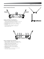
Receiver Controls and Functions
1a
2
3
1b
POWER
4
SYSTEM 8
RF
POWER
SYSTEM 8
RF
PEAK
Figure A — Front Panel Controls and Functions
1. ANTENNAS: Position the “signal” antenna (1a) and
“ground” antenna (1b) as shown to the right and above right. Fully
extend both antennas by pulling on the endcaps.
2. RF INDICATOR: Lights to show presence of transmitter signal.
3. POWER INDICATOR: Lights when power is supplied to
the receiver.
4. AF PEAK INDICATOR: Only lights when audio distortion
is present at maximum modulation. Not affected by
position of Volume control.
1
MIN.
2
MAX.
SQUELCH
MIN.
POWER
SYSTEM 8
RF
3
4
UNBALANCED
DC 12V IN
500mA
MAX.
VOLUME
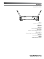
Figure B — Rear Panel Controls and Functions
1. SQUELCH CONTROL: Adjusts level of noise-muting circuit
(preset at factory but can be adjusted as circumstances warrant).
2. VOLUME CONTROL: Adjusts the audio level at the 1/4"
output jack. Does not affect AF Peak indicator.
3. AUDIO OUTPUT JACK: 1/4" TS (Tip-Sleeve) or “mono”
phone jack. Use a shielded cable to connect to an
unbalanced aux-level input of a mixer or amplifier.
4. POWER INPUT JACK: Connect the DC plug from the
included AC adapter.
5. CORD HOOK: Loop the cord around the cord hook to keep
the DC plug from pulling out accidentally.
5
PEAK
PEAK