Download Modular Protection System for Motors User Manual

Transcript
User Manual
Modular Protection System for Motors
Catalog Number 825-P
Important User Information
Because of the variety of uses for the products described in this publication, those responsible for the application and use of
this control equipment must satisfy themselves that all necessary steps have been taken to assure that each application and
use meets all performance and safety requirements, including any applicable laws, regulations, codes and standards.
The illustrations, charts, sample programs and layout examples shown in this guide are intended solely for purposes of
example. Since there are many variables and requirements associated with any particular installation, Rockwell Automation
does not assume responsibility or liability (to include intellectual property liability) for actual use based upon the examples
shown in this publication.
Rockwell Automation publication SGI-1.1, Safety Guidelines for the Application, Installation and Maintenance of SolidState Control (available from your local Allen-Bradley distributor), describes some important differences between solidstate equipment and electromechanical devices that should be taken into consideration when applying products such as
those described in this publication.
Reproduction of the contents of this copyrighted publication, in whole or part, without written permission of
Rockwell Automation, is prohibited.
Throughout this manual we use notes to make you aware of safety considerations:
WARNING: Identifies information about practices or circumstances that can cause an explosion in a hazardous environment,
which may lead to personal injury or death, property damage, or economic loss.
ATTENTION: Identifies information about practices or circumstances that can lead to personal injury or death, property
damage, or economic loss. Attentions help you identify a hazard, avoid a hazard, and recognize the consequence.
SHOCK HAZARD: Labels may be on or inside the equipment, for example, a drive or motor, to alert people that dangerous
voltage may be present.
BURN HAZARD: Labels may be on or inside the equipment, for example, a drive or motor, to alert people that surfaces may
reach dangerous temperatures.
IMPORTANT
Identifies information that is critical for successful application and understanding of the product.
DeviceNet and the DeviceNet logo are trademarks of the Open Device Vendors Association (ODVA).
Microsoft Windows is a registered trademark of the Microsoft Corporation.
European Communities (EC)
Directive Compliance
If this product has the CE mark it is approved for installation within the European Union and European Economic Area
(EEA). It has been designed and tested to meet the following directives.
EMC Directives
This product is tested to meet the Council Directive 89/336/EEC Electromagnetic Compatibility (EMC) by applying the
following standards, in whole:
• EN 60947-4-1 — Low-Voltage Switchgear and Controlgear: Part 4: Contactors and Motor Starters - Section 1:
Electromechanical Contactors and Motor Starters
• EN 60947-5-1 — Low-Voltage Switchgear and Controlgear: Part 5: Control Circuit Devices and Switching Elements Section 1: Electromechanical Control Circuit Devices
This product is intended for use in an industrial environment.
Low Voltage Directive
This product is tested to meet Council Directive 73/23/EEC Low Voltage as amended by 93/68/EEC by applying the
safety requirements of EN 60947-4-1 and EN 60947-5-1. For specific information required by EN 60947-4-1 and EN
60947-5-1, see the appropriate sections in this publication.
Notice
This product has been designed for environment A. Use of this product in environment B can cause unwanted
elctromagnetic disturbances in which case the user could be required to take adequate mitigation measures.
Rockwell Automation Publication 825-UM004D-EN-P - November 2012
3
4
Rockwell Automation Publication 825-UM004D-EN-P - November
Table of Contents
Important User Information . . . . . . . . . . . . . . . . . . . . . . . . . . . . . . . . . . . . . . .
European Communities (EC) Directive Compliance . . . . . . . . . . . . . . . . .
EMC Directives . . . . . . . . . . . . . . . . . . . . . . . . . . . . . . . . . . . . . . . . . . . . . . . . . . .
Low Voltage Directive . . . . . . . . . . . . . . . . . . . . . . . . . . . . . . . . . . . . . . . . . . . . .
Preface
2
3
3
3
Manual Overview . . . . . . . . . . . . . . . . . . . . . . . . . . . . . . . . . . . . . . . . . . . . . . . . 11
Conventions . . . . . . . . . . . . . . . . . . . . . . . . . . . . . . . . . . . . . . . . . . . . . . . . . . . . . 12
Chapter 1
Introduction
Overview . . . . . . . . . . . . . . . . . . . . . . . . . . . . . . . . . . . . . . . . . . . . . . . . . . . . . . . .
Features . . . . . . . . . . . . . . . . . . . . . . . . . . . . . . . . . . . . . . . . . . . . . . . . . . . . . . . . .
Options and Accessories . . . . . . . . . . . . . . . . . . . . . . . . . . . . . . . . . . . . . . . . . .
Applications . . . . . . . . . . . . . . . . . . . . . . . . . . . . . . . . . . . . . . . . . . . . . . . . . . . . .
13
13
14
15
Chapter 2
Installation
Relay Placement. . . . . . . . . . . . . . . . . . . . . . . . . . . . . . . . . . . . . . . . . . . . . . . . . .
Physical Location . . . . . . . . . . . . . . . . . . . . . . . . . . . . . . . . . . . . . . . . . . . . .
Relay Mounting . . . . . . . . . . . . . . . . . . . . . . . . . . . . . . . . . . . . . . . . . . . . . .
Rear-Panel Connections . . . . . . . . . . . . . . . . . . . . . . . . . . . . . . . . . . . . . . . . . .
Rear-Panel Diagram . . . . . . . . . . . . . . . . . . . . . . . . . . . . . . . . . . . . . . . . . .
Top-Panel Diagram . . . . . . . . . . . . . . . . . . . . . . . . . . . . . . . . . . . . . . . . . . .
Power Connections . . . . . . . . . . . . . . . . . . . . . . . . . . . . . . . . . . . . . . . . . . .
I/O Diagram . . . . . . . . . . . . . . . . . . . . . . . . . . . . . . . . . . . . . . . . . . . . . . . . .
AC/Control Connection Diagrams. . . . . . . . . . . . . . . . . . . . . . . . . . . . . . . .
Fail-Safe/Non-Fail-Safe Tripping . . . . . . . . . . . . . . . . . . . . . . . . . . . . . .
Converter Module Connection . . . . . . . . . . . . . . . . . . . . . . . . . . . . . . . .
Core Balance Current Transformer Connections . . . . . . . . . . . . . . .
Voltage Connections. . . . . . . . . . . . . . . . . . . . . . . . . . . . . . . . . . . . . . . . . .
Full-Voltage Non-Reversing Starter . . . . . . . . . . . . . . . . . . . . . . . . . . . .
Full-Voltage Reversing Starter . . . . . . . . . . . . . . . . . . . . . . . . . . . . . . . . .
Star-Delta Starting. . . . . . . . . . . . . . . . . . . . . . . . . . . . . . . . . . . . . . . . . . . .
Two-Speed Motor . . . . . . . . . . . . . . . . . . . . . . . . . . . . . . . . . . . . . . . . . . . .
Field Serviceability . . . . . . . . . . . . . . . . . . . . . . . . . . . . . . . . . . . . . . . . . . . . . . .
Fuse Replacement . . . . . . . . . . . . . . . . . . . . . . . . . . . . . . . . . . . . . . . . . . . .
Real-Time Clock Battery Replacement . . . . . . . . . . . . . . . . . . . . . . . . .
17
17
17
18
18
19
19
20
21
21
23
24
25
26
28
28
30
31
32
32
Chapter 3
Front Panel Operation
Front Panel Layout . . . . . . . . . . . . . . . . . . . . . . . . . . . . . . . . . . . . . . . . . . . . . . .
Normal Front Panel Display. . . . . . . . . . . . . . . . . . . . . . . . . . . . . . . . . . . . . . .
Front Panel Automatic Messages . . . . . . . . . . . . . . . . . . . . . . . . . . . . . . . . . .
Front Panel Menus and Operations . . . . . . . . . . . . . . . . . . . . . . . . . . . . . . . .
Front Panel Security . . . . . . . . . . . . . . . . . . . . . . . . . . . . . . . . . . . . . . . . . .
Front Panel Main Menu . . . . . . . . . . . . . . . . . . . . . . . . . . . . . . . . . . . . . . . . . .
View or Change Settings Using the Front Panel . . . . . . . . . . . . . . . . . . . . .
Setting Entry Error Messages . . . . . . . . . . . . . . . . . . . . . . . . . . . . . . . . . . . . . .
Rockwell Automation Publication 825-UM004D-EN-P – November 2012
33
33
34
35
37
40
41
43
5
Table of Contents
Chapter 4
Hardware Commissioning
Connecting a Converter Module (MCM) . . . . . . . . . . . . . . . . . . . . . . . . . .
Adding an Optional I/O Card . . . . . . . . . . . . . . . . . . . . . . . . . . . . . . . . . . . .
Adding the Optional
Voltage Card. . . . . . . . . . . . . . . . . . . . . . . . . . . . . . . . . . . . . . . . . . . . . . . . . . . . .
Adding the Optional Communication Card. . . . . . . . . . . . . . . . . . . . . . . .
Removing an Option Card . . . . . . . . . . . . . . . . . . . . . . . . . . . . . . . . . . . . . . . .
45
47
48
49
50
Chapter 5
Using MPS Explorer
Software Overview . . . . . . . . . . . . . . . . . . . . . . . . . . . . . . . . . . . . . . . . . . . . . . .
Communications Settings. . . . . . . . . . . . . . . . . . . . . . . . . . . . . . . . . . . . . . . . .
Connection/Access Level . . . . . . . . . . . . . . . . . . . . . . . . . . . . . . . . . . . . . . . . .
Data Management. . . . . . . . . . . . . . . . . . . . . . . . . . . . . . . . . . . . . . . . . . . . . . . .
Save/Open
Configuration Files. . . . . . . . . . . . . . . . . . . . . . . . . . . . . . . . . . . . . . . . . . . . . . .
Button Summary . . . . . . . . . . . . . . . . . . . . . . . . . . . . . . . . . . . . . . . . . . . . . . . . .
ANA (Test Analog Output). . . . . . . . . . . . . . . . . . . . . . . . . . . . . . . . . . .
MOT (Motor Operating Statistics) . . . . . . . . . . . . . . . . . . . . . . . . . . . .
SER (Serialized Events Recording) . . . . . . . . . . . . . . . . . . . . . . . . . . . . .
STA (Relay Status) . . . . . . . . . . . . . . . . . . . . . . . . . . . . . . . . . . . . . . . . . . .
SUM (Events Summary Report) . . . . . . . . . . . . . . . . . . . . . . . . . . . . . . .
MET (Instantaneous Metering)
RTD (RTD/Thermal Metering). . . . . . . . . . . . . . . . . . . . . . . . . . . . . . .
TAR (Display Target Words) . . . . . . . . . . . . . . . . . . . . . . . . . . . . . . . . .
Data Visualization/Trending. . . . . . . . . . . . . . . . . . . . . . . . . . . . . . . . . . . . . .
Validate Settings . . . . . . . . . . . . . . . . . . . . . . . . . . . . . . . . . . . . . . . . . . . . . . . . .
I/O Mapping . . . . . . . . . . . . . . . . . . . . . . . . . . . . . . . . . . . . . . . . . . . . . . . . . . . .
Resetting/Restoring . . . . . . . . . . . . . . . . . . . . . . . . . . . . . . . . . . . . . . . . . . . . . .
Troubleshooting . . . . . . . . . . . . . . . . . . . . . . . . . . . . . . . . . . . . . . . . . . . . . . . . .
51
51
52
52
53
53
54
54
55
55
56
57
58
59
61
62
63
63
Chapter 6
Configuring Protection & Logic Overview . . . . . . . . . . . . . . . . . . . . . . . . . . . . . . . . . . . . . . . . . . . . . . . . . . . . . . . . 65
Application Data. . . . . . . . . . . . . . . . . . . . . . . . . . . . . . . . . . . . . . . . . . . . . . . . . 66
Functions
Main Settings . . . . . . . . . . . . . . . . . . . . . . . . . . . . . . . . . . . . . . . . . . . . . . . . . . . .
Identifier Settings . . . . . . . . . . . . . . . . . . . . . . . . . . . . . . . . . . . . . . . . . . . .
Phase Rotation, Nominal Frequency Settings . . . . . . . . . . . . . . . . . . .
Date Format . . . . . . . . . . . . . . . . . . . . . . . . . . . . . . . . . . . . . . . . . . . . . . . . .
Current Transformer (CT) Configuration, Full Load Current
Settings . . . . . . . . . . . . . . . . . . . . . . . . . . . . . . . . . . . . . . . . . . . . . . . . . . . . . .
Voltage Transformer (VT) Configuration Settings . . . . . . . . . . . . . .
Basic Motor Protection . . . . . . . . . . . . . . . . . . . . . . . . . . . . . . . . . . . . . . . . . . .
Overload (Thermal Model) . . . . . . . . . . . . . . . . . . . . . . . . . . . . . . . . . . .
Short Circuit. . . . . . . . . . . . . . . . . . . . . . . . . . . . . . . . . . . . . . . . . . . . . . . . .
Ground Fault . . . . . . . . . . . . . . . . . . . . . . . . . . . . . . . . . . . . . . . . . . . . . . . . . . . .
Jam . . . . . . . . . . . . . . . . . . . . . . . . . . . . . . . . . . . . . . . . . . . . . . . . . . . . . . . . . . . . .
Undercurrent (Load Loss) . . . . . . . . . . . . . . . . . . . . . . . . . . . . . . . . . . . . . . . .
6
Rockwell Automation Publication 825-UM004D-EN-P - November 2012
66
66
67
67
68
69
69
70
74
75
77
77
Table of Contents
Current Imbalance/
Phase Loss . . . . . . . . . . . . . . . . . . . . . . . . . . . . . . . . . . . . . . . . . . . . . . . . . . . . . . . 78
Protection Disable . . . . . . . . . . . . . . . . . . . . . . . . . . . . . . . . . . . . . . . . . . . . . . . 79
Start Monitoring . . . . . . . . . . . . . . . . . . . . . . . . . . . . . . . . . . . . . . . . . . . . . . . . . 79
Star-Delta (Wye-Delta) Starting. . . . . . . . . . . . . . . . . . . . . . . . . . . . . . . . . . . 80
Start Inhibit . . . . . . . . . . . . . . . . . . . . . . . . . . . . . . . . . . . . . . . . . . . . . . . . . . . . . 81
Phase Reversal Protection . . . . . . . . . . . . . . . . . . . . . . . . . . . . . . . . . . . . . . . . . 81
Speed Switch (Stalling
During Start) . . . . . . . . . . . . . . . . . . . . . . . . . . . . . . . . . . . . . . . . . . . . . . . . . . . . 82
Thermistor (PTC) Monitoring. . . . . . . . . . . . . . . . . . . . . . . . . . . . . . . . . . . . 82
RTD-Based Protection . . . . . . . . . . . . . . . . . . . . . . . . . . . . . . . . . . . . . . . . . . . 83
Voltage-Based Protection . . . . . . . . . . . . . . . . . . . . . . . . . . . . . . . . . . . . . . . . . 86
Undervoltage. . . . . . . . . . . . . . . . . . . . . . . . . . . . . . . . . . . . . . . . . . . . . . . . . 86
Overvoltage . . . . . . . . . . . . . . . . . . . . . . . . . . . . . . . . . . . . . . . . . . . . . . . . . . 87
VAR Function . . . . . . . . . . . . . . . . . . . . . . . . . . . . . . . . . . . . . . . . . . . . . . . 87
Underpower . . . . . . . . . . . . . . . . . . . . . . . . . . . . . . . . . . . . . . . . . . . . . . . . . 88
Power Factor . . . . . . . . . . . . . . . . . . . . . . . . . . . . . . . . . . . . . . . . . . . . . . . . . 88
Frequency. . . . . . . . . . . . . . . . . . . . . . . . . . . . . . . . . . . . . . . . . . . . . . . . . . . . 89
Load Control Function . . . . . . . . . . . . . . . . . . . . . . . . . . . . . . . . . . . . . . . 89
I/O Configuration . . . . . . . . . . . . . . . . . . . . . . . . . . . . . . . . . . . . . . . . . . . . . . . 90
Analog Output . . . . . . . . . . . . . . . . . . . . . . . . . . . . . . . . . . . . . . . . . . . . . . . 90
Trip Inhibit (Block) . . . . . . . . . . . . . . . . . . . . . . . . . . . . . . . . . . . . . . . . . . 91
Output Relay Behavior. . . . . . . . . . . . . . . . . . . . . . . . . . . . . . . . . . . . . . . . 92
Timer Function . . . . . . . . . . . . . . . . . . . . . . . . . . . . . . . . . . . . . . . . . . . . . . 93
Front Panel Settings . . . . . . . . . . . . . . . . . . . . . . . . . . . . . . . . . . . . . . . . . . 93
Display Enable . . . . . . . . . . . . . . . . . . . . . . . . . . . . . . . . . . . . . . . . . . . . . . . 94
I/O Assignments . . . . . . . . . . . . . . . . . . . . . . . . . . . . . . . . . . . . . . . . . . . . . 95
Logic Explanation . . . . . . . . . . . . . . . . . . . . . . . . . . . . . . . . . . . . . . . . . . . . . . . 100
Stop/Trip Logic . . . . . . . . . . . . . . . . . . . . . . . . . . . . . . . . . . . . . . . . . . . . . 100
Initiate Trip. . . . . . . . . . . . . . . . . . . . . . . . . . . . . . . . . . . . . . . . . . . . . . . . . 100
Unlatch Trip. . . . . . . . . . . . . . . . . . . . . . . . . . . . . . . . . . . . . . . . . . . . . . . . 100
Start & Emergency Restart Logic. . . . . . . . . . . . . . . . . . . . . . . . . . . . . . 101
Overload Curves . . . . . . . . . . . . . . . . . . . . . . . . . . . . . . . . . . . . . . . . . . . . 103
Chapter 7
Metering & Monitoring
Overview . . . . . . . . . . . . . . . . . . . . . . . . . . . . . . . . . . . . . . . . . . . . . . . . . . . . . . .
Metering . . . . . . . . . . . . . . . . . . . . . . . . . . . . . . . . . . . . . . . . . . . . . . . . . . . . . . .
Instantaneous Metering . . . . . . . . . . . . . . . . . . . . . . . . . . . . . . . . . . . . . .
Thermal Metering . . . . . . . . . . . . . . . . . . . . . . . . . . . . . . . . . . . . . . . . . . .
Power Measurement Conventions . . . . . . . . . . . . . . . . . . . . . . . . . . . . . . . .
Motor Operating Statistics . . . . . . . . . . . . . . . . . . . . . . . . . . . . . . . . . . . . . . .
105
105
106
106
107
108
Chapter 8
Analyzing Events
Overview . . . . . . . . . . . . . . . . . . . . . . . . . . . . . . . . . . . . . . . . . . . . . . . . . . . . . . . 109
Event Summary Reports . . . . . . . . . . . . . . . . . . . . . . . . . . . . . . . . . . . . . . . . . 109
Serialized Events Recording (SER) Report. . . . . . . . . . . . . . . . . . . . . . . . . 110
Rockwell Automation Publication 825-UM004D-EN-P - November 2012
7
Table of Contents
SER Triggering . . . . . . . . . . . . . . . . . . . . . . . . . . . . . . . . . . . . . . . . . . . . . . 110
Example Reports . . . . . . . . . . . . . . . . . . . . . . . . . . . . . . . . . . . . . . . . . . . . . . . . 111
Chapter 9
825-PDN DeviceNet
Communication Card
Introduction . . . . . . . . . . . . . . . . . . . . . . . . . . . . . . . . . . . . . . . . . . . . . . . . . . . .
Features . . . . . . . . . . . . . . . . . . . . . . . . . . . . . . . . . . . . . . . . . . . . . . . . . . . . . . . .
Required Equipment . . . . . . . . . . . . . . . . . . . . . . . . . . . . . . . . . . . . . . . . . . . .
Equipment Shipping with the Card . . . . . . . . . . . . . . . . . . . . . . . . . . .
User-Supplied Equipment. . . . . . . . . . . . . . . . . . . . . . . . . . . . . . . . . . . .
Wiring . . . . . . . . . . . . . . . . . . . . . . . . . . . . . . . . . . . . . . . . . . . . . . . . . . . . . . . . .
Node Commissioning . . . . . . . . . . . . . . . . . . . . . . . . . . . . . . . . . . . . . . . . . . .
Setting the Hardware Switches . . . . . . . . . . . . . . . . . . . . . . . . . . . . . . .
Using RSNetWorx for DeviceNet . . . . . . . . . . . . . . . . . . . . . . . . . . . .
Explicit Messaging. . . . . . . . . . . . . . . . . . . . . . . . . . . . . . . . . . . . . . . . . . . . . . .
Setting Up the MSG instruction . . . . . . . . . . . . . . . . . . . . . . . . . . . . . .
DeviceLogix . . . . . . . . . . . . . . . . . . . . . . . . . . . . . . . . . . . . . . . . . . . . . . . . . . . .
DeviceLogix Programming Example. . . . . . . . . . . . . . . . . . . . . . . . . . .
Parameter Groups . . . . . . . . . . . . . . . . . . . . . . . . . . . . . . . . . . . . . . . . . . . . . . .
113
115
116
116
116
116
117
118
119
121
122
124
125
129
Chapter 10
Modbus RTU Communications
Overview . . . . . . . . . . . . . . . . . . . . . . . . . . . . . . . . . . . . . . . . . . . . . . . . . . . . . . .
Installation . . . . . . . . . . . . . . . . . . . . . . . . . . . . . . . . . . . . . . . . . . . . . . . . . . . . .
Mounting. . . . . . . . . . . . . . . . . . . . . . . . . . . . . . . . . . . . . . . . . . . . . . . . . . .
Wiring . . . . . . . . . . . . . . . . . . . . . . . . . . . . . . . . . . . . . . . . . . . . . . . . . . . . .
Commissioning . . . . . . . . . . . . . . . . . . . . . . . . . . . . . . . . . . . . . . . . . . . . . . . . .
Modbus Queries . . . . . . . . . . . . . . . . . . . . . . . . . . . . . . . . . . . . . . . . . . . . . . . .
Modbus Responses . . . . . . . . . . . . . . . . . . . . . . . . . . . . . . . . . . . . . . . . . . . . . .
Supported Modbus Function Codes . . . . . . . . . . . . . . . . . . . . . . . . . . . . . .
Modbus Exception Responses . . . . . . . . . . . . . . . . . . . . . . . . . . . . . . . . . . . .
Cyclical Redundancy Check. . . . . . . . . . . . . . . . . . . . . . . . . . . . . . . . . . . . . .
03h Read Holding Register Command . . . . . . . . . . . . . . . . . . . . . . . . . . . .
06h Preset Single Register Command . . . . . . . . . . . . . . . . . . . . . . . . . . . . .
10h Preset Multiple Registers Command . . . . . . . . . . . . . . . . . . . . . . . . . .
60h Read Parameter Information Command . . . . . . . . . . . . . . . . . . . . . .
61h Read Parameter Text Command . . . . . . . . . . . . . . . . . . . . . . . . . . . . .
62h Read Enumeration Text Command . . . . . . . . . . . . . . . . . . . . . . . . . .
7Dh Encapsulated Packet With Control Command . . . . . . . . . . . . . . .
7Eh NOP Command . . . . . . . . . . . . . . . . . . . . . . . . . . . . . . . . . . . . . . . . . . . .
Modbus Password Control and Parameter Modification. . . . . . . . . . . .
Modbus Serialized Events Recording Register Operation . . . . . . . . . . .
Modbus Load Profile Register Operation. . . . . . . . . . . . . . . . . . . . . . . . . .
131
131
131
132
134
135
135
135
136
136
136
137
138
139
141
142
143
144
144
145
145
Chapter 11
Testing & Troubleshooting
8
Overview . . . . . . . . . . . . . . . . . . . . . . . . . . . . . . . . . . . . . . . . . . . . . . . . . . . . . . . 147
Testing . . . . . . . . . . . . . . . . . . . . . . . . . . . . . . . . . . . . . . . . . . . . . . . . . . . . . . . . . 147
Commissioning Tests . . . . . . . . . . . . . . . . . . . . . . . . . . . . . . . . . . . . . . . . 147
Rockwell Automation Publication 825-UM004D-EN-P - November 2012
Table of Contents
Selected Functional Tests . . . . . . . . . . . . . . . . . . . . . . . . . . . . . . . . . . . .
Periodic Tests (Routine Maintenance) . . . . . . . . . . . . . . . . . . . . . . . .
Troubleshooting . . . . . . . . . . . . . . . . . . . . . . . . . . . . . . . . . . . . . . . . . . . . . . . .
Field Serviceability . . . . . . . . . . . . . . . . . . . . . . . . . . . . . . . . . . . . . . . . . . . . . .
Power Supply Fuse Replacement . . . . . . . . . . . . . . . . . . . . . . . . . . . . . .
Real-Time Clock (RTC) Battery Replacement . . . . . . . . . . . . . . . . .
Troubleshooting DeviceNet. . . . . . . . . . . . . . . . . . . . . . . . . . . . . . . . . . . . . .
Troubleshooting Device Backplane Communication . . . . . . . . . . . . . . .
151
155
157
158
158
159
160
160
Chapter 12
ASCII Serial Communications
Overview . . . . . . . . . . . . . . . . . . . . . . . . . . . . . . . . . . . . . . . . . . . . . . . . . . . . . . .
ASCII Serial Port Operation . . . . . . . . . . . . . . . . . . . . . . . . . . . . . . . . . . . . .
Introduction . . . . . . . . . . . . . . . . . . . . . . . . . . . . . . . . . . . . . . . . . . . . . . . .
Required Equipment. . . . . . . . . . . . . . . . . . . . . . . . . . . . . . . . . . . . . . . . .
Connect Your PC to the Relay . . . . . . . . . . . . . . . . . . . . . . . . . . . . . . .
Configure Your Terminal Emulation Software . . . . . . . . . . . . . . . .
Serial Port Settings . . . . . . . . . . . . . . . . . . . . . . . . . . . . . . . . . . . . . . . . . . . . . .
Using Terminal Commands . . . . . . . . . . . . . . . . . . . . . . . . . . . . . . . . . .
Serial Port Access Levels. . . . . . . . . . . . . . . . . . . . . . . . . . . . . . . . . . . . . .
Command Summary. . . . . . . . . . . . . . . . . . . . . . . . . . . . . . . . . . . . . . . . .
Description of Commands . . . . . . . . . . . . . . . . . . . . . . . . . . . . . . . . . . . . . . .
ACC and 2AC (Level 1 or 2) . . . . . . . . . . . . . . . . . . . . . . . . . . . . . . . . .
ANALOG (Level 2). . . . . . . . . . . . . . . . . . . . . . . . . . . . . . . . . . . . . . . . .
DATE (Level 1 or 2). . . . . . . . . . . . . . . . . . . . . . . . . . . . . . . . . . . . . . . . .
METER (Level 1 or 2) . . . . . . . . . . . . . . . . . . . . . . . . . . . . . . . . . . . . . . .
MOTOR (Level 1 or 2) . . . . . . . . . . . . . . . . . . . . . . . . . . . . . . . . . . . . . .
PASSWORD (Level 1 or 2) . . . . . . . . . . . . . . . . . . . . . . . . . . . . . .
QUIT (Level 1 or 2) . . . . . . . . . . . . . . . . . . . . . . . . . . . . . . . . . . . . . . . . .
SER (Level 1 or 2) . . . . . . . . . . . . . . . . . . . . . . . . . . . . . . . . . . . . . . . . . . .
SET (Level 2) . . . . . . . . . . . . . . . . . . . . . . . . . . . . . . . . . . . . . . . . . . . . . . .
SHOW . . . . . . . . . . . . . . . . . . . . . . . . . . . . . . . . . . . . . . . . . . . . . . . . . . . . .
STATUS (Level 1 or 2) . . . . . . . . . . . . . . . . . . . . . . . . . . . . . . . . . . . . . .
STOP (Level 2) . . . . . . . . . . . . . . . . . . . . . . . . . . . . . . . . . . . . . . . . . . . . .
STR (Level 2) . . . . . . . . . . . . . . . . . . . . . . . . . . . . . . . . . . . . . . . . . . . . . . .
SUMMARY (Level 1 or 2) . . . . . . . . . . . . . . . . . . . . . . . . . . . . . . . . . . .
TARGET (Level 1 or 2). . . . . . . . . . . . . . . . . . . . . . . . . . . . . . . . . . . . . .
TIME (Level 1 or 2) . . . . . . . . . . . . . . . . . . . . . . . . . . . . . . . . . . . . . . . . .
View or Change Settings with Front Panel Serial Port . . . . . . . . . . . . . .
161
161
161
161
162
163
163
164
165
166
167
167
167
167
168
170
170
171
171
172
173
174
177
177
177
178
179
179
Chapter 13
Firmware Upgrade Instructions Overview . . . . . . . . . . . . . . . . . . . . . . . . . . . . . . . . . . . . . . . . . . . . . . . . . . . . . . . 183
Required Equipment. . . . . . . . . . . . . . . . . . . . . . . . . . . . . . . . . . . . . . . . . 183
Upgrade Instructions . . . . . . . . . . . . . . . . . . . . . . . . . . . . . . . . . . . . . . . . 183
Appendix A
Specifications
Electrical Ratings. . . . . . . . . . . . . . . . . . . . . . . . . . . . . . . . . . . . . . . . . . . . . . . . 187
Rockwell Automation Publication 825-UM004D-EN-P - November 2012
9
Table of Contents
Main Circuits . . . . . . . . . . . . . . . . . . . . . . . . . . . . . . . . . . . . . . . . . . . . . . .
Control Circuits . . . . . . . . . . . . . . . . . . . . . . . . . . . . . . . . . . . . . . . . . . . .
Mechanical Ratings. . . . . . . . . . . . . . . . . . . . . . . . . . . . . . . . . . . . . . . . . . . . . .
RTD Scanner Module . . . . . . . . . . . . . . . . . . . . . . . . . . . . . . . . . . . . . . . . . . .
Electromagnetic Compatibility . . . . . . . . . . . . . . . . . . . . . . . . . . . . . . . . . . .
Metering Accuracy . . . . . . . . . . . . . . . . . . . . . . . . . . . . . . . . . . . . . . . . . . . . . .
Standards. . . . . . . . . . . . . . . . . . . . . . . . . . . . . . . . . . . . . . . . . . . . . . . . . . . . . . .
Processing . . . . . . . . . . . . . . . . . . . . . . . . . . . . . . . . . . . . . . . . . . . . . . . . . . . . . .
Primary Current Transformers . . . . . . . . . . . . . . . . . . . . . . . . . . . . . . . . . . .
825-CBCT Core Balance Current Transformer . . . . . . . . . . . . . . . . . . .
DeviceNet Communication Card . . . . . . . . . . . . . . . . . . . . . . . . . . . . . . . .
187
188
189
189
190
190
190
190
191
191
192
Appendix B
Parameter List
Overview . . . . . . . . . . . . . . . . . . . . . . . . . . . . . . . . . . . . . . . . . . . . . . . . . . . . . . . 193
Appendix C
Relay Word Bits
Overview . . . . . . . . . . . . . . . . . . . . . . . . . . . . . . . . . . . . . . . . . . . . . . . . . . . . . . . 235
Definitions . . . . . . . . . . . . . . . . . . . . . . . . . . . . . . . . . . . . . . . . . . . . . . . . . . . . . 235
Appendix D
ASCII Port Relay Command
Summary
ASCII Port Relay . . . . . . . . . . . . . . . . . . . . . . . . . . . . . . . . . . . . . . . . . . . . . . . 239
Appendix E
DeviceNet Information
10
Electronic Data Sheets . . . . . . . . . . . . . . . . . . . . . . . . . . . . . . . . . . . . . . . . . . .
Product Codes . . . . . . . . . . . . . . . . . . . . . . . . . . . . . . . . . . . . . . . . . . . . . . . . . .
DeviceNet Objects . . . . . . . . . . . . . . . . . . . . . . . . . . . . . . . . . . . . . . . . . . . . . .
Identity Object - CLASS CODE 0x0001. . . . . . . . . . . . . . . . . . . . . . . . . .
Message Router - CLASS CODE 0x0002 . . . . . . . . . . . . . . . . . . . . . . . . .
DeviceNet Object - CLASS CODE 0x0003 . . . . . . . . . . . . . . . . . . . . . . .
Assembly Object - CLASS CODE 0x0004 . . . . . . . . . . . . . . . . . . . . . . . .
Custom Parameter Based Input (Produced) Assembly
Instance 100 . . . . . . . . . . . . . . . . . . . . . . . . . . . . . . . . . . . . . . . . . . . . . . . . . . . .
Standard Input (Produced) Assemblies. . . . . . . . . . . . . . . . . . . . . . . . . . . .
Standard Output (Consumed) Assemblies . . . . . . . . . . . . . . . . . . . . . . . .
Connection Object - CLASS CODE 0x0005 . . . . . . . . . . . . . . . . . . . . . .
Discreet Input Point Object - CLASS CODE 0x0008. . . . . . . . . . . . . .
Discreet Output Point Object - CLASS CODE 0x0009 . . . . . . . . . . . .
Discrete Output Point Object Special Requirements . . . . . . . . . . . . . . .
Parameter Object - CLASS CODE 0x000F . . . . . . . . . . . . . . . . . . . . . . .
Parameter Object - CLASS CODE 0x0010. . . . . . . . . . . . . . . . . . . . . . . .
Discrete Output Group Object - CLASS CODE 0x001E. . . . . . . . . . .
Control Supervisor Object - CLASS CODE 0x0029 . . . . . . . . . . . . . . .
Acknowledge Handler Object - CLASS CODE 0x002b . . . . . . . . . . . .
Overload Object - CLASS CODE 0x002c. . . . . . . . . . . . . . . . . . . . . . . . .
DeviceNet Interface Object - CLASS CODE 0x00B4 . . . . . . . . . . . . . .
Rockwell Automation Publication 825-UM004D-EN-P - November 2012
242
242
242
243
244
244
245
246
247
250
251
254
255
256
257
258
259
261
261
262
262
Preface
Manual Overview
The 825-P Modular Protection System User Manual describes common aspects
of motor relay application and use. It includes the necessary information to
install, set, test, and operate the relay and more detailed information about
settings and commands. The chapter descriptions are as follows:
• Preface
Describes the manual organization and conventions used to present
information.
• Chapter 1: Introduction
Describes the basic features and functions of the 825-P.
• Chapter 2: Installation
Describes how to mount and wire the 825-P; illustrates wiring connections
for various applications.
• Chapter 3: Front Panel Operation
Explains features and use of the front panel, including front-panel
command menu, default displays, and automatic messages.
• Chapter 4: Hardware Commissioning
Describes how to install and commission the various hardware options for
the 825-P.
• Chapter 5: Using MPS Explorer
Describes how to use MPS Explorer software to read diagnostic
information and configure the 825-P.
• Chapter 6: Configuring Protection & Logic Functions
Describes the operating characteristic of each protection element and
explains how to calculate their settings; describes contact output logic.
• Chapter 7: Metering & Monitoring
Describes the operation of each metering function; describes the
monitoring functions.
• Chapter 8: Analyzing Events
Describes front-panel LED operation, trip-type front-panel messages,
event summary data, standard event reports, and Serialized Events
Recording (SER) report.
• Chapter 9: 825-PDN DeviceNet Communication Card
Describes the communication features supported by the 825-P DeviceNet
option card.
• Chapter 10: Modbus RTU Communications
This chapter describes the communications features supported by the 825P Modbus RTU Option Card.
• Chapter 11: Testing & Troubleshooting
Describes protection element test procedures, relay self-test, and relay
troubleshooting.
• Chapter 12: ASCII Serial Communications
Describes the serial port commands supported by the 825-P.
• Chapter 13: Firmware Upgrade Instructions
Describes the process to upgrade the firmware for the 825-P.
Rockwell Automation Publication 825-UM004D-EN-P - November 2012
11
Preface
• Appendix A: Specifications
Provides detailed specification and certification information for all
components of the 825-P Modular Protection System.
• Appendix B: Parameter List
Describes the available parameters for the 825-P.
• Appendix C: Relay Word Bits
Lists and describes the Relay Word bits (e.g., real-time status of relay I/O,
protection functions).
• Appendix D: ASCII Port Relay Command Summary
Briefly describes the serial port commands that are fully described in
Chapter 12: ASCII Serial Communications.
• Appendix E: DeviceNet Information
Describes the details of the features supported by the 825-P DeviceNet
option card.
Conventions
Typographic Conventions
The primary ways to configure the 825-P are by using:
• MPS Explorer configuration and monitoring software.
• a command line interface on a PC terminal emulation window, such as
Microsoft® HyperTerminal.
• the front-panel menus and push buttons.
Examples
This instruction manual uses several example illustrations and instructions
to explain how to effectively operate the 825-P. These examples are for
demonstration purposes only. The firmware identification information or
settings values included in these examples may not necessarily match those
in the current version of your 825-P.
Example Description
STATUS Commands typed at a command line interface on a PC.
Enter Single keystroke on a PC keyboard.
Ctrl+D Multiple/combination keystroke on a PC keyboard.
Start > Settings PC dialog boxes and menu selections.
The “>” character indicates submenus.
CLOSE Relay front-panel push buttons.
ENABLE Relay front-panel or rear-panel labels.
MAIN > METER Relay front-panel LCD menus and relay responses.
The “>” character indicates submenus.
12
Rockwell Automation Publication 825-UM004D-EN-P - November 2012
Chapter
1
Introduction
Overview
The 825-P Motor Relay is designed to protect three-phase motors. The basic
relay provides locked rotor, overload, unbalance, and short circuit protection.
Voltage-based and RTD-based protection is available as an option. All relay
models provide monitoring functions.
This manual contains the information for installing, setting, testing, operating,
and maintaining an 825-P. It is not necessary to review the entire manual to
perform specific tasks.
A Quick Start Guide, Publication 825-QS001, is also available. It will help to step
the first-time user through the device commissioning process.
Features
Standard Protection Features
•
•
•
•
•
•
•
•
•
Thermal Overload (thermal model)
PTC (positive temperature coefficient) Overtemperature
Undercurrent (Load Loss)
Current Imbalance and Phase Loss
Overcurrent (Load Jam)
Short Circuit
Ground Fault (Residual)
Ground Fault (Zero Sequence)
Motor Starting/Running
– Protection Inhibit During Start
– Start Motor Timer
– Notching or Jogging Device
– TCU (Thermal Capacity Utilization) Start Inhibit
– Anti-Backspin Timer
– Emergency Start
– Two Speed Protection
– Reduced Voltage Starting (Star-Delta)
– Stall-Speed Switch
• Frequency
Rockwell Automation Publication 825-UM004D-EN-P - November 2012
13
Chapter 1
Introduction
Optional Protection Features
Voltage-Based Protection
•
•
•
•
•
•
Undervoltage
Overvoltage
Underpower
Reactive Overpower
Phase Reversal
Power Factor
RTD-Based Protection
Up to 12 RTDs can be monitored when an external 825-PR12D RTD Scanner is
used. There are separate trip and warn settings for each RTD.
Monitoring Features
The monitoring features of the 825-P are as follows:
• Event summaries contain relay ID, date and time, trip cause, and current/
voltage magnitudes.
• Serialized Events Recording (SER).
• Motor running time since the last reset.
• Start cycles since the last reset.
• Emergency start cycles since the last reset.
• A complete suite of accurate metering functions.
Options and Accessories
Options
• The 825-P has the following options:
– Voltage Option: four-wire wye or open-delta connected potential
transformers
– Input/Output (I/O) Option: one 4…20 mA analog (transducer)
output, three additional control inputs, and four additional contact
outputs
– Network communications options
• DeviceNet
• Modbus
14
Rockwell Automation Publication 825-UM004D-EN-P - November 2012
Introduction
Chapter 1
Accessories
Phase current inputs require one of the following external 825-MCM
converter modules:
Table 1 - Converter Module List
Description
Cat. No.
0.5…2.5 A Converter Module
825-MCM2
1.0…5.0 A Converter Module
825-MCM5
2.5…20 A Converter Module
825-MCM20
20…180 A Converter Module
825-MCM180
160…630 A Converter Module
825-MCM630
160…630 A Converter Module
825-MCM630N
The ground fault current (zero sequence) feature requires an external 825-CBCT
Core Balance Current Transformer, or equivalent.
The following devices are required to add RTD protection:
• An external RTD scanner Cat. No. 825-PR12D RTD. A fiber-optic cable
is not included with the 825-PR12D).
• A simplex 62.5/125 μm fiber-optic cable with ST connector for
connecting the external RTD scanner to the 825-P (e.g., part# 1570FCBLMM-SX-62-STST-2M from Ultra Spec Cable - http://store.ultraspec.us).
Applications
The 825-P can be used with the following across the line starter applications:
• Low and medium voltage with 2 or 3 potential transformers
• With or without phase current transformers
• With or without zero-sequence core balance current transformer
• With or without external RTD module
• Reversing starter
• Star-delta starting
• Two-speed motors
Figure 1 shows “across the line starting” AC connections for the case where
external current transformers are not required. Refer to Chapter 2: Installation
for additional applications and the related connection diagrams.
Rockwell Automation Publication 825-UM004D-EN-P - November 2012
15
Chapter 1
Introduction
Figure 1 - AC Connections Without CTs
L1
L2
L3
3
5
Converter Module
Cat. No. 825-MCM2
Cat. No. 825-MCM5
Cat. No. 825-MCM20
Cat. No. 825-MCM180
Cat. No. 825-MCM420
Cat. No. 825-MCM630N
A1
A2
1
825-MCM
2
4
6
M
3~
16
Rockwell Automation Publication 825-UM004D-EN-P - November 2012
825-P
Chapter
2
Installation
Relay Placement
Proper placement of the 825-P Motor Relay helps make certain that you receive
years of trouble-free motor protection. Use the following guidelines for proper
physical installation of the 825-P.
Physical Location
You can mount the 825-P in a sheltered indoor environment (a building or an
enclosed cabinet) that does not exceed the temperature and humidity ratings
for the relay. The relay can be mounted indoors or in an outdoor (extended)
enclosure where the relay is protected against exposure to direct sunlight,
precipitation, and full wind pressure, but neither temperature nor humidity
are controlled.
Refer to Appendix:A Specifications for environmental ratings.
Relay Mounting
To flush mount the 825-P in a panel, cut a rectangular hole with the dimensions
shown in Figure 2.
Figure 2 - Relay Mounted In a Panel
18
(7. 6.0
32
)
Legend
mm
(in)
138.0
(5.43)
19
(7. 2.0
56
)
0
4. )
14 .67
(5
Mounting Panel–maximum thickness 6.5 mm
#8 x 1/2 inch mounting screw;
Torque specification = 0.9...1.3 N. m (8...12 Lb-in)
Gasket
147.4
(5.80)
20.8
(0.82)
Rockwell Automation Publication 825-UM004D-EN-P - November 2012
17
Chapter 2
Installation
Rear-Panel Connections
Rear-Panel Diagram
The physical layout of the connectors on the rear-panel of a fully configured
825-P is shown in Figure 3.
Figure 3 - Rear-Panel Layout
Factory
Configured
Factory
Configured
D
L1
33
C
A
B
0.31 in
8.0 mm
DEVICENET
34
L2
43
L3
44
N
53
A1+
BK
BU
SH
WH
RD
A2-
RTD
MODULE
24
Core Balance
Current Transformer
Y22
CBCT
Y24
S1
S2
Y26
Y2157-0138
Z
E
PGM
8
MSD
MAC ID
2
6
DATA
RATE
96
96
98
Y12
2
6
4
6
4
8
0 = 125K
1 = 250K
2 = 500K
95
98
4
8
LSD
95
Y12
Y14
AUTO
BAUD
157-0136
D
Current Voltage Input Expansion
Input
Card
I/O
18
NONFAIL-SAFE
T1
T2
BUS
STATUS
I-
23
PTC
NETWORK
STATUS
I+
14
RX
63
64
!
!
13
54
!
WIRE STRIP GUIDE
MCM / CWE
E
190-3011-01
Z
FAIL-SAFE
Converter
Module
Input
Ground
Screw
Rockwell Automation Publication 825-UM004D-EN-P - November 2012
C
B
Communication
Card
A
Incoming
Temperature Power
Input
Installation
Chapter 2
Top-Panel Diagram
The input and output designations for the rear-panel connectors of a fully
configured 825-P are shown in Figure 4. This diagram is located on the top panel
of the relay.
Figure 4 - Top-Panel Input and Output Designations
‡ See documentation for input voltage rating.
Power Connections
The power terminals on the rear panel (A1+ and A2-) must connect to
110…240V AC or 110…250V DC for the 825-PD and 24…48V DC for the 825PZ. For complete power input specifications, see Appendix:A Specifications.
The power terminals are isolated from the chassis ground. Use 16 AWG
(1.5 mm2) size or heavier wire to connect to the POWER terminals. Connection
to external power must comply with IEC 947-1 and IEC 947-3. Place an external
switch, circuit breaker, or overcurrent device in the power leads for the 825-P;
this device must interrupt both the positive (A1+)and neutral (A2-) power leads.
The maximum current rating for the power disconnect circuit breaker or
overcurrent device (fuse) must be 20 A. Be sure to locate this device within 3.0 m
(9.8 ft.) of the relay.
Operational power is internally fused by power supply fuse. See Field
Serviceability on page 31 for details. Be sure to use fuses that comply with
IEC 127-2.
Rockwell Automation Publication 825-UM004D-EN-P - November 2012
19
Chapter 2
Installation
I/O Diagram
A more functional representation of the control (I/O) connections are shown
in Figure 5.
Figure 5 - Control I/O Connections in Powered-Down State
110…240V AC, 24…48V DC
or 110…250 V DC
24 or 120V AC/+V DC 24V AC/+V DC
6
#5
#4
#3
#2
Analog Out
#1
+/H
Y14 Y12
95
13
23
33
PTC
43
53
63
I+
I–
T1
T2
RX
IN1
IN2
IN3
IN4
IN5
5
PS
825-P Relay
Aux1 Aux2 Aux3 Aux4 Aux5 Aux6
Alarm
Trip
7
A
4
3
A1 Y26 Y24 Y22
F/O Cable
to RTD Scanner
8
–/N
Y1–
Y2–
A2
2
98
96
14
24
34
44
54
64
BK
1
24 or 120V AC/–V DC
BU
SH
WH
RD
V – CAN_L Drain CAN_H V +
24V AC/–V DC
DeviceNet Cable
➊ See Table 44 for control function assignment to the input IN1 and IN2. Connect the appropriate external contacts (#1 and #2) to the
inputs.
➋ Inputs IN3, IN4, and IN5 are available when an optional I/O extension card is present. 825-PIOD inputs are rated 120V AC/DC. 825-PIOR
inputs are rated 24V AC/DC.
➌ See Table 42 for mapping protection elements to the Trip output. See Figure 7 and Figure 16 for typical control circuit connections.
➍ See Table 43 for mapping protection and/or control elements to the Aux outputs. Outputs Aux3 through Aux6 are available when an
optional I/O extension card is present.
➎ Analog Output is available when an optional I/O extension card is present.
➏ You can connect up to six thermistors (PTC) in series. See Table 2 for PTC cable requirements.
➐ Use up to 500 meter long Simplex 62.5/125 mm fiber-optic cable (ST/ST).
➑ Available when an optional DeviceNet Communications Protocol Card is present.
20
Rockwell Automation Publication 825-UM004D-EN-P - November 2012
Installation
Chapter 2
Table 2 shows the maximum cable lengths for the PTC connections.
Table 2 - PTC Cable Requirements
AC/Control Connection
Diagrams
Wire Size,
Twisted Pair,
AWG No.
Maximum Length
(meters) Shielded Cable
Maximum Length
(meters)
Unshielded Cable
20
200
100
18
300
100
17
400
100
16
600
100
14
1000
100
This section describes fail-safe versus non-fail-safe tripping, describes voltage
connections, and provides the AC and DC wiring diagrams for the following
applications:
• Across the line starting
• Star-delta starting
• Two-speed motor
Fail-Safe/Non-Fail-Safe Tripping
The Trip relay can be configured for Fail-Safe or Non-Fail-Safe operation by way
of the Relay Behavior settings group discussed in Output Relay Behavior on
page 92. The Trip relay output is a Form C contact consisting of a common
terminal, a normally open (N.O.) terminal and a normally closed (N.C.)
terminal. The terminals require different contact designations based on whether
the Trip relay is configured for Fail-Safe or Non-Fail-Safe operation.
The proper contact designations for Fail-Safe and Non-Fail-Safe configurations
are identified in Figure 6. Be certain to apply the appropriate marking strip to the
terminal plug corresponding to the configuration of the relay's trip output.
The 825-P provides fail-safe and non-fail-safe trip modes (setting selectable) for
the Trip and Aux (auxiliary) contacts. The following occurs in fail-safe mode:
• The Trip relay coil is energized continuously.
• When the 825-P generates a trip signal, the Trip relay coil is de-energized.
• The Trip relay coil is also de-energized if the 825-P input power is removed
or if the 825-P fails (self-test status is FAIL).
Rockwell Automation Publication 825-UM004D-EN-P - November 2012
21
Chapter 2
Installation
Figure 6 - TRIP Relay Output Contact Configurations
95
95
96
98
98
TRIP
Non-Fail-Safe Tripping
TRIP
Fail-Safe Tripping ( )
96
NOTE: Contact numbering changes are based on the TRIP Fail-Safe Setting.
Figure 7 shows fail-safe and non-fail-safe wiring methods to control breakers and
contactors. Keep in mind that the “Fail-Safe (Electrically Held)” and “Non-FailSafe” labels apply to the whole row that they are aligned with and not just to the
single diagram that they are next to.
Figure 7 - TRIP Contact Fail-Safe and Non-Fail-Safe Options
Contactor
Circuit Breaker
Fail-Safe
(Electrically Held)
STOP
95
98
CR
START
95
TC Breaker Trip Coil
96
52A
CR Contactor Coil
Non-Fail-Safe
STOP
95
98
START
CR
95
TC Breaker Trip Coil
52A
NOTE:
22
96
CR Contactor Coil
Contact numbering changes are based on TRIP Fail-Safe setting.
Rockwell Automation Publication 825-UM004D-EN-P - November 2012
Installation
Chapter 2
Converter Module Connection
Figure 8 - Converter Module Connection
4 M Connection Cable
(supplied with MCM)
MCM
NOTE:
The 825-P relay is not EMC-tested for converter module connecting cable lengths greater
than the 4-meter cable that is supplied.
Figure 9 - Converter Module Dimensions
e3
øe
b1
d3
b
b2
ød
d1
e2
c1
e2
c
d2
a
Cat. No. 825-MCM2…825-MCM180
Cat. No. 825-MCM420
Cat. No. 825-MCM630N
Dimensions
Cat. No.
a
825-MCM2, -MCM5, -MCM20
120
825-MCM180
120
825-MCM420
155
825-MCM630N
155
b
85
c
c1
ød
d1
d2
d3
øe
2x2.5 mm
2
ø e1
e2
—
38.5
102
66
5.3
5.3
100
55
102
72
5.3
5.3
100
55
145
156
118
6.3
6.3
135
88
11
M10
48
145
177
118
6.3
6.3
135
88
11
M10
48
Rockwell Automation Publication 825-UM004D-EN-P - November 2012
38.5
b1
b2
75
110/118
23
Chapter 2
Installation
Core Balance Current Transformer Connections
Figure 10 - Core Balance Current Transformer Connections
Z
E
MCM/CWE
D
C
DEVICENET
L2
BK
BU
SH
WH
RD
L3
N
0.31 in
8.0 mm
A1+
!
A213
RTD
MODULE
!
14
23
RX
24
PTC
!
T2
PGM
8
2
CBCT
Y1-
4
8
0 = 125K
1 = 250K
2= 500K
2
6
98
Y12
2
6
DATA
RATE
96
96
4
8
S1
S2
95
98
Y14
4
157-0138
Z
E
D
C
Figure 11 - 825-CBCT Dimensions [mm (in)]
+
35
(1.38)
150
(5.91)
Ø 9.0
(0.35)
200
(7.87)
175
(0.69)
Ø 110
(4.33)
80
(3.15)
175
(6.90)
24
Rockwell Automation Publication 825-UM004D-EN-P - November 2012
B
A
190-3011-01
6
95
FAIL-SAFE
T1
BUS
STATUS
NETWORK
STATUS
NONFAIL-SAFE
825-CBCT
Ground Fault Sensor
(or customer-supplied
equivalent)
S1
S2
A
B
L1
Installation
Chapter 2
Voltage Connections
With the Voltage Inputs option, the three-phase voltages can be directly
connected for voltages under 300VL-L , wye-wye VT connected or open-delta
VT connected. Figure 12 shows the three methods of connecting three-phase
voltages.
Figure 12 - Voltage Connections
Direct Connection (Xfmr Connection = Wye)
L1
L2
L3
F1, F2, and F3 are fuses.
F1
L1
F2
L2
F3
L3
825-P
N
Wye-Wye VT Connection (Xfmr Connection = Wye)
L1
L2
L3
F1
L1
F2
L2
F3
L3
825-P
N
Open-Delta VT Connection (Xfmr Connection = Delta)
L1
L2
L3
F1
L1
L2
F3
825-P
L3
N
The recommended fuse is the Bussman KTK - 1/10, 1/10 ampere Limitron® fuse,
or its equivalent.
Rockwell Automation Publication 825-UM004D-EN-P - November 2012
25
Chapter 2
Installation
Full-Voltage Non-Reversing Starter
Figure 13 - AC Connections without CBCTs
L1
L2
L3
1
3
5
Converter Module
Cat. No. 825-MCM2
Cat. No. 825-MCM5
Cat. No. 825-MCM20
Cat. No. 825-MCM180
Cat. No. 825-MCM420
Cat. No. 825-MCM630N
A1
A2
825-MCM
2
4
825-P
6
M
3~
Figure 14 - AC Connections with CBCT
L1
1
L2
L3
3
5
Converter Module
825-MCM2
825-MCM5
825-MCM20
825-MCM180
825-MCM420
825-MCM630N
825-MCM
2
4
825-P
S1
6
T2
S2
S
T2 Core Balance Transformer
Current ratio of core balance current transformer: 1...2000:1
Output from core balance current transformer: 0...500mA
M
3~
Figure 15 - AC Connections with Phase CTs and CBCT
L1
L2
L3
Converter Module
Cat. No. 825-MCM2
Cat. No. 825-MCM5
Cat. No. 825-MCM20
1
3
5
825-MCM
2
T1
T2
6
825-P
S1
S2
S
M
3~
26
4
T1 Primary Current Transformer:
...A/5 A or ...A/1 A
T2 Core Balance Transformer
Current ratio of core balance current transformer: 1...2000:1
Output from core balance current transformer: 0...500 mA
Rockwell Automation Publication 825-UM004D-EN-P - November 2012
Installation
Chapter 2
Figure 16 - Control Connections for a Full-voltage Non-reversing Starter
K1
S1
S0
H1
TR
H3
AUX1
S0 [
S1 [
K1
95
A1
TR
AUX1
96
98
A2
13
825-P
Contactor
On push button
Off push button
Indicator "Contactor Closed"
Trip relay
Indicator "Alarm/Warning"
Alarm relay
NOTE: For AUX1 to work as an
alarm/warning indicator,
it must be mapped to the
"Warning" function bit.
14
A1
H1
K1
H3
A2
NOTE:
For AUX1 to work as an alarm/warning indicator, it must be mapped to the “Warning”
function bit.
Rockwell Automation Publication 825-UM004D-EN-P - November 2012
27
Chapter 2
Installation
Full-Voltage Reversing Starter
Full-voltage reversing starter motor applications require the following settings:
• TWO SPEED ENABLE = Y (Yes)
• IN1 = 0 0 0 0 0 0 0 1 0 0 (Speed 2)
• FVR PHASING = the phase (A, B, or C) that is not changing
• CT RATIO-2nd = CT RATIO
• MOTOR FLA-2nd = MOTOR FLA
• MOTOR LRC-2nd = MOTOR LRC
• MOTOR LRT-2nd = LOCKED ROTOR TIME
• ACCEL FACT-2nd = ACCEL FACTOR
• RUN ST TC-2nd = RUN STATE TIME K
Figure 17 - AC Connections for Full-voltage Reversing Starter
L1
L2
L3
1
3
5
L N
825-MCM
2
4
825-P
Converter Module
825-MCM2
825-MCM5
825-MCM20
825-MCM180
825-MCM420
825-MCM630N
6
24V AC/V DC
+ -
(I)
(II)
Y12 Y1M
3~
825-P
Star-Delta Starting
The star-delta application in the following figures requires the following auxiliary
relay settings:
• AUX#H = 0001000 (Star), AUX# FAIL-SAFE = N
• AUX#H = 0000100 (Delta), AUX# FAIL-SAFE = N
28
Rockwell Automation Publication 825-UM004D-EN-P - November 2012
Installation
Chapter 2
Figure 18 - AC Connections for Star-Delta Starting
L1 L2
A1 1
3
L3
5
K1
A1 1
3
5
K2D
A2
2
4
6
A1 1
A2
2
4
6
A2
5
2
4
6
825-P
825-MCM
U1
3
K3Y
V1 W1
M
3~
U1 Converter Module
Cat. No. 825-MCM2
Cat. No. 825-MCM5
Cat. No. 825-MCM20
Cat. No. 825-MCM180
Cat. No. 825-MCM420
Cat. No. 825-MCM630N
Rockwell Automation Publication 825-UM004D-EN-P - November 2012
29
Chapter 2
Installation
Figure 19 - Control Connections for Star-Delta Starting
S0
S1
K1
95
A1
AUX1
TR
53
Contactor
On push button
Off push button
Indicator
"Contactor closed"
TR Main relay
H3 Indicator "Alarm/Warning"
AUX1 Alarm relay
NOTE: For AUX1 to work
as an alarm/warning
indicator, it must be mapped
to the "Warning" function bit.
K1
S1
S0
H1
96
63
98
A2
H1
H3
13
825-P
14
825-P AUX5 AUX6
54
64
A1
A1
A1
A2
A2
A2
K3
K2
D
NOTE:
K1
H
For AUX1 to work as an alarm/warning indicator, it must be mapped to the “Warning”
function bit.
Two-Speed Motor
The two-speed motor applications in the following figures require the following
input setting: IN1 = 0 0 0 0 0 0 0 1 0 0 (SPEED2)
Figure 20 - AC Connections for a Two-Speed Motor
L1
L2
L3
1
3
5
825-MCM
2
4
6
825-P
L
N
24 V AC/V DC
(I)
(II)
Y12 Y1
825-P
M
3~
30
Rockwell Automation Publication 825-UM004D-EN-P - November 2012
Installation
Chapter 2
Figure 21 - AC Connections for a Two-Speed Motor with Primary CTs
L1
L2
L1
L3
... A / 1 (5) A
I
K1
L2
L3
L
N
... A / 1 (5) A
II
K2
24 V AC/V DC
M
3~
Y1 Y12
825-P
K2
(I)
(II)
825-MCM
K1
825-P
ATTENTION: Disconnect or de-energize all external connections before opening this
device. Contact with hazardous voltages and currents inside this device can cause
electrical shock that can lead to injury or death. Equipment components are sensitive to
electrostatic discharge (ESD). Undetectable permanent damage can result if you do not
use proper ESD procedures. Ground yourself, your work surface, and this equipment,
before removing any cover from this equipment. If your facility is not equipped to work
with these components, contact Rockwell Automation about returning this device and
related Rockwell Automation equipment for service.
Field Serviceability
The 825-P firmware can be upgraded in the field; refer to Chapter 13:
Firmware Upgrade Instructions. You know when a self-test failure has occurred
by monitoring the front-panel messages. By using the metering functions, you
know if the analog front-end (not monitored by relay self-test) is functional.
Refer to Chapter 11: Testing and Troubleshooting for detailed testing and
troubleshooting information. The only two components that can be replaced in
the field are the power supply fuse and the real-time clock battery. A lithium
battery powers the clock (date and time) if the external power source is lost or
removed. The battery retains the thermal memory for the thermal overload
function when the power source is lost or removed. The battery is a 3V lithium
coin cell, Rayovac® BR2335 or equivalent. At room temperature (25°C), the
battery operates nominally for ten years at rated load. When the relay is powered
from an external source, the battery experiences a low self-discharge rate. Thus,
battery life can extend well beyond ten years. The battery cannot be recharged.
Rockwell Automation Publication 825-UM004D-EN-P - November 2012
31
Chapter 2
Installation
Fuse Replacement
To replace the Power Supply fuse, do the following:
1. De-energize the relay.
2. Remove the eight rear-panel screws, the ground screw, and the relay rearpanel.
3. Remove the Slot A printed circuit board.
4. Locate the fuse on the board.
5. Remove the fuse from the fuse holder.
6. Replace the fuse with a BUSS 2A/250V ABC (ceramic) or equivalent.
7. Insert the printed circuit board into Slot A.
8. Reinstall the relay rear-panel and ground screw, and then energize the relay.
Real-Time Clock Battery Replacement
To replace the real-time clock battery, do the following:
1. De-energize the relay.
2. Remove the eight rear-panel screws, the ground screw, and the
relay rear-panel.
3. Remove the Slot B printed circuit board.
4. Locate the battery clip (holder) on the board.
5. Remove the battery from beneath the clip.
6. Properly dispose of the old battery.
7. Install the new battery with the positive (+) side facing up.
8. Insert the printed circuit board into Slot B.
9. Reinstall the relay rear-panel and ground screw, and then energize the relay.
10. Set the relay date and time.
32
Rockwell Automation Publication 825-UM004D-EN-P - November 2012
Chapter
3
Front Panel Operation
Front Panel Layout
The 825-P Relay front-panel interface consists of two LEDs, an LCD display,
a seven-button keypad, and an EIA-232 serial port connector. The front-panel
layout is shown in Figure 22.
Figure 22 - Relay Front Panel
LCD Display
Displays real-time and historic
information as well as relay setting
menus.
EIA-232 Serial Port
Allows quick access to all relay data,
control, and setting functions using
a PC, serial cable, and software.
PORT F
Enable LED
Illuminates when relay is operational.
ENABLE
TRIP
TEST/RESET
Trip LED
Flashes to indicate alarm conditions
and illuminates solid to inidcate trip.
ESC
Test/Reset
When pushed, will trip-test the relay
OR resets the trip.
Escape
Reactivates the LCD Display
back-lighting and backs out of the
current menu or display.
Normal Front Panel Display
Arrows
Navigates through
menus or data lists
shown in the LCD Display.
Enter
Allows movement from
the default display to
the main menu.
In normal operation, the relay ENABLE LED is illuminated and the LCD
display screen is on. The LCD screen rotates displays showing each screen for
about two seconds before moving to the next. The default rotating display screens
include Unit ID Line 1, Unit ID Line 2, line currents, and voltages (if available).
Enable the relay to add display messages as noted in the Display Enable settings
in Table 41.
Figure 23 - Default Display Screen
825-P Modular
Prot. System
Use the UNIT ID LINE 1 (RID) and UNIT ID LINE 2 (TID) settings
described in Identifier Settings to change the contents of the information shown
in Figure 23.
If the front panel was in Access Level 2, it automatically returns to the default
display when the display times out. For more information, see Table 40.
Rockwell Automation Publication 825-UM004D-EN-P - November 2012
33
Chapter 3
Front Panel Operation
The display changes for the following relay conditions in the order of precedence
(see Table 3):
• Status failure
• Trip condition time to trip (if under 10000 seconds)
• Warning
• Lockout start request
• Emergency start in progress
Front Panel Automatic
Messages
The relay displays automatic messages under the conditions described in Table 3.
Table 3 - Front Panel Automatic Messages
Condition
Front Panel Message
Relay detecting any failure
Displays the type of latest failure (see Chapter 11).
Relay trip has occurred
Displays the type or cause of the trip. (See the list of the types of Trip
messages under the heading Front Panel Messages.
Motor running overload
Displays the predicted time to thermal element trip in seconds.
Relay alarm condition has
occurred
Displays the type of alarm (see Alarm or Warning Messages).
When a start is requested during Displays the type of lockout condition (see Lockout Messages).
a lockout condition
Control input set to
disable protection
Displays “Protect Disabled By Control Input”.
During emergency start
Displays “Emergency Start”.
Front Panel Messages
Each time the relay trips, it automatically displays a front-panel message and the
Trip LED illuminates. If a trip occurs during a critical alarm status condition, the
Trip LED flashes (see Self-Tests on page 156).
Trip message
The Trip message describes the type of trip that occurred:
•
•
•
•
•
•
•
•
34
Overload Trip
Locked Rotor Trip
Undercurrent Trip
Jam Trip
Current Imbalance Trip
Short Circuit Trip
Ground Fault Trip
Speed Switch Trip
•
•
•
•
•
•
•
•
Undervoltage Trip
Overvoltage Trip
Underpower Trip
Power Factor Trip
Reactive Power Trip
Phase Reversal Trip
Underfrequency Trip
Overfrequency Trip
Rockwell Automation Publication 825-UM004D-EN-P - November 2012
•
•
•
•
•
•
•
•
RTD Trip
PTC Trip
Start Time Trip
RTD Fail Trip
PTC Fail Trip
Comm Idle Loss Trip
Remote Trip
Comm Fail Trip
Front Panel Operation
Chapter 3
Alarm or Warning Messages
Each time the relay is in a warning condition with the Trip LED flashing, the
front-panel displays the corresponding warning message.
The Warning message describes the type of warning that is occurring:
•
•
•
•
•
•
•
Overload Warning
Undercurrent Warning
Jam Warning
Current Imbalance Warning
Ground Fault Warning
Short Circuit Warning
Speed Switch Warning
•
•
•
•
•
•
•
Undervoltage Warning
Overvoltage Warning
Underpower Warning
Power Factor Warning
Reactive Power Warning
Underfrequency Warning
Overfrequency Warning
•
•
•
•
•
•
•
RTD Warning
RTD Failure
MCM/CWE Failure
PTC Failure
Comm. Loss Warning
Comm. Idle Warning
Comm. Fault Warning
The relay automatically displays a thermal time to trip for an impending thermal
overload. See Figure 24.
Figure 24 - Trip Message Sample
Thermal Trip In
1234 sec
Lockout Messages
•
•
•
•
Front Panel Menus
and Operations
TCU Lockout
Start/Hr Lockout
Min Off Lockout
Restart Lockout
The 825-P front panel gives you access to most of the information that the relay
measures and stores. You can also use the front panel controls to view or modify
relay settings.
All of the front panel functions are accessible using the seven-button keypad
and LCD display. Use the keypad to maneuver within the front panel’s menu
structure, as described in detail throughout the remainder of this section.
Table 4 describes the function of each push button.
Rockwell Automation Publication 825-UM004D-EN-P - November 2012
35
Chapter 3
Front Panel Operation
Table 4 - Front Panel Push Button Functions
Push Button
Function
UpArrow
Move up within a menu or data list.
While editing a setting value, increase the value of the underlined
digit.
DownArrow
Move down within a menu or data list. While editing a setting value,
decrease the value of the underlined digit.
LeftArrow
Move the cursor to the left.
While viewing event data, move to data for a newer event.
RightArrow
Move the cursor to the right.
While viewing Event data, move to the data for an older event.
Esc
Re-activate the front panel display back-lighting.
Back out from the current menu or display.
Enter
Move from the default display to the main menu.
Select the menu item at the cursor.
Select the displayed setting to edit the setting.
Trip/Reset
The Test/Reset push button has two functions if it has not been
disabled.
Pressing the Test/Reset push button resets the Trip LED and the Trip
output of the relay. If a trip condition is active, the front-panel
message displays the following:
Reset Failed
TRIP is active
To test the trip output, press the Test/Reset push button for longer
than two seconds.
The Test/Reset push button is disabled when Disable settings are
active
ESC
TEST/RESET
The Test/Reset push button has two functions if it has not been disabled.
Pressing the Test/Reset push button resets the Trip LED and the Trip output
of the relay. If a trip condition is active, the front-panel message displays the
following:
Reset Failed
TRIP is active
To test the trip output, press the Test/Reset push button for longer than two
seconds.
The Test/Reset push button is disabled when Disable settings are active (see
Table 44).
36
Rockwell Automation Publication 825-UM004D-EN-P - November 2012
Front Panel Operation
Chapter 3
Front Panel Security
Front Panel Access Levels
The relay front panel typically operates at Access Level 1 and allows any user to
view relay measurements and settings. Some activities, such as editing settings and
controlling output contacts, are restricted to those operators who know the relay
Access Level 2 password when enabled. The factory default setting for the Access
Level 2 password is “DISABLED”, which provides unrestricted access.
In the figures that follow, restricted activities are marked with the padlock
symbol, shown in Figure 25.
Figure 25 - Access Level Security Padlock Symbol
Before you can perform a front panel menu activity that is marked with the
padlock symbol, you must enter the correct Access Level 2 password. After
you have correctly entered the password, you can perform other Access Level 2
activities without re-entering the password.
Access Level 2 Password Entry
When you try to perform an Access Level 2 activity, the relay determines whether
you have entered the correct Access Level 2 password since the front panel
inactivity timer expired or since the “Reset Access Lvl” command has been
executed from the Main Menu. If you have not, the relay displays the screen
shown in the Password Entry screen shown in Figure 26 for you to enter the
password.
Rockwell Automation Publication 825-UM004D-EN-P - November 2012
37
Chapter 3
Front Panel Operation
Figure 26 - Password Entry Screen
Password=
Del Clr Accept
ABCDEFGH
IJKLMNOP
QRSTUVWX
YZ......
abcdefgh
ijklmnop
qrstuvwx
yz......
01234567
89......
!"#$%^'(
)*+,-./:
;<=>?@[\
]^_`{|}~
To Enter Password
Perform these steps to enter the correct password to issue an Access Level 2
function or to change the Access Level 2 password.
1. Press the DownArrow push button twice. A blinking cursor appears in the
first character position of the password and an underline appears beneath
the character (letter) A in the lower line of the display.
2. Underline the first character of the password by moving through the
characters shown in Figure 26. Use the LeftArrow and RightArrow push
buttons to move the underline to the left and right and the UpArrow and
DownArrow push buttons to move to other character rows.
3. With the correct first character underlined, press the Enter push button.
The first character appears in the upper line of the display and the blinking
cursor moves one character to the right.
4. Using the arrow push buttons, continue to move within the character table
and select each of the characters to build the Access Level 2 password.
NOTE:
The factory default Access Level 2 password is DISABLED.
5. With the correct Access Level 2 password visible in the upper line of the
display, use the up and right arrow to select Accept.
6. Press the Enter push button to accept the password shown in the upper
line of the display.
7. If the password is correct, the relay displays the requested setting.
8. Press the Enter push button to continue your task.
38
Rockwell Automation Publication 825-UM004D-EN-P - November 2012
Front Panel Operation
Chapter 3
9. If the password is incorrect, the relay displays the message Invalid
Password.
10. Press the Enter push button to return to your previous task.
To Correct Entry Errors
To correct password entries, do the following:
1. If the cursor in the upper line of the display is blinking, press the Esc push
button once.
2. Use the arrow push buttons to move the underline cursor to the position
of the incorrect letter.
3. With the incorrect letter underlined, press the DownArrow push button.
The blinking cursor reappears in the upper line of the display and the
underline cursor appears in the lower line.
• Add New Character. To substitute a new character in the location of
the blinking cursor, use arrow push buttons to move the underline
cursor to the location of the character that you want in the character
table; then press Enter.
• Delete Character. To delete the character at the blinking cursor, use the
arrow push buttons to move the underline cursor to Del and press the
Enter push button.
• Clear Password. To clear the entire password and start over, use the
arrow push buttons to move the underline cursor to Clr and press the
Enter push button.
4. Continue making corrections until the password appears in the upper line
of the display.
5. With the correct Access Level 2 password visible in the upper line of the
display, use the arrows to move the underline cursor to ACCEPT.
6. Press the Enter push button to accept the password shown in the upper
line of the display.
7. If the password is correct, the relay continues the task.
8. Press enter to continue your task. If the password was incorrect, the relay
displays the message Invalid Password.
9. Press the Enter push button to return to your password entry.
10. Repeat Steps 1…9 until you enter the correct password.
11. When you have completed changing settings, use the Main Menu
command Reset Access Lvl (described in the next section) to reset the
Access Level to Level 1 so that unauthorized access is prevented. (The
access level will remain at Level 2 until the front panel backlight times
out or the Reset Access Lvl command is executed.)
Rockwell Automation Publication 825-UM004D-EN-P - November 2012
39
Chapter 3
Front Panel Operation
Front Panel Main Menu
All access to information and relay settings through the front panel starts at the
relay main menu. The remainder of this section describes the use of the main and
lower level menus.
Main
Meter
Events
Motor Monitor
Instant
Dsp
Event
Mtr Use
L1 Curr
L1 Angle
L2 Curr
L2 Angle
L3 Curr
L3 Angle
GF Cur (8)
GF-CB An
GR (Res)
GF Ang
Avg Curr
Mtr Load
Curr Imb
Freq
Reset
Event
Rset Date
Rset Time
Run Time
Stop Time
Time run
# of starts
E starts
Thermal
Mtr Load
TCU
Thrm Trip
T to Rset
Yes/No
Trip Alarm
Set/
Show
Relay
Main Settings
Overload Set
Yes/No
Status
Ph Rot
Rated Freq
Date
Ph CT
OL Enable
Reset MD
Reset Lvl
Serv Fact
Mtr FLA
2-speed
CT-2nd
Mtr FLA-2
Mtr LRC
LRT
Accl Fact
Rn ST TC
FVR Ph XFMR
Cr B CT
Ph VT
Line Volt
Mtr LRC-2
Mtr LRT-2
Accl Fact-2
ST TC-2nd
Reset
TCU
Port
Reset
Energies
Restore/
Reset
Reboot Access Level
IO Assign DTE Time Passwrd
Port F Port 4
OL Warn Lvl
St Inh Lvl
Speed Com Int
Stop Cool T
Data
Bits Protocol
OL Biasing
Trip Rly
Aux 1
Aux 2
In 1
In 2
Date
Time
New PW
GF-Res Settings
Parity Speed
Trip Lvl Trip Dly Warn Lvl Warn Dly Stop Bits Parity
Trip Lvl Trip Dly Warn Lvl Warn Dly Port TO Slave ID
Hndshke
Trip Lvl Trip Dly Warn Lvl Warn Dly
Jam Settings
Trip Lvl Trip Dly Warn Lvl Warn Dly
Under Current Set
Trip Level Trip Delay Warn Lvl Warn Dly Start Inh
Current Imb Set
Trip Level Trip Delay Warn Lvl Warn Dly
Prot. Disable
Prot Inh OL Inh
Start Monitor
St Mtr Time
Star-Delta Set
Star-Del En Max Star T
Start Inhibit Set
Start/Hr Min Off T Rstrt blk T
Phase Rev Set
Ph Rv En
Speed SW Set
Trip Dly Warn Dly
PTC Settings
PTC En PTC Rst
RTD Settings
RTD En RTD Rst RTD* Loc RTD* Type RTD* Trip RTD* Warn Wdng Trip Bear Trip TMP Bias
Freq Settings
F1 Trip Lvl F1 Trip Dly F1 Wrn Lvl F1 Wrn Dly F2 Trip Lvl F2 Trip Dly F2 Wrn Lvl F2 Wrn Dly
Short Ckt Set
GF-CB Settings
Overload
Undercur
Jam
Curr Imb
Shrt Ckt
GF
Speed SW
Undrfreq
Overfreq
Lckd Rot
Ph Rever
St Timer
Rem Trip
Other
Total
Reset Stats
40
Targets
Load Control Set Load Ctrl Ctrl Up Ctrl Low
I/O Settings
Analog O
Trip Inhibit
Curr Imb Jam GF Short Ckt Undercurr Start Inh PTC RTD
Relay Behavior
Trip Fl-Sfe Aux1 Fl-Sfe Aux2 Fl-Sfe Aux3 Fl-Sfe Aux4 Fl-Sfe Aux5 Fl-Sfe Aux6 Fl-Sfe
Timer Settings
On Dly T1 Off Dly T1 On Dly T2 Off Dly T2
Front Panel Set
LCD Time LCD Cntrst
Display Enable
Time/Date Gr Curr Curr Imb Freq TCU RTD Temp Volt Imb Power
Rockwell Automation Publication 825-UM004D-EN-P - November 2012
Front Panel Operation
View or Change Settings
Using the Front Panel
Chapter 3
Enter the front panel menu by pressing the Esc button. It displays the following
message:
MAIN
Meter
Scroll through the menu by using the DownArrow and UpArrow push buttons
until the display shows the appropriate menu.
Targets
SET/SHOW
The cursor (underline) indicates the selected menu item. Press Enter to navigate
into the submenu.
Scroll through the parameters by using the DownArrow and UpArrow buttons.
SET/SHOW
RELAY
Press the Enter button to change a parameter setting. Use the UpArrow and
DownArrow and the LeftArrow and RightArrow push buttons to modify the
parameter. After changing the parameter, press the Esc push button until the
following message appears:
Save Changes?
Yes No
Select and enter the appropriate command by pressing the Enter push button.
Select Yes to save the settings changes and No to discard the changes.
NOTE:
Each 825-P is shipped with default factory settings. Calculate the settings for your motor
to ensure secure and dependable protection.
Figure 27 shows a front-panel menu navigation example to enter the Phase
Rotation (ABC, ACB) setting.
Rockwell Automation Publication 825-UM004D-EN-P - November 2012
41
Chapter 3
Front Panel Operation
Figure 27 - Front Panel Setting Entry Example
Main Menu
Meter
Events
Press to move
within the list.
Motor Monitor
Targets
Set/Show
Status
Press to select an
underlined menu item.
Reset TCU
Set/Show Menu
RELAY
ESC
PORT
IO ASSIGN
Press to return
to the previous list. DATE/TIME
PASSWORD
RELAY Menu
ESC
Main Settings
Overload Set
•
•
•
Front Panel Set
Display Enable
Main Settings Menu
UNIT ID LN 1
ESC
UNIT ID LN 2
PH ROTATION
RATED FREQ
•
•
•
LINE VOLTAGE
XFMR CON
PHASE
ROTATION Menu
ESC
42
Rockwell Automation Publication 825-UM004D-EN-P - November 2012
PHROT=ABC
Front Panel Operation
Setting Entry Error Messages
Chapter 3
As you enter relay settings, the relay checks the setting entered against the
setting’s own range as published on the relay setting sheet. If an entered setting
falls outside its range, the relay immediately responds with the message “Out of
Range” and prompts you to reenter the setting.
In addition to the immediate range check, several of the settings have
interdependency checks with other settings. The relay checks setting
interdependencies after you answer Y to the “Save Settings?” prompt, but before
the settings are stored. If any one of these checks fail, the relay issues one of the
error messages shown in the Table 5, and returns you to the settings list for a
correction.
Table 5 - Setting Interdependency Error Messages
Error Message
Setting /Function
Correct the Condition
50NnP must be within xx.xx and yy.yy
(n = 1 or 2)
Ground Fault–Core
Balance
Modify the 50N1P or 50N2P setting to satisfy the requirement shown
in the error message.
50PnP must be less than xx.xx
(n = 1 or 2)
Short Circuit
Modify the 50P1P or 50P2P setting to satisfy the requirement shown
in the error message.
CTRn,FLAn Setting Combination Out of Range
(n = 1 or 2)
Main Settings
Modify the CTRn or FLAn setting to satisfy:
LRAn must be less than: xxx
(n = 1 or 2)
Overload
Modify the LRA1 or LRA2 setting to satisfy the requirement shown in
the error message.
Minimum STOP COOL TIME: xxxx min
Overload
Modify the COOLTIME setting to satisfy the requirement shown in the
error message.
Only one ambient RTD allowed
(n = 1–12)
RTD
Modify the RTD location setting (RTDnLOC) to satisfy the requirement
shown in the error message.
PTR Setting Out of Range
Main Settings
Modify VNOM or PTR setting to satisfy:
0.5 £ (FLAn/CTRn) £ 2.5 when MCM2 is used
1.0£ (FLAn/CTRn) £ 5.0 when MCM5 is used
2.5 £ (FLAn/CTRn) £ 20 when MCM20 is used
20 £ (FLAn/CTRn) £ 180 when MCM180 is used
160 £ (FLAn/CTRn) £ 630 when MCM630 is used
100 £ (VNOM/PTR) £ 250
Warning: Duplicate Assignment
Input Mapping
Warning: Verify 50PnP is lower than MCM/CWE saturation current. Short Circuit
Save Changes (Y/N)?
(n = 1 or 2)
Warning: Verify LRAn is lower than MCM/CWE saturation current
Save Changes (Y/N)?
(n = 1 or 2)
Overload
Modify INn assignment ensuring that input is not assigned to more
than one element.
Answer Y if you are using MCM630N.
If you are using MCM630, you must modify the 50P1P or 50P2P
setting below its saturation current to ensure proper protection.
Answer Y if you are using MCM630N.
If you are using MCM630, you must modify the LRA1 or LRA2 setting
below its saturation current to ensure proper protection.
Rockwell Automation Publication 825-UM004D-EN-P - November 2012
43
Chapter 3
44
Front Panel Operation
Rockwell Automation Publication 825-UM004D-EN-P - November 2012
Chapter
4
Hardware Commissioning
All hardware that is added to the 825-P must be installed and commissioned
individually. Listed below are the processes required to commission an 825-P
for a specific Converter Module, Optional I/O Module, Optional Voltage
Module, and Optional Communication Module.
Connecting a Converter
Module (MCM)
• Connect the MCM module to 825-P
• Apply power to the 825-P base relay
• The following fault will be displayed:
STATUS FAIL
MCM/CWE Error
• Navigate to Main > Status to view the Status display
• The display will show the following message:
Confirm Hardware
Config
(Enter)
• Press the Enter key to confirm that you want this hardware change
Confirm Config?
Yes No
Rockwell Automation Publication 825-UM004D-EN-P - November 2012
45
Chapter 4
Hardware Commissioning
• Select Yes to confirm the new hardware configuration, and the display
will show:
Config Accepted
Enter to Reboot
• Press Enter to reboot the relay.
• If existing configuration parameters are not proper for the specific
hardware configuration, then the following message will be displayed
Setting Mismatch
Adjust Settings
• To correct the configuration parameters reset the relay to the default
parameters for the specific hardware configuration by navigating to Main>Reboot/Restore and select Restore Defaults in which the following
display will appear:
Restore Default
No Yes
• Select Yes and the relay will reboot. With the updated configuration
parameters, the display will show the following error message:
STATUS FAIL
MCM/CWE Error
• Navigate to Main > Status to view the Status display
• The display will show the following message:
Confirm Hardware
Config
46
(Enter)
Rockwell Automation Publication 825-UM004D-EN-P - November 2012
Hardware Commissioning
Chapter 4
• Press the Enter key to confirm that you want this hardware change
Confirm Config?
Yes No
• Select Yes to confirm the new hardware configuration, and the display
will show:
Config Accepted
Enter to Reboot
• Press Enter to Reboot the relay
Adding an Optional I/O Card
•
•
•
•
Remove control power from the relay, and remove the back cover
Add the optional I/O card into Slot D in the 825-P
Replace the cover and reapply control power to the relay
The 825-P will detect a hardware configuration change and display the
following message:
STATUS Fail
I/O Card Failure
• Navigate to Main > Status to view the Status display
• The display will show the following message:
Confirm Hardware
Config
(Enter)
• Press the Enter key to confirm that you want this hardware change
Confirm Config?
Yes No
Rockwell Automation Publication 825-UM004D-EN-P - November 2012
47
Chapter 4
Hardware Commissioning
• Select Yes to confirm the new hardware configuration, and the display
will show:
Config Accepted
Enter to Reboot
• Press Enter to reboot the relay
Adding the Optional
Voltage Card
•
•
•
•
Remove control power from the relay, and remove the back cover
Add the optional Voltage Card into Slot E in the 825-P
Replace the cover and reapply control power to the relay
The 825-P will detect a hardware configuration change and display the
following message:
STATUS Fail
Volt Card Fail
• Navigate to Main > Status to view the Status display
• The display will show the following message:
Confirm Hardware
Config
(Enter)
• Press the Enter key to confirm that you want this hardware change
Confirm Config?
Yes No
• Select Yes to confirm the new hardware configuration, and the display
will show:
Config Accepted
Enter to Reboot
• Press Enter to reboot the relay
48
Rockwell Automation Publication 825-UM004D-EN-P - November 2012
Hardware Commissioning
Adding the Optional
Communication Card
•
•
•
•
•
Chapter 4
Remove control power from the relay, and remove the back cover
Add the optional communication card into Slot C in the 825-P
Replace the cover and reapply control power to the relay
Navigate to Main > Status to view the Status display
If the display shows the following message:
Confirm Hardware
Config
(Enter)
• Press the Enter key to confirm that you want this hardware change
Confirm Config?
Yes No
• Select Yes to confirm the new hardware configuration, and the display
will show:
Config Accepted
Enter to Reboot
• Press Enter to reboot the relay
• If there is an address conflict on the internal communication bus, the
display show the following message:
COMMFLT
Warning
• To correct this conflict, navigate to Main > Set/Show > Port > Port 4
and select the parameter named “Modbus Slave ID”
• Change the Modbus Slave ID to the value of 247
• Press the ESC key, and the display will show the following message:
Save Changes?
Yes No
• Select Yes to resolve the address conflict
Rockwell Automation Publication 825-UM004D-EN-P - November 2012
49
Chapter 4
Hardware Commissioning
Removing an Option Card
•
•
•
•
Remove control power from the relay, and remove the back cover
Remove the option card from the 825-P
Replace the cover and reapply control power to the relay
The display will show the following message to indicate that something is
different with the hardware configuration:
STATUS FAIL
xxxxxx Card Fail
• Navigate to Main > Status to view the Status display
• The display will show the following message:
Confirm Hardware
Config
(Enter)
• Press the Enter key to confirm that you want this hardware change
Confirm Config?
Yes No
• Select Yes to confirm the new hardware configuration, and the display
will show:
Config Accepted
Enter to Reboot
• Press Enter to reboot the relay
50
Rockwell Automation Publication 825-UM004D-EN-P - November 2012
Chapter
5
Using MPS Explorer
Software Overview
The MPS Explorer software allows users to access settings and data on Modular
Protection Systems (MPS) for motors. The 825-P connects to a PC via the serial
communications port (Port F) on the front face where settings can be configured.
Real-time monitoring of metering data and diagnostic information can also be
viewed on the front face. The data that is collected can be exported for analysis
in other software, such as Microsoft Excel. Graphical output, ranging from pilot
lights to gauges and time plots, can be modified for a specific application.
MPS Explorer software is available for download at:
http://ab.rockwellautomation.com/Circuit-and-Load-Protection/MotorProtection/Bulletin-825P#/tab4
To install the software, download the Windows Installer Package file (.msi) and
follow the prompts to the MPS Explorer Wizard.
Communications Settings
The communications settings can be accessed from the MPS > Communications
Settings menu. When configuring these settings, it is critical that they match the
settings on the front panel of the 825-P for Port-F.
Rockwell Automation Publication 825-UM004D-EN-P - November 2012
51
Chapter 5
Using MPS Explorer
Connection/Access Level
Once the communication settings have been configured and the 825-P is
connected via the serial port, connection can be established. To connect to the
825-P, navigate to the MPS > Connect or click the . If the settings are correct,
the access level dialog box will appear.
Access Level 0: There is no access to MPS data. It is used to manually log off
and prevent settings from being changed or monitored.
Access Level 1: This level allows only monitoring of parameter and metering
values.
Access Level 2: Full access to the 825-P, including the configuration of parameter
values.
To change access levels, select the appropriate button. The access levels must
be changed in ascending order. To obtain access to Level 2, access must first be
obtained in Levels 0 and 1. If the application requires the use of a password, it can
be typed into the text box and click the “Send Password” button. Once the first
successful connection has been established, the software will display the device
status, by default.
To disconnect from the 825-P relay, use the
button or navigate to MPS >
Disconnect. Disconnecting from the 825-P will result in the access level being
downgraded to 0. MPS Explorer will automatically detect the absence of the
825-P when the program is closed, but it is recommended that the user
disconnect before removing power or physically disconnecting the relay.
Data Management
52
The user is able to change the parameters at any time, regardless of the connection
status. The settings can be saved and the file can be loaded on to replacement
components. There are two buttons on the toolbar that perform operations
pertaining to transfer of data and parameters. The software and the 825-P can
be synchronized by both buttons. The
button is used to Apply the
Configuration (Download) from the MPS Explorer software to the device,
while the
button is used to Get MPS Settings (Upload) the current hardware
settings from the device to the software. After the device has been connected to
MPS Explorer, the screen will indicate the status of each setting.
An active setting will be displayed in black, while an inactive setting will be
Rockwell Automation Publication 825-UM004D-EN-P - November 2012
Using MPS Explorer
Chapter 5
grayed. When a change to an individual setting is made, an asterisk will appear
before the short name.
Save/Open
Configuration Files
The software allows the user to save configured parameter values to local disk
drives. This option can be used to backup configurations and reduce engineering
time when working with multiple relays all requiring similar settings.
To save the configuration to a local disk, click the
button or navigate to File >
Save Configuration. A dialog box will appear prompting the user to specify a
target location and name to save the file. To open a previously saved
configuration, click the
button or navigate to File > Open Configuration
File. The opened file will only display the parameters on the screen and will not
be changed on the device until they are downloaded.
Button Summary
MPS Explorer software incorporates a large number of functions displayed
on the toolbar.
Table 6 Symbol
Name
Description
Test relay analog current output
Configurable output with a specified percentage of the full analog
output current for a defined period of time
View motor operation statistics
Displays the operating statistics of the motor connected to the 825-P
View serialized events
Display, sort, and export the serialized event data
View relay self-test status
Display the status of the 825-P including option card and
DeviceNet status
View relay metering data
The instantaneous metering screen allows collection and export
of data in real time and is independent of the main screen
View event summary report
Displays the last five major events
View relay thermal metering data
Displays thermal data from up to 12 locations
View relay word information
Displays the status of relay elements
Rockwell Automation Publication 825-UM004D-EN-P - November 2012
53
Chapter 5
Using MPS Explorer
ANA (Test Analog Output)
The Test Analog Output function will output a specified percentage of the
full analog output current for a defined period of time. Enter the percentage
and duration, click the Test button and monitor the analog output for the
expected current.
MOT (Motor Operating Statistics)
The Motor Operating Statistics function displays the operating statistics of the
motor that is connected to the 825-P relay. Newer firmware versions (R107+)
display the trip and alarm accumulators.
54
Rockwell Automation Publication 825-UM004D-EN-P - November 2012
Using MPS Explorer
Chapter 5
SER (Serialized Events Recording)
The Serialized Events Recording function displays the ongoing events that can
be sorted by date, time, element or state.
Dialog buttons function as follows:
Exit:
Close the dialog window. All data that was acquired will be lost.
Refresh:
Acquire a list of events based upon the contents of the range edit boxes.
Box 1
Box 2
Data Acquired
Empty
Empty
All Events
Number
Number
Events between and including number limits
Number
Empty
Events starting with the number entered through most recent event
Date
Date
Events between and including date limits
Date
Empty
Events starting with the date entered up to the most recent event
Clear Device:
Physically clear the serialized events from the 825-P. This cannot be recovered.
Export:
CSV: Export the data in the list to a Comma Separated Value file.
STA (Relay Status)
The Relay Status function displays the hardware status including the option cards
and DeviceNet status. If the hardware configuration has been modified, the user
Rockwell Automation Publication 825-UM004D-EN-P - November 2012
55
Chapter 5
Using MPS Explorer
is able to confirm or ignore the changes from this screen. The relay will reboot
when the hardware changes are confirmed.
SUM (Events Summary Report)
The Event Summary Report function displays the five most recent events
56
Rockwell Automation Publication 825-UM004D-EN-P - November 2012
Using MPS Explorer
Chapter 5
MET (Instantaneous Metering)
RTD (RTD/Thermal Metering)
The Instantaneous and Thermal Metering functions display the collection
and export data in real time. The user is able to configure the parameters that
are displayed for both instantaneous and thermal metering.
Rockwell Automation Publication 825-UM004D-EN-P - November 2012
57
Chapter 5
Using MPS Explorer
TAR (Display Target Words)
The Display Target Words function shows the status of relay elements and is
independent from the main window. To view the full bit description, place the
cursor over any masked heading.
Dialog buttons function as follows:
Start:
Times
Interval
Action
Empty
Empty
Poll Row # as fast as possible until Stop button is clicked
Empty
Number
Poll Row #at every time interval until Stop button is clicked
Number
Empty
Poll Row # as fast as possible until Times number of sets have
been acquired
Number
Number
Poll Row # at every time interval until Times number of sets
have been acquired
Stop:
Stop collecting data at any time
Show all:
Display every row sequentially one time
Clear:
Clear the list contents on the screen
Exit:
Hide the data acquisition screen. If data is being acquired via the Start button, it will stop
automatically when the window is hidden.
Export CSV:
Export the data in the list to a Comma Separated Value file (.csv) for external analysis. If
rows are selected a prompt will be displayed asking to save all rows or just the selection.
NOTE:
58
Begin data collection based on the contents of the Times and Interval boxes
To conserve program memory, only the last 500 rows will be displayed on the screen
at a time. All data will be placed into a temporary file.
Rockwell Automation Publication 825-UM004D-EN-P - November 2012
Using MPS Explorer
Chapter 5
Data Visualization/Trending
MPS Data Visualization and Trending allow the user to configure the display
with specific metering data as well as Relay Word Bits that are then mapped to
graphs, gauges and bit indicators so that parameters can be monitored visually.
Each indicator auto scales to provide the best fit for the data for easy viewing. The
MPS Trending window is independent of the main application window, which
allows the user to switch back and forth without closing a window. The user can
display:
• Current (Average Magnitude, Average Line, Angle, Imbalance)
• Voltage (Angle, Imbalance, Magnitude)
• Frequency
• Ground Fault Current (Core Balance, Residual)
• Motor Load
• Power (Apparent, Reactive, Real, Power Factor)
• Temperature (Ambient, Bearing Rise, Winding, Thermal Capacity Used)
• Input states
• Auxiliary relay states
• Trip conditions
The parameters can be mapped to a specific bit, gauge or graph assignment.
The Data Acquisition Settings dialog window has tabs along the top that can
be selected and configured. To assign a parameter a specific location and display
form, select a parameter from the Data Available column (left column) as well
as a unassigned location from the Assignment column (right column). When
Rockwell Automation Publication 825-UM004D-EN-P - November 2012
59
Chapter 5
Using MPS Explorer
both are highlighted, use the arrow located in the middle to move the parameter
to its assignment.
60
Rockwell Automation Publication 825-UM004D-EN-P - November 2012
Using MPS Explorer
Chapter 5
The Data Acquisition Settings also allows the user to map specific hardware data
to indicators that are displayed on the screen. The control type can be changed
via the Bits, Gauges and Graphs tab along the top of the window. The Layout tab,
shown below, can be used to view the correlation between control numbers and
their position on the main trending window.
The time between samples can be changed within this window. It can be
decreased to allow for a more accurate representation of the monitored event
or increased to reduce space if metering for a long period of time. NOTE: The
sampling time will be affected by the current serial port speed setting and other
factors of latency involved in serial communications. Collecting TAR, MET,
and RTD data simultaneously will have a higher minimum acquire time than
collecting only one or two of the parameters separately. By default, MPS Explorer
uses a minimum half-second acquire time, but in most applications this should
be higher to minimize data loss.
Validate Settings
The validate settings dialog quickly checks the device settings and will catch
errors or inconsistencies when the parameter settings do not match the hardware
settings or capabilities. The validation can be done manually by clicking the
highlighted button, or automatically before a settings download takes place.
Rockwell Automation Publication 825-UM004D-EN-P - November 2012
61
Chapter 5
Using MPS Explorer
A list of possible errors will appear showing the name and problem that may
contribute to an error.
I/O Mapping
MPS Explorer allows the user to easily configure the I/O Map to assign
protection trip functions to the Trip relay, assign functions to the auxiliary
relay and assign functions to the selected input.
When connected to the device, the user can select I/O Mapping from the
Settings tree as shown.
Then, a list of the Trip, Auxiliary Relays and Inputs will be displayed for
configuration. Once the list is displayed, the user can locate a specific Trip,
Auxiliary or Input to modify. Double-click on a name to open the dialog box that
will display each available bit with a corresponding parameter. To enable a bit,
click the check box, and then click Save.
62
Rockwell Automation Publication 825-UM004D-EN-P - November 2012
Using MPS Explorer
Resetting/Restoring
Chapter 5
Restoring Parameter Values
Software: Navigate to MPS > Parameters > Open Default Settings to restore
the default program settings or the settings in the specified file. The hardware
settings will not be restored until the settings are downloaded to the device.
Hardware: Navigate to MPS > Commands > Restore Defaults to restore the
hardware factory defaults. This option will immediately restore the hardware
parameter values and perform a hardware reboot. After the reboot is complete,
the software must be reconnected manually. Performing this action will alter
the state of the relay and should not be performed while the relay is being used
in an application.
Hardware Reboot
Navigate to MPS > Commands > Reboot Relay to initiate a hardware reboot
that will clear the hardware self-test status. This action will change the state of the
relay and should not be performed while it is being used in an application.
Troubleshooting
Problem:
MPS Explorer does not detect the presence of the hardware, even when the auto-detect option
is used.
Solution:
- Ensure the correct serial port is selected in the Communications Settings window
- Make sure the serial cable is physically and securely connected to the computer and relay.
- Close all other applications that may be attempting to access the serial port.
Problem:
A hard copy of the parameters and their current values is desired.
Solution:
Save the parameters to a file and open that file in any text editor. With the text editor, the file
can be printed as any normal text file. Be careful not to modify the text if the file will be loaded
into the MPS Explorer again.
Problem:
The Start button has been pressed in the Trending window, but the indicators are not updating.
Solution:
Not all of the data available in the Trending Settings dialog is available from the hardware at all
times. Hardware and parameter settings will dictate which data is currently being acquired. To
verify whether the data is available Start the Trending and open the corresponding MET, RTD or
TAR window to observer the data that is available there.
Problem:
The date and/or time is wrong in the metering and trending screens.
Solution:
The date/time displayed on these screens is the date/time set in the hardware. To change this
time use the Date/Time dialog.
Rockwell Automation Publication 825-UM004D-EN-P - November 2012
63
Chapter 5
64
Using MPS Explorer
Rockwell Automation Publication 825-UM004D-EN-P - November 2012
Chapter
6
Configuring Protection & Logic Functions
Overview
This chapter describes configuring the 825-P relay settings for motor protection,
basic functions, I/O mapping, and communications.
NOTE:
Each 825-P is shipped with default factory settings. Calculate the settings for your motor
to ensure secure, dependable protection.
This chapter includes the following subsections:
• Application Data – information that is required about the protected
motor before calculating the relay settings
• Main Settings – settings that configure the relay inputs to accurately
measure and interpret the AC current and optional voltage input signals
• Basic Motor Protection – settings for protection elements included in all
models of the 825-P, including the thermal element, overcurrent elements,
load-loss functions, and load-jam functions
• RTD-Based Protection – settings associated with the RTD inputs
(requires RTD Scanner Module)
• Voltage-Based Protection (Relays With Voltage Inputs) – settings
associated with the optional AC voltage-based protection elements
• I/O Configuration – settings for the front-panel display control, control
inputs/outputs, and analog output for all relay models
• Serial Port Settings – settings that configure the relay front and rear panel
serial ports
• DeviceNet Port Settings – settings that configure the relay rear panel
DeviceNet port
• Select Relay Logic Diagrams – selected logic diagrams for protection,
control, and outputs
Rockwell Automation Publication 825-UM004D-EN-P - November 2012
65
Chapter 6
Configuring Protection & Logic Functions
Application Data
Calculate the settings for the 825-P by collecting the following information
before you begin (collect the information for each speed for two-speed motor
applications):
• Specifications of the protected motor:
– Rated full load current
– Service factor
– Locked rotor current
– Maximum locked rotor time with the motor at ambient and/or
operating temperature
– Maximum motor starts per hour
– Minimum time between motor starts
• Additional data regarding the motor application:
– Minimum no load current or power, if known.
– Motor accelerating time. This is the normal time required for the motor
to reach full speed.
– Maximum time to reach motor full load.
NOTE:
•
•
•
•
•
Main Settings
This time could be significantly longer than the motor accelerating time, particularly in
pump motor applications where the motor could run at full speed for some time before the
pump reaches full head and full load.
Current transformer primary and secondary ratings, if used
System phase rotation and nominal frequency
Voltage transformer ratios and connections, if used
Type and location of resistance temperature devices (RTDs), if used
Expected fault current magnitudes for motor or cable ground and threephase faults
Identifier Settings
All models of the 825-P have the identifier settings described in Table 7.
Table 7 - Identifier Settings
Setting Prompt
Setting Range
Factory Default
UNIT ID LINE 1
16 Characters
825-P Modular
UNIT ID LINE 2
16 Characters
Prot. System
The 825-P prints the Relay and Terminal Identifier strings at the top of responses
to serial port commands to identify messages from individual relays. Enter up to
16 characters, including capital letters A…Z, numbers 0…9, periods (.), dashes (-),
and spaces. Suggested identifiers include the location, process, circuit, size, or
equipment number of the protected motor.
66
Rockwell Automation Publication 825-UM004D-EN-P - November 2012
Configuring Protection & Logic Functions
Chapter 6
Phase Rotation, Nominal Frequency Settings
Table 8 - Phase Rotation, Nominal Frequency Settings
Setting Prompt
Setting Range
Factory Default
PHASE ROTATION
ABC, ACB
ABC
RATED FREQUENCY
50, 60 Hz
60
DATE FORMAT
MDY, YMD, DMY
MDY
The phase rotation setting tells the relay your phase labeling standard. Set Phase
Rotation equal to ABC when B-phase current lags A-phase current by 120°.
Set Phase Rotation equal to ACB when B-phase current leads A-phase current
by 120°.
The thermal overload algorithm is dependent on the proper phase rotation
setting. An improper phase rotation will cause nuisance tripping.
Figure 28 - Phase Rotation Setting
C
B
A
A
PHROT = ABC
B
PHROT = ACB
C
Set the Rated Freq. equal to your system nominal frequency.
Date Format
The Date Format setting allows you to change the relay date presentation format
to either North American standard (Month/Day/Year), engineering standard
(Year/Month/Day), or European standard (Day/Month/Year).
Rockwell Automation Publication 825-UM004D-EN-P - November 2012
67
Chapter 6
Configuring Protection & Logic Functions
Current Transformer (CT) Configuration, Full Load Current Settings
Table 9 - CT Configuration and Full Load Current Settings
Setting Prompt
Setting Range
Factory Default
PHASE CT RATIO
1…5000
1
MOTOR FLA (Ie)
0.5…5000 A
0.5
TWO SPEED ENABLE
Y, N
N
CT RATIO–2nd
1…5000
1
MOTOR FLA–2nd
0.5…5000 A
0.5
CORE B. CT RATIO
1…2000
100
Note the following:
• Motor FLA settings are in Primary Amperes.
• The allowed setting range is dependent on the MCM module that is
connected to the relay. The MOTOR FLA and PHASE CT RATIO
setting ranges will be a subset of the full ranges shown in Table 9.
• When Two Speed Enable = Y and a Speed 2 control input is specified,
the relay uses CT Ratio-2nd and Motor FLA-2nd for the overload
thermal model.
• CTs with a 1 or 5 A rated secondary current can be used with the
Converter Module MCM2, MCM5 or MCM20, respectively. If another
MCM module is used, the relay automatically sets CT Ratios = 1.
The CT ratio and full-load current settings, along with the connected MCM
module, configure the relay to accurately scale measured values and report the
primary quantities. Calculate the phase and neutral CT ratios by dividing the
primary rating by the secondary rating.
The relay runs interdependency checks on the FLA and CT ratios based upon
the ratings of the MCM module that is connected. If a value is set that violates
the interdependency rules, then the user will be prompted to adjust settings
to eliminate conflicts.
EXAMPLE
Phase CT Ratio Setting Calculation:
Consider an application where
Phase CT Rating=100:5A.
Set the CT Ratio =100/5 := 20
68
Rockwell Automation Publication 825-UM004D-EN-P - November 2012
Configuring Protection & Logic Functions
Chapter 6
Voltage Transformer (VT) Configuration Settings
Relays that are not equipped with phase voltage inputs will hide these settings
and disable voltage-based protection and metering functions.
Table 10 shows voltage settings for relay models with optional voltage inputs.
Table 10 - CT Configuration and Full Load Current Settings
Setting Prompt
Setting Range
Factory Default
PHASE VT RATIO
1…250
34.65
LINE VOLTAGE
100…30000V
4160
XFMR CONNECTION
Delta
Wye Delta
NOTE:
The line voltage setting is in primary volts.
These settings configure the optional relay voltage inputs to correctly measure
and scale the voltage signals. Calculate the Phase VT Ratio by dividing the
primary rating by the secondary rating.
EXAMPLE
Phase VT Ratio Setting Calculation:
Consider a Phase VT Ratio Setting calculation, consider a 4000V motor application
where 4200:120V rated voltage transformers (connected in open delta) are used.
Set the VT Ratio := 4200/120 := 35 and DELTA_Y := Delta
When phase-to-phase PTs are connected to the relay, set XFMR Connection
equal to Delta. When phase-to-neutral PTs are connected to the relay, set XFMR
Connection equal to Wye.
Basic Motor Protection
IMPORTANT
Settings associated with options or accessories (converter module, voltage input card,
expansion I/O card, RTD scanner) require their installation or connection prior to being
made available for configuration.
ATTENTION: Configuration of protection elements is not complete until the elements
are assigned to the trip or auxiliary relays. Refer to I/O Assignments for instructions.
Rockwell Automation Publication 825-UM004D-EN-P - November 2012
69
Chapter 6
Configuring Protection & Logic Functions
Overload (Thermal Model)
The 825-P motor thermal element provides integrated protection for all of the
following motor operating conditions:
• Locked rotor starts
• Running overload
• Imbalance current/negative-sequence current heating
• Repeated or frequent starting
NOTE:
You can set the Run State Time Constant of the thermal overload curve. If the Run State Time
Constant is not known, set it to Auto; the relay configures the overload curve continuous
with the locked rotor curve.
When overload protection is enabled, the relay configures a thermal curve based
on the motor Full Load Amps, Service Factor, Locked Rotor Amps, Hot Locked
Rotor Time, and Acceleration Factor settings. See Figure 32 for selected settings
of Thermal Overload curves.
The relay operates a thermal model with a trip value defined by the relay settings
and a present heat estimate that varies with time and changing motor current.
The relay expresses the present motor thermal estimate as % Thermal Capacity.
When the % Thermal Capacity reaches 100%, the relay trips.
If the thermal model is turned off (Overload Enable := N), the thermal model is
disabled, the output of the thermal model is blocked, and the relay reports the
% Thermal Capacity as 999 as noted in Chapter 7: Metering & Monitoring.
70
Rockwell Automation Publication 825-UM004D-EN-P - November 2012
Configuring Protection & Logic Functions
Chapter 6
Table 11 - Overload (Thermal Model) Settings
Setting Prompt
Setting Range
Factory Default
OVERLOAD ENABLE
Y, N
Y
OL RESET MODE
Man, Auto
Man
OL RESET LEVEL
10…99%TCU
75
SERVICE FACTOR
1.01…1.50
1.01
MOTOR LRC
2.5…12.0 x Ie
6.0
LOCKD ROTOR TIME
1.0…600.0 s
10.0
ACCEL FACTOR
0.10…1.50
1.00
RUN STATE TIME K
Auto, 1…2000 min
Auto
MOTOR LRC–2nd
2.5…12.0 x Ie
6.0
MOTOR LRT–2nd
1.0…600.0 s
10.0
ACCEL FACT–2nd
0.10…1.50
1.00
RUN ST TC–2nd
Auto, 1…2000 min
Auto
OL WARN LEVEL
Off, 50…99%TCU
85
START INH. LEVEL
Off, 1…99%TCU
Off
STOP COOL TIME
1…2200 min
18
OL RTD BIASING
Y, N
N
IMPORTANT
For compliance to IEC standards regarding thermal overload protection, set the
SERVICE FACTOR to a value: 1.05…1.20.
When you enable overload protection, the relay requests information about the
protected motor capabilities. Obtain the requested information (except the
acceleration factor) from the motor specifications.
The 825-P thermal element always operates in one of two modes: starting or
running. In starting mode, the thermal element trips in Locked Rotor Time
at Locked Rotor Current whether the motor is at ambient or at normal operating
temperature. In running mode, the thermal element provides overload protection
by limiting the motor heat energy estimate to a value represented by the overload
settings.
The locked rotor time setting is for a hot motor condition. If only one locked
rotor time is specified for a particular motor, unless the specification states
otherwise, assume the time is the cold locked rotor time. Multiply the cold locked
rotor time by 0.833 to determine a hot locked rotor time which is acceptable
for most motors.
NOTE:
When Two Speed Enable = Y and a Speed 2 control input is specified, the relay uses the
“2nd” FLA-related settings for the overload thermal model
Rockwell Automation Publication 825-UM004D-EN-P - November 2012
71
Chapter 6
Configuring Protection & Logic Functions
Thermal Element Setting
EXAMPLE
A 4000V 600 Hp motor is protected using the 825-P Thermal Overload Element. Motor
data sheet includes the following:
• Rated Horsepower = 600 Hp
• Rated Voltage = 4000V
• Rated Full Load Current = 80 A
• Rated Locked Rotor Amps = 480 A
• Safe Stall Time at 100% Volts:
• Cold = 18 seconds
• Hot = 15 seconds
• Service Factor = 1.2
Phase current transformers with 100:5 A rating and the MCM20 module are selected
for application. 825-P settings for application are calculated as shown below:
• Current Transformer Ratio: := 100/5 := 20
• Full Load Amps (Ie): := 80 A primary
• Service Factor: := 1.2
• Locked Rotor Amps: := 480.0/80.0 := 6.0 x Ie
• Hot Locked Rotor Time: := 15.0 seconds
• Run state time constant: := Auto
NOTE:
To prevent nuisance tripping from occurring when a motor operates at the rated service
factor, set Service Factor to 0.01 plus the motor nameplate value.
If the Locked Rotor Ampere rating for the motor is unknown, but the motor
has a Motor Code designation, use the following table as provided by NEMA
(National Electrical Manufacturer Association) to determine the locked rotor
ampere value.
Table 12 - Motor Codes
Letter Designation
kVA/HP ➊
Letter Designation
kVA/HP ➊
A
0…3.15
L
9.0…10.0
B
3.15…3.55
M
10.0…11.2
C
3.55…4.0
N
11.2…12.5
D
4.0…4.5
P
12.5…14.0
E
4.5…5.0
R
14.0…16.0
F
5.0…5.6
S
16.0…18.0
G
5.6…6.3
T
18.0…20.0
H
6.3…7.1
U
20.0…22.4
J
7.1…8.0
V
22.4 and up
K
8.0…9.0
➊ Locked kVA per horsepower range includes the lower figure up to, but not including, the higher figure; e.g., 3.14 is designated by letter
A and 3.15 is designated by letter B.
72
Rockwell Automation Publication 825-UM004D-EN-P - November 2012
Configuring Protection & Logic Functions
Chapter 6
The Acceleration Factor setting reduces or extends the allowed accelerating time
under locked rotor conditions. You can always safely set this value equal to 1.00.
If you know that the driven load always accelerates in less than the rated locked
rotor time, you could use an acceleration factor less than 1.00 to provide a faster
trip in locked rotor conditions. Do not, however, set the value greater than 1.00,
except to allow a start with a longer than normal accelerating time (e.g., high
inertia motor application, emergency condition).
Acceleration Factor Setting Calculation:
EXAMPLE
In a particular application, a motor with a 10 second hot-locked rotor time always
starts in 5 seconds.
Setting the acceleration factor equal to 0.75 causes the relay to trip in 7.5 seconds
under locked rotor conditions. This setting allows ample time for the motor to start,
but does not subject the motor to the full 10 seconds of locked rotor current if a locked
rotor start attempt takes place.
When the motor thermal capacity used exceeds the Overload Warning Level
setting, the relay issues a warning. The early warning could allow you to correct
the load problem before a thermal trip occurs.
The motor tripping and starting functions include supervision to help prevent a
thermal trip on a normal start. The relay prevents motor starting until the thermal
element has enough available thermal capacity to allow a motor start without
tripping. Set START INH. LEVEL to a value equal to the incremental increase in
percent thermal capacity utilized for one start plus additional margin. The 825-P
allows a new start when the percent thermal capacity utilized value is below 100 START INH. LEVEL. This feature can be disabled by setting START INH.
LEVEL equal to Off.
A stopped motor could take longer to cool than a running motor because of
reduced airflow or loss of forced coolant. The equation used is:
COOLTIME = 0.03 • k • LRTHOTn • (LRAn) 2 minutes
where:
n = 1 or 2 (select the one that gives higher COOLTIME)
k > 1.0
Round up the result to the next integer. The value k = 1.0 yields stop cool time
equal to run cool time.
The factory default settings assume that the motor stopped cooling time is
approximately the same as the motor running cooling time. Calculate the
STOP COOL TIME setting for your application using the value that you
want for k > 1.0.
Rockwell Automation Publication 825-UM004D-EN-P - November 2012
73
Chapter 6
Configuring Protection & Logic Functions
Motor running and stopped cooling times or time constants could be provided
by the motor manufacturer. If a time constant is provided, multiply that value
by 3 to calculate the STOP COOL TIME setting.
OL RESET MODE determines the reset mode for the overload element. If set
to Auto, the overload trip resets automatically when the element resets, provided
no other trip conditions are present. If set to Manual, operator intervention is
required to reset the overload trip.
OL RESET LEVEL determines the Thermal Capacity Utilized (%TCU) Level
below which the relay allows Reset (Automatic or Manual) following an overload
trip.
You can bypass the Thermal Model by ambient temperature when OL RTD
BIASING is set equal to Y. The Overload RTD Bias is calculated using the
ambient temperature above 40°C and Winding RTD Trip temperature setting.
NOTE:
In addition to setting OL RTD BIASING := Y, you must set one RTD Location equal to Ambient,
at least one RTD Location equal to Winding, and set the Winding Trip Level (see Table 27
for details).
Short Circuit
Table 13 - Short Circuit Settings
Setting Prompt
Setting Range
Factory Default
SC TRIP LEVEL
Off, 4.00…12.00 x Ie
Off
SC TRIP DELAY
0.00…5.00 s
0.00
SC WARN LEVEL
Off, 4.00…12.00 x Ie
Off
SC WARN DELAY
0.00…5.00 s
0.50
If the 825-P is connected to a motor protected by a fused contactor, disable the
short circuit element by setting its Trip level to Off. If the relay is connected to a
device capable of interrupting fault current, use the element to detect and trip for
short circuit faults. Set the Short Circuit Trip Level to a value greater than the
motor locked rotor current rating. Set the Short Circuit Warn Level to the value
that you want with appropriate time delay.
NOTE:
The 825-P short circuit elements normally operate using the output of a cosine filter
algorithm. During heavy fault currents when the relay detects severe MCM/CT saturation
the overcurrent elements operate on the output of a bipolar peak detector.
Based on the level of an harmonic distortion index, the short circuit overcurrent
elements operate on either the output of the cosine filter or the output of the
bipolar peak detector. When the harmonic distortion index exceeds the fixed
threshold that indicates severe MCM/CT saturation, the short circuit
overcurrent elements operate on the output of the bipolar peak detector.
74
Rockwell Automation Publication 825-UM004D-EN-P - November 2012
Configuring Protection & Logic Functions
Chapter 6
When the harmonic distortion index is below the fixed threshold, the short
circuit overcurrent elements operate on the output of the cosine filter.
The cosine filter provides excellent performance in removing DC offset and
harmonics. However, the bipolar peak detector has the best performance in
situations of severe MCM/CT saturation when the cosine filter magnitude
estimation is significantly degraded. Combining the two filters ensures
dependable short circuit overcurrent element operation.
Ground Fault
Basic Information
Table 14 - Ground-Fault Core Balance Settings
NOTE:
Setting Prompt
Setting Range
Factory Default
GF-CB TRIP LEVEL
Off, 0.01…25.00 A
Off
GF-CB TRIP DELAY
0.00…5.00 s
0.00
GF-CB WARN LEVEL
Off, 0.01…25.00 A
Off
GF-CB WARN DELAY
0.0…120.0 s
10.0
GF-CB Trip Level settings are in Primary Amperes.
The relay offers two types of ground-fault detecting elements. The CB elements
operate using current measured through an external core balance (zero sequence)
CT. The residual (RES) elements operate using a residual ground-fault
measurement from the MCM module.
While the ground-fault trip and warning levels offer an overall range of
0.01…25 A, the actual input circuitry has a dynamic sensing range of 5…500 mA.
Determine the range (in terms of primary amps) that is valid for a given
application by multiplying the input sensing range of 5…500 mA by the turns
ratio of the core balance sensor.
For information about corresponding valid ground fault setting ranges for typical
sensors, see Table 15.
Table 15 - Ground-Fault Sensor-to-Settings Correlation
Ground Fault Sensor Ratio
Valid Setting Range
1:1
0.01…0.50 A
50:5
0.10…5.00 A
100:1
1.00…25.00 A
2000:1
20.00…25.00
Rockwell Automation Publication 825-UM004D-EN-P - November 2012
75
Chapter 6
Configuring Protection & Logic Functions
When a ground-fault CT is connected to the 825-P, as in Figure 14, use the CB
ground-fault element to detect motor ground faults. Calculate the Trip and Warn
level settings based on the available ground fault current and the CB CT ratio.
EXAMPLE
Ground-Fault CB CT Application
A resistance-grounded transformer limits current for motor or cable ground faults.
The resistor is sized to limit current to 10 A primary. The three motor leads are passed
through the window of a 10:1 core balance CT. The CT secondary is connected to 825-P
CBCT input terminals, as shown in Figure 29. Setting the core balance CT Ratio equal to
10 and Ground Fault Trip Level equal to 5 A with 0.10 second time delay ensures that
the element quickly detects and trips for motor ground faults, but prevents faulty
operation due to unequal breaker or contactor pole closing times.
Figure 29 - Ground-Fault Protection Using Core Balance CT
S1
S2
1A
A B C
Motor
10:1
Window CT
10 A
10 A
C-Ground Fault
Table 16 - Ground-Fault Residual Settings
NOTE:
Setting Prompt
Setting Range
Factory Default
GF-RES TRIP LEVL
Off, 0.10…1.00 x Ie
Off
GF-RES TRIP DLAY
0.00…5.00 s
0.50
GF-RES WARN LEVL
Off, 0.10…1.00 x Ie
Off
GF-RES WARN DLAY
0.0…120.0 s
10.0
Phase CT ratios are typically higher than CB CT ratios. For this reason, the relay sensitivity to
motor ground faults is less when the residual overcurrent element is used instead of the CB
element. A separate ground fault detection method should be used if a CB CT is not available
in applications where resistance grounding reduces the available ground fault current.
For solidly grounded systems, the residual ground fault elements can be used.
76
Rockwell Automation Publication 825-UM004D-EN-P - November 2012
Configuring Protection & Logic Functions
Chapter 6
Jam
Table 17 - Jam Settings
Setting Prompt
Setting Range
Factory Default
JAM TRIP LEVEL
Off, 1.00…6.00 x Ie
Off
JAM TRIP DELAY
0.0…120.0 s
5.0
JAM WARN LEVEL
Off, 1.00…6.00 x Ie
Off
JAM WARN DELAY
0.0…120.0 s
10.0
When the motor is running, the relay offers jam detection. When the motor load
jams (stalling the motor), the phase current increases to near the locked rotor
value. When Load Jam Tripping is enabled, if the phase current exceeds the Load
Jam Trip Level setting for longer than the time delay setting, the relay trips. Set
the Load Jam Trip Level greater than the expected normal load current but less
than the rated locked rotor current. This setting is entered in per unit of the Full
Load Amps (Ie) setting.
Undercurrent (Load Loss)
Table 18 - Undercurrent Settings
Setting Prompt
Setting Range
Factory Default
UC TRIP LEVEL
Off, 0.10…1.00 x Ie
Off
UC TRIP DELAY
0.0…120.0 s
5.0
UC WARN LEVEL
Off, 0.10…1.00 x Ie
Off
UC WARN DELAY
0.0…120.0 s
10.0
UC START INHIBIT
0…1500 s
0
The relay arms the load-loss detection logic after the motor starts, as defined by
the Undercurrent Start Inhibit time delay setting. Set this delay to allow pumps or
compressors to reach normal load. Once armed, this function issues a warning or
trip if phase current drops below warn or trip level for the specified time delay.
Set the Undercurrent Trip and Warn Levels greater than the expected motor no
load current, but less than the minimum current expected when the motor is
operating normally. These settings are entered in per unit of the Full Load Amps
(Ie) setting.
If you expect the motor to normally operate at no load, disable the Trip and Warn
elements. The relay automatically hides the associated time delay settings.
Rockwell Automation Publication 825-UM004D-EN-P - November 2012
77
Chapter 6
Configuring Protection & Logic Functions
Current Imbalance/
Phase Loss
Table 19 - Current Imbalance Settings
Setting Prompt
Setting Range
Factory Default
CI TRIP LEVEL
Off, 5…80%
Off
CI TRIP DELAY
0…240 s
5
CI WARN LEVEL
Off, 5…80%
10
CI WARN DELAY
0…240 s
10
Imbalanced motor terminal voltages cause imbalanced stator currents to flow in
the motor. The negative-sequence current component of the imbalance current
causes significant rotor heating. While the 825-P motor thermal element models
the heating effect of the negative-sequence current, you could want the additional
imbalance and single-phasing protection offered by a current imbalance element.
The 825-P calculates percent imbalance current in one of two ways, depending
on the magnitude of the average current.
When the average current, Iav, is:
1. greater than the motor-rated full load current, the relay calculates the
percent imbalance:
UB% = 100 x
[(Im - Iav)]
Iav
2. less than the motor-rated full load current, the relay calculates the percent
imbalance:
UB% = 100 x
where:
UB%
Im
Iav
FLA
[(Im - Iav)]
FLA
= current imbalance percentage
= magnitude of phase current with largest deviation from average
= magnitude of the average phase current
= motor-rated full load current
In either case, the function is disabled if the average phase current magnitude is
less than 25% of the Full Load Amps setting.
A 1% voltage imbalance typically causes approximately 6% current imbalance in
induction motors. If a 2% voltage imbalance can occur in your location, set the
current imbalance Warn Level greater than 12% to prevent nuisance alarms. A
15% current imbalance Warn Level setting corresponds to an approximately 2.5%
voltage imbalance, and a 20% current imbalance trip setting corresponds to an
approximately 3.3% voltage imbalance. A 10-second alarm delay and 5-second
trip delay should provide adequate performance in most applications.
78
Rockwell Automation Publication 825-UM004D-EN-P - November 2012
Configuring Protection & Logic Functions
Chapter 6
Protection Disable
Table 20 - Protection Disable Settings
Setting Prompt
Setting Range
Factory Default
PROT INHIBIT TIME
Off, 1…240 s
Off
OL INHIBIT TIME
Off, 1…240 s
Off
ATTENTION: The protection can be seriously jeopardized when either of the Inhibit
Time settings is used. For most applications, set the value of PROT INHIBIT TIME and
OL INHIBIT TIME to Off.
You can disable Trip and Warning levels of preselected protection elements for a
set time delay during motor Starting. Set the Protection Inhibit Time for a delay
to disable Undercurrent, Short Circuit, Current Imbalance, Ground Fault, and
Undervoltage elements. Set the Overload Inhibit Time for a delay to disable the
Overload (Thermal Model) element. If you are using the time delay settings, keep
them as short as possible.
NOTE:
The 825-P determines the motor state (Starting, Running, or Stopped) primarily based on
the motor current.
Start Monitoring
Table 21 - Start Monitor Settings
NOTE:
Setting Prompt
Setting Range
Factory Default
START MOTOR TIME
Off, 1…240 s
Off
With Star-Delta (Wye-Delta) starting, the total starting time (Star and Delta) is monitored.
If immediate tripping is required in the event of stalling, monitoring must be provided by a
Speed Switch Function.
If motor starting has not finished by the set time, the relay produces a trip. The
start monitoring is independent of the overload protection provided by the
thermal model. Figure 30 shows the typical current during motor start and the
Start Motor Time setting.
Rockwell Automation Publication 825-UM004D-EN-P - November 2012
79
Chapter 6
Configuring Protection & Logic Functions
Figure 30 - Monitoring Starting Time
I
≥ 1.2 Ie
1
3
2
≤ 1.1 Ie
t
tv
1 = Motor Starting Current
2 = Rated Conditions
Star-Delta (Wye-Delta)
Starting
tv = Start Motor Time
3 = Tripping (if starting lasts too long)
Table 22 - Star-Delta Settings
Setting Prompt
NOTE:
Setting Range
Factory Default
STAR-DELTA ENABL
Y, N
N
MAX STAR TIME
Off, 1…600 s
Off
In addition to enabling the Star-Delta, you must assign Star and Delta to Auxiliary output
relays (one each).
The 825-P issues the command to switch from Star to Delta (Wye to Delta) as
soon as the starting current has dropped to the rated value and the motor has
reached its normal speed in Star (Wye). If starting has not been completed within
the normal time for this application (Max Star Time setting, if used), the relay
makes the change to delta, regardless of the speed attained.
You can switch the maximum permissible time for star (wye) operation on or off.
If it is off, the change to delta is made solely based on the motor current. If the
motor has to be switched off when the total start time (Star and Delta) exceeds a
set time, the Start Monitoring must also be used.
80
Rockwell Automation Publication 825-UM004D-EN-P - November 2012
Configuring Protection & Logic Functions
Chapter 6
Start Inhibit
Table 23 - Start Inhibit Settings
Setting Prompt
Setting Range
Factory Default
STARTS/HR.
Off, 1…15
Off
MIN. OFF TIME
Off, 1…150 min
Off
RESTART BLK TIME
Off, 1…60 min
Off
When the protected motor is rated for a specific maximum number of starts per
hour or minimum time between starts, set the Starts/Hr. and Min. Off Time
settings accordingly. If the maximum number of starts per hour is achieved and
the motor stops or is tripped, the relay asserts the Trip output contact to prevent
an additional start until 60 minutes after the oldest start. If the motor stops or is
tripped within the minimum time between starts period, the relay asserts the Trip
output contact to prevent a new start until the minutes after the most recent start
equals the Min. Off Time setting.
In certain pump applications, fluid flowing backward through the pump could
spin the pump motor for a short time in the reverse direction after the motor is
stopped. An attempt to start the motor during this time can be damaging. To
prevent motor starts during the backspin period, enter a time in minutes in the
RESTART BLK TIME setting. If the relay trips or the motor is stopped, the relay
generates a trip signal and maintain it for at least this amount of time. The relay
does not issue a start during the Restart Block period.
The relay maintains the trip signal until enough time passes for the motor to be
safely restarted. During the lockout period, the relay displays a countdown time in
minutes to the next allowed start.
The Emergency Restart function overrides all three limits, clearing % TCU to
zero and allowing the motor to be put back in service for an emergency.
Phase Reversal Protection
Table 24 - Phase Reversal Setting
Setting Prompt
Setting Range
Factory Default
PH REV. ENABLE
Y, N
N
The 825-P uses phase currents or phase voltages (if available) to determine
that the phase rotation of signals applied to the relay matches the phase rotation
setting. When you set Ph. Rev. Enable equal to Y, the relay trips 0.5 seconds after
incorrect phase rotation signals are applied to the relay.
For relays equipped with current inputs only, the trip occurs approximately
0.5 seconds after the motor start is initiated. When the relay is equipped with
voltage inputs, the trip occurs approximately 0.5 seconds after AC voltages are
applied to the relay.
Rockwell Automation Publication 825-UM004D-EN-P - November 2012
81
Chapter 6
Configuring Protection & Logic Functions
Speed Switch (Stalling
During Start)
Table 25 - Speed Switch Settings
NOTE:
Setting Prompt
Setting Range
Factory Default
SS TRIP DELAY
Off, 1…240 s
Off
SS WARN DELAY
Off, 1…240 s
Off
In addition to setting the SS DELAY, you must connect the speed switch contact to an input
assigned to Speed Switch (see Table 44 and Figure 5, Figure 20, and Figure 21 for connection
diagrams).
Speed Switch (stalling during start) protection provides mechanical sensing of a
locked rotor condition through input monitoring of a speed switch that is
mechanically coupled to the motor shaft. When the SS TRIP DELAY is set, the
relay trips if the speed switch is not closed within the set time after the motor
start begins. A separate delay, SS WARN DELAY, can also be set to provide a
warning before the Speed Switch trip. Figure 31 shows typical currents during
motor start (normal and stall during start) and the Speed Switch Trip Delay time
setting.
Figure 31 - Stalling During Starting
I
I
Ie
2
1
1 = Normal Start without Hindrance
by High Overload or Stalling
2 = Stalling During Standing
tv = SS TRIP DELAY Time
Ie
t
tv
Thermistor (PTC) Monitoring
Table 26 - PTC Settings
Setting Prompt
82
Setting Range
Factory Default
PTC ENABLE
Y, N
N
PTC RESET MODE
Man, Auto
Man
Rockwell Automation Publication 825-UM004D-EN-P - November 2012
Configuring Protection & Logic Functions
NOTE:
Chapter 6
In addition to enabling the PTC function, you must also connect at least one (but no more
than six) thermistor(s) to the relay (see Figure XX for a connection diagram).
You can connect up to six PTC thermistor sensors to the 825-P. The detectors are
typically embedded in the stator winding of the motor and they monitor the
actual temperature of the winding. This function is independent of the thermal
model and accounts for conditions such as ambient temperature, obstructed
cooling, etc. The sensors and their leads are also monitored for short-circuit
faults.
Figure 32 shows characteristics of the PTC. Setting PTC RESET MODE
determines reset mode for the PTC element. If set to Auto mode, the PTC trip
resets automatically when the element resets, if other trip conditions are not
present. If set to Man, operator intervention (e.g., front-panel push button) is
required to reset the PTC trip.
Figure 32 - Characteristic of PTC Sensors as per IEC 34-11-2
4000
1330
R (W)
550
250
100
20
10
—20 °C
0 °C
TNF — 20 K
TNF — 5 K
TNF + 15 K
TNF + 5 K
TNF
TNF Nominal pickup temperature
R (W) Resistance to sensors
RTD-Based Protection
RTD Monitoring
When you connect the 825-PR12D RTD Module, the 825-P offers several
protection and monitoring functions whose settings are described in Table 27.
See Figure 4 for the location of the RTD module fiber-optic cable connector.
NOTE:
The 825-P can monitor up to 12 RTDs connected to the 825-PR12D Module. Table 27 shows
Location, Type, and Trip/Warn Level settings only for RTD1; settings for RTD2 through RTD12
are similar.
Rockwell Automation Publication 825-UM004D-EN-P - November 2012
83
Chapter 6
Configuring Protection & Logic Functions
NOTE:
A fiber optic cable is not included with the 825-PR12D. A simplex 62.5/125 μm fiber-optic
cable with ST connector is needed for connecting the 825-PR12D to the 825-P (eg., part#
1570FCBL-MM-SX-62-STST-2M from Ultra Spec Cable - http://store.ultraspec.us).
Table 27 - RTD Settings
Setting Prompt
Setting Range
Factory Default
RTD ENABLE
Y, N
N
RTD RESET MODE
Man, Auto
Man
RTD1 LOCATION
Off, WDG, BRG, AMB, OTH
Off
RTD1 TYPE
PT100, NI100, NI120, CU10
PT100
RTD1 TRIP LEVEL
Off, 1…250°C
Off
RTD1 WARN LEVEL
Off, 1…250°C
Off
•
•
•
WIND TRIP VOTING
•
•
•
•
•
•
Y, N
N
BEAR TRIP VOTING
Y, N
N
TMP RTD BIASING?
Y, N
N
When the 825-PR12D Module is not connected to the relay, disable the RTD
function by setting RTD ENABLE equal to N.
Setting RTD RESET MODE determines the reset mode for the RTD element.
If set to Auto mode, the RTD trip resets automatically when the element resets,
provided no other trip conditions are present. If set to Man, operator
intervention (e.g., front-panel push button) is required to reset the RTD trip.
The relay allows you to independently define the location of each monitored
RTD using the RTD LOCATION settings.
Define the RTD Location settings using the following suggestions:
• If an RTD is not connected to an input, or has failed in place and is not
being replaced, set the RTD Location for that input to Off.
• For RTDs embedded in motor stator windings, set the RTD Location
equal to WDG.
• For inputs connected to RTDs measuring bearing rise temperature, set the
RTD Location equal to BRG.
• For the input connected to an RTD measuring ambient motor cooling air
temperature, set the RTD Location equal to AMB. Only one ambient
temperature RTD is allowed.
• For inputs connected to monitor temperatures of another apparatus, set
the RTD Location equal to OTH.
The relay allows you to independently define the type of each monitored RTD
using the RTD Type settings.
84
Rockwell Automation Publication 825-UM004D-EN-P - November 2012
Configuring Protection & Logic Functions
Chapter 6
If an RTD Location setting is equal to Off, the relay does not request that an
RTD Type setting be entered for that input.
The four available RTD types are:
• 100-ohm platinum (PT100)
• 100-ohm nickel (NI100)
• 120-ohm nickel (NI120)
• 10-ohm copper (CU10)
The 825-P provides temperature warnings and trips using the RTD temperature
measurements and the warning and trip temperature settings in Table 27.
The relay issues a winding temperature warning if any of the healthy winding
RTDs (RTD Location setting equals WDG) indicate a temperature greater than
the corresponding RTD Warning Temperature setting. The relay issues a winding
temperature trip if one or two of the healthy winding RTDs indicate a
temperature greater than their RTD Trip Temperature settings. Two winding
RTDs must indicate excessive temperature when the Winding Trip Voting setting
equals Y. Only one excessive temperature indication is required if Winding Trip
Voting is not enabled. Bearing Trip Voting works similarly.
The warning and trip temperature settings for Bearing, Ambient, and Other
RTD types function similarly except that trip voting is not available for Ambient
and Other RTDs.
To disable a temperature warning or trip function, set the appropriate
temperature setting to Off.
Only healthy RTDs can contribute temperatures to the warning and trip
functions. The relay includes specific logic to indicate if RTD leads are shorted or
open.
When you have connected an ambient temperature sensing RTD and set trip
temperatures for one or more winding RTDs, the relay gives you the option
to enable RTD Trip Temperature biasing by setting TMP RTD BIASING
equal to Y. The thermal model can also be biased by setting OL RTD BIASING
equal to Y (see Table 11) When you enable either of the biasing, the relay
does the following:
• Calculates RTD % Thermal Capacity and adds the value to the Thermal
Meter values.
• Automatically reduces the winding RTD Trip Temperatures if ambient
temperature rises above 40°C and TMP RTD BIASING is set equal to Y.
• Automatically reduces the Thermal Model element trip threshold if
ambient temperature rises above 40°C and OL RTD BIASING is set equal
to Y.
Rockwell Automation Publication 825-UM004D-EN-P - November 2012
85
Chapter 6
Configuring Protection & Logic Functions
• Provides an RTD Bias Alarm if the winding temperature exceeds 60°C rise
over ambient and the RTD % Thermal Capacity exceeds the thermal
element % Thermal Capacity by more than 10%.
EXAMPLE
Relay Calculation of RTD% Thermal Capacity
Ambient
Winding RTD
RTD%
Temperature Temperature
Thermal =
Ambient
Capacity
Winding RTD Trip
Temperature
Temperature
As ambient temperature rises, the motor’s ability to shed heat to the surroundings
is reduced and internal temperatures rise. To preserve insulation life, NEMA
standards suggest a 1°C reduction in RTD Trip Temperature for each 1°C rise in
ambient temperature over 40°C.
When you enable RTD biasing, the 825-P automatically reduces the RTD Trip
Temperatures for all winding RTDs when ambient temperature is above 40°C.
The relay reduces the trip temperatures by 1°C for each degree rise in ambient
temperature over 40°C.
Finally, when you enable Thermal Model biasing, the relay provides an RTD
Bias Alarm when the RTD % Thermal Capacity exceeds the thermal element
% Thermal Capacity by more than 10 percentage points while the winding
temperature rise is higher than 60°C over ambient. This alarm can be a useful
indicator that the motor has lost coolant flow or that the winding RTD Trip
Temperature is conservatively low.
For all the RTD Thermal Capacity and bias calculations described above, the
relay uses the winding RTD whose measured temperature is closest to its trip
value.
Voltage-Based Protection
The following information applies to relay models with voltage inputs.
Undervoltage
Table 28 - Undervoltage Settings
86
Setting Prompt
Setting Range
Factory Default
UV TRIP LEVEL
Off, 0.60…1.00 xVnm
Off
UV TRIP DELAY
0.0…120.0 s
0.0
UV WARN LEVEL
Off, 0.60…1.00 xVnm
Off
UV WARN DELAY
0.0…120.0 s
5.0
Rockwell Automation Publication 825-UM004D-EN-P - November 2012
Configuring Protection & Logic Functions
Chapter 6
Overvoltage
Table 29 - Overvoltage Settings
Setting Prompt
Setting Range
Setting Name := Factory Default
OV TRIP LEVEL
Off, 1.00…1.20 xVnm
Off
OV TRIP DELAY
0.0…120.0 s
0.0
OV WARN LEVEL
Off, 1.00…1.20 xVnm
Off
OV WARN DELAY
0.0…120.0 s
5.0
When you connect the 825-P voltage inputs to phase-to-phase connected PTs,
as in Figure 12, the relay provides two levels of phase-to-phase overvoltage and
undervoltage elements.
When you connect the 825-P voltage inputs to phase-to-neutral connected PTs,
as in Figure 12, the relay provides two levels of phase-to-neutral overvoltage and
undervoltage elements.
Each of the elements has an associated time delay. You can use these elements
for tripping and warning. To disable an element, set the level setting to Off.
VAR Function
Table 30 - VAR Settings
Setting Prompt
Setting Range
Factory Default
NEG VAR TRIP LEV
Off, 1…25000 KVAR
Off
POS VAR TRIP LEV
Off, 1…25000 KVAR
Off
VAR TRIP DLY
0…240 s
1
NEG VAR WARN LEV
Off, 1…25000 KVAR
Off
POS VAR WARN LEV
Off, 1…25000 KVAR
Off
VAR WARN DLY
0…240 s
1
NOTE:
VAR Trip and Warning Level settings are in Primary KVAR.
If the positive or negative reactive power exceeds the appropriate level for longer
than the time delay setting, the relay can issue a warning or trip signal. The
reactive power elements are disabled when the motor is stopped or starting.
Elements can be used to detect synchronous motor out-of-step or loss-of-field
conditions.
Refer to Power Measurement Conventions on page 107 for the relay power
measurement convention.
Rockwell Automation Publication 825-UM004D-EN-P - November 2012
87
Chapter 6
Configuring Protection & Logic Functions
For relay application on an induction motor, it is recommended that the installer
disable the elements by setting both the Negative VAR Warn Level and Negative
VAR Trip Level settings to Off.
Underpower
Table 31 - Underpower Settings
NOTE:
Setting Prompt
Setting Range
Factory Default
UP TRIP LEVEL
Off, 1…25000 kW
Off
UP TRIP DELAY
0…240 s
1
UP WARN LEVEL
Off, 1…25000 kW
Off
UP WARN DELAY
0…240 s
1
Underpower Trip and Warning Level settings are in Primary kW.
If the real three-phase power falls below the warning or trip level for longer
than the time delay setting, the relay can issue a warning or trip signal. The
underpower elements are disabled when the motor is stopped or starting.
Underpower elements operate in addition to the Load Loss function and you
can use them to detect motor load loss and other underpower conditions.
Disable the elements by setting the Underpower Warning Level and Underpower
Trip Level settings to Off.
Power Factor
Table 32 - Power Factor Settings
Setting Prompt
Setting Range
Factory Default
PF LAG TRIP LEV
Off, 0.05…0.99
Off
PF LD TRIP LEV
Off, 0.05…0.99
Off
PF TRIP DELAY
0…240 s
1
PF LAG WARN LEV
Off, 0.05…0.99
Off
PF LD WARN LEV
Off, 0.05…0.99
Off
PF WARN DELAY
0…240 s
1
If the measured power factor falls below the leading or lagging level for longer
than the time delay setting, the relay can issue a warning or trip signal. The power
factor elements are disabled when the motor is stopped or starting. Power factor
elements can be used to detect synchronous motor out-of-step or loss-of-field
conditions.
Refer to Power Measurement Conventions on page 107 for the relay power
measurement convention.
88
Rockwell Automation Publication 825-UM004D-EN-P - November 2012
Configuring Protection & Logic Functions
Chapter 6
For application on an induction motor, it is recommended that the installer
disable the elements by setting all four Power Factor Level settings to Off.
Frequency
Table 33 - Frequency Settings
Setting Prompt
Setting Range
Factory Default
FREQ1 TRIP LEVEL
Off, 55.0…65.0 Hz
Off
FREQ1 TRIP DELAY
0.0…240.0 s
0.0
FREQ1 WARN LEVEL
Off, 55.0…65.0 Hz
Off
FREQ1 WARN DELAY
0.0…240.0 s
0.0
FREQ2 TRIP LEVEL
Off, 55.0…65.0 Hz
Off
FREQ2 TRIP DELAY
0.0…240.0 s
0.0
FREQ2 WARN LEVEL
Off, 55.0…65.0 Hz
Off
FREQ2 WARN DELAY
0.0…240.0 s
0.0
NOTE:
The setting range for Trip and Warn Levels shown in Table 33 are for Rated Freq. := 60 Hz. The
setting ranges are “Off, 45.0–55.0 Hz” when Rated Freq. := 50 Hz.
The 825-P provides two warning and two trip overfrequency or underfrequency
elements with independent level and time-delay settings. When an element level
setting is less than the Nominal Frequency setting, the element operates as an
underfrequency element. When the level setting is greater than the Nominal
Frequency setting, the element operates as an overfrequency element.
The relay measures system frequency for these elements using the positive
sequence voltage if the voltage input option is present. Otherwise, the relay uses
positive sequence current.
Load Control Function
Table 34 - Load Control Settings
Setting Prompt
Setting Range
Factory Default
LOAD CONTROL SEL
Off, Current, Power, TCU
Off
LD CTL CUR UPPER
Off, 0.20…2.00 x Ie
Off
LD CTL CUR LOWER
Off, 0.20…2.00 x Ie
Off
LD CTL PWR UPPER
Off, 1…25000 kW
Off
LD CTL PWR LOWER
Off, 1…25000 kW
Off
LD CTL TCU UPPER
Off, 1…99%TCU
Off
LD CTL TCU LOWER
Off, 1…99%TCU
Off
Rockwell Automation Publication 825-UM004D-EN-P - November 2012
89
Chapter 6
Configuring Protection & Logic Functions
NOTE:
Prompt of settings LD CTL UPPER and LD CTL LOWER are dependent on the LD CONTROL SEL
setting. All possible prompts are shown in Table 34.
NOTE:
In addition to setting the Load Control levels, you must assign LD CTL UPPER and LD CTL
LOWER to auxiliary output relays (one each); see Table 43, and Figure 16 for connection
diagrams.
The 825-P provides an ability to control external devices based on parameter
Load Control Selection. You can select Current, Power, or Thermal Capacity
Utilized to operate auxiliary outputs.
When the selected parameter exceeds the level set by Load Control Upper for one
second, the assigned auxiliary relay operates. The auxiliary relay resets when the
parameter drops below the upper level setting for one second.
When the selected parameter drops below the level set by Load Control Lower
for 1 second, the assigned auxiliary relay operates. The auxiliary relay resets when
the parameter is above the lower-level setting for 1 second.
You can use this feature to control the motor load within set limits.
I/O Configuration
Analog Output
Table 35 - I/O Settings
Setting Prompt
Setting Range
Factory Default
ANALOG OUT SEL
LOAD_I, AVG_I, MAX_I, %THERM, WDG_RTD, BRG_RTD, PWR_kW, PF
LOAD_I
The expansion I/O option provides a 4…20 mA DC analog current output with
a variety of output parameters. Use the Analog Output Select setting to select a
parameter from the list of available options. Table 36 shows description and
scaling of the output for different parameter selections.
Table 36 - Scaling of Analog Output
90
ANALOG OUT SEL
(AOPARM)
Description
Output Scaling (4 mA)…(20 mA)
(Unit)
LOAD_I
Average Load Current
0.0…1.0 Per Unit of FLA
AVG_I
Average Load Current
0.2…2.0 Per Unit of FLA
MAX_I
Maximum of the Phase currents
0.2…2.0 Per Unit of FLA
%THERM
Percentage Thermal Capacity
0…100%TCU
WDG_RTD
Hottest Winding RTD Temperature
0…250°C
BRG_RTD
Hottest Bearing RTD Temperature
0…250°C
PWR_kW
Motor Power
0.0…1.0 per unit FLVA
PF
Motor Power Factor
0.8 Lag…0.8 Lead
Rockwell Automation Publication 825-UM004D-EN-P - November 2012
Configuring Protection & Logic Functions
Chapter 6
Select LOAD_I to scale the analog output based on motor current if the output
is not of interest during overload conditions. Select either AVG_I or MAX_I
to scale the analog output based on motor current and if the output is required
during overload conditions.
Both LOAD_I and AVG_I use an average magnitude of three phase currents to
drive the analog output; MAX_I uses a maximum magnitude of the three phase
currents.
If the relay includes the voltage input option and you select PWR_kW parameter,
the analog output is scaled using real power. The following defines per unit
FLVA:
1 per unit FLVA := 1.732 • (VNOM) • (FLAn)
where:
VNOM
FLAn
=
=
Nominal voltage setting
Full Load Current setting
(n = 1, for Speed-1 or 2 for Speed-2)
If the relay includes the voltage input option and you select PF parameter, the
analog output is scaled using power factor. For power factors 0.8 lag, unity, and
0.8 lead, the analog outputs are 4 mA, 12 mA, and 20 mA, respectively.
Trip Inhibit (Block)
Table 37 - Trip Inhibit Settings
Setting Prompt
Setting Range
Factory Default
CURRENT IMBALANC
Y, N
N
JAM
Y, N
N
GROUND FAULT
Y, N
N
SHORT CIRCUIT
Y, N
N
UNDERCURRENT
Y, N
N
START INHIBIT
Y, N
N
PTC
Y, N
N
RTD
Y, N
N
NOTE:
In addition to selecting the functions to be inhibited, you must assign Block Protection to an
input. See Table 44 for a description and Figure 16 for a typical connection diagram.
With a Block Protection control input, one or more protective functions listed
in Table 37 can be inhibited when the contact closes.
During certain operational phases, when the level (e.g., motor current) differs
from the normal values, such as in the following situations.
• During starting: earth fault and short-circuit protection
Rockwell Automation Publication 825-UM004D-EN-P - November 2012
91
Chapter 6
Configuring Protection & Logic Functions
• At no-load: protection against asymmetry and underload
• During brief overload phases: high overload/jam
• During commissioning and fault location: (localizing the source of the
trouble) the selected functions are completely disabled as long as the
control input is asserted.
• No warning
• No trip; no reset
• Tripping delays begin to run only after the function is re-enabled.
Output Relay Behavior
Table 38 - Relay Behavior Settings
Setting Prompt
Setting Range
Factory Default
TRIP FAIL-SAFE
Y, N
Y
AUX1 FAIL-SAFE
Y, N
Y
AUX2 FAIL-SAFE
Y, N
Y
AUX3 FAIL-SAFE
Y, N
Y
AUX4 FAIL-SAFE
Y, N
Y
AUX5 FAIL-SAFE
Y, N
Y
AUX6 FAIL-SAFE
Y, N
Y
The 825-P allows you to enable fail-safe output contact operation for relay
contacts on an individual basis. When contact fail-safe is enabled, the relay
output is held in its energized position when relay control power is applied
and falls to its de-energized position when control power is removed. Contact
positions with de-energized output relays are indicated on the relay chassis
(and also in Figure 4).
When Trip Output Fail-safe is enabled and the Trip contact is appropriately
connected to the motor breaker or contactor, the motor is automatically tripped
when relay control power fails. This setting/connection philosophy is appropriate
if the protected motor is more valuable than the process that the motor supports.
In critical applications where the protected motor is not more valuable than the
process, you may want the motor to run even if the relay is out of service. In this
case, disable Trip Output Fail-safe by selecting N.
In addition, you can select an auxiliary outputs to be Fail-Safe or Non-Fail-safe,
depending on your application.
ATTENTION: Pay close attention to the Trip Fail-Safe setting to ensure proper labeling
of the plug connector for terminals 95, 96, and 98.
92
Rockwell Automation Publication 825-UM004D-EN-P - November 2012
Configuring Protection & Logic Functions
Chapter 6
Timer Function
Table 39 - Timer Settings
Setting Prompt
Setting Range
Factory Default
ON DELAY T1
0…240 s
0
OFF DELAY T1
0…240 s
0
ON DELAY T2
0…240 s
0
OFF DELAY T2
0…240 s
0
NOTE:
In addition to setting the On and Off Delays, you must assign TIMER1 and/or TIMER2 to a
control input (see Table 44). You must also assign TIMER1T and/or TIMER2T to auxiliary
output relays. See Table 43 for detail.
When you assign an input contact and an output auxiliary relay to appropriate
parameters of Timer Function, the output responds to the change in input
contact with the characteristics shown in Figure 33.
This feature has the following application examples:
• Time-graded switching on and off
• Delaying the transfer of alarm and trip messages
Figure 33 - Operating Characteristics of Timer Functions
T on
Control Input
TIMER
Output
Relay Word
TIMER nT
T off
T on = On-delay
T off = Off-delay
n = 1 or 2
Control Input
On-Delay
(T off = 0) T on
Off-Delay
(T on = 0)
On-Off-Delay
T off
T on
T off
T off
On-Off-Delay
T on
Front Panel Settings
Table 40 - Front Panel Settings
Setting Prompt
Setting Range
Factory Default
LCD TIMEOUT
Off, 1…30 min
15
LCD CONTRAST
1…8
5
Rockwell Automation Publication 825-UM004D-EN-P - November 2012
93
Chapter 6
Configuring Protection & Logic Functions
The LCD TIMEOUT indicates the duration of inactivity before the LCD
backlight will extinguish, the Access Level will be automatically reset and the
present function will be automatically terminated. Use the front panel LCD
Timeout setting as a security measure. If the display is within an Access Level 2
function, such as the relay setting entry, the function is automatically terminated
(without saving changes) after inactivity for this length of time. The front-panel
display returns to the default display (see Table 41 for the default rotating display
settings).
If you prefer to disable the front-panel timeout function during relay testing, set
the LCD Timeout equal to 0 minutes. Use the front panel LCD Contrast setting
to adjust the contrast of the liquid crystal display.
Display Enable
Table 41 - Display Enable Settings
Setting Prompt
Setting Range
Factory Default
TIME & DATE
Y, N
N
GROUND CURRENT
Y, N
N
CURRENT IMBALANC
Y, N
N
FREQUENCY
Y, N
N
THERM CAP USED
Y, N
N
RTD TEMPERATURE
Y, N
N
VOLTAGE IMBALANC
Y, N
N
POWER
Y, N
N
The relay default front-panel rotating display shows unit identifiers (see Table 7)
and magnitudes of measured phase currents and, if included, phase-to-phase
voltages.
The Display Enable settings give you the option to add quantities listed in
Table 41 to the default display. When you select Y for a quantity, it is added
to the rotating display.
Voltage Imbalance and Power displays require the voltage input option. When
the relay is equipped with external RTD inputs and the Display Enable RTD
Temperature setting equals Y, the relay displays the temperatures of the hottest
winding, bearing, and other RTDs, plus the ambient temperature.
94
Rockwell Automation Publication 825-UM004D-EN-P - November 2012
Configuring Protection & Logic Functions
Chapter 6
I/O Assignments
Trip Relay I/O
Table 42 - Trip Relay Assignments
Setting Prompt
0
TRIP A
X
1
2
3
4
5
6
7
Overload
X
Undercurrent
X
Jam
X
Current Imbalance
X
Short Circuit
X
RTD (Winding/Bearing)
X
PTC
X
TRIP B
X
Underpower
X
Undervoltage
X
Overvoltage
X
Phase Reversal
X
Power Factor
X
Speed Switch
X
X
Frequency 1
X
Frequency 2
X
RTD (Other)
X
RTD (Ambient)
X
PTC Error
X
RTD Error
X
X
MCM Error
Comm Idle
X
Comm Loss
X
Remote Trip
X
Comm Fault
X
Reserved
X
Reserved
X
Reserved
X
NOTE:
Ground Fault (Core Balance)
Start Time
X
TRIP D
Ground Fault (Residual)
VAR
X
TRIP C
Description
Reserved
The 825-P uses settings TRIPA through TRIPD and setting TRIP FAIL-SAFE (see Table 38)
to determine the operation of the Trip Output.
Rockwell Automation Publication 825-UM004D-EN-P - November 2012
95
Chapter 6
Configuring Protection & Logic Functions
The 825-P allows mapping of protection trip elements to the trip output.
Table 42 shows the method of mapping elements using Relay Word bits
associated with elements. Select 1 for each element you want to map using the
TRIPA through TRIPD settings. The relay will OR them together to drive the
Trip output. A logical “OR” describes when any one assigned element asserts,
the Trip relay will operate.
Auxiliary I/O
Table 43 - Aux Assignments
Setting Prompt
0
Aux# A
X
1
2
3
4
5
6
7
Overload
X
Undercurrent
X
Jam
X
Current Imbalance
X
Short Circuit
X
RTD (Winding/Bearing)
X
PTC
X
Aux# B
X
Underpower
X
Undervoltage
X
Overvoltage
X
Phase Reversal
X
Power Factor
X
Speed Switch
X
X
Ground Fault (Core Balance)
Start Time
X
Frequency 1
X
Frequency 2
X
RTD (Other)
X
RTD (Ambient)
X
PTC Error
X
RTD Error
X
96
Ground Fault (Residual)
VAR
X
Aux# C
Description
Rockwell Automation Publication 825-UM004D-EN-P - November 2012
MCM Error
Configuring Protection & Logic Functions
Chapter 6
Table 43 - Aux Assignments
Setting Prompt
0
Aux# D
X
1
2
3
4
5
6
7
Comm Idle
X
Comm Loss
X
Remote Trip
X
Comm Fault
X
Latch Trip
X
Reserved
X
Reserved
X
Aux# E
X
Undercurrent Warning
X
Jam Warning
X
Current Imbalance Warning
X
RTD (Winding/Bearing) Warning
X
Power Factor Warning
X
Ground Fault (Core Balance) Warning
X
X
Ground Fault (Residual) Warning
VAR Warning
X
Underpower Warning
X
Undervoltage Warning
X
Overvoltage Warning
X
Speed Switch Warning
X
Frequency 1 Warning
X
Frequency 2 Warning
X
Aux# G
Reserved
Overload Warning
X
Aux# F
Description
X
RTD (Other) Warning
RTD (Ambient) Warning
X
Setting Warning
X
General Warning
X
Load Control — Upper
X
Load Control — Lower
X
Timer 1
X
Timer 2
X
Rockwell Automation Publication 825-UM004D-EN-P - November 2012
Short Circuit Warning
97
Chapter 6
Configuring Protection & Logic Functions
Table 43 - Aux Assignments
Setting Prompt
0
Aux# H
X
1
2
3
4
5
6
7
Description
Stopped State
X
Running State
X
Starting State
X
Star (Wye) Starting State
X
Delta Starting State
X
Start Command
X
Network Control
X
Reserved
NOTE:
The 825-P uses settings AUX# A through AUX# H and setting AUX# FAIL-SAFE in the output
logic (see Table 38 for more details) to determine the operation of the corresponding
auxiliary.
NOTE:
The AUX# A through AUX# D bytes are used to map trip functions to the output. The AUX# E
through AUX# H bytes are used to map warning and status functions to the output.
The 825-P allows mapping of protection (trip and warning) and general-purpose
control elements to the auxiliary outputs. Table 43 shows the method of mapping
the elements using Relay Word bits associated with the elements, except the
NETWORK, which is described below. Select 1 for each element you want to
map using the AUX# A through AUX# H settings. The relay will OR them
together to drive the Aux1 output.
By default, the trip protection assignments are unlatched. The 825-P with
firmware revision 4.01 and higher can latch the trip protection assignment by
setting bit 4 in Aux #D. The user must reset the 825-P with the front Test/Reset
button or through communications to reset the auxiliary output.
If NETWORK is mapped to an AUX output, the DeviceNet network can
control the output. The DeviceNet can individually control those Auxiliary
outputs with NETWORK mapped to them.
98
Rockwell Automation Publication 825-UM004D-EN-P - November 2012
Configuring Protection & Logic Functions
Chapter 6
Input I/O
Table 44 - Input Assignments
Setting Prompt
0
IN#
X
1
2
3
4
5
6
7
0
1
Description
Emergency Start
X
Disable Settings
X
Trip Reset
X
Timer 1
X
Timer 2
X
Speed Switch
X
Block Protection
X
Speed 2
X
Breaker/Contactor Auxiliary
X
Remote Trip
NOTE:
The 825-P allows one control function to an input and one input to a control function (see
Table 5).
NOTE:
In addition to setting an Input Assignment, you must connect a control contact to the input
(see Figure 16 for a typical connection diagram).
The 825-P provides the ability to assign a control function to each control input.
Table 44 shows the available control functions and the method of assigning them.
When a control input is asserted, the 825-P performs the control action assigned
to the input. The control action of each of the available functions is described
below:
Table 45 - Control Actions
Function
Control Action
Emergency Start
Overrides all active start inhibits, clears the % TCU to zero and immediately
initiates a motor start.
Disable Settings
Disables all settings changes from the front panel, serial port, and DeviceNet
network; when this input is asserted, you can view the settings but you cannot
change them. Disables the Test/Reset push button function.
Trip Reset
Resets the Trip output and front-panel Trip LED, provided there is no trip condition
present (including start inhibit lockouts).
TIMER1 (Timer 1 Input)
Provides input to Timer1 Function (see Figure 33 for more details.
TIMER2 (Timer 2 Input)
Provides input to Timer2 Function (see Figure 33 for more details).
Speed Switch
Provides input to Speed Switch Protection Function. See Speed Switch (Stalling
During Start) on page 82 for more details.
Block Protection
Inhibits selected protection functions when the input is asserted. See Table 37 for
more details.
Rockwell Automation Publication 825-UM004D-EN-P - November 2012
99
Chapter 6
Configuring Protection & Logic Functions
Table 45 - Control Actions
Logic Explanation
Speed 2
When the SPEED2 control input is asserted and Two Speed Enable setting is Y the
825-P selects second values for the settings. See Table 11 for a full description of
various settings.
Use the SPEED2 input for two-speed motor applications. You can also use this
input to change the settings in applications where ambient temperature varies
appreciably (e.g., exposed water pumps with different capacities during daytime
and at night).
Breaker/Contactor Auxiliary
Use input if motors have an operational idling current of less than 20% FLA. Use
the auxiliary contact of motor contactor or another contact, which indicates that
the motor is switched on. The relay uses this input information to correctly
determine the Motor State (Running verses Stopped), particularly important
during periods of low idling current.
Remote Trip
Use this input to trip the motor by remote protection or a control device (e.g.,
vibration switch and pressure switch).
Stop/Trip Logic
The 825-P tripping logic is designed to trip or stop motors energized through
circuit breakers or contactors. Trip relay contacts 95/96 are designed for the
purpose of being applied in motor control circuits. The relay logic lets you define
the conditions that cause a trip and the performance of the trip relay output
contacts.
Initiate Trip
The 825-P Trip Logic offers two ways to stop the protected motor:
• Trip Output Assignments.
• Serial Port or Network STOP Command.
Either of these two conditions triggers an event report. The relay controls the
Trip output contacts, depending on the relay behavior setting Trip Fail-Safe.
Assign the protection element Relay Word bits that you want to cause the relay to
trip to the Trip output (see Table 42).
Unlatch Trip
Following a fault, the trip condition is maintained until all of the following
conditions are true:
• 0.5 second minimum trip duration time passes.
• a trip reset command is received as follows:
– an Auto Reset bit from Overload, RTD, or PTC protection elements
asserts.
– a rising edge of the Target Reset control bit (from control input, front
panel, serial port, network, or Emergency Start) is detected.
• all the motor lockout functions, described below, de-assert.
100
Rockwell Automation Publication 825-UM004D-EN-P - November 2012
Configuring Protection & Logic Functions
Chapter 6
The relay automatically locks out the trip relay by asserting the trip signal under
any of the following start-inhibiting conditions:
• Restart (Anti-backspin) Block
The restart block timer has not expired since the motor trip occurred. The
trip condition is maintained until the timer expires.
• Minimum Time Between Starts Lockout
A new start is not permitted until after the minimum time between starts
has passed. The trip condition is maintained until a start is permitted.
• Starts-Per-Hour Limit Lockout
If the starts-per-hour limit has been met, a new start is not permitted until
60 minutes after the oldest start. The trip condition is maintained until a
start is permitted.
• TCU Start Inhibit
The motor thermal element % Thermal Capacity value is too high to
permit a normal motor start without tripping. The trip condition is
maintained until the % Thermal Capacity decreases to a level where a start
can safely take place.
If any of the above protection functions is not enabled by the relay settings, that
function does not affect trip unlatch.
Also note that the relay automatically asserts the trip signal if the motor stops and
a lockout condition is true. The trip signal is maintained until all the enabled
motor lockout conditions are satisfied.
Trips initiated by the serial port command or by network operation are
maintained for at least 0.5 second.
Start & Emergency Restart Logic
If the Trip output contact is not asserted, the relay asserts the START Relay Word
bit in response to any of the following conditions:
• the Emergency Restart Relay Word bit asserts.
• you execute the STR serial port command or a DeviceNet Start Motor
control command.
The START Relay Word bit remains asserted for 0.5 seconds, unless the relay
trips. If the relay trips before the 0.5 second timer expires, the relay resets the
timer, clearing the START Relay Word bit.
In an emergency, it could be necessary to quickly start the motor even though
a protection lockout condition exists and is holding the Trip output contact
asserted. The lockout might be a result of the thermal element or another
protection function. You can override all of the lockout conditions using the
Emergency Restart function.
Rockwell Automation Publication 825-UM004D-EN-P - November 2012
101
Chapter 6
Configuring Protection & Logic Functions
The relay asserts the Emergency Restart bit in response to any of the following
conditions:
• the control input assigned to Emergency Restart asserts.
• the relay receives a network Emergency Restart control command.
When the Emergency Restart bit asserts, the relay does the following:
• Resets the motor thermal element capacity used to 0%.
• Manipulates the Starts-Per-Hour, Minimum Time Between Starts, and
Anti-backspin functions to permit an immediate start.
• De-asserts the Trip output contact if a fault detecting element is not
picked up.
• Initiates a motor start.
102
Rockwell Automation Publication 825-UM004D-EN-P - November 2012
Configuring Protection & Logic Functions
Chapter 6
Overload Curves
Figure 34 - Thermal Overload Curves
100000
Trip times are for cold
(ambient) motor, without preload.
Relay Settings
Service Factor, SF = 1.01
Acceleration Factor, TD = 1.00
Run State Time Constant, RTC = Auto
Motor LRC = 6.0 • Ie
10000
Trip Time in Seconds
Locked Rotor Time
(in seconds)
1000
600
400
200
100
100
50
25
10
10
5
1
1
2
3
4
5
6 7 8 9 10
Multiples of Full Load Amps
Rockwell Automation Publication 825-UM004D-EN-P - November 2012
103
Chapter 6
104
Configuring Protection & Logic Functions
Rockwell Automation Publication 825-UM004D-EN-P - November 2012
Chapter
7
Metering & Monitoring
Overview
The 825-P relay includes metering functions to display the present values of
current, voltage (if included), and RTD measurements (from the external 825PR12D Module). The relay provides the following methods to read the present
meter values:
• Rotating front panel display
• Front panel menu
• Front panel EIA-232 serial port
• Network port (if installed)
• Analog output
For monitoring and preventive maintenance purposes, the 825-P provides a
motor operating statistics report, available using either the front panel, the serial
port, or the optional network port.
Metering
The 825-P meter data falls into the following categories:
• Instantaneous metering
• Thermal metering
– Thermal model metering
– RTD metering
Note that the phases and neutral are identified by 1, 2, 3, N for currents and A, B,
C, N for voltages.
Table 46 details each of the meter data types in the 825-P. Chapter 3: Front Panel
Operation and Chapter 5: Using MPS Explorer describe how to access the
various types of meter data using the relay front-panel and communications ports.
Rockwell Automation Publication 825-UM004D-EN-P - November 2012
105
Chapter 7
Metering & Monitoring
Instantaneous Metering
Table 46 - Measured Values
Relay Option
Meter Values
All Models
Line Currents L1, L2, and L3
IN (Core-Balance Ground Fault Current) magnitudes (A) and phase angles (°)
IG (Residual Ground Fault Current) magnitude (A) and phase angle (°)
IM (Average Current Magnitude)
Average Motor Load (x Ie)
Current Imbalance %
System Frequency (Hz)
With Voltage Option
VAB, VBC, VCA or VAN, VBN, VCN, VG magnitudes (V) and phase angles (°)
Average Voltage (L-L or L-N)
Voltage Imbalance %
Real Power (kW)
Reactive Power (kVAR)
Apparent Power (kVA)
Power Factor
Real Energy (MWh)
Reactive Energy (MvARh)
Apparent Energy (MvAh)
All angles are displayed between –180°…+180°. Delta-connected PT angles are
referenced to VAB or L1 and wye-connected PT angles are referenced to VAN or
L1. If the voltage channels are not supported or if VAB < 13V (for Delta) or
VAN < 13V (for Wye), PT angles are referenced to L1 current.
Thermal Metering
The thermal metering function reports the present values of the RTD input
temperatures and several quantities related to the motor overload protection
function (Table 47).
Table 47 - Thermal Meter Values
Relay Option
Thermal Values
All Models
Average Motor Load (x Ie)
Thermal Capacity Used %
Time to Trip (s)
Time to Reset (min)
Starts Available
With External 825-PR12D Module
All RTD Temperatures
RTD % Thermal Capacity
NOTE:
106
If the Overload Protection is disabled, the relay always reports % Thermal Capacity = 999
and Calculated Time to Thermal Trip (s) = 9999.
Rockwell Automation Publication 825-UM004D-EN-P - November 2012
Metering & Monitoring
Chapter 7
The thermal meter function also reports the state of connected RTDs if any have
failed. Table 48 shows failure messages.
Table 48 - RTD Input Status Messages
Power Measurement
Conventions
Message
Status
Open
RTD leads open
Short
RTD leads shorted
Comm Fail
Fiber-optic communications to 825-PR12D Module have failed
Stat Fail
825-PR12D Module self-test status failure
The 825-P uses the IEEE convention for power measurement assuming motor
action. The implications of this convention are shown in Figure 35.
Figure 35 - Complex Power Measurement Conventions
Source
Bus
Direction of
Positive Real Power
Motor
M
825-P
Relay
I lags V
W=–
VAR = +
PF = LEAD
Q+ (VAR)
I lags V
W = + Power Into Motor
VAR = +
PF = LAG
P+ (W)
I leads V
W=–
VAR = –
PF = LAG
I leads V
W=+
VAR = –
PF = LEAD
In the 825-P, reported positive real power is always into the motor.
Rockwell Automation Publication 825-UM004D-EN-P - November 2012
107
Chapter 7
Metering & Monitoring
Motor Operating Statistics
The 825-P retains useful machine operating statistics information regarding the
protected motor.
NOTE:
While the relay power is off, the elapsed timers do not advance. If relay power is off for a
significant amount of time, the elapsed calendar time does not match the elapsed time
recorded by the relay.
The motor operating statistics include motor operating history, such as time
running, time stopped, percent time running (of total time), number of starts,
and number of emergency starts.
108
Rockwell Automation Publication 825-UM004D-EN-P - November 2012
Chapter
8
Analyzing Events
Overview
The 825-P relay provides several facilities to analyze the cause of relay trip
operations. Use these tools to help diagnose the cause of the relay trip operation
and more quickly restore the protected motor to service.
Each tool listed below provides increasing detail regarding the causes of a relay
operation.
• Event Summary Reports
• Serialized Events Recording
Event Summary Reports
Each time the 825-P trips and in response to other selected conditions, it captures
motor current and voltage (if included). This collection of data is called an event
summary report. This section explains what causes the relay to save an event
summary report, and what the event summary data means.
The relay stores the five most recent event summary reports in nonvolatile
memory. These reports are numbered 1 through 5. When the relay stores a new
report, it discards the oldest report if five reports are already in memory. Use the
event summary data to help discern the cause of relay trip operations.
View the present collection of event summary reports using the front panel
Events menu selection or the serial port. Each event summary report includes the
following information:
• Type of event, from the list of event type strings in Figure 24
• Event number, date, and time
• Magnitudes of the line, core balance, and residual currents
• Magnitudes of the line-to-neutral (wye) or phase-to-phase voltages (delta),
if included
Report Triggering
The 825-P triggers an event summary report when the relay trips by protection
elements.
Rockwell Automation Publication 825-UM004D-EN-P - November 2012
109
Chapter 8
Analyzing Events
Current and Voltage Columns
Table 49 summarizes the event summary report current and voltage columns.
Table 49 - Event Report Current and Voltage Columns
Serialized Events
Recording (SER) Report
Column Heading
Definition
L1
Current measured by channel L1 (primary A)
L2
Current measured by channel L2 (primary A)
L3
Current measured by channel L3 (primary A)
RES
Residual current (L1 + L2 + L3, primary A)
CB
Current measured by channel IN (primary A)
VAN or VAB
Voltage measured by channel VAN or VAB (primary V)
VBN or VBC
Voltage measured by channel VBN or VBC (primary V)
VCN or VCA
Voltage measured by channel VCN or calculated from VAB and VBC (primary V)
VG
Zero-sequence voltage (VAN + VBN + VCN, primary V)
SER Triggering
The 825-P relay stores an entry in the SER report for a change of state of any
one of the elements listed in Table 112 on page 235 and Table 113 on page 238.
The relay saves up to 512 records in nonvolatile memory.
The relay adds the following message to the SER to indicate power up or settings
change conditions:
• Relay newly powered up or settings changed
• Each entry in the SER includes SER row number, date, time, element
name, and element state
110
Rockwell Automation Publication 825-UM004D-EN-P - November 2012
Analyzing Events
Example Reports
Chapter 8
Event Summary Report
The example event summary report in Figure 36 corresponds to the example
Serialized Events Recording (SER) report in Figure 37.
Figure 36 - Example Event Summary Report
=>SUM <Enter>
825-P Modular
14:50:06:032
Date: 06/07/2003
Time:
Prot. System
Event #: 1
Event: No Trip
Event Date: 06/07/2003
Event Time: 14:39:47:907
L1
CURRENT MAG (A):
L2
259.7
VAN
VOLTAGE MAG L-N (V):
L3
191.6
VBN
458
RES
190.6
VCN
460
CB
0.1
68.2
VG
457
456
Serialized Events Recording (SER) Report
The example SER report in Figure 37 includes records of events that occurred
before the beginning of the event summary report in Figure 36. The SER event
report rows are explained in Table 50, numbered in correspondence to the Item #
column.
Figure 37 - Example SER Report
=>SER <Enter>
825-P Modular
Date: 07/07/2003 Time: 14:50:04.744
Prot. System
FID=825-Modular xxxx-Vxxxx-Zxxxxxx-Dxxxxxxxxx
#
DATE
TIME
ELEMENT
STATE
11
06/07/2003
14:34:32.786
STOPPED
Deasserted
10
06/07/2003
14:34:32.786
STARTING
Asserted
9
06/07/2003
14:34:42.795
RUNNING
Asserted
8
06/07/2003
14:34:42.795
STARTING
Deasserted
7
06/07/2003
14:39:45.398
AMBALRM
Asserted
6
06/07/2003
14:39:47.907
AMBTRIP
Asserted
5
06/07/2003
14:39:47.907
TRIP
Asserted
4
06/07/2003
14:39:48.007
AMBTRIP
Deasserted
3
06/07/2003
14:39:48.007
AMBALRM
Deasserted
2
06/07/2003
14:39:48.028
STOPPED
Asserted
1
06/07/2003
14:39:48.028
RUNNING
Deasserted
Rockwell Automation Publication 825-UM004D-EN-P - November 2012
111
Chapter 8
Analyzing Events
Table 50 - Example SER Report Explanations
112
Item #
Explanation
11, 10, 9, 8, 7
After a 10-second accelerating time, the motor relay indicates the motor is running (9).
Later, the ambient temperature alarm element asserts.
6, 5
The ambient temperature trip element times out, causing the relay to trip. Trip
is asserted.
4, 3
Declining temperature allows the elements to drop out.
2, 1
As the current continues to drop, the relay declares the motor stopped.
Rockwell Automation Publication 825-UM004D-EN-P - November 2012
Chapter
9
825-PDN DeviceNet Communication Card
Introduction
The 825-PDN DeviceNet Communication Card is an optional accessory that
enables connection of the 825-P Modular Protection System to the DeviceNet
automation network. The card occupies the communication expansion slot
(Slot C) in the 825-P Modular Protection System.
Figure 38 - 825-P Modular Protection System Back Panel View
Communication Expansion Slot
Rockwell Automation Publication 825-UM004D-EN-P - November 2012
113
Chapter 9
825-PDN DeviceNet Communication Card
Figure 39 - 825-PDN Component Overview
➊
➋
➌
➍
➎
➏
Table 51 - Part Descriptions
Part
#
114
Description
➊ DeviceNet Connector
Accepts a 5-pin linear DeviceNet plug.
➋ Bus Status LED
Status indicator for backplane communications.
➌ Network Status LED
Status indicator for DeviceNet communications.
➍ Node Address Switch
Rotary switch for setting the most significant digit (MSD)
of node address.
➎ Node Address Switch
Rotary switch for setting the least significant digit (LSD)
of node address.
➏ Data Rate Switch
Rotary switch for selecting the DeviceNet data rate at which
the card communicates.
Rockwell Automation Publication 825-UM004D-EN-P - November 2012
825-PDN DeviceNet Communication Card
Features
Chapter 9
The 825-P DeviceNet Communication Card features the following:
• The card receives the required power from the DeviceNet network.
• Rotary switches let you set the node address and network data rate prior to
mounting in the 825-P Modular Protection System and applying power.
Alternatively, the switches can be set to positions that allow for
configuration of these settings over the DeviceNet network, utilizing a
network configuration tool such as RSNetWorx for DeviceNet.
• Status indicators report the status of the device bus and network
communications. They are visible from the back panel of the 825-P
Modular Protection System as installed.
• UCMM (Unconnected Message Manager) messages are supported with
the ability to allocate up to 3 explicit message connections concurrently.
• DeviceNet Group 2 slave functionality including:
– Explicit connection
– Polled connection
– 1 COS (Change of State)/Cyclic connection
• Full DeviceNet Parameter Object support allows EDS files to be extracted
from all units.
• Settings are provided for user-defined behavior of the 825-P Modular
Protection System auxiliary relays for Comm Fault and Comm Idle
conditions.
• Group 4 faulted node recovery is supported. You can configure a device
even when it is faulted on the network if the configuration tool supports
faulted node recovery.
• DeviceLogix component technology provides the capability to perform
logic operations at the device level. A total of 80 function blocks are
supported.
Rockwell Automation Publication 825-UM004D-EN-P - November 2012
115
Chapter 9
825-PDN DeviceNet Communication Card
Required Equipment
Equipment Shipping with the Card
When you unpack the card, verify that the package includes:
• One DeviceNet communication card
• One five-pin linear DeviceNet plug
• Two labels that the installer affixes to the 825-P Modular Protection
System, one to the top and one to the back panel
• 825-P Option Card installation instructions
User-Supplied Equipment
• Small slotted screwdriver (0.6 x 3.5 mm)
• DeviceNet cable, a thin cable with outside diameter of 6.9 mm (0.27 in.),
is recommended
• Configuration tool (e.g., RSNetWorx for DeviceNet)
• Computer with an installed DeviceNet communication adapter
• 825-P User Manual
Wiring
1. Remove power from the DeviceNet network and 825-P Modular
Protection System relay
2. Use static control precautions
3. Connect a DeviceNet cable to the network
4. Terminate the bare leads of the DeviceNet cable to the 5-pin linear plug
as illustrated in Figure 40
116
Rockwell Automation Publication 825-UM004D-EN-P - November 2012
825-PDN DeviceNet Communication Card
Chapter 9
Figure 40 - Connecting 5-Pin Linear Plug to DeviceNet Cable
Table 52 - Linear Plug Function Descriptions
Terminal
Color
Signal
Function
5
Red
V+
Power Supply
4
White
Can_H
Signal High
3
Bare
SHIELD
Shield
2
Blue
CAN_L
Signal Low
1
Black
V-
Common
5. Connect the wired 5-pin linear plug to the 825-PDN DeviceNet
Communication Card, securing with the two screws
Node Commissioning
The 825-PDN DeviceNet Communication Card is shipped with a default
software node address (MAC ID) setting of 63 and the data rate set to Autobaud.
Each device on a DeviceNet network must have a unique node address which can
be set to a value from 0 to 63.
Keep in mind that most DeviceNet systems use address 0 for the master device
(Scanner) and node address 63 should be left vacant for introduction of new slave
devices.
The node address and data rate for the 825-PDN DeviceNet Communication
Card can be changed using software or by setting the hardware switches that
reside on the card. While both methods yield the same result, it is a good practice
to choose one method and deploy it throughout the system.
Rockwell Automation Publication 825-UM004D-EN-P - November 2012
117
Chapter 9
825-PDN DeviceNet Communication Card
Setting the Hardware Switches
Use the following steps to commission the card:
1. Set the node address switches.
Figure 41 - Node Address and Data Rate Setting Switches
Table 53 - Node Address MAC ID Setting
Switch Setting
0…63
Node address setting determined by switch values when set in this range.
• MSD = most significant digit
• LSD = least significant digit
64…99
For switch settings in this range, node address setting is determined by the
software setting using the RSNetWorx for DeviceNet configuration tool.
99
118
Description
Factory default setting.
Rockwell Automation Publication 825-UM004D-EN-P - November 2012
825-PDN DeviceNet Communication Card
Chapter 9
2. Set the data rate switches.
Table 54 - Data Rate Setting
Switch Setting
Description
0
125 K
1
250 K
2
500 K
3…9
For a switch setting in this range, data rate setting is determined by the
software setting using the RSNetWorx for DeviceNet configuration tool.
Note: The card is factory default set to autobaud to the network data rate.
9
Factory default setting.
3. Cycle power to the card to initialize the new settings.
Using RSNetWorx for DeviceNet
Follow these steps if the hardware switches are left in the factory default settings
or in the range of 64…99 for the node address and 3…9 for the data rate. To begin
the configuration of the 825-P Modular Protection System using software,
execute the RSNetWorx software and complete the following procedure. You
must use RSNetWorx Revision 3.21 Service Pack 2 or later.
1. After going on-line using RSNetWorx for DeviceNet, do the following:
• Select the Network menu.
• Select Online.
2. Choose the appropriate DeviceNet PC interface. In this example, a
1784-PCIDS module is chosen. Other common DeviceNet interfaces
are the 1770-KFD, and 1784-PCD.
NOTE:
DeviceNet drivers must be configured using RSLinx prior to being available to RSNetWorx.
3. Select OK.
4. RSNetWorx notifies the user to upload or download devices before
viewing configuration. Select OK.
5. RSNetWorx now browses the network and displays all of the nodes it has
detected on the network. For some versions of RSNetWorx software, the
825-P Modular Protection System EDS files and icon might not be
included, and the device could be identified as an unregistered device.
If the screen appears like in Figure 42, continue with Registering
an EDS file.
Rockwell Automation Publication 825-UM004D-EN-P - November 2012
119
Chapter 9
825-PDN DeviceNet Communication Card
Figure 42 - Network Online Screen
6. If RSNetWorx recognizes the device as an 825-P Modular Protection
System, skip ahead to the section Using the Node Commissioning Tool
of RSNetWorx for DeviceNet.
Registering an EDS File
Download the 825-P DeviceNet EDS from the Internet at http://
www.rockwellautomation.com/rockwellautomation/support/networks/
eds.page?
Use the RSLinx Classic EDS Hardware Installation tool to register the new
EDS file.
120
Rockwell Automation Publication 825-UM004D-EN-P - November 2012
825-PDN DeviceNet Communication Card
Chapter 9
Using the Node Commissioning Tool of RSNetWorx for DeviceNet
1. From the Tools menu at the top of the screen, select Node
Commissioning.
2. To prompt a screen similar to Figure 43, select Browse.
Figure 43 - Node Commissioning Device Solution Window
Explicit Messaging
The 825-PDN is capable of using explicit messages to retrieve data that is not
automatically acquired based on the input and output assembly of the device.
The example shows how to configure an explicit message with a ControlLogix
processor.
To assist in the development of the example, the network consists only of the
825-P Modular Protection System and scanner. Therefore, the only mapped
information in the scanner is the 825-P Modular Protection System.
Rockwell Automation Publication 825-UM004D-EN-P - November 2012
121
Chapter 9
825-PDN DeviceNet Communication Card
The following example utilizes the input and output assemblies of 50 and 2.
The tables below list the data configuration for the ControlLogix platform and
include the Tag Name as used in the example program.
Table 55 - Example ControlLogix Input Addressing (produced assembly)
Instance 50 ODVA Overload
Byte
Bit 7
Bit 6
Bit 5
Bit 4
Bit 3
Bit 2
Bit 1
Bit 0
Address
Local:1:I.
Data[1].7
Local:1:I.
Data[1].6
Local:1:I.
Data[1].5
Local:1:I.
Data[1].4
Local:1:I.
Data[1].3
Local:1:I.
Data[1].2
Local:1:I.
Data[1].1
Local:1:I.
Data[1].0
Reserved
Reserved
Reserved
Reserved
Reserved
Reserved
Reserved
Tag Name
0
Status_Fault
Fault
Table 56 - Example ControlLogix Output Address (consumed assembly)
Instance 2 ODVA Overload
Byte
Bit 7
Bit 6
Bit 5
Bit 4
Bit 3
Bit 2
Bit 1
Bit 0
Address
Local:1:O.
Data[1].7
Local:1:O.
Data[1].6
Local:1:O.
Data[1].5
Local:1:O.
Data[1].4
Local:1:O.
Data[1].3
Local:1:O.
Data[1].2
Local:1:O.
Data[1].1
Local:1:O.
Data[1].0
Reserved
Reserved
Tag Name
0
Control_fault
Reset
Reserved
Reserved
Reserved
Reserved
Reserved
Flt Reset
The explicit message Request and Response is configured within the MSG
function. The MSG function can be found in the Input/Output tab of RSLogix
5000. Note that in the ControlLogix program example, rung 6 is the only
required logic to complete the explicit message request.
Table 57 - MSG Function Illustration
Setting Up the MSG instruction
A tag name must be given to the MSG function before the rest of the information
can be defined. In this example a tag was created with the name explicit_mess.
After the instruction has been named, click on the gray box to define the rest of
the instruction.
See Figure 58 as an example that shows the exact data format to perform a Get
Attribute Single request. This message specifically accesses parameter 104, Phase
122
Rockwell Automation Publication 825-UM004D-EN-P - November 2012
825-PDN DeviceNet Communication Card
Chapter 9
CT Ratio. See Table 59, Common Configuration Examples for 825-P Modular
Protection System for additional configurations.
Table 58 - Message Configuration
Table 59 - Description of Message Configuration Fields
Field
Description
Message Type
Select CIP Generic from pull-down menu to configure an explicit message.
Destination
Element
Tag name of the location you are going to place the response information. In this example
a tag was created with the name explicit_data.
Service Type
Pull-down menu has several options, however only the Get Attribute Single is used for this
example. The Class, Instance, and Attribute define the actual information being requested.
Additional configurations of these parameters can be found in Appendix B.
Class
In this example, the value is F.
Instance
In this example, the value is 104.
Attribute
In this example, the value is 1.
After the above information has been entered, click on the communication tab
Path
Path defines the route the message takes to get to the device it is intended for. In this
example the path is Scanner,2,4; where scanner is the name of the 1756-DNB in the rack,
2 represents the DeviceNet port, and 4 represents the physical node address of the 825-P
Modular Protection System.
Rockwell Automation Publication 825-UM004D-EN-P - November 2012
123
Chapter 9
825-PDN DeviceNet Communication Card
Figure 44 - Scanner Path
DeviceLogix
DeviceLogix is a stand-alone Boolean program, which resides within the
825-PDN DeviceNet Communication Card. The program is embedded
in the product software so there is no additional module required to use
this technology, however RSNetWorx for DeviceNet is required to program
the device.
In addition to the actual programming, DeviceLogix can be configured to
operate under specific situations. It is important to note that the DeviceLogix
program only runs if the logic has been enabled. This can be done within the
Logic Editor of RSNetWorx. The operation configuration is accomplished
by setting the Network Override and Communication Override parameter.
The following information describes the varying levels of operation:
• If both overrides are disabled and the logic is enabled, the only time
DeviceLogix runs is if there is an active I/O connection with a master, i.e.,
the master is in Run mode. At all other times, DeviceLogix is running the
logic, but does not control the status of the outputs.
• If the Network Override is enabled and the logic is enabled, then
DeviceLogix controls the state of the outputs when the PLC is in Run
mode and if a network fault such as Duplicate MAC ID or Module Bus
off condition occurs.
124
Rockwell Automation Publication 825-UM004D-EN-P - November 2012
825-PDN DeviceNet Communication Card
Chapter 9
• If the Communications Override is enabled and the logic is enabled the
device does not need any I/O connection to run the logic. As long as there
is control power and a DeviceNet power source connected to the device,
the logic controls the status of the outputs.
DeviceLogix has many applications and the implementation is typically only
limited to the imagination of the programmer. Keep in mind that the application
of DeviceLogix is only designed to handle simple logic routines.
DeviceLogix is programmed using simple Boolean math operators, such as AND,
OR, NOT, timers, counters, and latches. Decision making is made by combining
these Boolean operations with any of the available I/O. The inputs and outputs
used to interface with the logic can come from the network or from the device
hardware. Hardware I/O is the physical Inputs and Outputs located on the device
such as push buttons and pilot lights that are connected to the 825-P Modular
Protection System.
There are many reasons to use the DeviceLogix functionality, but some of the
most common are listed below:
• Increased system reliability
• Improved diagnostics and reduced troubleshooting
• Operation independent of PLC or Network status
• Continue to run process in the event of network interruptions
• Critical operations can be safely shutdown through local logic
DeviceLogix Programming Example
The following example shows how to program a simple logic routine to interface
the 825-P Modular Protection System with a remote hard-wired tower light and a
reset button. In this case, the I/O is wired as shown in the table.
IMPORTANT
Before programming logic, it is important to decide on the conditions under which the
logic run. As defined earlier, the conditions can be defined by setting parameter 8
(Network Override) and parameter 9 (Comm Override) to the value that you want.
Rockwell Automation Publication 825-UM004D-EN-P - November 2012
125
Chapter 9
825-PDN DeviceNet Communication Card
Table 60 - Hardware Bit Assignments and Description for the 825-P Modular Protection System
Input Table
Output Table
Bit
Description
Bit
Description
Input 2
Reset Button
Flt Reset
Reset Overload
Output 5
Tower Light
1. While in RSNetWorx for DeviceNet, double-click 825-P Modular
Protection System.
2. Select tab DeviceLogix.
3. If you are on-line with a device, in the dialog box that appears asking you to
upload or download, select Upload.
4. Select Start Logic Editor.
5. Do one of the following:
• If programming off-line, continue to next step.
• Do the following:
a. If not programming off-line, select Edit.
b. When asked if you want to enter edit mode, select Yes. In edit
mode, the entire list of function blocks is displayed in the toolbar.
6. Left-click the AND function block.
7. Move your cursor into the grid.
8. Left-click to drop the function onto the grid.
9. From the toolbar, select Discrete Input Point.
10. From the pull-down menu, select Input 2. This is the remote Reset button
that is based on the I/O table example.
11. Drag the input to the left of the AND function.
12. To drop the input on the page, left-click on the position that you want.
13. Position your cursor over the tip of Input 2. The pin tip turns green.
14. Click on the pin tip when it turns green.
15. Move your cursor toward the input of the AND function. A line follows
the cursor. When a connection can be made, the tip of the AND function
also turns green.
16. Click on Input. The line is drawn from Input 2 to the Input 1 of the AND
function.
NOTE:
If this was not a valid connection, one of the pin tips would have turned red rather than
green. Double-clicking on the unused portion of the grid or pressing Esc at any time cancels
the connection process.
17. From the toolbar, select Module Status Point.
126
Rockwell Automation Publication 825-UM004D-EN-P - November 2012
825-PDN DeviceNet Communication Card
Chapter 9
18. From the pull-down menu, select Fault.
19. Place the input to the left of the AND function.
20. Connect the input to the Input 2 of the AND latch.
21. From the toolbar, select Network Output Point.
22. From the pull-down menu, select Flt Reset.
23. Select OK.
24. Moving your cursor into the grid, place the Output to the right of the
AND function block.
25. Connect the Output of the AND function block to Flt Reset.
Figure 45 - DeviceLogix Logic Editor Screen
26. From the toolbar. select Discrete Output Point.
27. From the pull-down menu, select Aux Out 5. This is the tower light output
listed in the I/O table example.
Rockwell Automation Publication 825-UM004D-EN-P - November 2012
127
Chapter 9
825-PDN DeviceNet Communication Card
28. Select OK.
29. Moving cursor into the grid, place Aux Out 5 to the right of the AND
function block
30. Correct the Fault Input to the Aux Out 5.
31. Do one of the following:
• In the toolbar, select Tools.
• From the pull-down menu, select Logic Verify.
32. To toggle out of edit mode if you are online with a device, select Tools.
33. After selecting Edit from the main menu, select Download from the pulldown menu (right corner of the toolbar).
NOTE:
The PLC key switch must be in the Program position. If not, the download does not occur and
a generated error occurs.
34. When the download is successful, select OK.
35. From the same pull-down menu, select Logic Enable On.
36. The 825-P Modular Protection System is now programmed and the logic
is active.
128
Rockwell Automation Publication 825-UM004D-EN-P - November 2012
825-PDN DeviceNet Communication Card
Parameter Groups
Chapter 9
The 825-PDN Device Communication Card contains five parameter groups.
The parameters shown in the DeviceLogix Parameters, DeviceNet Parameters,
Aux. Output Parameters, Misc. Parameter, and Status Parameters are discussed
in this section.
A complete list of all DeviceNet parameters is described in Appendix B.
Status Parameters
Hdw Inputs
DeviceNet
Parameters
Autobaud Enable
Aux. Output
Parameters
GrpA Pr FltState
Misc. Parameters
Set To Defaults
DeviceLogix
Parameters
Net Inputs 1
Hdw Outputs
Consumed IO Assy
GrpA Pr FltValue
Net Inputs 2
Trip Status 1
Produced IO Assy
GrpA DN FltState
Net Outputs
Trip Status 2
Prod Assy Word 0
GrpA DN FltValue
Network Override
Warn Status 1
Prod Assy Word 1
GrpA DN IdlState
Comm Override
Warn Status 2
Prod Assy Word 1
GrpA DN IdlValue
Net Out COS Mask
DNet Status
Prod Assy Word 3
GrpB Pr FltState
Prod Assy Word 4
GrpB Pr FltValue
Prod Assy Word 5
GrpB DN FltState
Prod Assy Word 6
GrpB DN FltValue
Prod Assy Word 7
GrpB DN IdlState
Consumed IO Size
GrpB DN IdlValue
Produced IO Size
GrpC Pr FltState
Status COS Mask 1
GrpC Pr FltValue
Status COS Mask 2
GrpC DN FltState
Trip COS Mask 1
GrpC DN FltValue
Trip COS Mask 2
GrpC DN IdlState
Warning COS Mask 1
GrpC DN IdlValue
Warning COS Mask 2
DNet Voltage
Rockwell Automation Publication 825-UM004D-EN-P - November 2012
129
Chapter 9
130
825-PDN DeviceNet Communication Card
Rockwell Automation Publication 825-UM004D-EN-P - November 2012
Chapter
10
Modbus RTU Communications
Overview
This chapter describes the communications features supported by the 825-P
Modbus® RTU option card.
Complete specifications for the Modbus protocol are available from the Modicon
web site at www.modicon.com.
Enable Modbus protocol using the serial port settings. When Modbus protocol is
enabled, the relay switches the port to Modbus protocol and deactivates the
ASCII protocol.
Modbus RTU is a binary protocol that permits communication between a single
master device and multiple slave devices. The communication is half duplex; only
one device transmits at a time. The master transmits a binary command that
includes the address of the desired slave device. All of the slave devices receive the
message, but only the slave device with the matching address responds.
The 825-P Modbus communication allows a Modbus master device to do the
following:
• Acquire metering, monitoring, and event data from the relay.
• Control 825-P output contacts and remote bits.
• Read the 825-P self-test status and learn the present condition of
all the relay protection elements.
Installation
Mounting
The optional 825-PMB Modbus Communication Card occupies the
communication expansion slot [C] in the 825-P Modular Protection
System.
Rockwell Automation Publication 825-UM004D-EN-P - November 2012
131
Chapter 10
Modbus RTU Communications
Wiring
Table 61 - RS 485 Connections (top to bottom)
Pin
132
Pin Function
Definition
1
Dx+
Transmit Data (Positive)
2
Dx-
Transmit Data (Negative)
3
Rx+
Receive Data (Positive)
4
Rx-
Receive Data (Negative)
5
SH
Shield
Rockwell Automation Publication 825-UM004D-EN-P - November 2012
Modbus RTU Communications
Chapter 10
RS 232 Connections
5
4
9
3
8
2
7
1
6
Table 62 - RS 232 Connections
Pin
Pin Function
Definition
1
+5V DC
2
RxD
Receive Data
3
TxD
Transmit Data
4
NC
No Connection
5
GND
Signal Ground
6
GND
Signal Ground
7
NC
No Connection
8
RTS
Request to Send
9
CTS
Clear to Send
Figure 46 - Example of wiring between a MicroLogix PLC Advanced Interface Converter (AIC) and
the 825-PMB, Modbus Option Card.
Rockwell Automation Publication 825-UM004D-EN-P - November 2012
133
Chapter 10
Modbus RTU Communications
Figure 47 - Example of Modbus network consisting of a MicroLogix 1500 PLC as the Master device
and an 825-P and PanelView 550 as the Slave devices.
Commissioning
The Modbus communication card (Port 4) can be configured through
the front panel or serial port using the following settings. Front panel
access uses the following path: MAIN > Set/Show > Port > Port 4
Table 63 - Modbus communication card settings
Setting Prompt
Setting Range
Factory Default
COMM INTERFACE
232, 485
232
PROTOCOL
ASC, MOD
MOD
SPEED
300 … 38,400 bps
19,200
PARITY
O, E, N
N
MODBUS SLAVE ID
1 … 248
248
The following table provides settings to use for each communication card:
Table 64 - Communication card settings
134
Setting Prompt
Setting Range
DeviceNet
Modbus
Empty
COMM INTERFACE
232, 485
232
232
232
PROTOCOL
ASC, MOD
MOD
MOD
MOD
SPEED
300 … 38,400 bps
19,200
19,200
19,200
PARITY
O, E, N
N
N
N
MODBUS SLAVE ID
1 … 248
248
1 to 247
1
Rockwell Automation Publication 825-UM004D-EN-P - November 2012
Modbus RTU Communications
Modbus Queries
Chapter 10
Modbus RTU master devices initiate all exchanges by sending a query.
The query consists of the fields shown in Table 65.
Table 65 - Modbus Query Fields
Field
Number of Bytes
Slave Device Address
1 byte
Function Code
1 byte
Data Region
0…250 bytes
Cyclical Redundancy Check (CRC)
2 bytes
The 825-P SLAVEID setting defines the device address. Set this value to
a unique number for each device on the Modbus network. For Modbus
communication to operate properly, no two slave devices may have the
same address.
The cyclical redundancy check detects errors in the received data. If an error is
detected, the relay discards the packet.
Modbus Responses
The slave device sends a response message after it performs the action
requested in the query. If the slave cannot execute the command for any
reason, it sends an error response. Otherwise, the slave device response
is formatted similarly to the query including the slave address, function
code, data (if applicable), and a cyclical redundancy check value.
Supported Modbus
Function Codes
The 825-P supports the Modbus function codes shown in Table 66.
Table 66 - 825-P Modbus Function Codes
Codes
Description
03h
Read Holding Registers
06h
Preset Single Register
10h
Preset Multiple Registers
60h
Read Parameter Information
61h
Read Parameter Text
62h
Read Enumeration Text
7Dh
Encapsulate Modbus Packet With Control
77Eh
NOP
Rockwell Automation Publication 825-UM004D-EN-P - November 2012
135
Chapter 10
Modbus RTU Communications
Modbus Exception Responses
The 825-P sends an exception code under the conditions described in
Table 67.
Table 67 - 825-P Modbus Exception Codes
Exception
Code
Error Type
Description
1
Illegal Function Code
The received function code is either undefined or unsupported.
2
Illegal Data Address
The received command contains an unsupported address in the data field.
3
Illegal Data Value
4
Device Error
6
Busy
8
Memory Error
The received command contains a value that is out of range.
The 825-P is in the wrong state for the requested function.
This also stands for Service Failure for DeviceNet interface
applications. The relay is unable to perform the requested action
(i.e., cannot write to a read-only register).
The 825-P is unable to process the
command at this time a resource is busy.
Checksum error on stored data.
In the event that any of the errors listed in Table 67 occur, the relay assembles a
response message that includes the exception code in the data field. The relay sets
the most significant bit in the function code field to indicate to the master that
the data field contains an error code, instead of the requested data.
Cyclical Redundancy Check
The 825-P calculates a 2-byte CRC value using the device address, function code,
and data region. It appends this value to the end of every Modbus response.
When the master device receives the response, it recalculates the CRC. If the
calculated CRC matches the CRC sent by the 825-P, the master device uses the
data received. If there is not a match, the check fails and the message is ignored.
The devices use a similar process when the master sends queries.
03h Read Holding Register
Command
Use function code 03h to read directly from the Modbus Register Map shown
in Appendix B.
You may read a maximum of 125 registers at once with this function code. Most
masters use 4X references with this function code. If you are accustomed to 4X
references with this function code, for five-digit addressing, add 40001 to the
standard database address.
136
Rockwell Automation Publication 825-UM004D-EN-P - November 2012
Modbus RTU Communications
Chapter 10
Table 68 - 03h Read Holding Register Command (Sheet 1 of 2)
Bytes
Field
Requests from the master must have the following format:
1 byte
Slave Address
1 byte
Function Code (03h)
2 bytes
Starting Register Address
2 bytes
Number of Registers to Read
2 bytes
CRC-16
A successful response from the slave will have the following format:
1 byte
Slave Address
1 byte
Function Code (03h)
1 byte
Bytes of data (n)
n bytes
Data (2…250)
2 bytes
CRC-16
The relay responses to errors in the query are shown in Table 69.
Table 69 - Responses to 03h Read Holding Register Query Errors
Error Code Returned
Communication
Counter
Increments
Illegal register to read
Illegal Data Address (02h)
Invalid Address
Illegal number of registers to read
Illegal Data Value (03h)
Illegal Register
Format error
Illegal Data Value (03h)
Bad Packet Format
TIP
06h Preset Single
Register Command
Error
The first holding register (parameter) for the 825-P ia 1. Some Modbus masters
use 0 as the first holding register. This can give the appearance of data being
offset by one register.
The 825-P uses this function to allow a Modbus master to write directly to a
database register. Refer to the Modbus Register Map in Appendix B for a list
of registers that can be written using this function code. If you are accustomed
to 4X references with this function code, for six-digit addressing, add 400001
to the standard database addresses.
In Table 70, the command response is identical to the command request.
Rockwell Automation Publication 825-UM004D-EN-P - November 2012
137
Chapter 10
Modbus RTU Communications
Table 70 - 06h Preset Single Register Command
Bytes
Field
Requests from the master must have the following format:
1 byte
Slave Address
1 byte
Function Code (06h)
2 bytes
Register Address
2 bytes
Data
2 bytes
CRC-16
The relay responses to errors in the query are shown in Table 71.
Table 71 - Responses to 06h Preset Single Register Query Errors
10h Preset Multiple
Registers Command
Error
Error Code Returned
Communication Counter
Increments
Illegal register address
Illegal Data Address (02h)
Invalid Address
Illegal Write
Illegal register value
Illegal Data Value (03h)
Illegal Write
Format error
Illegal Data Value (03h)
Bad Packet Format
This function code works much like code 06h, except that it allows you to write
multiple registers at once, up to 100 per operation. If you are accustomed to 4X
references with the function code, for six-digit addressing, simply add 400001 to
the standard database addresses.
Table 72 - 10h Preset Multiple Registers Command
Bytes
Field
Requests from the master must have the following format:
1 byte
Slave Address
1 byte
Function Code (10h)
2 bytes
Starting Address
2 bytes
Number of Registers to Write
1 byte
Bytes of Data (n)
n bytes
Data
2 bytes
CRC-16
A successful response from the slave will have the following format:
138
1 byte
Slave Address
1 byte
Function Code (10h)
Rockwell Automation Publication 825-UM004D-EN-P - November 2012
Modbus RTU Communications
Bytes
Field
2 bytes
Starting Address
2 bytes
Number of Registers
2 bytes
CRC-16
Chapter 10
The relay responses to errors in the query are shown below:
Table 73 - 10h Preset Multiple Registers Query Error Messages
60h Read Parameter
Information Command
Error
Error Code Returned
Communication Counter
Increments
Illegal register to set
Illegal Data Address (02h)
Invalid Address
Illegal Write
Illegal number of registers to set
Illegal Data Value (03h)
Illegal Write
Incorrect number of bytes in
query data region
Illegal Data Value (03h)
Bad Packet Format
Illegal Write
Invalid register data value
Illegal Data Value (03h)
Illegal Write
The 825-P uses this function to allow a Modbus master to read parameter
information from the relay. One parameter (setting) is read in each query.
Table 74 - 60h Read Parameter Information Command
Bytes
Field
Requests from the master must have the following format:
1 byte
Slave Address
1 byte
Function Code (60h)
2 bytes
Parameter Number
2 bytes
CRC-16
A successful response from the slave will have the following format:
1 byte
Slave Address
1 byte
Function Code (60h)
2 bytes
Parameter Number
1 byte
Parameter Descriptor
1 byte
Parameter Conversion
2 bytes
Parameter Minimum Settable Value
2 bytes
Parameter Maximum Settable Value
2 bytes
Parameter Default Value
2 bytes
CRC-16
The Parameter Descriptor field is defined in Table 75:
Rockwell Automation Publication 825-UM004D-EN-P - November 2012
139
Chapter 10
Modbus RTU Communications
Table 75 - 60h Read Parameter Descriptor Field Definition
Bit
Name
Description
0
RO: Read-only
1 when the setting is read-only
1
H: Hidden
1 when the setting is hidden
2
DBL: 32-bit
1 when the following setting is a fractional value of this setting
3
RA: RAM-only
1 when the setting is not saved in nonvolatile memory
4
RR: Read-only if running
1 when the setting is read-only if in running/operational state
5
P: Power Cycle or Reset
1 when the setting change requires a power cycle or reset
6
0
Reserved
7
Extend
Reserved to extend the descriptor table
The Parameter Conversion field is defined in Table 76:
Table 76 - 60h Read Parameter Conversion Field Definition
Conversion
Value
Type
Multiplier
Divisor
Offset
Base
0
Boolean
1
1
0
1
1
Unsigned Integer
1
1
0
1
2
Unsigned Integer
1
10
0
1
3
Unsigned Integer
1
100
0
1
4
Unsigned Integer
1
1000
0
1
5
Hexidecimal
1
1
0
1
6
Integer
1
1
0
1
7
Integer
1
10
0
1
8
Integer
1
100
0
1
9
Integer
1
1000
0
1
10
Enumeration
1
1
0
1
11
Bit Enumeration
1
1
0
1
Calculate the actual (not scaled) value of the parameter (setting) using Equation 2:
value =
(Parameter Value + Offset) • Multiplier • Base
Divisor
Equation 1
Calculate the scaled setting value using Equation 2:
value =
140
value • Divisor
– Offset
Multiplier • Base
Rockwell Automation Publication 825-UM004D-EN-P - November 2012
Equation 2
Modbus RTU Communications
Chapter 10
The relay response to errors in the query are shownTable 77:
Table 77 - Responses to 60h Read Parameter Information Query Errors
61h Read Parameter
Text Command
Error
Error Code Returned
Communication
Counter Increments
Illegal parameter to read
Illegal Data Value (03h)
Illegal Register
The 825-P uses this function to allow a Modbus master to read parameter text
from the relay. One parameter text (setting name) is read in each query.
Table 78 - 61h Read Parameter Text Command
Bytes
Field
Requests from the master must have the following format:
1 byte
Slave Address
1 byte
Function Code (61h)
2 bytes
Parameter Number
2 bytes
CRC-16
A successful response from the slave will have the following format:
1 byte
Slave Address
1 byte
Function Code (61h)
2 bytes
Parameter Number
16 bytes
Parameter Text (setting name)
4 bytes
Parameter Unites (e.g., Amps)
2 bytes
CRC-16
The relay responses to errors in the query are shown below:
Table 79 - 61h Read Parameter Text Query Error Messages
Error
Error Code Returned
Communication
Counter Increments
Illegal parameter to read
Illegal Data Value (03h)
Illegal Register
Illegal Write
Rockwell Automation Publication 825-UM004D-EN-P - November 2012
141
Chapter 10
Modbus RTU Communications
62h Read Enumeration
Text Command
The 825-P uses this function to allow a Modbus master to read parameter
enumeration or bit enumeration values (setting lists) from the relay. One
parameter enumeration is read in each query.
Table 80 - 62h Read Enumeration Text Command
Bytes
Field
Requests from the master must have the following format:
1 byte
Slave Address
1 byte
Function Code (62h)
2 bytes
Parameter Number
1 byte
Enumeration Index
2 bytes
CRC-16
A successful response from the slave will have the following format:
1 byte
Slave Address
1 byte
Function Code (62h)
2 bytes
Parameter Number
1 byte
Enumeration Index
16 bytes
Enumeration Text
2 bytes
CRC-16
The relay responses to errors in the query are shown below:
Table 81 - 61h Read Parameter Enumeration Text Query Error Messages
142
Error
Error Code Returned
Communication
Counter Increments
Illegal parameter to read
Illegal Data Value (03h)
Illegal Register
Rockwell Automation Publication 825-UM004D-EN-P - November 2012
Modbus RTU Communications
7Dh Encapsulated Packet
With Control Command
Chapter 10
The 825-P uses this function to allow a Modbus master to perform control
operations and another Modbus function with one query. This command will be
transmitted periodically to achieve high-speed I/O processing and also serve as a
heartbeat between the communication option card and the main board.
Bytes
Field
Requests from the master must have the following format:
1 byte
Slave Address
1 byte
Function Code (7Dh)
2 bytes
Subfunction (2000h)
1 byte
Modbus Function
n bytes
Optional Data to Support Modbus Function (0…250)
2 bytes
CRC-16
A successful response from the slave will have the following format:
1 byte
Slave Address
1 byte
Function Code (7Dh)
2 bytes
Subfunction (2100h or 2101h)
1 byte
Function Code (7Eh)
n bytes
Optional Data to Support Modbus Function (0…250)
2 bytes
CRC-16
The format of the relay responses to errors in the query is shown in Table 82.
Table 82 - 7Dh Encapsulated Packet Query Errors
Bytes
Field
Requests from the master must have the following format:
1 byte
Slave Address
1 byte
Function Code (7Dh)
2 bytes
Subfunction (2100h or 2101h)
1 byte
Function Code (7Eh)
1 byte
Function Error Code
2 bytes
CRC-16
Rockwell Automation Publication 825-UM004D-EN-P - November 2012
143
Chapter 10
Modbus RTU Communications
7Eh NOP Command
This function code the allows a Modbus master to perform a control operation
and is used inside of the 7Dh when no regular Modbus query is required.
Table 83 - 17Eh NOP Command
Bytes
Field
Requests from the master must have the following format:
1 byte
Slave Address
1 byte
Function Code (7Eh)
2 bytes
CRC-16
A successful response from the slave will have the following format:
1 byte
Slave Address
1 byte
Function Code (7Eh)
2 bytes
CRC-16
An example of a 7D message using 7E will have the following format:
Modbus Password Control
and Parameter Modification
1 byte
Slave Address
1 byte
Function Code (7Dh)
2 bytes
Subfunction (2100h)
2 bytes
Subfunction (2101h)
1 byte
Function Code (7Eh)
2 bytes
CRC-16
The 825-P parameters MID, TID, Password, and the User Map Registers are
settable via Modbus. Any settable parameter or reset that requires a valid
password write will timeout 15 minutes after the last valid write to any of these
restricted registers.
Writing the password for access level change requires the 10h (preset multiple
register) command. Changing the password can be done one register at a time. A
device error is returned during settings save if the relay is disabled or settings are
being changed on another port. Device error is also returned for attempts to write
to settable values if the access level has not been changed.
To enable modification of the settable parameters, a valid Access Level E (EAC)
password must be written to the password registers using function code 10h.
Note changing the password will change the password for all ports.
Once a valid password has been written, then the values may be changed using
standard single or multiple register writes (06h or 10h). Until a command is
issued to save or discard the settings, the value returned when reading the settable
parameter registers is a temporary copy.
To save the modified parameters, write a 0x0001 to the Save Settings register of
the Control I/O region. This is the only method that saves the changes.
144
Rockwell Automation Publication 825-UM004D-EN-P - November 2012
Modbus RTU Communications
Chapter 10
To discard settings, either write a 0x0001 to the Discard Settings register of the
Control I/O region, write a 0x0001 to the Drop Access Level register of the
Control I/O region or wait fifteen minutes since last write for access level
timeout.
Modbus Serialized Events
Recording Register
Operation
To obtain Serialized Events Recording (SER) records using the Modbus
register map perform the following steps.
1. Write the date and time for the first desired record to the Start
Record Time/Date registers of the SER region of the map.
2. Read the Number of Records Available register to determine how
many SER records are available on or after the selected date and time.
Ten records are available for reading from the SER region of the map.
3. Write to the Selected Starting Record register to select additional records
from the number available.
For example, if the Number of Records available is 25, write 11 to
the Selected Starting Record to read records 11…20.
Modbus Load Profile
Register Operation
To read load profile data from the 825-P using the Modbus map, perform the
following steps.
1. Read the Load Profile 1 Name to Load Profile 12 Name registers from the
Product Information region of the map.
These names are returned as a NULL terminated ASCII string and
provide the human readable label for the profiled data. If the load profile
channel is unused, then the associated label is an empty string.
2. Write the date and time for the first desired record to the Start Record
Time/Date registers of the Load Profile region of the map.
Up to 100 records are available on or after the selected date and time.
Channels that are not profiling data returns a reserved value when read
(see Table 84).
Table 84 - Modbus Conversion
Conversion
Description
Reserved Value
INT
Value ranges = –32767…32767
0x8000
INT10
INT with scale factor of 10
(divide by 10 to obtain value)
0x8000
INT100
INT with scale factor of 100
(divide by 100 to obtain value)
0x8000
INT1000
INT with scale factor of 1000
(divide by 1000 to obtain value)
0x8000
Rockwell Automation Publication 825-UM004D-EN-P - November 2012
145
Chapter 10
146
Modbus RTU Communications
Conversion
Description
Reserved Value
UINT
Value ranges from 0 to 65535
0x8000
UINT10
UINT with scale factor of 10
(divide by 10 to obtain value)
0x8000
UINT100
UINT with scale factor of 100
(divide by 100 to obtain value)
0x8000
UINT1000
UINT with scale factor of 1000
(divide by 1000 to obtain value)
0x8000
LONG
Value ranges = –2147483647…2147483647, most
significant word in lower address register
0x80000000
LONG10
LONG with scale factor of 10
(divide by 10 to obtain value)
0x80000000
LONG100
LONG with scale factor of 100
(divide by 100 to obtain value)
0x80000000
LONG1000
LONG with scale factor of 1000
(divide by 1000 to obtain value)
0x80000000
BITMAP
A bitmapped value
ENUM
An enumerated value
STRING
A null terminated ASCII string
Rockwell Automation Publication 825-UM004D-EN-P - November 2012
Chapter
11
Testing & Troubleshooting
Overview
Relay testing is typically divided into two categories. Relay tests are performed:
• when the relay is installed or commissioned and
• periodically once the relay is in service
This chapter provides information on both types of testing for the 825-P relay.
Because the 825-P is equipped with extensive self-tests, traditional periodic test
procedures can be eliminated or reduced.
If a problem occurs during either commissioning or periodic tests, this chapter
provides a guide to isolating and correcting the problem.
Testing
Commissioning Tests
Introduction
Each 825-P is fully calibrated and functionally tested prior to shipment. This
helps to ensure that you receive a relay that operates correctly and accurately.
Commissioning tests must verify that the relay is properly connected to the
motor and all auxiliary equipment. Verify control signal inputs and outputs.
Use an AC connection check to verify that the relay current and voltage inputs
are of the proper magnitude and phase rotation.
Brief functional tests ensure that the relay settings are correct. It is not necessary
to test every element, timer, and function in these tests.
The following procedure is a guideline to help you enter settings into the 825-P
and to verify that it is properly connected. Modify the procedure as necessary to
conform to your standard practices. Use this procedure at initial relay installation;
you do not need to repeat it unless major changes are made to the relay electrical
connections.
Required Equipment
Before proceeding with commissioning tests, ensure the following equipment is
present and properly installed as stated.
• 825-P Relay — installed and connected according to your protection
design
Rockwell Automation Publication 825-UM004D-EN-P - November 2012
147
Chapter 11
Testing & Troubleshooting
• PC with Serial Port, MPS Explorer software, and serial communication
cable
• Terminal Emulation Software
• Serial Communication Cable
• AC and DC Elementary Schematics
• Wiring Diagrams (for this relay installation)
• Continuity Tester
• Protective Relay AC Test Source
– Minimum: single-phase voltage and current with phase angle control
– Preferred: three-phase voltage and current with phase angle control
Procedure
1. Remove the control voltage and AC signals from the 825-P by opening the
appropriate breakers or removing fuses.
2. Isolate the relay trip contact.
3. Verify the correct AC and DC connections by performing point-to-point
continuity checks on the associated circuits.
4. Apply AC or DC control voltage to the relay.
5. After the relay is energized, the front panel green ENABLE LED
illuminates.
6. Connect a PC to the relay using an appropriate serial cable.
7. Start the MPS Explorer software and establish communication with the
relay.
8. Set the correct relay time and date using either the front panel or MPS
Explorer software.
9. Enter the relay settings for your application.
10. If you are connecting an external RTD scanner, follow the substeps below;
otherwise continue with Step 11.
a. Connect the fiber optic cable to the module fiber optic output.
b. Plug the relay end of the fiber optic cable into the relay fiber optic input.
11. Verify the relay AC connections.
148
Rockwell Automation Publication 825-UM004D-EN-P - November 2012
Testing & Troubleshooting
Chapter 11
12. Connect the AC test source current or voltage transformers to the relay
side of the open breaker or contactor.
NOTE:
If voltage transformers are used: Apply the AC voltage signal to the relay side of an open
disconnect block, which is located between the secondary side of the voltage transformer and
the relay.
If the relay is set to accept phase-to-ground voltages (DELTA_Y = Wye): Set current
and/or voltage phase angles as shown in Figure 48.
If the relay is set to accept delta voltages (DELTA_Y = Delta): Set the current and/or
voltage phase angles as shown in Figure 49.
13. Apply the rated current.
NOTE:
If current transformers are used: Apply the AC current signal to the converter’s module
side of an open CT-shorting disconnect block, which is located between the secondary side of
the current transformer and the MCM converter module.
14. If the relay is equipped with voltage inputs, apply rated voltage for your
application.
15. Use the front panel /'6'48#.7'5 +056#06#0'175/'6'4function or serial
port METER command to verify that the relay is measuring the magnitude
and phase angle of both voltage and current correctly. Take into account
the relay PTR and CTR1 settings and the fact that the quantities are
displayed in primary units.
16. If you are using a core balance current transformer, apply a
single-phase current (A-Phase) as described in Step 11. Do not apply
voltage.
17. Verify that the relay is measuring the magnitude and phase angle of the )(
%WTTGPV%QTG$CNCPEG correctly.
The expected magnitude is (Applied Phase Current) • (CTRN). The
expected phase angle is zero.
Figure 48 - Three-Phase Wye AC Connections
VC
VB
+120°
+120°
VA
–120°
PHROT = ABC
VA
–120°
PHROT = ACB
VB
VC
When setting Phase Rotation = ABC, set angle Va = angle Ia = 0°
set angle Vb = angle Ib = –120°
set angle Vc = angle Ic = 120°
When setting Phase Rotation = ACB, set angle Va = angle Ia = 0°
set angle Vb = angle Ib = 120°
set angle Vc = angle Ic = –120°
Rockwell Automation Publication 825-UM004D-EN-P - November 2012
149
Chapter 11
Testing & Troubleshooting
Figure 49 - Three-Phase Open-Delta AC Connections
VAB
60°
VCB
VCB
60°
VAB
PHROT = ABC
When setting set angle Ia = 0°
Phase Rotation = ABC, set angle Ib = –120°
set angle Ic = 120°
set angle Vab = +30°
set angle Vcb = +90°
PHROT = ACB
When setting set angle Ia = 0°
Phase Rotation = ACB, set angle Ib = 120°
set angle Ic = –120°
set angle Vab = –30°
set angle Vcb = –90°
18. Verify the control input connections are properly seated. Check the
control input status in the relay using the front panel /#+0 6#4)'65 419
function. As the appropriate voltage is applied across input common and
input, its corresponding position in Row 9 changes from zero to one.
19. Verify the output contact operation by performing the following steps:
a. Disconnect the MCM converter module cable from the connector on
the rear panel of the 825-P. The 825-P trip relay and AUX1 (alarm)
relay will be energized once the front panel displays the following
output:
56#675(#+.
/%/%9'(CKNWTG
b. Set AUX2C to equal: 0 0 0 0 0 0 0 1.
This will cause the AUX2 contact to close.
c. Repeat this process for AUX3…AUX6, if present.
Ensure that each contact closure produces the result required in its
associated annunciation, control, or trip circuit.
d. Reconnect the MCM converter module cable to the 825-P.
e. Select 56#675 from the front panel display menu and press the Enter
push button. The front panel displays the following:
%QPHKTO*CTFYCTG
%QPHKI
'PVGT
f. Press
. The front panel displays the following:
#EEGRV%QPHKI!
;GU0Q
g. Select Yes, then press the Enter push button. The front panel displays
the following:
%QPHKI#EEGRVGF
'PVGTVQ4GUVCTV
h. Press
. The 825-P will restart and the ENABLE LED will
illuminate to indicate that the MCM module is recognized.
150
Rockwell Automation Publication 825-UM004D-EN-P - November 2012
Testing & Troubleshooting
Chapter 11
20. Perform any protection element tests using the individual element test
procedures in Selected Functional Tests on page 151.
Perform the tests until it is proven that the relay operates as intended.
Exhaustive element performance testing is not necessary for
commissioning.
21. Connect the relay for tripping duty.
22. Verify that any settings changed during the tests performed in Step 19 and
Step 20 are changed back to the correct values for your application.
23. Prepare the relay for operation by clearing the relay data buffers using
MPS Explorer software.
Clearing the relay buffers prevents data generated during commissioning
testing from being confused with operational data collected later.
24. Start the motor only when it is safe to do so.
25. Verify the following AC quantities using the front panel METER or serial
port METER command:
• phase current magnitudes are nearly equal and
• phase current angles are balanced, have proper phase rotation, and have
the appropriate phase relationship to the phase voltages.
26. If your relay is equipped with voltage inputs, verify the following:
• phase voltage magnitudes are nearly equal.
• Phase voltage phase angles are balanced and have proper phase rotation.
The 825-P relay in now ready for continuous service.
Selected Functional Tests
Phase Current Measuring Accuracy
1. Connect the current source to the MCM converter module, as shown in
Figure 50.
Figure 50 - Current Source Connections
IC
IB
Current
Test
Source
IA
1
3
5
MCM
2
4
Cable with
Plugs
825-P
6
IN
Rockwell Automation Publication 825-UM004D-EN-P - November 2012
151
Chapter 11
Testing & Troubleshooting
2. Using the front panel or MPS Explorer software, record the Phase CT
Ratio and Phase Rotation setting values.
3. Set the phase current angles to apply balanced three-phase currents in
accordance with the Phase Rotation setting. Refer to Figure 48 on
page 149.
4. Set each phase current magnitude equal to the values listed in Column 1
of Table 85. Use the front panel to view the phase current values. The relay
displays the applied current magnitude times the CT Ratio setting.
Table 85 - Phase Current Measuring Accuracy
|I|
Applied
(A secondary)
Minimum
Mid-range
Maximum
Expected
Reading
CTR1 x |I|
A–Phase
Reading
(A primary)
B–Phase
Reading
(A primary)
C–Phase
Reading
(A primary)
For the minimum, mid-range, and maximum values, refer to the Ie setting range
for a given MCM converter module. These converter module current ranges are:
• 825-MCM2 (0.5…2.5 A)
• 825-MCM5 (1.0…5.0 A)
• 825-MCM20 (2.5…20 A)
• 825-MCM180 (20…180 A)
• 825-MCM420 (160…420 A)
• 825-MCM630N (160…630 A)
Current Unbalance Element Accuracy
1. Connect the current source to the MCM module as shown in Figure 48.
2. Using the front panel SET/SHOW function or MPS Explorer software,
record the Phase CT Ratio, Phase Rotation, and Motor FLA (Ie) setting
values.
3. Set the phase current angles to apply balanced three-phase currents in
accordance with the Phase Rotation setting. See Figure 48.
4. Apply the appropriate magnitude for each phase current as shown in
column 1 of Table 86
Table 86 - Current Unbalance Measuring Accuracy
|I| Applied (A secondary)
|IA| = 0.9 • FLA
|IB| = FLA
|IC| = FLA
|IA| = 0.75 • FLA
|IB| = FLA
|IC| = FLA
152
Expected Reading (%)
7%
17%
Rockwell Automation Publication 825-UM004D-EN-P - November 2012
Actual Reading (%)
Testing & Troubleshooting
Chapter 11
Table 86 - Current Unbalance Measuring Accuracy
|I| Applied (A secondary)
|IA| = FLA
|IB| = 1.2 • FLA
|IC| = 1.2 • FLA
|IA| = 0.9 • FLA
|IB| = 1.1 • FLA
|IC| = 1.1 • FLA
Expected Reading (%)
12%
Actual Reading (%)
13%
Power and Power Factor Measuring Accuracy
The following tests assume use of an MCM2, MCM5, or MCM20 converter
module.
Wye-Connected Voltages
Perform the following steps to test wye-connected voltages:
1. Connect the current source to the MCM module, as shown in Figure 50.
2. Connect the voltage source to the 825-P, as shown in Figure 51. Make sure
that Xfmt Connection = Wye.
Figure 51 - Wye Voltage Source Connections
VA
VB
Voltage
Test
Source
L1
L2
825-P
VC
VN
L3
N
3. Using the front panel SET/SHOW or MPS Explorer software, record the
Phase CT Ratio, Phase VT Ratio, and Phase Rotation setting values.
4. Apply the current and voltage quantities shown in Column 1 of Table 87.
Values are given for Phase Rotation = ABC and Phase Rotation = ACB.
5. Use the front panel METER function or MPS Explorer software to verify
the results.
Rockwell Automation Publication 825-UM004D-EN-P - November 2012
153
Chapter 11
Testing & Troubleshooting
Table 87 - Power Quantity Accuracy — Wye Voltages
Applied Currents and
Voltages
PHROT = ABC
Ia = 2.5 ∠−26
Ib = 2.5 ∠−146
Ic = 2.5 ∠+94
Va = 67 ∠0
Vb = 67 ∠−120
Vc = 67 ∠+120
PHROT = ACB
Ia = 2.5 ∠−26
Ib = 2.5 ∠+94
Ic = 2.5 ∠−146
Va = 67 ∠0
Vb = 67 ∠+120
Vc = 67 ∠−120
Real Power
(kW)
Expected:
P=
0.4523 • CTR1 • PTR
Reactive Power (kVAR)
Expected:
Q=
0.2211 • CTR1 • PTR
Power Factor
(pf)
Expected:
pf =
0.90 lag
Measured:
Measured:
Measured:
Expected:
P=
0.4523 • CTR1 • PTR
Expected:
Q=
0.2211 • CTR1 • PTR
Expected:
pf =
0.90 lag
Measured:
Measured:
Measured:
Delta-Connected Voltages
Perform the following steps to test delta-connected voltages:
1. Connect the current source to the MCM module, as shown in Figure 50
on page 151.
2. Connect the voltage source to the 825-P, as shown in Figure 52. Make sure
that Xfmr Connection=Delta.
Figure 52 - Delta Voltage Source Connections
VA
VB
Voltage
Test
Source
L1
L2
825-P
VC
VN
L3
N
3. Use the front panel SET/SHOW or MPS Explorer software to record the
Phase CT Ratio, Phase VT Ratio, and Phase Rotation setting values.
4. Apply the current and voltage quantities shown in Column 1 of Table 88.
Values are given for Phase Rotation = ABC and Phase Rotation = ACB.
5. Use the front panel METER or MPS Explorer software to verify the
results.
154
Rockwell Automation Publication 825-UM004D-EN-P - November 2012
Testing & Troubleshooting
Chapter 11
Table 88 - Power Quantity Accuracy — Delta Voltages
Applied Currents and
Voltages
PHROT = ABC
Ia = 2.5 ∠–26
Ib = 2.5 ∠–146
Ic = 2.5 ∠+94
Vab = 120 ∠+30
Vbc = 120 ∠–90
PHROT = ACB
Ia = 2.5 ∠−26
Ib = 2.5 ∠+94
Ic = 2.5 ∠−146
Vab = 120 ∠−30
Vbc = 120 ∠+90
Real Power
(kW)
Expected:
P=
0.4677 • CTR1 • PTR
Reactive Power
(kVAR)
Expected:
Q=
0.2286 • CTR1 • PTR
Power Factor
(pf)
Expected
pf =
0.90 lag
Measured:
Measured:
Measured:
Expected:
P=
0.4677 • CTR1 • PTR
Expected:
Q=
0.2286 • CTR1 • PTR
Expected:
pf =
0.90 lag
Measured:
Measured:
Measured:
Periodic Tests (Routine Maintenance)
Due to the 825-P being equipped with extensive self-tests, the most effective
maintenance task is monitoring the front panel messages after a self-test failure.
In addition, review each relay event report generated by a fault. Such reviews
frequently reveal problems with equipment external to the relay, such as
instrument transformers and control wiring.
The 825-P does not require specific routine tests, but your operation standards
can require some degree of periodic relay verification. If you need or wish to
perform periodic relay verification, the following checks are recommended.
Relay Status Verification
Use the front panel STATUS or MPS Explorer software to verify that the relay
self-tests have not detected any WARN or FAIL conditions.
Meter Verification
Verify that the relay is correctly measuring current and voltage (if included) by
comparing the relay meter readings to separate external meters.
Control Input Verification
Using the front panel MAIN > TARGETS > ROW 9 function, check the
control input status in the relay. As the appropriate voltage is applied across input
and input common, its corresponding position in Row 9 changes from zero to
one.
Rockwell Automation Publication 825-UM004D-EN-P - November 2012
155
Chapter 11
Testing & Troubleshooting
Contact Output Verification
Disconnect the MCM converter module cable from the connector on the rear
panel of the 825-P. Use the front panel MAIN > TARGETS > ROW 3 function
to check that MCM/CWEFLT, Bit 0, is equal to one. Use MPS Explorer
software to make TRIPC = 0 0 0 0 0 0 0 1 which closes the Trip contact.
Set AUX2C = 0 0 0 0 0 0 0 1. This will cause the AUX2 contact to close. Repeat
the process for AUX3…AUX6, if present. Ensure that each contact closure
produces the result that is needed in its associated annunciation, control, or trip
circuit [remove control power to close the AUX1 (Alarm) contact].
Self-Tests
The 825-P runs a variety of self-tests. As shown in Table 89, when the relay
detects certain self-test failures, the Critical Alarm Status is latched. A latched
Critical Alarm Status closes the Trip contact and displays the associated message
on the front panel.
When the Critical Alarm Status column in Table 89 shows Not Latched, the trip
contact will not close because of the self-test failure. However, the associated
message (if present) is displayed on the front panel.
All relay self-test failure messages are automatically sent to the serial port.
Table 89 - Relay Self-Tests (Sheet 1 of 2)
Self-Test
External RAM
Internal RAM
CR_RAM
Code Flash
Mainboard EEPROM
Data Flash
Front Panel
Voltage Board
Current Board
I/O Board
DeviceNet Board
CPU Exception Vector
Loss of MCU Crystal
Current Board A/D Offset
Voltage Board A/D Offset
+3.3V Warn
Description
Performs a read/write test on system RAM
Performs a read/write test on CPU RAM
Performs a checksum test on the active copy of settings
Checksum is computed on code base
Checksum is computed on critical data
Check if ID register matches expected
Check if ID register matches part number
DeviceNet card does not respond in 500 ms.
CPU error
Clock stopped
Measure DC offset at each input channel
Measure +3.3V power supply
+3.3V Fail
Measure +3.3V power supply
+5V Warn
Measure +5V power supply
156
Limits
Checksum
Checksum
Checksum
Checksum
50 mV
50 mV
<3.43V
>3.13V
<3.07V
>3.53V
<5.2V
>4.8V
Protection
Disabled on
Failure
Yes
Yes
Yes
Yes
Yes
Yes
No
Yes
Yes
Yes
Yes
Yes
Yes
No
No
No
Critical
Alarm Status
Latched
Latched
Latched
Latched
Latched
Latched
Not Latched
Latched
Latched
Latched
Latched
Latched
Latched
Not Latched
Not Latched
Not Latched
Yes
Latched
No
Not Latched
Rockwell Automation Publication 825-UM004D-EN-P - November 2012
Front Panel Message
on Failure
External RAM FAILED
Coldfire RAM FAILED
CR_RAM FAILED
PROGRAM MEMORY FAILED
EEPROM FAILED
FLASH FAILED
VT CALIBRATION FAILED
CT CALIBRATION FAILED
I/O BOARD FAILURE
DEVICENET BOARD FAILURE
Vector nn
CLOCK STOPPED
+3.3V FAIL
Testing & Troubleshooting
Chapter 11
Table 89 - Relay Self-Tests (Sheet 2 of 2)
Self-Test
+5V Fail
Description
Measure +5V power supply
+2.5V Warn
Measure +2.5V power supply
+2.5V Fail
Measure +2.5V power supply
+3.75V Warn
Measure +3.75 power supply
+3.75V Fail
Measure +3.75 power supply
-1.25V Warn
Measure –1.25V power supply
-1.25V Fail
Measure –1.25V power supply
-5V Warn
Measure –5V power supply
-5V Fail
Measure –5V power supply
CT Board A/D Fail
PT Board A/D Fail
Clock Battery Warn
RTC Chip
Check received data
Check received data
Check battery voltage level
Unable to communicate with clock or fails timekeeping test
Measure internal relay temperature
Temperature Warn
Temperature Fail
Mainboard FPGA
MCM/CWE Type
Back-plane Comms
Diagnostics
Measure internal relay temperature
Fail if mainboard Field Programmable Gate Array does
not accept program
Fail if the detected external converter module does not
match the part number
Fail if GPSB is busy two processing intervals in a row
Troubleshooting
Limits
<5.4V
>4.65V
<2.60V
>2.42V
<2.68V
>2.32V
<3.90V
>3.60V
<4.02V
>3.48V
>–1.27V
<–1.20V
>–1.33V
<–1.16V
>–5.2V
<–4.8V
>–5.4V
<–4.65V
< 2.7V
>–40 C
<+85 C
>+100 C
Protection
Disabled on
Failure
Yes
Front Panel Message
Critical
Alarm Status on Failure
Latched
+5V FAIL
No
Not Latched
Yes
Latched
No
Not Latched
Yes
Latched
No
Not Latched
Yes
Latched
No
Not Latched
Yes
Latched
–5V FAIL
Yes
Yes
No
No
Latched
Latched
Not Latched
Not Latched
CT BOARD ADC FAILURE
PT BOARD ADC FAILURE
CLOCK BATTERY WARN
RTC WARN
No
Not Latched
TEMPERATURE WARN
Yes
Yes
Latched
Latched
TEMPERATURE FAIL
FPGA FAIL
No
Yes
+2.5V FAIL
+3.75V FAIL
–1.25V FAIL
MCM/CWE FAIL
Latched
GPSB FAIL
Refer to Table 90 for troubleshooting instructions in particular situations.
Table 90 - Troubleshooting
Problem
The relay enable front panel LED is not illuminated.
Possible Cause
Input power is not present or a fuse is blown.
Self-test failure.
The relay front panel display does not show characters.
The relay does not accurately measure voltages or
currents.
The relay front panel has timed out.
The relay is de-energized.
Wiring error.
Incorrect Phase CT Ratio, Core B. CT Ratio, or Phase VT
Ratio setting.
Voltage neutral terminal (N) is not properly grounded.
Solution
Verify that input power is present.
Check fuses continuity.
View the self-test failure message on the front panel
display.
Press the Esc push button to activate the display.
Verify input power and fuse continuity.
Verify input wiring.
Verify instrument transformer ratios, connections, and
associated settings.
Verify wiring and connections.
Rockwell Automation Publication 825-UM004D-EN-P - November 2012
157
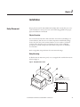
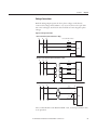
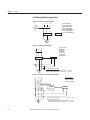
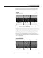
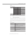
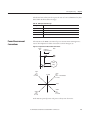
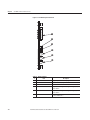
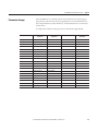
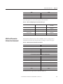
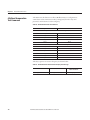
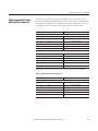
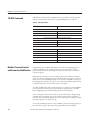
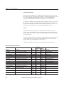
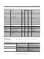
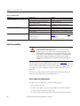
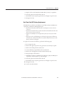
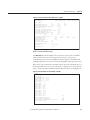
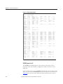
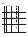
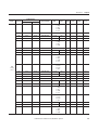
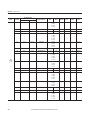
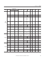
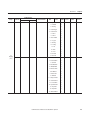
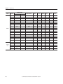
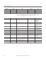
Chapter 11
Testing & Troubleshooting
Table 90 - Troubleshooting
Problem
The relay does not respond to commands from a device
connected to the serial port.
The relay does not respond to faults.
The relay trips on overload sooner than expected.
Possible Cause
Cable is not connected.
Cable is not the correct type.
The relay or device is at an incorrect baud rate or has
another parameter mismatch.
The relay serial port has received an XOFF, halting
communications.
The relay is improperly set.
Improper test source settings.
Current or voltage input wiring error.
Failed relay self-test.
The phase rotation is improperly set.
The FLA is improperly set.
The SF is improperly set.
Solution
Verify the cable connections.
Verify the cable pinout.
Verify Device software setup.
Type <Ctrl> Q to send the relay XON and restart
communications.
Verify the relay settings.
Verify the test source settings.
Verify input wiring.
Use the front panel 4'.#;56#675 function to view selftest results.
Verify phase rotation setting as described in Figure 48 or
Figure 49.
Verify FLA settings.
Verify the Service Factor of the motor.
Field Serviceability
ATTENTION: Disconnect or de-energize all external connections before opening this
device. Contact with hazardous voltages and currents inside this device can cause
electrical shock that can lead to injury or death.
Equipment components are sensitive to electrostatic discharge (ESD). Undetectable
permanent damage can result if you do not use proper ESD procedures. Ground yourself,
your work surface, and this equipment, before removing any cover from this equipment.
If your facility is not equipped to work with these components, contact Rockwell
Automation about returning this device and related Rockwell Automation equipment
for service.
The 825-P firmware can be upgraded in the field (refer to Chapter 13for
firmware upgrade instructions). By monitoring the front-panel messages, the user
will be aware of a self-test failure occurrence. By using the metering functions, the
user will be aware if the analog front-end (not monitored by relay self-test) is
functional.
The only two components that can be replaced in the field are (1) the power
supply fuse and (2) the real-time clock (RTC) battery.
Power Supply Fuse Replacement
To replace the power supply fuse, perform the following steps:
1. De-energize the relay.
2. Remove the eight rear panel screws, ground screw, and relay rear panel.
3. Remove the Slot A printed circuit board.
4. Locate the fuse on the board, then remove the fuse from the fuse holder.
158
Rockwell Automation Publication 825-UM004D-EN-P - November 2012
Testing & Troubleshooting
Chapter 11
5. Replace the fuse with a BUSS 2A/250V ABC (ceramic) or equivalent.
6. Insert the printed circuit board into Slot A.
7. Reinstall the relay rear panel, ground screw, and eight rear panel screws.
8. Energize the relay.
Real-Time Clock (RTC) Battery Replacement
The RTC battery, which is a 3V lithium coin cell battery (Rayovac BR2335 or
equivalent), performs the following functions:
• Powers the clock (date and time) if the external power source is lost or
removed.
• Retains the thermal memory for the thermal overload function when the
power source is lost or removed.
• Operates nominally at room temperature (25°C) for ten years at rated
load.
• Experiences a low self-discharge rate when the relay is powered from an
external source. Thus, battery life can extend well beyond ten years. The
battery cannot be recharged.
To replace the real-time clock battery, perform the following steps:
1. De-energize the relay.
2. Remove the eight rear panel screws, ground screw, and relay rear panel.
3. Remove the Slot B printed circuit board.
4. Locate the battery clip (holder) on the circuit board.
5. Remove the existing battery from beneath the battery clip.
6. Properly dispose of the battery.
7. Install the new battery, 3V lithium coin cell battery (Rayovac BR2335 or
equivalent), with the positive (+) side facing up.
8. Insert the printed circuit board into Slot B.
9. Reinstall the relay rear panel, ground screw, and eight rear panel screws.
10. Energize the relay.
11. Set the relay date and time.
Rockwell Automation Publication 825-UM004D-EN-P - November 2012
159
Chapter 11
Testing & Troubleshooting
Troubleshooting DeviceNet
Table 91 - DeviceNet Troubleshooting Procedures
Table 92 Network Status LED
Off
Definition
The device has not completed the initialization, is not on an
active network, or may not be powered up.
Flashing Green – Red – Off Power-up LED test.
Solid Green
The device is operating in a normal condition, and is
communicating to another device on the network.
Flashing Green
The device is operating in a normal condition, is online, but with
no connection to another device. This is the typical state for new
devices.
Flashing Red
Recoverable fault has occurred.
Solid Red
The device has detected a major error that has rendered it
incapable of communicating on the network (Duplicate MAC ID,
Bus off, media issue).
Flashing Red and Green
The device is in a communication faulted state.
Flashing Red and Green
The device has detected a network access error and is in a
communication faulted state. The device has subsequently
received and accepted an Identify Communication Faulted
Request Protocol message.
Troubleshooting Device
Backplane Communication
Possible Cause
Check to ensure that the product is wired correctly and configured on the network.
No action required.
No action required.
The device could need to be mapped to a master scanner, placed in a scanlist, or have
another device communicate to it.
Ensure that the PLC and scanner are operating correctly and that there are no media
or cabling issues. Check to see if other networked devices are in a similar state.
Troubleshooting should be done to ensure that the network is correct (terminators,
lengths, etc.) and there is not a duplicate node problem. If other devices on the
network appear to be operating fine and power cycling the device does not work,
contact Technical Support.
Power cycling the device could resolve the problem; however, if the problem
continues, it could be necessary to contact Technical Support.
This is not a common state for DeviceNet products. Power cycling the device could
resolve the problem, however if the problem continues it could be necessary to find
out what is causing the problem.
Table 93 - Device Backplane Communication Troubleshooting Procedures
Table 94 Bus Status LED
Off
Green
Red
160
Definition
The device is in Power-up mode.
The device is operating in a normal condition.
The 825-PDN card has lost backplane communications
with the 825-P relay.
Possible Cause
Check to ensure that the product is wired correctly. Confirm that the product has
appropriate DeviceNet and control power. Verify that the 825-PDN card is inserted
correctly.
No action required.
Confirm product has appropriate DeviceNet and control power.
Rockwell Automation Publication 825-UM004D-EN-P - November 2012
Chapter
12
ASCII Serial Communications
Overview
The 825-P Relay has the following ASCII serial communications interfaces:
• PORT 4 — Slot C for optional Modbus network communications.
• PORT F — Front-panel EIA-232 serial port.
This chapter describes the connections and commands used with ASCII serial
communications.
ASCII Serial Port
Operation
Introduction
The serial port interface provides an efficient way to communicate with the relay
using a PC to review and enter the settings, access metering data, review self-test
status, retrieve event summaries, and obtain motor operating statistics reports.
Required Equipment
To connect a PC serial port to the relay front panel serial port and enter relay
commands, the following equipment is required:
• A personal computer equipped with one available EIA-232 serial port
• A standard null-modem communication cable to connect the computer
serial port to the relay serial port
• Terminal emulation software to control the computer serial port
• The 825-P Relay
On most personal computers, the connector for the EIA-232 serial port is a 9-pin
“D” subconnector. You can purchase the cable to connect the computer port to
the relay port from most computer hardware retailers, or you can build your own
cable using the pinouts shown in Table 53.
Rockwell Automation Publication 825-UM004D-EN-P - November 2012
161
Chapter 12
ASCII Serial Communications
You can use a variety of terminal emulation programs on your PC to
communicate with the 825-P. Examples of PC-based terminal emulation
programs include:
• ProComm Plus®
• Relay/Gold
• Microsoft Windows® HyperTerminal
• SmartCOM
• CROSSTALK®
• Tera Term
Connect Your PC to the Relay
Connect the PC serial port to the 825-P serial port using a standard null-modem
communication cable with the pinout shown in Figure 53. For best performance,
the cable should not be more than 15 meters (50 feet) long.
Figure 53 - Serial Cable Pinout
1
825-P Relay
9-Pin Male
“D” Subconnector
Pin Function
RXD
TXD
GND
CTS
1
Pin #
2
3
5
8
DTE Device
9-Pin Female
“D” Subconnector
Pin #
3
2
5
8
7
1
4
6
Pin Function
TXD
RXD
GND
CTS
RTS
DCD
DTR
DSR
DTE = Data Terminal Equipment (e.g., computer, terminal)
Figure 54 shows the front-panel EIA-232 serial port (PORT F) DB-9 connector
pinout for the 825-P. Table 95 shows the pin functions and definitions for the
serial port.
Figure 54 - DB-9 Connector Pinout for EIA-232 Serial Ports
5 4
9 8
162
3 2
1
7 6
Rockwell Automation Publication 825-UM004D-EN-P - November 2012
ASCII Serial Communications
Chapter 12
Table 95 - Pin Functions and Definitions for EIA-232 Serial Port (Port F)
Pin
Pin Function
Definition
1, 4, 6
N/C
No connection
2
RXD, RX
Receive data
3
TXD, TX
Transmit data
5, 9
GND
Signal ground
7
RTS
Request to send
8
CTS
Clear to send
Configure Your Terminal Emulation Software
Personal computers use terminal emulation software to send and interpret
received characters at the EIA-232 serial port. This software allows you to type
letters and numbers to form commands at the computer keyboard and to see the
characters you type and the relay responses on the computer screen. To ensure
the PC communicates correctly with the relay, configure the terminal emulation
software connection properties to match the relay serial port configuration.
Configure the terminal emulation software to match the default settings shown
in Table 96. For the best display, use VT-100 terminal emulation. If VT-100 is
not available, WYSE-100 and ANSI terminal emulations also work.
Table 96 - 825-P Relay Serial Communications Default Settings
Setting
Default
Speed (bps)
9600
Data Bits
8
Parity
N
Stop Bits
1
Flow Control
XON/XOFF (software flow control)
To change the port settings, use the front-panel 5'65*19 2146 settings
menu item.
Serial Port Settings
The 825-P provides settings that allow you to configure the communication
parameters for the front-panel serial port. The front-panel serial port supports
only ASCII communications.
Rockwell Automation Publication 825-UM004D-EN-P - November 2012
163
Chapter 12
ASCII Serial Communications
Table 97 - Front Panel Serial Port Settings
Setting Prompt
Setting Range
Factory Default
SPEED
300–38400 bps
9600
DATA BITS
7, 8 bits
8
PARITY
O, E, N
N
STOP BITS
1, 2 bits
1
PORT TIMEOUT
0–30 min
15
HDWR HANDSHAKING
Y, N
N
The 825-P front-panel serial port supports EIA-232 communication of ASCII
text data. Table 97 shows relay serial port settings for the front-panel port. Set the
Baud Rate, Data Bits, Parity, and Stop Bits settings to match the serial port
configuration of the equipment that is communicating with the serial port.
After Port Timeout minutes of inactivity on a serial port at Access Level 2, the
port automatically returns to Access Level 1. This security feature helps prevent
unauthorized access to the relay settings if the relay is accidentally left in Access
Level 2. If you do not want the port to time out, set Timeout equal to 0 minutes.
The relay EIA-232 serial ports support software (XON/XOFF) flow control. If
you want to enable support for hardware (RTS/CTS) flow control, set the Enable
Hardware Handshaking setting equal to Y.
Using Terminal Commands
When you type commands at the terminal emulation window, type either the
entire command or just use the first three letters (e.g., the following commands
instruct the relay to display metering data):
Type /'6'4 (or /'6) and press Enter.
Use upper- or lower-case characters when typing commands; however, password
entry is case sensitive. Table 99 lists user commands that the relay accepts at the
EIA-232 serial port.
The relay serial port uses software flow control, meaning that character
transmission is controlled by receipt of XON and XOFF characters. When the
relay receives the XOFF character during transmission, it pauses until it receives
an XON character. If a message is not in progress when the relay receives the
XOFF character, it blocks transmission of a message presented to its buffer.
Messages are transmitted after the relay receives the XON character.
You can send control characters from most keyboards using the keystrokes listed
in Table 98.
164
Rockwell Automation Publication 825-UM004D-EN-P - November 2012
ASCII Serial Communications
Chapter 12
Table 98 - Serial Port Control Characters
Control Characters
Key Commands
XON
Ctrl+Q
XOFF
Ctrl+S
CAN
Ctrl+X
You can use the XOFF character to pause in the middle of long transmissions
from the relay. To resume the transmission, use the XON character. To cancel a
transmission in progress, use the Ctrl+X key commands.
Serial Port Access Levels
Issue commands to the relay via the front serial port, e.g., to view metering values
or change the relay settings. Refer to Table 99 available serial port commands.
Access these commands only from the corresponding access level, as listed
in the table.
Access levels are:
• Access Level 0 (the lowest access level)
• Access Level 1
• Access Level 2 (the highest access level)
Access Level 0
Once serial port communications are established with the relay, the relay displays
the = prompt (an equal sign). This is referred to as Access Level 0. The only
command available at Access Level 0 is the ACC command (see Table 99). Type
#%% at the Access Level 0 prompt and then press Enter. The ACC command
takes the relay to Access Level 1.
Access Level 1
The Access Level 1 commands primarily allow you to view information (such as
settings and metering) but not to change settings. When the relay is in Access
Level 1, the relay sends the prompt: =>. Type #% at the prompt and then press
Enter to take the relay to Access Level 2.
Access Level 2
The Access Level 2 commands primarily allow you to change relay settings, reset
data buffers, and control relay outputs. If left in Access Level 2, the serial port
automatically returns to Access Level 1 after a settable inactivity period. All
Access Level 1 commands are also available in Access Level 2. When the relay is in
Rockwell Automation Publication 825-UM004D-EN-P - November 2012
165
Chapter 12
ASCII Serial Communications
Access Level 2, the relay sends the = > > prompt at which you press Enter or after
a command response is finished.
Command Summary
Table 99 lists the serial port commands associated with particular activities. The
commands are shown in upper-case letters, but they can also be entered with
lower-case letters.
Table 99 - 825-P Serial Port Command Summary
Serial Port
Command
Access
Level
Command Description
Page
Number
2ACCESS
1, 2
Go to Access Level 2.
Page 167
ACCESS
0, 2
Go to Access Level 1.
Page 167
ANALOG
2
Test analog output.
Page 167
DATE
1, 2
View or Change date.
Page 167
METER
1, 2
Display metering data.
Page 168
MOTOR
1, 2
Display motor operating statistics report.
Page 170
MOTOR R or C
2
Reset motor operating statistics.
Page 170
PASSWORD
2
View or Change password.
Page 170
QUIT
1, 2
Go to Access Level 0.
Page 171
SER
1, 2
View serialized events recording data.
Page 171
SER R or C
1, 2
Reset serialized events recording data.
Page 171
SET
2
Enter or Change relay settings.
Page 172
SHOW
1, 2
Show/view relay settings.
Page 173
STATUS
1, 2
Display relay self-test status.
Page 174
STATUS R or C
2
Clear self-test status and restart relay.
Page 177
STOP
2
Stop motor.
Page 177
STR
2
Start motor.
Page 177
SUMMARY
1, 2
View event summary reports.
Page 177
SUMMARY R or C
1, 2
Reset event summary buffer.
Page 178
TARGET
1, 2
Display relay elements, inputs or outputs status.
Page 178
TARGET R
2
Reset trip/target LEDs.
Page 179
TIME
1, 2
View or Change time.
Page 179
The serial port command explanations that follow in the Description of
Commands subsection are in alphabetical order to correspond with Table 99.
166
Rockwell Automation Publication 825-UM004D-EN-P - November 2012
ASCII Serial Communications
Description of Commands
Chapter 12
Each command explanation lists:
• Command.
• Serial port access levels where the command is available, in parentheses.
• Explanation of the command use or response.
For example, issue the DATE command from serial port Access Level 1 or 2.
ACC and 2AC (Level 1 or 2)
The ACC and 2AC commands provide entry to the multiple access levels.
Different commands are available at the different access levels, as shown in
Table 99. Commands ACC and 2AC operate similarly:
• ACC command moves the relay from Access Level 0 to Access Level 1 or
Access Level 2 to Access Level 1.
• 2AC command moves the relay from Access Level 1 to Access Level 2.
The relay is shipped from the factory with the Access Level 1 and Access Level 2
passwords disabled. See PASSWORD (Level 1 or 2) on page 170 for
information on Access Level 1 and Access Level 2 password protection.
The relay sets the SALARM Relay Word bit for one second after a successful
move to Access Level 2.
ANALOG (Level 2)
Use the ANALOG p t command to test the relay analog current output. When
you use this command, the relay ends normal analog current output and sends a
signal defined by the percentage value, p = 0…100% for t minutes (t = 1…10
minutes). For example, when the analog output signal type is 4…20 mA, the
command ANA 75 5.5 instructs the relay to output 16 mA (75% of full scale) for
5.5 minutes or until a character or space key is pressed to end the test.
You can also use the ANALOG command to generate a current signal that
increases linearly. Replace the fixed percentage value with an R to ramp the signal
from zero to full scale over time. For example, the command ANA R 10 instructs
the relay to ramp the analog signal from zero to full scale, reaching full scale in 10
minutes. Stop the test by pressing a keyboard character key or the space bar.
DATE (Level 1 or 2)
DATE displays the date stored by the internal calendar/clock.
Rockwell Automation Publication 825-UM004D-EN-P - November 2012
167
Chapter 12
ASCII Serial Communications
If the date format setting DATE_F is set to MDY, the date is displayed as
month/day/year. If the date format setting is set to YMD, the date is displayed as
year/month/day and for DMY it is displayed as day/month/year.
To set the date (and the date format setting is MDY), type &#6'OOFF[[[[
and then press Enter.
To set the date for a date format setting of YMD, type &#6'[[[[OOFF and
then press Enter.
To set the date for a date format setting of DMY, type &#6'FFOO[[[[ and
then press Enter.
You can separate the month, day, and year parameters with spaces, commas,
slashes, colons, or semicolons.
METER (Level 1 or 2)
The METER commands provide access to the relay metering data. The relay
divides the displayed information into two groups:
Note: All ASCII command responses in this section are examples only. Your
specific relay has differences based on model number, firmware revision number,
and application.
• Instantaneous
• Thermal and RTD
METER k (Instantaneous Metering)
The METER k command displays instantaneous magnitudes (and angles, if
applicable) of the measured and calculated analog quantities.
All angles are displayed between –180 and +180 degrees. For delta-connected
PTs, angles are referenced to VAB or L1 and for wye-connected PTs, angles are
referenced to VAN or L1.
If the voltage channels are not supported, or VAB < 13V (for delta) or
VAN < 13V (for wye), angles are referenced to L1 current.
To view the instantaneous meter values once, use the METER command (see the
example in Figure 55). To view the meter values M times, use the METER k
command, where M is a number between 1 and 32767.
168
Rockwell Automation Publication 825-UM004D-EN-P - November 2012
ASCII Serial Communications
Chapter 12
Figure 55 - View Instantanious Meter Values Once - Example
=>>MET
825-P Modular
Prot. System
Date: 03/05/2003
Time: 16:44:08.404
L1
L2
L3
Current Magnitude (A)
21.2
21.3
21.5
Current Angle (deg)
-42.0
-162.5
78.2
Average Current Magnitude (A)
21.3
Motor Load (x Ie)
0.9
GF Current-Core Balance (A)
0.00
GF Current-Core Balance Angle (deg) -76.6
GF Current-Residual (A)
0.0
GF Current-Residual Angle (deg)
72.3
Current Imbalance (%)
1.0
VAN
VBN
VCN
VG
Voltage Magnitude L-N (V)
334
334
334
Voltage Angle (deg)
0.0
-119.6
120.8
Average Phase (V)
334
Voltage Imbalance (%)
0.0
Real Power (kW)
16
Reactive Power (kVAR)
14
Apparent Power (kVA)
21
Power Factor
0.74 LAG
Frequency (Hz)
=>>
4
-116.1
60.0
METER T (Thermal and RTD Metering)
The METER T command displays the temperatures of any connected RTDs.
This command also shows the average motor current (x Ie), the present
% Thermal Capacity used, and the RTD % Thermal Capacity (if ambient and
winding temperatures are monitored and a winding RTD trip temperature is set).
If the motor is in overload, this command response shows the calculated time to a
thermal trip. If the motor is not in overload (e.g., see Figure 56), the time shown is
9999 seconds. The Starts Available and Time To Reset values are also displayed.
Figure 56 - Calculated Time to a Thermal Trip - Example
=>>MET T
825-P Modular
Date: 03/05/2003
Prot. System
Max Winding RTD = 61 C
Max Bearing RTD = 48 C
Ambient RTD
= 28 C
Max Other RTD
= 50 C
RTD 1 WDG = 61 C
RTD 2 NONE
RTD 3 WDG = 59 C
RTD 4 WDG = 58 C
RTD 5 WDG = Open
RTD 6 WDG = 57 C
RTD 7 BRG = 48 C
RTD 8 BRG = 46 C
RTD 9 BRG = 45 C
RTD 10 BRG = 44 C
RTD 11 AMB = 28 C
RTD 12 OTH = 50 C
Motor Load (x Ie)
0.9
Thermal Capacity Used (%)
32
RTD % Thermal Capacity (%)
27
Calculated Time to Thermal Trip (sec)
9999
Time to Reset (min)
0
Time: 16:13:50.321
=>>
Rockwell Automation Publication 825-UM004D-EN-P - November 2012
169
Chapter 12
ASCII Serial Communications
MOTOR (Level 1 or 2)
The MOTOR command displays the motor operating statistics that include the
following:
• Motor running time, stopped time, and percent time running.
• Total number of motor starts.
• Number of emergency starts.
Chapter 7, Metering & Monitoring, includes additional details on the motor
operating statistics report. Issuing the MOTOR R or MOTOR C command
from Access Level 2 clears the report.
PASSWORD (Level 1 or 2)
NOTE:
This device is shipped with Access Level 1 and Access Level 2 password protection disabled.
Access Level 1 and Access Level 2 password protection must be restored at installation.
Failure to install Access Level 1 and Access Level 2 private passwords could allow
unauthorized access. Rockwell Automation is not be responsible for damage resulting
from unauthorized access.
The Access Level 2 PAS command allows you to inspect or change the existing
password. To inspect the Access Level 1 and Access Level 2 passwords, type 2#5
and then press Enter.
The relay displays the present passwords.
The factory ships the relay with the passwords disabled.
For example, to change the password for Access Level 2 to BIKE, type PAS 2
BIKE and then press Enter.
After entering the new password, type 2#5 and then press Enter to inspect it.
If the password is correct, record it for future reference. If you make three
incorrect password guesses, access is denied and the SALARM Relay Word bit is
set for one second.
The password can include up to eight characters. Valid characters consist of all
printable characters from the 7-bit ASCII set typically found on the PC
keyboard. The space character is not included.
Strong passwords consist of eight characters, with at least one special character or
digit and mixed-case sensitivity, but do not form a name, date, acronym, or word.
Passwords formed in this manner are less susceptible to password guessing and
automated attacks.
170
Rockwell Automation Publication 825-UM004D-EN-P - November 2012
ASCII Serial Communications
Chapter 12
To disable password protection for Access Level 1 or Access Level 2, set its
password to DISABLE.
QUIT (Level 1 or 2)
The QUI command returns the relay to Access Level 0 from either Access Level 1
or Access Level 2.
SER (Level 1 or 2)
Use the SER command to view the Serialized Events Recording (SER) report,
described in detail in Chapter 8: Analyzing Events.
Each event record is stored with a record number, a date, and a time. You can
access SER data by record number or by date. The most recent record is always
record number 1. The various SER command options are shown in Table 100.
Table 100 - SER Command Options
Serial Port Command
Description
SER
Display all SER records.
SER n
Display the n most recent SER records starting with record n.
SER n1 n2
Display SER records n2 to n1, starting with n2
SER d1
Display all SER records made on date d1
SER d1 d2
Display all SER records made from dates d2 to d1, inclusive, starting with d2
The date entries used with the SER command are dependent on the Date Format
setting. If the Date Format setting equals MDY, then use the format mm/dd/yyyy
for entered dates. If the Date Format setting equals YMD, then use the format
yyyy/mm/dd for the entered dates. If the Date Format setting equals DMY, then
use the format dd/mm/yyyy for the entered dates.
If the requested SER records do not exist, the relay displays the message 0Q5'4
&CVC
SER R or C (Level 1 and 2)
The SER R or SER C command removes the SER data from nonvolatile
memory.
Rockwell Automation Publication 825-UM004D-EN-P - November 2012
171
Chapter 12
ASCII Serial Communications
SET (Level 2)
The SET command allows you to view or change the relay settings.
Table 101 - Serial Port SET Commands
Command
Settings Type
Description
SET
Relay
Protection elements, timers, etc.
SET P
Port
Serial port settings for Serial Port F
SET M
Relay
I/O mapping settings
When you issue the SET command, the relay presents a list of settings one at a
time. Enter a new setting or press Enter to accept the existing setting. Editing
keystrokes are shown in Table 102.
Table 102 - SET Command Editing Keystrokes
Do the Following
Results
Press Enter
Retains setting and moves to next setting.
Type ^ and then press Enter
Returns to previous setting.
Type < and then press Enter
Returns to previous setting category.
Type > and then press Enter
Moves to the next setting category.
Type END and then press Enter
Exits editing session, then prompts you to save settings.
Press Ctrl+ X
Aborts editing session without saving changes.
The relay checks each entry to ensure that it is within the setting range. If it is not,
an 1WVQH4CPIG message is generated, and the relay prompts you for the setting
again.
When all the settings are entered, the relay displays the new settings and prompts
you for approval to enable them. Type ; and then press Enter to enable the new
settings. The relay is disabled for as long as five seconds while it saves the new
settings. The SALARM Relay Word bit is set momentarily and the ENABLE
LED extinguishes while the relay is disabled.
To change a specific setting, enter the command shown in Table 103.
Table 103 - SET Command Format
SET n s TERSE
Where:
172
n
is left blank to enter relay settings.
n
is P to enter front serial port settings.
Rockwell Automation Publication 825-UM004D-EN-P - November 2012
ASCII Serial Communications
Chapter 12
Table 103 - SET Command Format
SET n s TERSE
n
is M to enter I/O mapping settings.
s
is the short parameter name of the specific setting you want to jump to and begin setting.
If s is not entered, the relay starts at the first setting (e.g., enter 50PIP to start at Short Circuit Trip
level setting).
TERSE
instructs the relay to skip the settings display after the last setting.
Use this parameter to speed up the SET command.
If you want to review the settings before saving, do not use the TERSE option.
SHOW
Use the SHOW command to view relay settings and serial port settings (see
Figure 61. The SHOW command options are listed in Table 104.
Table 104 - SHOW Command Options
Command
Description
SHOW
Show relay settings.
SHO A
Show all relay settings: enabled, disabled/hidden.
SHO P
Show serial port settings.
SHO M
Show I/O mapping settings.
You can append a setting name to each of the commands to specify the first
setting to display (e.g., SHO 50P1P displays the relay settings starting with
setting 50P1P). The default is the first setting.
The SHOW command displays only the enabled settings. To display all the
settings, including disabled/hidden settings, append an A to the SHOW
command (e.g., SHOW A).
Rockwell Automation Publication 825-UM004D-EN-P - November 2012
173
Chapter 12
ASCII Serial Communications
Figure 57 - SHOW Command Example
=>SHO
RID
:=825-P Modular
TID
:=Prot. System
PHROT
:= ABC
FNOM
:=
FLA1
:= 25.0
E2SPEED :=
VNOM
:= 600
DELTA_Y :=
E49MOTOR:= Y
49RSTMD :=
LRA1
:= 12.0
LRTHOT1 :=
TCAPU
:= 85
TCSTART :=
50P1P
:= OFF
50P2P
:=
50G1P
:= OFF
50G2P
:=
LJTPU
:= OFF
LJAPU
:=
LLTPU
:= OFF
LLAPU
:=
46UBT
:= OFF
46UBA
:=
THERBL_T:= OFF
START_T := OFF
ESTAR_D := N
MAXSTART:= OFF
TBSDLY :=
ABSDLY := OFF
E47T
:= N
SPDSDLYT:= OFF
SPDSDLYA:=
EPTC
:= N
E49RTD := Y
RTDRST :=
TRTMP1 := 150
ALTMP1 :=
RTD3TY := PT100
TRTMP3 :=
RTD4TY := PT100
TRTMP4 :=
RTD5TY := PT100
TRTMP5 :=
RTD6TY := PT100
TRTMP6 :=
RTD7TY := PT100
TRTMP7 :=
RTD8TY := PT100
TRTMP8 :=
RTD9TY := PT100
TRTMP9 :=
RTD10TY := PT100
TRTMP10 :=
RTD11TY := PT100
TRTMP11 :=
RTD12TY := PT100
TRTMP12 :=
EBRGV
:= N
ERTDBIAS:=
27P1P
:= OFF
27P2P
:=
59P1P
:= OFF
59P2P
:=
NVARTP := OFF
PVARTP :=
37PTP
:= OFF
37PAP
:=
55LGTP := 0.50
55LDTP :=
55LDAP := OFF
55AD
:=
81D1TP := OFF
81D1AP :=
81D2TP := OFF
81D2AP := OFF
LOAD
:= OFF
AOPARM := LOAD_I
BLK46
:= N
BLK48
:=
BLK37
:= N
BLK66
:=
TRIPFS := Y
AUX1FS :=
AUX4FS := Y
AUX5FS :=
T1ONDLY := 0
T1OFFDLY:=
FP_TO
:= 15
FP_CONT :=
FP_TD
:= N
FP_GC
:=
FP_TH
:= N
FP_VA
:=
=>
60
N
WYE
AUTO
10.0
OFF
OFF
OFF
OFF
OFF
10
DATE_F
CTRN
:= MDY
:= 100
49RSTP :=
TD1
:=
COOLTIME:=
50N1P
:=
75
1.00
44
OFF
CTR1
PTR
:= 5
:= 5.00
SF
:=
RTC1
:=
ETHMBIAS:=
50N2P
:=
1.00
AUTO
Y
OFF
46UBAD
:= 10
PROTBL_T:= OFF
AUTO
120
OFF
OFF
OFF
OFF
OFF
OFF
OFF
OFF
OFF
OFF
N
OFF
OFF
OFF
OFF
OFF
1
OFF
RTD1LOC
RTD2LOC
ALTMP3
ALTMP4
ALTMP5
ALTMP6
ALTMP7
ALTMP8
ALTMP9
ALTMP10
ALTMP11
ALTMP12
:=
:=
:=
:=
:=
:=
:=
:=
:=
:=
:=
:=
RTD1TY :=
RTD3LOC :=
RTD4LOC :=
RTD5LOC :=
RTD6LOC :=
RTD7LOC :=
RTD8LOC :=
RTD9LOC :=
RTD10LOC:=
RTD11LOC:=
RTD12LOC:=
EWDGV
:=
NVARAP
:= OFF
PVARAP
:= OFF
55TD
:= 1
55LGAP
:= 0.50
N
N
Y
Y
0
5
N
N
BLK50EF :=
BLK49PTC:=
AUX2FS :=
AUX6FS :=
T2ONDLY :=
OFF
OFF
FP_LA
FP_PE
WDG
OFF
OFF
OFF
OFF
OFF
OFF
OFF
OFF
OFF
OFF
OFF
N
N
Y
Y
0
:= N
:= N
PT100
WDG
WDG
WDG
WDG
BRG
BRG
BRG
BRG
AMB
OTH
N
BLK50P := N
BLK49RTD:= N
AUX3FS := Y
T2OFFDLY:= 0
FP_MF
FP_RTD
:= N
:= N
STATUS (Level 1 or 2)
The STATUS command displays the relay hardware and software self-test
diagnostics and resolves hardware configuration conflicts when detected (see
Figure 58).
To view a status report, enter the STATUS command. To view the status report k
times, enter the command STATUS k, where k is a number between 1 and 32767.
Table 105 shows the status report definitions and message formats for each test.
174
Rockwell Automation Publication 825-UM004D-EN-P - November 2012
ASCII Serial Communications
Chapter 12
Table 105 - STATUS Command Report and Definitions
STATUS Report
Designator
Definition
FID
Firmware identifier string
CID
Firmware checksum identifier
Identity Code
Relay configuration identification
Message Format
(FID string)
xxxx
Identity string
Current Offset
(L1, L2, L3, RES, CB)
DC offset in hardware circuits of current channels
OK/WARN
Voltage Offset
(VA, VB, VC)
DC offset in hardware circuits of voltage channels
OK/WARN
PS_Vdc
Power supply status
OK/FAIL
FPGA
FPGA programming unsuccessful, or FPGA failed
OK/FAIL
GPSB
General Purpose Serial Bus
OK/FAIL
HMI
front panel FGPA programming unsuccessful, or front panel
FPGA failed
OK/WARN
RAM
Volatile memory integrity
OK/FAIL
ROM
Firmware integrity
OK/FAIL
CR_RAM
Integrity of settings in RAM and code that runs in RAM
OK/FAIL
Non_Vol
Integrity of data stored in nonvolatile
memory
OK/FAIL
Clk_Bat
Clock battery integrity
OK/WARN
Clock
Clock functionality
OK/WARN
PTC
Integrity of PTC
OK/FAIL
RTD
Integrity of RTD module/communications
OK/FAIL
MCM/CWE
Integrity of current board and MCM/CWE
OK/FAIL
Voltage
Integrity of voltage board
OK/FAIL
I/O_Crd
Integrity of I/O card
OK/FAIL
COM_Crd
Integrity of DeviceNet card and network
OK/FAIL
DeviceNet card specific card identification.
xxxxxx
MAC ID
ASA
Manufacturer identifier for DeviceNet.
xxxx xxxxx
DN_Rate
DeviceNet card network communications data speed
___ kbps
DN_Status
DeviceNet connection and fault status.
000b bbbb
Rockwell Automation Publication 825-UM004D-EN-P - November 2012
175
Chapter 12
ASCII Serial Communications
Figure 58 - STATUS Command - Example
=>>STA
825-P Modular
Prot. System
Date: 03/03/2003
FID=825-P-R100-V0-Z001001-D20030225
Time: 11:54:40.361
CID=010C
Identity Code 1522001BCX0X1X1X
SELF TESTS
Current
Offset:
L1
OK
L2
OK
L3
OK
Voltage
Offset:
VA
OK
VB
OK
VC
OK
PS_Vdc
OK
FPGA
OK
GPSB
Ok
HMI
Ok
RAM
OK
ROM
OK
CR_RAM
OK
Non_Vol
OK
PTC
OK
RTD
Ok
MCM/CWE
OK
OK
MAC_ID
0
ASA
0000 0000h
RES
OK
CB
OK
Clk_Bat
Ok
Clock
OK
Voltage
OK
DN_Rate
0kbps
I/O_Crd
OK
Com_Crd
DN_Status
0000 0000
Relay Enabled
=>>
Figure 59 - Identity Code Explanation
1 5 5 2 0 0 1 B A X O X O A O X
Converter Module
X None
A 825-MCM2
B 825-MCM5
C 825-MCM20
D 825-MCM180
E 825-MCM420
F 825-MCM630N
Communication Card Expansion I/O Card
0 None
0 None
3 DeviceNet
1 Installed
Voltage Sensing Card
0 None
1 Installed
Figure 60 - DN_Status Explanation
0 0 0 0
Undefined
I/D Idle
I/O Fault
Explicit Fault
I/O Connection
Explicit Connection
176
Rockwell Automation Publication 825-UM004D-EN-P - November 2012
0 0 0 0
ASCII Serial Communications
Chapter 12
STATUS R or C (Level 2)
To reset the self-test status and restart the relay, enter the STA R command from
Access Level 2.
The relay then restarts (like powering down and then powering up the relay) and
all diagnostics are rerun before the relay is enabled.
STOP (Level 2)
The STOP command causes the relay to trip, opening the motor contactor or
circuit breaker and stopping the motor. For more details refer to Chapter 6:
Configuring Protection & Logic Functions.
STR (Level 2)
The STR (START) command initiates a motor start using the relay's internal
logic. For more details refer to Chapter 6: Configuring Protection & Logic
Functions.
SUMMARY (Level 1 or 2)
The SUM n command displays a summary list, in reverse chronological order, of
all the archived event summary reports (maximum of five events).
An example event summary report is in Figure 61. Each event summary report
shows the date, time, current magnitudes (primary values) and, if the relay has the
voltage option, voltage magnitudes (primary values). The current and voltage
values are at the trigger instant. The event summary report also shows the event
type (e.g., OVERLOAD TRIP).
The n parameter with the SUM n command can have a value up to 5 and defines
the number of events requested. If n is not specified, then up to five of the most
recent reports are listed.
For more information on events, refer to Chapter 8, Analyzing Events.
Rockwell Automation Publication 825-UM004D-EN-P - November 2012
177
Chapter 12
ASCII Serial Communications
Figure 61 - SUMMARY Command - Example
=>>SUM 2
825-P Modular
Prot. System
Event #: 1
Event Date: 01/29/2003
CURRENT MAG (A)
Event #: 2
Event Date: 01/29/2003
CURRENT MAG (A)
Date: 02/04/2003
Time: 17:20:46.439
Event: OVERLOAD TRIP
Event Time: 14:14:01.930
L1
L2
L3
8.2
8.1
8.2
Event: OVERLOAD TRIP
Event Time: 14:13:05.931
L1
L2
L3
8.2
8.2
8.2
RES
0.0
CB
0.00
RES
0.0
CB
0.00
=>>
SUMMARY R (Level 1 and 2)
The SUMMARY R command clears all the events in the event buffer.
TARGET (Level 1 or 2)
The TARGET command displays the status of relay elements whether they are
asserted or de-asserted. The elements are represented as Relay Status bits and are
listed in rows of eight, called Relay Status rows. For additional information on
individual Relay Status bits, refer to Appendix C, Relay Word Bits.
A Relay Word bit is either at logical 1 (asserted) or at logical 0 (de-asserted).
The TAR command options are listed in Table 106.
Table 106 - TARGET Command Options
Commands
Descriptions
TAR n k
Shows Relay Word Row n (0–10).
k is an optional parameter to specify the number of times (1–32767) to repeat the Relay Word
row display.
If k is not specified, the Relay Word row is displayed once.
See Table 106 for the definition of Row 0.
See Table for a list of the Relay Word bits in each row (n = 1–10).
TAR name k
Shows the Relay Word bit row containing the Relay Word bit name (e.g., TAR 50P1T displays
Relay Word Row 1).
Valid names are shown in TARGET R (Level 2) on page 179.
k is an optional parameter to specify the number of times (1–32767) to repeat the Relay Word
bit row display.
If k is not specified, the Relay Word row is displayed once.
Table 107 - Front-Panel LEDs and the TAR 0 Command
178
LED Number/State
7
6
5
4
3
2
1
0
ALARM (Flashing)
N/A
WARNING
N/A
N/A
N/A
N/A
N/A
N/A
ON Steady (Latched)
ENABLE
TRIP
N/A
N/A
N/A
N/A
N/A
N/A
Rockwell Automation Publication 825-UM004D-EN-P - November 2012
ASCII Serial Communications
Chapter 12
TARGET R (Level 2)
The TARGET R command resets the front-panel tripping targets and releases
the trip signal if the fault condition has vanished and lockout conditions are not
present. If you issue the TARGET R command at the relay serial port or use the
front-panel Test/Reset push button and the relay tripping targets do not reset,
verify that the fault condition and all lockouts have cleared.
TIME (Level 1 or 2)
The TIME command displays the relay clock (24 hours). To set the clock, type
6+/'JJOOUU and then press Enter.
Separate the hours, minutes, and seconds with colons, semicolons, spaces,
commas, or slashes. For example, set 22:47:36 by typing 6+/' and
then pressing Enter:
View or Change Settings with View Settings
Front Panel Serial Port
Use the SHOW command to view relay settings. The SHOW command is
available from Access Level 1 and Access Level 2.
Table 108 lists the SHOW command options.
Table 108 - SHOW Command Options
Command
Description
SHOW
Show relay settings.
SHO A
Show all relay settings: enabled, disabled/hidden.
SHO P
Show front serial port settings.
SHO M
Show I/O mapping settings.
You can append a setting name to each of the commands to specify the first
setting to display (e.g., SHO 50P1P displays the relay settings starting with
setting 50P1P). The default is the first setting.
The SHOW command displays only the enabled settings. To display all the
settings, including disabled/hidden settings, append an A to the SHOW
command (e.g., SHOW A).
Rockwell Automation Publication 825-UM004D-EN-P - November 2012
179
Chapter 12
ASCII Serial Communications
Enter Settings
The SET command (available from Access Level 2) allows you to view or change
the settings. Table 109 lists the SET command options.
Table 109 - SET Command Options
Command
Settings Type
Description
SET
Relay
Protection elements, timers, etc.
SET P
Port
Settings for front panel Serial Port F.
SET M
Relay
Input/output mapping settings.
When you issue the SET command, the relay presents a list of settings one at a
time. Enter a new setting or press <Enter> to accept the existing setting. Editing
keystrokes are listed in Table 110.
Table 110 - SET Command Editing Keystrokes
Keystroke
Results
Press Enter
Retains setting and moves to next setting.
Type ^ and press Enter
Returns to previous setting.
Type < and press Enter
Returns to previous setting category.
Type > and press Enter
Moves to next setting category.
Type END and press Enter
Exits editing session, then prompts you to save settings.
Press Ctrl+ X
Aborts editing session without saving changes.
The relay checks each entry to ensure that the entry is within the setting range. If
it is not in range, an 1WVQH4CPIG message is generated, and the relay prompts
you for the setting again.
When all the settings are entered, the relay displays the new settings and prompts
you for approval to enable them. Type ; and then press Enter to enable the new
settings. The relay is disabled for as long as 5 seconds while it saves the new
settings. The ALARM Relay Word bit is set momentarily and the Enable LED
extinguishes while the relay is disabled.
The relay also runs interdependency checks between some parameters. If it
detects a configuration error between parameters a message is displayed and the
user is prompted to change settings to eliminate error before settings can be saved.
180
Rockwell Automation Publication 825-UM004D-EN-P - November 2012
ASCII Serial Communications
Chapter 12
To change a specific setting, enter the command shown in Table 111.
Table 111 - SET Command Format
SET n s TERSE
Where:
n
is left blank to enter RELAY settings.
n
is P to enter front panel serial port settings.
n
is M to enter I/O mapping settings.
s
is the name of the specific setting you want to jump to and begin setting.
If s is not entered, the relay starts at the first setting (e.g., enter 50P1P to start at Short Circuit
Trip level setting).
TERSE
instructs the relay to skip the settings display after the last setting.
Use this parameter to speed up the SET command.
If you want to review the settings before saving, do not use the TERSE option.
Rockwell Automation Publication 825-UM004D-EN-P - November 2012
181
Chapter 12
182
ASCII Serial Communications
Rockwell Automation Publication 825-UM004D-EN-P - November 2012
Chapter
13
Firmware Upgrade Instructions
Overview
Rockwell Automation occasionally offers firmware upgrades to enhance the
performance of your relay. Since the 825-P relay stores firmware in flash memory,
changing physical components is not necessary. Upgrade the relay firmware by
downloading a file from a personal computer to the relay via the front panel serial
port as outlined in the following sections.
Required Equipment
Gather the following equipment before starting this firmware upgrade:
• Personal computer (PC)
• Terminal emulation software that supports XMODEM/CRC protocol
(e.g., Microsoft® Windows® HyperTerminal)
• Serial communication cable (null-modem cable)
• Disk containing the firmware upgrade (*.S19) file
Upgrade Instructions
The instructions below assume you have a working knowledge of your personal
computer terminal emulation software. In particular, you must be able to modify
your serial communications parameters (baud rate, data bits, parity, etc.), select
transfer protocol (XMODEM/CRC), and transfer files (e.g., send and receive
binary files).
1. If the relay is in service, open its motor control circuits.
2. Connect the PC to the front-panel serial port and enter Access Level 2.
3. Save the current relay settings.
a. Issue the following commands at the ASCII prompt:
SHO, SHO P, and SHO M.
b. Issue the L_D command to the relay.
c. Type Y and press the Enter key at the following prompt:
Disable relay to send or receive firmware (Y/N)?
d. Type Y and press the Enter key at the following prompt:
Are you sure (Y/N)?
The relay sends the BOOTLDR !> prompt.
4. Type BAU 38400 and press the Enter key.
Rockwell Automation Publication 825-UM004D-EN-P - November 2012
183
Chapter 13
Firmware Upgrade Instructions
This changes the baud rate of the communications port to 38400. Change the
baud rate of the PC to 38400 to match the relay.
5. Begin the transfer of new firmware to the relay by issuing the REC
command.
6. Type Y to erase the existing firmware or press the Enter key to abort.
7. Press any key (e.g., the Enter key) when the relay sends a prompt.
8. Start the file transfer.
a. Select the send file option in your communications software.
Use the XMODEM protocol and send the file that contains the new
firmware (e.g., R101xxxx.S19).
The file transfer takes less than 10 minutes at 38400 baud. After the transfer is
complete, the relay reboots and returns to Access Level 1.
Figure 62 shows the screen display for the process outlined previously in Upgrade
Instructions.
Figure 62 - Firmware File Transfer Process
=>>L_D <Enter>
Disable relay to send or receive firmware (Y/N)? Y <Enter>
Are you sure (Y/N)? Y <Enter>
Relay Disabled
!>BAU 38400 <Enter>
!>REC <Enter>
Caution! - This command erases the relay’s firmware.
If you erase the firmware, new firmware must be loaded into the relay
before it can be put back into service.
Are you sure you wish to erase the existing firmware? (Y/N) Y
Erasing
Erase successful
Press any key to begin transfer, then start transfer at the PC <Enter>
Upload completed successfully. Attempting a restart
9. The relay illuminates the ENABLE front-panel LED if the relay settings
were retained through the download.
If ENABLE LED is illuminated, proceed to Step 10.
If ENABLE LED is not illuminated or the front-panel displays STATUS
FAIL EEPROM FAILURE, reload the relay settings with the following steps:
a. Set the communications software settings to 9600 baud, 8 data bits, and
1 stop bit.
b. Enter Access Level 2 by issuing the 2AC command.
c. Issue the R_S command to restore the factory default settings.
The relay then reboots with the factory default settings. If the following
message appears during the restart, please contact your local
Allen-Bradley distributor.
Calibration settings lost, please call the factory!
184
Rockwell Automation Publication 825-UM004D-EN-P - November 2012
Firmware Upgrade Instructions
Chapter 13
d.
e.
f.
g.
Enter Access Level 2.
Issue STATUS command, and verify that the relay status is OK.
Set the relay clock and calendar using the DATE and TIME commands.
Set the Relay and Port settings using the following commands: SET,
SET M, and SET P.
h. Set the relay passwords with the PAS command.
10. Set the communications software settings (baud rate, number of data bits,
number of stop bits) to agree with the port settings of the 825-P.
11. Issue the STATUS command, and then verify that all relay self-test results
are OK.
12. Apply current and voltage signals to the relay.
13. Issue the METER command, and then verify that the current and voltage
signals are correct.
The relay is now ready for your commissioning procedure.
Rockwell Automation Publication 825-UM004D-EN-P - November 2012
185
Chapter 13
186
Firmware Upgrade Instructions
Rockwell Automation Publication 825-UM004D-EN-P - November 2012
Appendix
A
Specifications
Electrical Ratings
Main Circuits
825 Converter Module
MCM2
MCM5
MCM20
MCM180
MCM420
MCM630N
825-MCM Converter Modules
Rated Operating Voltage Ue —
IEC: 400 V AC
CSA/UL: 240V AC
690V AC
600V AC
1,000V AC
600V AC
Rated Impulse Strength Uimp
2.5 kV
Operating Current Range (A)
0.5-2.5
1-5
6 kV
2.5-20
20-180
160-420
160-630
Rated Continuous Thermal Current
(A)
3
6
24
216
504
756
Rated Saturation Current
30
60
240
1350
3400
4600
Rated Frequency
8 kV
50/60 Hz ± 3 Hz
Voltage Input Option Card
Rated Operating Voltage Ue
67…300V AC (line-to-line)
Operating Range
0.80…1.1 Ue
Rated Continuous Voltage
300V AC
Rated Insulation Voltage Ui
300V AC
Rated Impulse Strength Uimp
4 kV
Rated Frequency
Transition Voltage
50/60 Hz ± 5 Hz
5…15V
20…79V
PTC Thermistor Input
Type of Control Unit
Max. No. of Sensors in Series
Max. Cold Resistance of PTC Sensor
Chain
Mark A
6
1500 Ω
Trip Resistance
3400 Ω± 150 Ω
Reset Resistance
1500 Ω…1650 Ω
Short Circuit Trip Resistance
Rockwell Automation Publication 825-UM004D-EN-P - November 2012
25Ω ± 10Ω
187
Chapter A
Specifications
Control Circuits
Supply
Rated Supply Voltage Us
110…240V AC, 110…250V DC 24…48V DC
Operating Range
0.80…1.1 Us
Rated Frequency (V AC)
50/60 Hz ± 5 Hz
Max. Power Consumption
AC: 15VA, DC: 15 W
0.80…1.1 Us
Output Relays
Type of Contacts
Trip
Aux1…Aux 6
Rated Insulation Voltage Ui
300V AC
Rated Operating Voltage Ue
240V AC
Rated Impulse Strength Uimp
4kV
Rated Thermal Current Ithe
5A
Rated Operating Current Ie
120V AC
240V AC
Contact Rating Designation
B300
Utilization Category
AC15
Contact Reliability
5 mA @ 17V
Mechanical Durability
10000 no load operations
Pickup Time
< 10 ms
Dropout Time
< 8 ms (typical))
Form C DPDT
Form A SPDT – NO
3A
1.5 A
DC Current Ratings ➊
24V DC
0.75 A
48V DC
0.50 A
125V DC
0.30 A
250V DC
0.20 A
IN1 and IN2
IN3, IN4 and IN5
24V AC/DC
120V AC/DC (825-PIOD)
24V AC/DC (825-PIOR)
Inputs
Rated Operating Voltage Ue
Operating Range
0.80…1.1 Ue
Rated Insulation Voltage Ui
300V AC
Rated Impulse Strength Uimp
4kV
Rated Frequency (AC)
50/60 Hz ± 5 Hz
On-State Voltage
15V
79V
On-State Current (turn-on)
2 mA
2 mA
Steady State Current
15 mA
15 mA
Off-State Voltage
5V
20V
Off-State Current
0.5 mA
1 mA
➊ Capacity at L/R = 40 ms
188
Rockwell Automation Publication 825-UM004D-EN-P - April 2012
Specifications
Chapter A
Mechanical Ratings
Environmental
Ambient Temperature
Humidity (Operating)
Maximum Altitude
Vibration (per IEC 68-2-6)
Shock (per IEC 68-2-27)
Control Terminals
Terminal Screw
Cross Section (1 wire, stranded/solid)
Torque
Degree of Protection
Ground Screw
Terminal Screw
Torque
Storage: -40…+85°C (-40…+185°F)
Operating (open): -20…+60°C (-4…+140°F)
5…95% Non-condensing
2000 m
3G
30 G
M3
0.14…2.5 mm2/#20…12 AWG
0.79 N•m/7lb-in
IP20
#6
1.4 N•m/12 Lb-in
RTD Scanner Module
Supply
Rated Supply Voltage Us
Operating Range
Rated Frequency
Max. Power Consumption
Rated Insulation Voltage Ui
Rated Impulse Strength Uimp
Pollution Degree
Environmental
Ambient Temperature Storage
Humidity (Operating)
Maximum Altitude
Vibration (per IEC 68-2-6)
Shock (per IEC 68-2-27)
Inputs
Number of input channels
Type
Compatibility
Range
Accuracy
Open Circuit Detection
Short Circuit Detection
Control Terminals
Terminal Screw
Cross Section (1 wire, stranded/solid)
Torque
Degree of Protection
110/240V AC
0.80…1.2 Us
50/60 Hz ± 5 Hz
5 VA
300V AC
4kV
2
Storage: -40…+85°C (-40…+185°F)
Operating: -20…+60°C (-4…+140°F)
5…95% Non-condensing
2000 m
3G
30G
12
3-wire
CU10, NI100, NI120, PT100 (per IEC 60751: 1983)
-50…250°C
± 2°C
> 250°C
< -50°C
M3
0.25…2.5mm2 (24…12 AWG)
0.4…0.6 Nm (3.5…5.3 Lb-in)
1P20
Rockwell Automation Publication 825-UM004D-EN-P - April 2012
189
Chapter A
Specifications
Electromagnetic
Compatibility
Electrostatic Discharge Immunity
RF Immunity
Electrical Fast Transient/Burst Immunity
Surge Immunity
Radiated
Conducted
Test Level
8kV Air Discharge
6kV Contact Discharge
10V/m
4kV (Power)
2kV (Control and Comms)
2kV L-E
1kV L-L
Emissions
Class A
Class A
Performance Criteria
➊➋
➊➋
➊➋
➊➋
➊ Performance Criteria 1 requires the DUT to experience no degradation or loss of performance.
➋ Environment 2.
Metering Accuracy
Standards
Phase Currents
+2%
Average Current
+2%
Average Motor Load
+2%
Current Imbalance
+2%
Ground Fault Current (Residual)
+2%
Ground Fault Current (Core Balance)
+2%
Frequency
+0.1 Hz
Line-to-Line Voltages
+2%
Average Line-to-Line Voltage
+2%
Line-to-Neutral Voltages
+2%
Average Line-to-Neutral Voltages
+2%
Voltage Imbalance
+2%
Real 3-Phase Power (kW)
+5%
Reactive 3-Phase Power (kVAR)
+5%
Apparent 3-Phase Power (kVA)
+2%
Power Factor
+2%
RTD Temperatures
+2° C
CSA 22.2 No. 14, EN60947-5-1, UL 508
Processing
AC Current and Voltage Inputs:
Digital Filtering:
Protection and Control:
190
16 samples per power system cycle
One cycle full cosine after low-pass analog filtering. Net filtering
(analog plus digital) rejects DC and all harmonics greater than the
fundamental.
4 times per power system cycle
Rockwell Automation Publication 825-UM004D-EN-P - April 2012
Specifications
Primary Current
Transformers
Minimum Nominal Operating Voltage
Nominal Operating Voltage of Motor
Minimum Rated Primary Current l1n
Rated Secondary Current [A]
Nominal Operating Current of Motor
825-MCM2
825-MCM5
825-MCM20
1
25
5
5P10 ext. 120% ➊
Class and Nominal Overcurrent Protection
Power Rating
According to power consumption in leads and measuring circuit.
Rated Frequency
Burden
Chapter A
50/60 Hz
825-MCM2
825-MCM5
825-MCM20
Power Consumption at Maximum Rated Current
[VA/phase]
0.1
0.2
0.4
Continuous Thermal Current [A]
3
6
24
250
400
600
Thermal Current, 1 s Duration [A]
No Load
An open-circuit secondary is permitted, as the burden is provided
in the converter module circuitry.
➊ Designation according to IEC 60044 part 2:
5
825-CBCT Core Balance
Current Transformer
Total Measurement Error (percentage):
± 5% within range up to rated nominal overcurrent
± 1% at rated nominal primary current
P
For Protection Purposes
10
Rated Nominal Overcurrent Factor:
10X rated nominal primary current
ext.
120%
Extended Rated Thermal Current:
120% of rated nominal primary current (if le motor > 87%
of rated nominal transformer current)
Ratio
Current Range
Continuous Thermal Current
Saturation Current
Thermal Current, 1 s Duration
Rated Burden at Maximum Rated Current
Rated Frequency
Rockwell Automation Publication 825-UM004D-EN-P - April 2012
100:1
0.5...10 A
0.5 A
30 A
25 A
0.4 V A
50/60 Hz
191
Chapter A
Specifications
DeviceNet
Communication Card
Electrical (DeviceNet)
Supply Voltage
11…25 V DC
Input Current
0.085 A max. / 0.035 A typical
Power Consumption
2.04 W max. / 0.84 W typical
Environmental
Ambient Temperature
Operating
-20…+60°C
Storage
-40…+85°C (-40…185°F)
Humidity (operating)
5…95% non-condensing
Vibration (per IEC 68-2-6)
5G
Shock (per IEC 68-2-27)
30G
Communication
Baud Rates
125, 250, 500 kbps
Distance (max)
@ 125 kbps
500 m (1640 ft)
@ 250 kbps
200 m (656 ft)
@ 500 kbps
100 m (328 ft)
Standards
CSA 22.2 No. 14, EN 60947-4-1, EN 60947-5-1, UL 508
192
Rockwell Automation Publication 825-UM004D-EN-P - April 2012
Appendix
B
Parameter List
Overview
This appendix lists all accessible parameters of the 825-P relay in numerical order.
The setting range for each parameter is provided to assist especially for
applications where it is desirable to set values from a logic controller via a network
connection.
Information values provided include the following:
Group
DeviceNet
Param No.
1
Value
Function
Setting Range
Indicated as raw numerical values.
Scale Factor
Indicate the decimal precision associated with each parameter. This must be given close attention
when writing or reading values.
Default
Indicate the factory pre-programmed values.
Modbus Register
Read (0x03h)
Write (0x06h)
Parameter Name
HDW INPUTS
Status
2
HDW OUTPUTS
Default
Scale
Factor
Units
Access
0 = IN1
0
—
—
Get
1 = IN2
0
2 = IN3
0
3 = IN4
0
4 = IN5
0
5 = IN6
0
6 = IN7
0
7 = IN8
0
0 = AUX1
0
—
—
Get
1 = AUX2
0
2 = AUX3
0
3 = AUX4
0
4 = AUX5
0
5 = AUX6
0
Min
Max
Rockwell Automation Publication 825-UM004D-EN-P - November 2012
193
Chapter B
Parameter List
Group
DeviceNet
Param No.
3
Modbus Register
Read (0x03h)
Write (0x06h)
Parameter Name
TRIP STATUS 1
Status
(cont.)
4
194
TRIP STATUS 2
Min
Max
Default
Scale
Factor
Units
Access
—
—
Get
—
—
Get
0 = Overload
0
1 = Undercurrent
0
2 = Jam
0
3 = Curr.Imballance
0
4 = Short Circuit
0
5 = RTD - Wind/Bear
0
6 = PTC
0
7 = GF - Residual
0
8 = VAR
0
9 = Underpower
0
10 = Undervoltage
0
11 = Overvoltage
0
12 = Phase Reversal
0
13 = Power Factor
0
14 = Speed Switch
0
15 = GF - Core Bal.
0
0 = Start Time
0
1 = Frequency 1
0
2 = Frequency 2
0
3 = RTD - Other
0
4 = RTD - Ambient
0
5 = PTC Error
0
6 = RTD Error
0
7 = MCM Error
0
8 = Comm Idle
0
9 = Comm Loss
0
10 = Remote Trip
0
11 = Comm Fault
0
12 = Alarm - Critical
0
Rockwell Automation Publication 825-UM004D-EN-P - April 2012
Parameter List
Group
DeviceNet
Param No.
5
Modbus Register
Read (0x03h)
Write (0x06h)
Parameter Name
WARN STATUS 1
Status
(cont.)
6
WARN STATUS 2
Min
Max
Default
Scale
Factor
Units
Access
—
—
Get
—
—
Get
0 = Overload
0
1 = Undercurrent
0
2 = Jam
0
3 = Curr.Imballance
0
4 = Short Circuit
0
5 = RTD - Wind/Bear
0
6 = PTC
0
7 = GF - Residual
0
8 = VAR
0
9 = Underpower
0
10 = Undervoltage
0
11 = Overvoltage
0
12 = Reserved
0
13 = Power Factor
0
14 = Speed Switch
0
15 = GF - Core Bal.
0
0 = Reserved
0
1 = Frequency 1
0
2 = Frequency 2
0
3 = RTD - Other
0
4 = RTD - Ambient
0
5 = PTC Error
0
6 = RTD Error
0
7 = MCM Error
0
8 = Comm Idle
0
9 = Comm Loss
0
10 = Reserved
0
11 = Comm Fault
0
12 = Alarm - Critical
0
Rockwell Automation Publication 825-UM004D-EN-P - April 2012
Chapter B
195
Chapter B
Parameter List
Group
DeviceNet
Param No.
7
Modbus Register
Read (0x03h)
Write (0x06h)
Parameter Name
MODULE STATUS
Default
Scale
Factor
Units
Access
0 = Explicit Conn.
0
—
—
Get/Set
1 = I/O Conn.
0
2 = Explicit Fault
0
3 = I/O Fault
0
4 = I/O Idle
0
5 = Reserved
0
6 = Reserved
0
7 = Reserved
0
8 = Fault
0
Min
Status
(cont.)
DeviceNet
196
8
AUTOBAUD ENABLE
9
CONSUMED IO ASSY
Max
9 = Warning
0
10 = Starting
0
11 = Running
0
12 = Stopped
0
0 = Disabled
1 = Enabled
0
—
—
Get/Set
188
150
—
—
Get/Set
0
10
PRODUCED IO ASSY
0
189
103
—
—
Get/Set
11
PROD ASSY WORD 0
0
447
1
—
—
Get/Set
12
PROD ASSY WORD 1
0
447
3
—
—
Get/Set
13
PROD ASSY WORD 2
0
447
4
—
—
Get/Set
14
PROD ASSY WORD 3
0
447
5
—
—
Get/Set
15
PROD ASSY WORD 4
0
447
6
—
—
Get/Set
16
PROD ASSY WORD 5
0
447
7
—
—
Get/Set
17
PROD ASSY WORD 6
0
447
0
—
—
Get/Set
18
PROD ASSY WORD 7
0
447
0
—
—
Get/Set
19
CONSUMED IO SIZE
0
6
2
—
—
Get
20
PRODUCED IO SIZE
0
16
5
—
—
Get
21
STATUS COS MASK 1
0 = Fault
0
—
—
Get/Set
1 = Warning
0
2 = IN1 Status
0
3 = IN2 Status
0
4 = IN3 Status
0
5 = IN4 Status
0
6 = IN5 Status
0
7 = Starting
0
8 = AUX1 Status
0
9 = AUX2 Status
0
10 = AUX3 Status
0
Rockwell Automation Publication 825-UM004D-EN-P - April 2012
Parameter List
Group
DeviceNet
Param No.
21 (cont.)
22
23
Modbus Register
Read (0x03h)
Write (0x06h)
Scale
Factor
Units
Access
11 = AUX4 Status
0
—
—
Get/Set
12 = AUX5 Status
0
13 = AUX6 Statusr
0
14 = Running
0
15 = Stopped
0
0 = Reserved
0
—
—
Get/Set
1 = Reserved
0
2 = IN6 Status
0
3 = IN7 Status
0
4 = IN8 Status
0
5 = IN4 Status
0
6 = IN5 Status
0
7 = Reserved
0
8 = AUX7 Status
0
9 = AUX8 Status
0
10 = AUX9 Status
0
11 = AUX10 Status
0
0 = Overload
0
—
—
Get/Set
1 = Undercurrent
0
2 = Jam
0
3 = Curr.Imballance
0
4 = Short Circuit
0
5 = RTD - Wind/Bear
0
6 = PTC
0
7 = GF - Residual
0
8 = VAR
0
9 = Underpower
0
10 = Undervoltage
0
11 = Overvoltage
0
12 = Phase Reversal
0
13 = Power Factor
0
14 = Speed Switch
0
15 = GF - Core Bal
0
0 = Start Time
0
—
—
Get
1 = Frequency 1
0
2 = Frequency 2
0
Min
STATUS COS MASK 1
(cont.)
FAULT1 COS MASK
DeviceNet
(cont)
24
Default
Parameter Name
STATUS COS MASK 2
FAULT2 COS MASK
Chapter B
Max
3 = RTD - Other
0
4 = RTD - Ambient
0
Rockwell Automation Publication 825-UM004D-EN-P - April 2012
197
Chapter B
Parameter List
Group
DeviceNet
Param No.
24 (cont.)
25
Modbus Register
Read (0x03h)
Write (0x06h)
Parameter Name
FAULT2 COS MASK
(cont.)
WARN2 COS MASK
Max
198
DEVICENET VOLTAGE
Scale
Factor
Units
Access
—
—
Get
—
—
Get/Set
—
—
Get
100
V
Get
5 = PTC Error
0
0
7 = MCM Error
0
8 = Comm Idle
0
9 = Comm Loss
0
10 = Remote Trip
0
11 = Comm Fault
0
12 = Alarm - Critical
0
0 = Overload
0
1 = Undercurrent
0
2 = Jam
0
3 = Curr.Imballance
0
4 = Short Circuit
0
5 = RTD - Wind/Bear
0
6 = PTC
0
7 = GF - Residual
0
8 = VAR
0
9 = Underpower
0
10 = Undervoltage
0
11 = Overvoltage
0
12 = Phase Reversal
0
13 = Power Factor
0
14 = Speed Switch
0
15 = GF - Core Bal.
0
0 = Start Time
0
1 = Frequency 1
0
2 = Frequency 2
0
3 = RTD - Other
0
4 = RTD - Ambient
0
5 = PTC Error
0
6 = RTD Error
0
7 = MCM Error
0
8 = Comm Idle
0
9 = Comm Loss
0
10 = Remote Trip
0
11 = Comm Fault
0
12 = Alarm - Critical
27
Default
6 = RTD Error
WARN1 COS MASK
DeviceNet
(cont)
26
Min
0
6500
Rockwell Automation Publication 825-UM004D-EN-P - April 2012
0
—
Parameter List
Group
DeviceNet
Param No.
28
Modbus Register
Read (0x03h)
Write (0x06h)
Parameter Name
GRPA PR FLTSTATE
Min
Max
0 = Go to FltValue (#29)
Chapter B
Default
Scale
Factor
Units
Access
0
—
—
Get/Set
0
—
—
Get/Set
0
—
—
Get/Set
0
—
—
Get/Set
0
—
—
Get/Set
0
—
—
Get/Set
0
—
—
Get/Set
0
—
—
Get/Set
0
—
—
Get/Set
0
—
—
Get/Set
0
—
—
Get/Set
0
—
—
Get/Set
0
—
—
Get/Set
0
—
—
Get/Set
0
—
—
Get/Set
0
—
—
Get/Set
0
—
—
Get/Set
0
—
—
Get/Set
1 = Ignore Trip
29
GRPA PR FLTVALUE
0 = Open
1 = Closed
30
GRPA DN FLTSTATE
0 = Go to FltValue (#31)
1 = Ignore Trip
31
GRPA DN FLTVALUE
0 = Open
1 = Closed
32
GRPA DN IDLSTATE
33
GRPA DN IDLVALUE
0 = Go to FltValue (#33)
1 = Ignore Trip
0 = Open
1 = Closed
34
GRPB PR FLTSTATE
0 = Go to FltValue (#35)
1 = Ignore Trip
35
GRPB PR FLTVALUE
0 = Open
1 = Closed
36
Aux
Outputs
GRPB DN FLTSTATE
0 = Go to FltValue (#37)
1 = Ignore Trip
37
GRPB DN FLTVALUE
0 = Open
1 = Closed
38
GRPB DN IDLSTATE
0 = Go to FltValue (#39)
1 = Ignore Trip
39
GRPB DN IDLVALUE
0 = Open
1 = Closed
40
GRPC PR FLTSTATE
0 = Go to FltValue (#41)
1 = Ignore Trip
41
GRPC PR FLTVALUE
0 = Open
42
GRPC DN FLTSTATE
0 = Go to FltValue (#43)
1 = Closed
1 = Ignore Trip
43
GRPC DN FLTVALUE
0 = Open
1 = Closed
44
GRPC DN IDLSTATE
0 = Go to FltValue (#45)
1 = Ignore Trip
45
GRPC DN IDLVALUE
0 = Open
1 = Closed
Rockwell Automation Publication 825-UM004D-EN-P - April 2012
199
Chapter B
Parameter List
Group
DeviceNet
Param No.
46
Modbus Register
Read (0x03h)
Write (0x06h)
Parameter Name
SET TO DEFAULTS
Miscellaneous
50
DeviceLogix
200
51
NETWORK INPUTS
1…16
NETWORK INPUTS
17…32
Min
Max
Default
Scale
Factor
Units
Access
—
—
Get/Set
—
—
Get
—
—
Get
0 = No action
0
1 = Set all defaults
0
2 = Set DeviceNet defaults
0
3 = Set 825-P relay defaults
0
0 = Net IN1
0
1 = Net IN2
0
2 = Net IN3
0
3 = Net IN4
0
4 = Net IN5
0
5 = Net IN6
0
6 = Net IN7
0
7 = Net IN8
0
8 = Net IN9
0
9 = Net IN10
0
10 = Net IN11
0
11 = Net IN12
0
12 = Net IN13
0
13 = Net IN14
0
14 = Net IN15
0
15 = Net IN16
0
0 = Net IN17
0
1 = Net IN18
0
2 = Net IN19
0
3 = Net IN20
0
4 = Net IN21
0
5 = Net IN22
0
6 = Net IN23
0
7 = Net IN24
0
8 = Net IN25
0
9 = Net IN26
0
10 = Net IN27
0
11 = Net IN28
0
12 = Net IN29
0
13 = Net IN30
0
14 = Net IN31
0
15 = Net IN32
0
Rockwell Automation Publication 825-UM004D-EN-P - April 2012
Parameter List
Group
DeviceNet
Param No.
52
53
DeviceLogix
(cont.)
54
55
Modbus Register
Read (0x03h)
Write (0x06h)
Parameter Name
NETWORK OUTPUTS
NETWORK OVERIDE
COMM OVERRIDE
NET OUT COS MASK
Min
Max
Default
Scale
Factor
Units
Access
—
—
Get
—
—
Get/Set
—
—
Get/Set
—
—
Get/Set
0 = Net OUT1
0
1 = Net OUT2
0
2 = Net OUT3
0
3 = Net OUT4
0
4 = Net OUT5
0
5 = Net OUT6
0
6 = Net OUT7
0
7 = Net OUT8
0
8 = Net OUT9
0
9 = Net OUT10
0
10 = Net OUT11
0
11 = Net OUT12
0
12 = Net OUT13
0
13 = Net OUT14
0
14 = Net OUT15
0
15 = Net OUT16
0
0 = Disabled
0
1 = Enabled
0
0 = Disabled
0
1 = Enabled
0
0 = Net OUT1
0
1 = Net OUT2
0
2 = Net OUT3
0
3 = Net OUT4
0
4 = Net OUT5
0
5 = Net OUT6
0
6 = Net OUT7
0
7 = Net OUT8
0
8 = Net OUT9
0
9 = Net OUT10
0
10 = Net OUT11
0
11 = Net OUT12
0
12 = Net OUT13
0
13 = Net OUT14
0
14 = Net OUT15
0
15 = Net OUT16
0
Rockwell Automation Publication 825-UM004D-EN-P - April 2012
Chapter B
201
Chapter B
Parameter List
Group
DeviceNet
Param No.
Read (0x03h)
Write (0x06h)
101
40002
400002
Modbus Register
Parameter Name
Min
PHASE ROTATION
Max
0 = ABC
Default
Scale
Factor
Units
Access
0
—
—
Get/Set
1
—
Hz
Get/Set
0
—
—
Get/Set
1 = ACB
102
40003
400003
RATED FREQ.
0 = 50
1 = 60
103
40004
400004
DATE FORMAT
0 = MDY
1 = YMD
2 = DMY
Main
Settings
104
40005
400005
PHASE CT RATIO
1
5000
1
1
—
Get/Set
105
40006
400006
MOTOR FLA(Ie)
5
50000
5
10
A
Get/Set
106
40007
400007
TWO SPEED ENABLE
0
—
—
Get/Set
0=N
1=Y
107
40008
400008
CT RATIO-2nd
1
5000
1
1
—
Get/Set
108
40009
400009
MOTOR FLA-2nd
5
50000
5
10
A
Get/Set
109
40010
400010
CORE B. CT RATIO
1
2000
100
1
—
Get/Set
110
40011
400011
PHASE VT RATIO
100
25000
1
100
—
Get/Set
111
40012
400012
LINE VOLTAGE
100
30000
100
1
—
Get/Set
112
40013
400013
XFMR CONNECTION
0
—
—
Get/Set
1
—
—
Get/Set
0
—
—
Get/Set
0 = Delta
1 = Wye
113
40014
400014
OVERLOAD ENABLE
0=N
1=Y
114
40015
400015
OL RESET MODE
0 = Manual
1 = Auto
Overload
Set
115
40016
400016
OL RESET LEVEL
10
99
75
1
%TCU
Get/Set
116
40017
400017
SERVICE FACTOR
101
150
101
100
—
Get/Set
117
40018
400018
MOTOR LRC
25
120
60
10
x Ie
Get/Set
118
40019
400019
LOCKD ROTOR TIME
10
6000
100
10
s
Get/Set
119
40020
400020
ACCEL FACTOR
10
150
100
100
—
Get/Set
120
40021
400021
RUN STATE TIME K
0 = Auto
2000
0
1
min
Get/Set
121
40022
400022
MOTOR LRC - 2nd
25
120
60
10
x Ie
Get/Set
122
40023
400023
MOTOR LRT - 2nd
10
6000
100
10
s
Get/Set
123
40024
400024
ACCEL FACT - 2nd
10
150
100
100
—
Get/Set
124
40025
400025
RUN ST TC - 2nd
0 = Auto
2000
0
1
min
Get/Set
125
40026
400026
OL WARN ENABLE
1
—
—
Get/Set
0=N
1=Y
126
40027
400027
OL WARN LEVEL
50
99
85
1
%TCU
Get/Set
127
40028
400028
START INH. LEVEL
0 = Off
99
0
1
%TCU
Get/Set
1
2200
18
1
min
Get/Set
0
—
—
Get/Set
128
40029
400029
STOP COOL TIME
129
40030
400030
OL RTD BIASING
0=N
1=Y
202
Rockwell Automation Publication 825-UM004D-EN-P - April 2012
Parameter List
Group
Modbus Register
DeviceNet
Param No.
Read (0x03h)
Write (0x06h)
130
40031
400031
Parameter Name
Min
SC TRIP ENABLE
Max
0=N
Chapter B
Default
Scale
Factor
Units
Access
0
—
—
Get/Set
1=Y
Short Ckt
Set
131
40032
400032
SC TRIP LEVEL
400
1200
1000
100
x Ie
Get/Set
132
40033
400033
SC TRIP DELAY
0
500
0
100
s
Get/Set
133
40034
400034
SC WARN ENABLE
0
—
—
Get/Set
0=N
1=Y
134
40035
400035
SC WARN LEVEL
400
1200
1000
100
x Ie
Get/Set
135
40036
400036
SC WARN DELAY
0
500
50
100
s
Get/Set
136
40037
400037
GF-CB TRIP EN
0
—
—
Get/Set
137
40038
400038
GF-CB TRIP LEVEL
1
2500
100
100
A
Get/Set
138
40039
400039
GF-CB TRIP DELAY
0
500
0
100
s
Get/Set
139
40040
400040
GF-CB WARN EN
0
—
—
Get/Set
0=N
1=Y
GF-CB
Settings
0=N
1=Y
140
40041
400041
GF-CB WARN LEVEL
1
2500
100
100
A
Get/Set
141
40042
400042
GF-CB WARN DELAY
0
500
0
100
s
Get/Set
142
40043
400043
GF-RES TRIP EN
0
—
—
Get/Set
0=N
1=Y
GF-Res
Settings
143
40044
400044
GF-RES TRIP LEVL
10
100
50
100
x Ie
Get/Set
144
40045
400045
GF-RES TRIP DLAY
0
500
0
100
s
Get/Set
145
40046
400046
GF-RES WARN EN
0
—
—
Get/Set
0=N
1=Y
146
40047
400047
GF-RES WARN LEVL
10
100
50
100
x Ie
Get/Set
147
40048
400048
GF-RES WARN DLAY
0
500
0
100
s
Get/Set
148
40049
400049
JAM TRIP ENABLE
0
—
—
Get/Set
600
200
100
x Ie
Get/Set
1200
0
10
s
Get/Set
0
—
—
Get/Set
0
—
—
Get/Set
0=N
1=Y
Jam
Settings
149
40050
400050
JAM TRIP LEVEL
100
0
150
40051
400051
JAM TRIP DELAY
151
40052
400052
JAM WARN ENABLE
0=N
1=Y
Undercurrent
Set
154
40055
400055
UC TRIP ENABLE
0=N
155
40056
400056
UC TRIP LEVEL
10
100
50
100
x Ie
Get/Set
156
40057
400057
UC TRIP DELAY
0
1200
50
10
s
Get/Set
157
40058
400058
UC WARN ENABLE
0
—
—
Get/Set
100
50
100
x Ie
Get/Set
0=N
1=Y
158
40059
400059
UC WARN LEVEL
10
159
40060
400060
UC WARN DELAY
0
1200
100
10
s
Get/Set
160
40061
400061
UC START INHIBIT
0
1500
0
1
s
Get/Set
Rockwell Automation Publication 825-UM004D-EN-P - April 2012
203
Chapter B
Parameter List
Group
DeviceNet
Param No.
Read (0x03h)
Write (0x06h)
161
40062
400062
Modbus Register
Parameter Name
Min
Max
CI TRIP ENABLE
0=N
Default
Scale
Factor
Units
Access
0
—
—
Get/Set
1=Y
Current Imb
Set
162
40063
400063
CI TRIP LEVEL
5
80
15
1
%
Get/Set
163
40064
400064
CI TRIP DELAY
0
240
5
1
s
Get/Set
164
40065
400065
CI WARN ENABLE
0
—
—
Get/Set
0=N
1=Y
165
40066
400066
CI WARN LEVEL
5
80
10
1
%
Get/Set
166
40067
400067
CI WARN DELAY
0
240
10
1
s
Get/Set
Prot.
Disable
167
40068
400068
PROT INHIBT TIME
0 = Off
240
0
1
s
Get/Set
168
40069
400069
OL INHIBIT TIME
0 = Off
240
0
1
s
Get/Set
Start
Monitoring
169
40070
400070
START MOTOR TIME
0 = Off
240
0
1
s
Get/Set
170
40071
400071
STAR-DELTA ENABL
0
—
—
Get/Set
0=N
Star Delta
Set
1=Y
171
40072
400072
MAX STAR TIME
0 = Off
600
0
1
s
Get/Set
172
40073
400073
STARTS/HR
0 = Off
15
0
1
—
Get/Set
173
40074
400074
MIN. OFF TIME
0 = Off
150
0
1
min
Get/Set
Antibackspin
174
40075
400075
RESTART BLK TIME
0 = Off
60
0
1
min
Get/Set
Phase Rev
Set
175
40076
400076
PH REV. ENABLE
0
—
—
Get/Set
Speed Sw
Set
176
40077
400077
SS TRIP DELAY
0 = Off
240
0
1
s
Get/Set
177
40078
400078
SS WARN DELAY
0 = Off
240
0
1
s
Get/Set
178
40079
400079
PTC ENABLE
0
—
—
Get/Set
0
—
—
Get/Set
0
—
—
Get/Set
0
—
—
Get/Set
Start Inhbt
PTC Settings
0=N
1=Y
0=N
1=Y
179
40080
400080
PTC RESET MODE
0 = Manual
1 = Auto
180
40081
400081
RTD ENABLE
0=N
1=Y
181
40082
400082
RTD RESET MODE
0 = Manual
1 = Auto
182
40083
400083
RTD1 LOCATION
0 = Off
1 = Wdg
2 = Brg
3 = Amb
4 = Oth
0
—
—
Get/Set
183
40084
400084
RTD1 TYPE
0 = Pt100
1 = Ni100
2 = Ni120
3 = Cu10
0
—
—
Get/Set
184
40085
400085
RTD1 TRIP LEVEL
0 = Off
250
0
1
°C
Get/Set
185
40086
400086
RTD1 WARN LEVEL
0 = Off
250
0
1
°C
Get/Set
RTD
Settings
204
Rockwell Automation Publication 825-UM004D-EN-P - April 2012
Parameter List
Group
Modbus Register
DeviceNet
Param No.
Read (0x03h)
Write (0x06h)
186
40087
400087
RTD2 LOCATION
187
40088
400088
RTD2 TYPE
188
40089
400089
RTD2 TRIP LEVEL
0 = Off
189
40090
400090
RTD2 WARN LEVEL
0 = Off
190
40091
400091
RTD3 LOCATION
191
40092
400092
RTD3 TYPE
192
40093
400093
RTD3 TRIP LEVEL
0 = Off
193
40094
400094
RTD3 WARN LEVEL
0 = Off
194
40095
400095
RTD4 LOCATION
0 = Off
1 = Wdg
2 = Brg
3 = Amb
4 = Oth
195
40096
400096
RTD4 TYPE
0 = Pt100
1 = Ni100
2 = Ni120
3 = Cu10
196
40097
400097
RTD4 TRIP LEVEL
0 = Off
197
40098
400098
RTD4 WARN LEVEL
0 = Off
198
40099
400099
RTD5 LOCATION
199
40100
400100
RTD5 TYPE
200
40101
400101
RTD5 TRIP LEVEL
0 = Off
250
201
40102
400102
RTD5 WARN LEVEL
0 = Off
250
202
40103
400103
RTD6 LOCATION
203
40104
400104
RTD6 TYPE
204
40105
400105
RTD6 TRIP LEVEL
0 = Off
205
40106
400106
RTD6 WARN LEVEL
0 = Off
206
40107
400107
RTD7 LOCATION
Parameter Name
RTD
Settings
(cont.)
Chapter B
Default
Scale
Factor
Units
Access
0 = Off
1 = Wdg
2 = Brg
3 = Amb
4 = Oth
0
—
—
Get/Set
0 = Pt100
0
—
—
Get/Set
250
0
1
°C
Get/Set
250
0
1
°C
Get/Set
0 = Off
1 = Wdg
2 = Brg
3 = Amb
0
—
—
Get/Set
0 = Pt100
0
—
—
Get/Set
250
0
1
°C
Get/Set
250
0
1
°C
Get/Set
0
—
—
Get/Set
0
—
—
Get/Set
250
0
1
°C
Get/Set
250
0
1
°C
Get/Set
0
—
—
Get/Set
0
—
—
Get/Set
0
1
°C
Get/Set
0
1
°C
Get/Set
0 = Off
1 = Wdg
2 = Brg
3 = Amb
4 = Oth
0
—
—
Get/Set
0 = Pt100
1 = Ni100
2 = Ni120
3 = Cu10
0
—
—
Get/Set
250
0
1
°C
Get/Set
250
0
1
°C
Get/Set
0
—
—
Get/Set
Min
Max
0 = Off
0 = Pt100
0 = Off
1 = Wdg
2 = Brg
3 = Amb
Rockwell Automation Publication 825-UM004D-EN-P - April 2012
205
Chapter B
Parameter List
Group
DeviceNet
Param No.
Read (0x03h)
Write (0x06h)
207
40108
400108
208
40109
400109
RTD7 TRIP LEVEL
0 = Off
250
0
1
°C
Get/Set
209
40110
400110
RTD7 WARN LEVEL
0 = Off
250
0
1
°C
Get/Set
210
40111
400111
RTD8 LOCATION
0 = Off
1 = Wdg
2 = Brg
3 = Amb
4 = Oth
0
—
—
Get/Set
211
40112
400112
RTD8 TYPE
0 = Pt100
1 = Ni100
2 = Ni120
3 = Cu10
0
—
—
Get/Set
212
40113
400113
RTD8 TRIP LEVEL
0 = Off
250
0
1
°C
Get/Set
213
40114
400114
RTD8 WARN LEVEL
0 = Off
250
0
1
°C
Get/Set
214
40115
400115
RTD9 LOCATION
0 = Off
1 = Wdg
2 = Brg
3 = Amb
4 = Oth
0
—
—
Get/Set
215
40116
400116
RTD9 TYPE
0 = Pt100
1 = Ni100
2 = Ni120
3 = Cu10
0
—
—
Get/Set
216
40117
400117
RTD9 TRIP LEVEL
0 = Off
250
0
1
°C
Get/Set
217
40118
400118
RTD9 WARN LEVEL
0 = Off
250
0
1
°C
Get/Set
218
40119
400119
RTD10 LOCATION
0 = Off
1 = Wdg
2 = Brg
3 = Amb
4 = Oth
0
—
—
Get/Set
219
40120
400120
RTD10 TYPE
0 = Pt100
1 = Ni100
2 = Ni120
3 = Cu10
0
—
—
Get/Set
220
40121
400121
RTD10 TRIP LEVEL
0 = Off
250
0
1
°C
Get/Set
221
40122
400122
RTD10 WARN LEVEL
0 = Off
250
0
1
°C
Get/Set
222
40123
400123
RTD11 LOCATION
0
—
—
Get/Set
RTD
Settings
(cont.)
206
Modbus Register
Parameter Name
RTD7 TYPE
Min
Max
0 = Pt100
1 = Ni100
2 = Ni120
3 = Cu10
0 = Off
1 = Wdg
2 = Brg
3 = Amb
4 = Oth
Rockwell Automation Publication 825-UM004D-EN-P - April 2012
Default
Scale
Factor
Units
Access
0
—
—
Get/Set
Parameter List
Group
RTD
Settings
(cont.)
Modbus Register
Chapter B
DeviceNet
Param No.
Read (0x03h)
Write (0x06h)
223
40124
400124
224
40125
400125
RTD11 TRIP LEVEL
0 = Off
250
0
1
°C
Get/Set
225
40126
400126
RTD11 WARN LEVEL
0 = Off
250
0
1
°C
Get/Set
226
40127
400127
RTD12 LOCATION
0 = Off
1 = Wdg
2 = Brg
3 = Amb
4 = Oth
0
—
—
Get/Set
227
40128
400128
RTD12 TYPE
0 = Pt100
1 = Ni100
2 = Ni120
3 = Cu10
0
—
—
Get/Set
228
40129
400129
RTD12 TRIP LEVEL
0 = Off
250
0
1
°C
Get/Set
229
40130
400130
RTD12 WARN LEVEL
0 = Off
250
0
1
°C
Get/Set
230
40131
400131
WIND TRIP VOTING
0
—
—
Get/Set
0
—
—
Get/Set
0
—
—
Get/Set
0
—
—
Get/Set
80
100
x Vnm
Get/Set
Parameter Name
Min
RTD11 TYPE
Max
0 = Pt100
1 = Ni100
2 = Ni120
3 = Cu10
0=N
Default
Scale
Factor
Units
Access
0
—
—
Get/Set
1=Y
231
40132
400132
BEAR TRIP VOTING
0=N
1=Y
232
40133
400133
TMP RTD BIASING
0=N
1=Y
233
40134
400134
UV TRIP ENABLE
0=N
1=Y
234
Undervoltage
Set
40135
400135
UV TRIP LEVEL
60
0
235
40136
400136
UV TRIP DELAY
236
40137
400137
UV WARN ENABLE
100
1200
0=N
0
10
s
Get/Set
0
—
—
Get/Set
1=Y
237
40138
400138
UV WARN LEVEL
60
100
80
100
x Vnm
Get/Set
238
40139
400139
UV WARN DELAY
0
1200
0
10
s
Get/Set
239
40140
400140
OV TRIP ENABLE
0
—
—
Get/Set
0=N
1=Y
Overvoltage
Set
240
40141
400141
OV TRIP LEVEL
100
120
110
100
x Vnm
Get/Set
241
40142
400142
OV TRIP DELAY
0
1200
0
10
s
Get/Set
242
40143
400143
OV WARN ENABLE
0
—
—
Get/Set
0=N
1=Y
243
40144
400144
OV WARN LEVEL
100
120
110
100
x Vnm
Get/Set
244
40145
400145
OV WARN DELAY
0
1200
0
10
s
Get/Set
Rockwell Automation Publication 825-UM004D-EN-P - April 2012
207
Chapter B
Parameter List
Group
DeviceNet
Param No.
Read (0x03h)
Write (0x06h)
245
40146
400146
NEG VAR TRIP EN
246
40147
400147
NEG VAR TRIP LEV
247
40148
400148
POS VAR TRIP EN
Modbus Register
Parameter Name
Min
Max
Default
Scale
Factor
0
—
—
Get/Set
2500
2500
1
kVAR
Get/Set
0
—
—
Get/Set
0=N
1
0=N
Units
Access
1=Y
VAR
Settings
248
40149
400149
POS VAR TRIP LEV
1
2500
2500
1
kVAR
Get/Set
249
40150
400150
VAR TRIP DELAY
0
240
0
1
s
Get/Set
250
40151
400151
NEG VAR WARN EN
0
—
—
Get/Set
2500
1
kVAR
Get/Set
0
—
—
Get/Set
0=N
1=Y
251
40152
400152
NEG VAR WARN LEV
252
40153
400153
POS VAR WARN EN
1
2500
0=N
1=Y
253
40154
400154
POS VAR WARN LEV
1
2500
2500
1
kVAR
Get/Set
254
40155
400155
VAR WARN DELAY
0
240
0
1
s
Get/Set
255
40156
400156
UP TRIP ENABLE
0
—
—
Get/Set
0=N
1=Y
Underpower
Set
256
40157
400157
UP TRIP LEVEL
1
2500
2500
1
kW
Get/Set
257
40158
400158
UP TRIP DELAY
0
240
0
1
s
Get/Set
258
40159
400159
UP WARN ENABLE
0
—
—
Get/Set
259
40160
400160
UP WARN LEVEL
1
2500
2500
1
kW
Get/Set
260
40161
400161
UP WARN DELAY
0
240
0
1
s
Get/Set
261
40162
400162
PF LAG TRIP ENBL
0
—
—
Get/Set
50
100
—
Get/Set
0
—
—
Get/Set
50
100
—
Get/Set
Get/Set
0=N
1=Y
0=N
1=Y
262
40163
400163
PF LAG TRIP LEVL
263
40164
400164
PF LD TRIP ENABL
5
99
0=N
1=Y
264
Power
Factor Set
40165
400165
PF LD TRIP LEVL
5
99
265
40166
400166
PF TRIP DELAY
0
240
0
1
s
266
40167
400167
PF LAG WARN ENBL
0=N
0
—
—
Get/Set
267
40168
400168
PF LAG WARN LEVL
5
99
50
100
—
Get/Set
268
40169
400169
PF LD WARN ENABL
0
—
—
Get/Set
0=N
1=Y
208
269
40170
400170
PF LD WARN LEVL
5
99
50
100
—
Get/Set
270
40171
400171
PF WARN DELAY
0
240
0
1
s
Get/Set
Rockwell Automation Publication 825-UM004D-EN-P - April 2012
Parameter List
Group
Modbus Register
DeviceNet
Param No.
Read (0x03h)
Write (0x06h)
271
40172
400172
Parameter Name
Min
FREQ1 TRIP ENABL
Max
0=N
Chapter B
Default
Scale
Factor
Units
Access
0
—
—
Get/Set
1=Y
272
40173
400173
FREQ1 TRIP LEVEL
450
650
600
10
Hz
Get/Set
273
40174
400174
FREQ1 TRIP DELAY
0
2400
10
10
s
Get/Set
274
40175
400175
FREQ1 WARN ENABL
0
—
—
Get/Set
0=N
1=Y
Freq
Settings
275
40176
400176
FREQ1 WARN LEVEL
450
650
600
10
Hz
Get/Set
276
40177
400177
FREQ1 WARN DELAY
0
2400
10
10
s
Get/Set
277
40178
400178
FREQ2 TRIP ENABL
0
—
—
Get/Set
278
40179
400179
FREQ2 TRIP LEVEL
450
650
600
10
Hz
Get/Set
279
40180
400180
FREQ2 TRIP DELAY
0
2400
10
10
s
Get/Set
280
40181
400181
FREQ2 WARN ENABL
0
—
—
Get/Set
0=N
1=Y
0=N
1=Y
281
40182
400182
FREQ2 WARN LEVEL
450
650
600
10
Hz
Get/Set
282
40183
400183
FREQ2 WARN DELAY
0
2400
10
10
s
Get/Set
283
40184
400184
LOAD CONTROL SEL
0
—
—
Get/Set
0
—
—
Get/Set
0 = Off
1 = Current
2 = Power
3 = TCU
284
40185
400185
LD CTL UPP ENABL
0=N
1=Y
Load
Control Set
285
40186
400186
LD CTL CUR UPPER
20
200
50
10
x Ie
Get/Set
286
40187
400187
LD CTL PWR UPPER
1
25000
22500
1
kW
Get/Set
287
40188
400188
LD CTL TCU UPPER
1
99
90
1
%TCU
Get/Set
288
40189
400189
LD CTL LOW ENABL
0
—
—
Get/Set
0=N
1=Y
289
40190
400190
LD CTL CUR LOWER
20
200
50
10
x Ie
Get/Set
290
40191
400191
LD CTL PWR LOWER
1
25000
12500
1
kW
Get/Set
291
40192
400192
LD CTL TCU LOWER
1
99
90
1
%TCU
Get/Set
Rockwell Automation Publication 825-UM004D-EN-P - April 2012
209
Chapter B
Parameter List
Group
DeviceNet
Param No.
Read (0x03h)
Write (0x06h)
292
40193
400193
Modbus Register
Parameter Name
Min
ANALOG OUT SEL
Max
0 = Load_I
Default
Scale
Factor
Units
Access
0
—
—
Get/Set
0
—
—
Get/Set
—
—
Get/Set
1 = %Therm
2 = Wdg_RTD
3 = Brg_RTD
4 = PF
5 = Pwr_kW
6 = Avg_I
7 = Max_I
293
40194
400194
TRIP INHIBIT
I/O Settings
294
Timer
Settings
Front Panel
Set
210
40195
400195
RELAY BEHAVIOR
0 = Curr.Imbalance
1 = Jam
0
2 = Ground Fault
0
3 = Short Circuit
0
4 = Undercurrent
0
5 = Start Inhibit
0
6 = PTC
0
7 = RTD
0
0 = Trip Fail-Safe
1
1 = Aux1 Fail-Safe
1
2 = Aux2 Fail-Safe
1
3 = Aux3 Fail-Safe
1
4 = Aux4 Fail-Safe
1
5 = Aux5 Fail-Safe
1
6 = Aux6 Fail-Safe
1
295
40196
400196
ON DELAY T1
0
240
0
1
s
Get/Set
296
40197
400197
OFF DELAY T1
0
240
0
1
s
Get/Set
297
40198
400198
ON DELAY T2
0
240
0
1
s
Get/Set
298
40199
400199
OFF DELAY T2
0
240
0
1
s
Get/Set
299
40200
400200
LCD TIMEOUT
0 = Off
30
0
1
min
Get/Set
300
40201
400201
LCD CONTRAST
1
8
0
1
—
Get/Set
301
40202
400202
DISPLAY ENABLE
0 = Time & Date
0
—
—
Get/Set
1 = Ground Current
0
2 = Curr. Imbalance
0
3 = Frequency
0
4 = Therm Cap Used
0
5 = Volt Imbalance
0
6 = Power
0
7 = RTD Temp
0
Rockwell Automation Publication 825-UM004D-EN-P - April 2012
Parameter List
Group
I/O
Mapping
Modbus Register
DeviceNet
Param No.
Read (0x03h)
Write (0x06h)
302
40203
400203
303
40204
400204
Parameter Name
TRIP ASSIGN LO
TRIP ASSIGN HI
Min
Max
Default
Scale
Factor
Units
Access
—
—
Get/Set
—
—
Get/Set
0 = Overload
0
1 = Undercurrent
0
2 = Jam
0
3 = Curr. Imbalance
1
4 = Short Circuit
0
5 = RTD-Wind Bear
0
6 = PTC
0
7 = GF-Res
0
8 = VAR
0
9 = Underpower
0
10 = Undervoltage
0
11 = Overvoltage
0
12 = Phase Reversal
0
13 = Power Factor
0
14 = Speed Switch
0
15 = GF-CB
1
0 = Start Time
0
1 = Frequency 1
0
2 = Frequency 2
0
3 = RTD - Other
0
4 = RTD - Ambient
0
5 = PTC Error
0
6 = RTD Error
0
7 = MCM/CWE Error
0
8 = Comm Idle
0
9 = Comm Loss
0
10 = Remote Trip
0
11 = Comm Fault
0
12 = Reseved
0
13 = Reserved
0
14 = Reserved
0
15 = Reserved
0
Rockwell Automation Publication 825-UM004D-EN-P - April 2012
Chapter B
211
Chapter B
Parameter List
Group
DeviceNet
Param No.
Read (0x03h)
Write (0x06h)
304
40205
400205
I/O
Mapping
(cont.)
212
305
Modbus Register
40206
400206
Parameter Name
AUX1 ASSIGN REG1
AUX1 ASSIGN REG2
Min
Max
Default
Scale
Factor
Units
Access
—
—
Get/Set
—
—
Get/Set
0 = Overload
0
1 = Undercurrent
0
2 = Jam
0
3 = Curr. Imbalance
0
4 = Short Circuit
0
5 = RTD-Wind Bear
0
6 = PTC
0
7 = GF-Res
0
8 = VAR
0
9 = Underpower
0
10 = Undervoltage
0
11 = Overvoltage
0
12 = Phase Reversal
0
13 = Power Factor
0
14 = Speed Switch
0
15 = GF-CB
0
0 = Start Time
0
1 = Frequency 1
0
2 = Frequency 2
0
3 = RTD - Other
0
4 = RTD - Ambient
0
5 = PTC Error
0
6 = RTD Error
0
7 = MCM/CWE Error
0
8 = Comm Idle
0
9 = Comm Loss
0
10 = Remote Trip
0
11 = Comm Fault
0
12 = Latch Trip
0
13 = Reserved
0
14 = Reserved
0
15 = Reserved
0
Rockwell Automation Publication 825-UM004D-EN-P - April 2012
Parameter List
Group
I/O
Mapping
(cont.)
Modbus Register
DeviceNet
Param No.
Read (0x03h)
Write (0x06h)
306
40207
400207
307
40208
400208
Default
Scale
Factor
Units
Access
0 = RTD_Amb Warn
0
—
—
Get/Set
1 = SALARM
1
2 = Warning
0
3 = Load Ctl Upper
0
4 = Load Ctl Lower
0
5 = Timer 1
0
6 = Timer 2
0
7 = Short Ckt Warn
0
8 = Stopped
0
—
—
Get/Set
Parameter Name
Min
AUX1 ASSIGN REG3
AUX1 ASSIGN REG4
Chapter B
Max
9 = Running
0
10 = Starting
0
11 = Star
0
12 = Delta
0
13 = Start
0
14 = Network
0
15 = Reserved
0
0 = Overload Warn
0
1 = Undercurr Warn
0
2 = Jam Warn
0
3 = Curr. Imbal Warn
0
4 = RTD-W, B Warn
0
5 = Pwr Factor Warn
0
6 = GF-CB Warn
0
7 = GF-Res Warn
0
8 = VAR Warn
0
9 = Underpower Warn
0
10 = Undervolt Warn
0
11 = Overvolt Warn
0
12 = Spd Switch Warn
0
13 = Freq1 Warn
0
14 = Freq2 Warn
0
15 = RTD-OtherWarn
0
Rockwell Automation Publication 825-UM004D-EN-P - April 2012
213
Chapter B
Parameter List
Group
DeviceNet
Param No.
Read (0x03h)
Write (0x06h)
308
40209
400209
I/O
Mapping
(cont.)
214
309
Modbus Register
40210
400210
Parameter Name
AUX2 ASSIGN REG1
AUX2 ASSIGN REG2
Min
Max
Default
Scale
Factor
Units
Access
—
—
Get/Set
—
—
Get/Set
0 = Overload
0
1 = Undercurrent
0
2 = Jam
0
3 = Curr. Imbalance
0
4 = Short Circuit
0
5 = RTD-Wind Bear
0
6 = PTC
0
7 = GF-Res
0
8 = VAR
0
9 = Underpower
0
10 = Undervoltage
0
11 = Overvoltage
0
12 = Phase Reversal
0
13 = Power Factor
0
14 = Speed Switch
0
15 = GF-CB
0
0 = Start Time
0
1 = Frequency 1
0
2 = Frequency 2
0
3 = RTD - Other
0
4 = RTD - Ambient
0
5 = PTC Error
0
6 = RTD Error
0
7 = MCM/CWE Error
0
8 = Comm Idle
0
9 = Comm Loss
0
10 = Remote Trip
0
11 = Comm Fault
0
12 = Latch Trip
0
13 = Reserved
0
14 = Reserved
0
15 = Reserved
0
Rockwell Automation Publication 825-UM004D-EN-P - April 2012
Parameter List
Group
I/O
Mapping
(cont.)
Modbus Register
DeviceNet
Param No.
Read (0x03h)
Write (0x06h)
310
40211
400211
311
40212
400212
Default
Scale
Factor
Units
Access
0 = RTD_Amb Warn
0
—
—
Get/Set
1 = SALARM
0
2 = Warning
0
3 = Load Ctl Upper
0
4 = Load Ctl Lower
0
5 = Timer 1
0
6 = Timer 2
0
7 = Short Ckt Warn
0
8 = Stopped
0
—
—
Get/Set
Parameter Name
Min
AUX2 ASSIGN REG3
AUX2 ASSIGN REG4
Chapter B
Max
9 = Running
0
10 = Starting
0
11 = Star
0
12 = Delta
0
13 = Start
0
14 = Network
0
15 = Reserved
0
0 = Overload Warn
0
1 = Undercurr Warn
0
2 = Jam Warn
0
3 = Curr. Imbal Warn
0
4 = RTD-W, B Warn
0
5 = Pwr Factor Warn
0
6 = GF-CB Warn
0
7 = GF-Res Warn
0
8 = VAR Warn
0
9 = Underpower Warn
0
10 = Undervolt Warn
0
11 = Overvolt Warn
0
12 = Spd Switch Warn
0
13 = Freq1 Warn
0
14 = Freq2 Warn
0
15 = RTD-OtherWarn
0
Rockwell Automation Publication 825-UM004D-EN-P - April 2012
215
Chapter B
Parameter List
Group
DeviceNet
Param No.
Read (0x03h)
Write (0x06h)
312
40213
400213
I/O
Mapping
(cont.)
216
313
Modbus Register
40214
400214
Parameter Name
AUX3 ASSIGN REG1
AUX3 ASSIGN REG2
Min
Max
Default
Scale
Factor
Units
Access
—
—
Get/Set
—
—
Get/Set
0 = Overload
0
1 = Undercurrent
0
2 = Jam
0
3 = Curr. Imbalance
0
4 = Short Circuit
0
5 = RTD-Wind Bear
0
6 = PTC
0
7 = GF-Res
0
8 = VAR
0
9 = Underpower
0
10 = Undervoltage
0
11 = Overvoltage
0
12 = Phase Reversal
0
13 = Power Factor
0
14 = Speed Switch
0
15 = GF-CB
0
0 = Start Time
0
1 = Frequency 1
0
2 = Frequency 2
0
3 = RTD - Other
0
4 = RTD - Ambient
0
5 = PTC Error
0
6 = RTD Error
0
7 = MCM/CWE Error
0
8 = Comm Idle
0
9 = Comm Loss
0
10 = Remote Trip
0
11 = Comm Fault
0
12 = Latch Trip
0
13 = Reserved
0
14 = Reserved
0
15 = Reserved
0
Rockwell Automation Publication 825-UM004D-EN-P - April 2012
Parameter List
Group
I/O
Mapping
(cont.)
Modbus Register
DeviceNet
Param No.
Read (0x03h)
Write (0x06h)
314
40215
400215
315
40216
400216
Default
Scale
Factor
Units
Access
0 = RTD_Amb Warn
0
—
—
Get/Set
1 = SALARM
0
2 = Warning
0
3 = Load Ctl Upper
0
4 = Load Ctl Lower
0
5 = Timer 1
0
6 = Timer 2
0
7 = Short Ckt Warn
0
8 = Stopped
0
—
—
Get/Set
Parameter Name
Min
AUX3 ASSIGN REG3
AUX3 ASSIGN REG4
Chapter B
Max
9 = Running
0
10 = Starting
0
11 = Star
0
12 = Delta
0
13 = Start
0
14 = Network
0
15 = Reserved
0
0 = Overload Warn
0
1 = Undercurr Warn
0
2 = Jam Warn
0
3 = Curr. Imbal Warn
0
4 = RTD-W, B Warn
0
5 = Pwr Factor Warn
0
6 = GF-CB Warn
0
7 = GF-Res Warn
0
8 = VAR Warn
0
9 = Underpower Warn
0
10 = Undervolt Warn
0
11 = Overvolt Warn
0
12 = Spd Switch Warn
0
13 = Freq1 Warn
0
14 = Freq2 Warn
0
15 = RTD-OtherWarn
0
Rockwell Automation Publication 825-UM004D-EN-P - April 2012
217
Chapter B
Parameter List
Group
DeviceNet
Param No.
Read (0x03h)
Write (0x06h)
316
40217
400217
I/O
Mapping
(cont.)
218
317
Modbus Register
40218
400218
Parameter Name
AUX4 ASSIGN REG1
AUX4 ASSIGN REG2
Min
Max
Default
Scale
Factor
Units
Access
—
—
Get/Set
—
—
Get/Set
0 = Overload
0
1 = Undercurrent
0
2 = Jam
0
3 = Curr. Imbalance
0
4 = Short Circuit
0
5 = RTD-Wind Bear
0
6 = PTC
0
7 = GF-Res
0
8 = VAR
0
9 = Underpower
0
10 = Undervoltage
0
11 = Overvoltage
0
12 = Phase Reversal
0
13 = Power Factor
0
14 = Speed Switch
0
15 = GF-CB
0
0 = Start Time
0
1 = Frequency 1
0
2 = Frequency 2
0
3 = RTD - Other
0
4 = RTD - Ambient
0
5 = PTC Error
0
6 = RTD Error
0
7 = MCM/CWE Error
0
8 = Comm Idle
0
9 = Comm Loss
0
10 = Remote Trip
0
11 = Comm Fault
0
12 = Latch Trip
0
13 = Reserved
0
14 = Reserved
0
15 = Reserved
0
Rockwell Automation Publication 825-UM004D-EN-P - April 2012
Parameter List
Group
I/O
Mapping
(cont.)
Modbus Register
DeviceNet
Param No.
Read (0x03h)
Write (0x06h)
318
40219
400219
319
40220
400220
Default
Scale
Factor
Units
Access
0 = RTD_Amb Warn
0
—
—
Get/Set
1 = SALARM
0
2 = Warning
0
3 = Load Ctl Upper
0
4 = Load Ctl Lower
0
5 = Timer 1
0
6 = Timer 2
0
7 = Short Ckt Warn
0
8 = Stopped
0
—
—
Get/Set
Parameter Name
Min
AUX4 ASSIGN REG3
AUX4 ASSIGN REG4
Chapter B
Max
9 = Running
0
10 = Starting
0
11 = Star
0
12 = Delta
0
13 = Start
0
14 = Network
0
15 = Reserved
0
0 = Overload Warn
0
1 = Undercurr Warn
0
2 = Jam Warn
0
3 = Curr. Imbal Warn
0
4 = RTD-W, B Warn
0
5 = Pwr Factor Warn
0
6 = GF-CB Warn
0
7 = GF-Res Warn
0
8 = VAR Warn
0
9 = Underpower Warn
0
10 = Undervolt Warn
0
11 = Overvolt Warn
0
12 = Spd Switch Warn
0
13 = Freq1 Warn
0
14 = Freq2 Warn
0
15 = RTD-OtherWarn
0
Rockwell Automation Publication 825-UM004D-EN-P - April 2012
219
Chapter B
Parameter List
Group
DeviceNet
Param No.
Read (0x03h)
Write (0x06h)
320
40221
400221
I/O
Mapping
(cont.)
220
321
Modbus Register
40222
400222
Parameter Name
AUX5 ASSIGN REG1
AUX5 ASSIGN REG2
Min
Max
Default
Scale
Factor
Units
Access
—
—
Get/Set
—
—
Get/Set
0 = Overload
0
1 = Undercurrent
0
2 = Jam
0
3 = Curr. Imbalance
0
4 = Short Circuit
0
5 = RTD-Wind Bear
0
6 = PTC
0
7 = GF-Res
0
8 = VAR
0
9 = Underpower
0
10 = Undervoltage
0
11 = Overvoltage
0
12 = Phase Reversal
0
13 = Power Factor
0
14 = Speed Switch
0
15 = GF-CB
0
0 = Start Time
0
1 = Frequency 1
0
2 = Frequency 2
0
3 = RTD - Other
0
4 = RTD - Ambient
0
5 = PTC Error
0
6 = RTD Error
0
7 = MCM/CWE Error
0
8 = Comm Idle
0
9 = Comm Loss
0
10 = Remote Trip
0
11 = Comm Fault
0
12 = Latch Trip
0
13 = Reserved
0
14 = Reserved
0
15 = Reserved
0
Rockwell Automation Publication 825-UM004D-EN-P - April 2012
Parameter List
Group
I/O
Mapping
(cont.)
Modbus Register
DeviceNet
Param No.
Read (0x03h)
Write (0x06h)
322
40223
400223
323
40224
400224
Default
Scale
Factor
Units
Access
0 = RTD_Amb Warn
0
—
—
Get/Set
1 = SALARM
0
2 = Warning
0
3 = Load Ctl Upper
0
4 = Load Ctl Lower
0
5 = Timer 1
0
6 = Timer 2
0
7 = Short Ckt Warn
0
8 = Stopped
0
—
—
Get/Set
Parameter Name
Min
AUX5 ASSIGN REG3
AUX5 ASSIGN REG4
Chapter B
Max
9 = Running
0
10 = Starting
0
11 = Star
0
12 = Delta
0
13 = Start
0
14 = Network
0
15 = Reserved
0
0 = Overload Warn
0
1 = Undercurr Warn
0
2 = Jam Warn
0
3 = Curr. Imbal Warn
0
4 = RTD-W, B Warn
0
5 = Pwr Factor Warn
0
6 = GF-CB Warn
0
7 = GF-Res Warn
0
8 = VAR Warn
0
9 = Underpower Warn
0
10 = Undervolt Warn
0
11 = Overvolt Warn
0
12 = Spd Switch Warn
0
13 = Freq1 Warn
0
14 = Freq2 Warn
0
15 = RTD-OtherWarn
0
Rockwell Automation Publication 825-UM004D-EN-P - April 2012
221
Chapter B
Parameter List
Group
DeviceNet
Param No.
Read (0x03h)
Write (0x06h)
324
40225
400225
I/O
Mapping
(cont.)
222
325
Modbus Register
40226
400226
Parameter Name
AUX6 ASSIGN REG1
AUX6 ASSIGN REG2
Min
Max
Default
Scale
Factor
Units
Access
—
—
Get/Set
—
—
Get/Set
0 = Overload
0
1 = Undercurrent
0
2 = Jam
0
3 = Curr. Imbalance
0
4 = Short Circuit
0
5 = RTD-Wind Bear
0
6 = PTC
0
7 = GF-Res
0
8 = VAR
0
9 = Underpower
0
10 = Undervoltage
0
11 = Overvoltage
0
12 = Phase Reversal
0
13 = Power Factor
0
14 = Speed Switch
0
15 = GF-CB
0
0 = Start Time
0
1 = Frequency 1
0
2 = Frequency 2
0
3 = RTD - Other
0
4 = RTD - Ambient
0
5 = PTC Error
0
6 = RTD Error
0
7 = MCM/CWE Error
0
8 = Comm Idle
0
9 = Comm Loss
0
10 = Remote Trip
0
11 = Comm Fault
0
12 = Latch Trip
0
13 = Reserved
0
14 = Reserved
0
15 = Reserved
0
Rockwell Automation Publication 825-UM004D-EN-P - April 2012
Parameter List
Group
I/O
Mapping
(cont.)
Modbus Register
DeviceNet
Param No.
Read (0x03h)
Write (0x06h)
326
40227
400227
327
40228
400228
Default
Scale
Factor
Units
Access
0 = RTD_Amb Warn
0
—
—
Get/Set
1 = SALARM
0
2 = Warning
0
3 = Load Ctl Upper
0
4 = Load Ctl Lower
0
5 = Timer 1
0
6 = Timer 2
0
7 = Short Ckt Warn
0
8 = Stopped
0
—
—
Get/Set
Parameter Name
Min
AUX6 ASSIGN REG3
AUX6 ASSIGN REG4
Chapter B
Max
9 = Running
0
10 = Starting
0
11 = Star
0
12 = Delta
0
13 = Start
0
14 = Network
0
15 = Reserved
0
0 = Overload Warn
0
1 = Undercurr Warn
0
2 = Jam Warn
0
3 = Curr. Imbal Warn
0
4 = RTD-W, B Warn
0
5 = Pwr Factor Warn
0
6 = GF-CB Warn
0
7 = GF-Res Warn
0
8 = VAR Warn
0
9 = Underpower Warn
0
10 = Undervolt Warn
0
11 = Overvolt Warn
0
12 = Spd Switch Warn
0
13 = Freq1 Warn
0
14 = Freq2 Warn
0
15 = RTD-OtherWarn
0
Rockwell Automation Publication 825-UM004D-EN-P - April 2012
223
Chapter B
Parameter List
Group
DeviceNet
Param No.
Read (0x03h)
Write (0x06h)
328
40229
400229
I/O
Mapping
(cont.)
224
329
Modbus Register
40230
400230
Parameter Name
IN1 ASSIGN
IN2 ASSIGN
Default
Scale
Factor
Units
Access
0=Emergency Start
0
—
—
Get/Set
1=Disable Settings
0
2=Trip Reset
0
3=Timer 1
0
4=Timer 2
0
5=Speed Switch
0
6=Block Protection
0
7=Speed 2
0
8=Bkr/Cont Aux
0
9=Remote Trip
0
10=Reserved
0
11=Reserved
0
12=Reserved
0
13=Reserved
0
14=Reserved
0
15=Reserved
0
0=Emergency Start
0
—
—
Get/Set
1=Disable Settings
0
2=Trip Reset
0
3=Timer 1
0
4=Timer 2
0
5=Speed Switch
0
6=Block Protection
0
7=Speed 2
0
8=Bkr/Cont Aux
0
9=Remote Trip
0
10=Reserved
0
11=Reserved
0
12=Reserved
0
13=Reserved
0
14=Reserved
0
15=Reserved
0
Min
Max
Rockwell Automation Publication 825-UM004D-EN-P - April 2012
Parameter List
Group
I/O
Mapping
(cont.)
Modbus Register
DeviceNet
Param No.
Read (0x03h)
Write (0x06h)
330
40231
400231
331
40232
400232
Parameter Name
IN3 ASSIGN
IN4 ASSIGN
Chapter B
Default
Scale
Factor
Units
Access
0=Emergency Start
0
—
—
Get/Set
1=Disable Settings
0
2=Trip Reset
0
3=Timer 1
0
4=Timer 2
0
5=Speed Switch
0
6=Block Protection
0
7=Speed 2
0
8=Bkr/Cont Aux
0
9=Remote Trip
0
10=Reserved
0
11=Reserved
0
12=Reserved
0
13=Reserved
0
14=Reserved
0
15=Reserved
0
0=Emergency Start
0
—
—
Get/Set
1=Disable Settings
0
2=Trip Reset
0
3=Timer 1
0
4=Timer 2
0
5=Speed Switch
0
6=Block Protection
0
7=Speed 2
0
8=Bkr/Cont Aux
0
9=Remote Trip
0
10=Reserved
0
11=Reserved
0
12=Reserved
0
13=Reserved
0
14=Reserved
0
15=Reserved
0
Min
Max
Rockwell Automation Publication 825-UM004D-EN-P - April 2012
225
Chapter B
Parameter List
Group
DeviceNet
Param No.
Read (0x03h)
Write (0x06h)
332
40233
400233
Modbus Register
Parameter Name
IN5 ASSIGN
I/O
Mapping
(cont.)
Default
Scale
Factor
Units
Access
0=Emergency Start
0
—
—
Get/Set
1=Disable Settings
0
2=Trip Reset
0
3=Timer 1
0
4=Timer 2
0
5=Speed Switch
0
6=Block Protection
0
7=Speed 2
0
8=Bkr/Cont Aux
0
9=Remote Trip
0
10=Reserved
0
11=Reserved
0
12=Reserved
0
13=Reserved
0
14=Reserved
0
15=Reserved
0
—
—
—
—
0
—
—
Get/Set
0
—
—
Get/Set
0
—
—
Get/Set
0
—
—
Get/Set
Min
Max
333
40234
400234
RESERVED
—
—
334
40235
400235
RESET TRIP
0=Ready
335
40236
400236
SET TO DEFAULTS
0=Ready
1=Reset
Reset
Settings
1=Reset
336
40237
400237
RESET STAT DATA
0=Ready
1=Reset
337
40238
400238
RESET HIS DATA
0=Ready
1=Reset
Date/Time
Set
226
338
40239
400239
SET SEC
0
5999
0
100
—
Get/Set
339
40240
400240
SET MIN
0
59
0
1
—
Get/Set
340
40241
400241
SET HOUR
0
23
0
1
—
Get/Set
341
40242
400242
SET DAY
1
31
1
1
—
Get/Set
342
40243
400243
SET MONTH
1
12
1
1
—
Get/Set
343
40244
400244
SET YEAR
2000
9999
2000
1
—
Get/Set
Rockwell Automation Publication 825-UM004D-EN-P - April 2012
Parameter List
Group
Current
Data
Voltage
Data
Power Data
Modbus Register
DeviceNet
Param No.
Read (0x03h)
344
40245
345
40246
346
Chapter B
Scale
Factor
Units
Access
—
1
A
Get
—
10
°
Get
65535
—
1
A
Get
-1800
1800
—
10
°
Get
L3 CURRENT
0
65535
—
1
A
Get
40250
L3 ANGLE
-1800
1800
—
10
°
Get
350
40251
GF CURR (CORE B)
0
65535
—
1
A
Get
351
40252
GF-CB ANGLE
-1800
1800
—
10
°
Get
352
40253
GF CURR (RESID)
0
65535
—
1
A
Get
353
40254
GF-RES ANGLE
-1800
1800
—
10
°
Get
354
40255
AVERAGE CURRENT
0
65535
—
1
A
Get
355
40256
MOTOR LOAD
0
120
—
10
x Ie
Get
356
40257
CURRENT IMBAL
0
1000
—
10
%
Get
357
40258
VAB
0
65535
—
1
V
Get
358
40259
VAB ANGLE
-1800
1800
—
10
°
Get
359
40260
VBC
0
65535
—
1
V
Get
360
40261
VBC ANGLE
-1800
1800
—
10
°
Get
361
40262
VCA
0
65535
—
1
V
Get
362
40263
VCA ANGLE
-1800
1800
—
10
°
Get
363
40264
AVERAGE LINE
0
65535
—
1
V
Get
364
40265
VAN
0
65535
—
1
V
Get
365
40266
VAN ANGLE
-1800
1800
—
10
°
Get
366
40267
VBN
0
65535
—
1
V
Get
367
40268
VBN ANGLE
-1800
1800
—
10
°
Get
368
40269
VCN
0
65535
—
1
V
Get
369
40270
VCN ANGLE
-1800
1800
—
10
°
Get
370
40271
VG
0
65535
—
1
V
Get
371
40272
VG ANGLE
-1800
1800
—
10
°
Get
372
40273
AVERAGE PHASE
0
65535
—
1
V
Get
373
40274
VOLTAGE IMBAL
0
1000
—
10
%
Get
374
40275
REAL POWER
-32768
32767
—
1
kW
Get
375
40276
REACTIVE POWER
-32768
32767
—
1
kVAR
Get
376
40277
APPARENT POWER
-32768
32767
—
1
kVA
Get
377
40278
POWER FACTOR
-100
100
—
100
—
Get
Min
Max
Default
L1 CURRENT
0
65535
L1 ANGLE
-1800
1800
40247
L2 CURRENT
0
347
40248
L2 ANGLE
348
40249
349
Write (0x06h)
Parameter Name
Rockwell Automation Publication 825-UM004D-EN-P - April 2012
227
Chapter B
Parameter List
Group
DeviceNet
Param No.
RTD Data
Overload
Status
228
Modbus Register
Read (0x03h)
Write (0x06h)
Parameter Name
Min
Max
Default
Scale
Factor
Units
Access
379
40280
MAX WINDING RTD
-32768
32767
—
1
°C
Get
380
40281
MAX BEARING RTD
-32768
32767
—
1
°C
Get
381
40282
MAX AMBIENT RTD
-32768
32767
—
1
°C
Get
382
40283
MAX OTHER RTD
-32768
32767
—
1
°C
Get
383
40284
RTD1
-32768
32767
—
1
°C
Get
384
40285
RTD2
-32768
32767
—
1
°C
Get
385
40286
RTD3
-32768
32767
—
1
°C
Get
386
40287
RTD4
-32768
32767
—
1
°C
Get
387
40288
RTD5
-32768
32767
—
1
°C
Get
388
40289
RTD6
-32768
32767
—
1
°C
Get
389
40290
RTD7
-32768
32767
—
1
°C
Get
390
40291
RTD8
-32768
32767
—
1
°C
Get
391
40292
RTD9
-32768
32767
—
1
°C
Get
392
40293
RTD10
-32768
32767
—
1
°C
Get
393
40294
RTD11
-32768
32767
—
1
°C
Get
394
40295
RTD12
-32768
32767
—
1
°C
Get
395
40296
RTD % TCU
0
100
—
1
%
Get
396
40297
THERM CAP USED
0
9990
—
100
%
Get
397
40298
TIME TO TRIP
0
9999
—
1
s
Get
398
40299
STARTS AVAILABLE
0
255
—
1
—
Get
399
40300
TIME TO RESET
0
9999
—
1
s
Get
400
40301
Reserved
—
—
—
—
—
—
Rockwell Automation Publication 825-UM004D-EN-P - April 2012
Parameter List
Group
Motor
Statistics
DeviceNet
Param No.
Modbus Register
Read (0x03h)
Write (0x06h)
Chapter B
Parameter Name
Min
Max
Default
Scale
Factor
Units
Access
401
40302
ELAPSED TIME-mm
0
59
—
1
—
Get
402
40303
ELAPSED TIME-hh
0
23
—
1
—
Get
403
40304
ELAPSED TIME-dd
0
65535
—
1
—
Get
404
40305
RUNNING TIME-mm
0
59
—
1
—
Get
405
40306
RUNNING TIME-hh
0
23
—
1
—
Get
406
40307
RUNNING TIME-dd
0
65535
—
1
—
Get
407
40308
STOPPED TIME-mm
0
59
—
1
—
Get
408
40309
STOPPED TIME-hh
0
23
—
1
—
Get
409
40310
STOPPED TIME-dd
0
65535
—
1
—
Get
410
40311
% TIME RUNNING
0
1000
—
10
—
Get
411
40312
STARTS COUNT
0
65535
—
1
—
Get
412
40313
EMER START COUNT
0
65535
—
1
—
Get
413
40314
LAST RST TIME-ss
0
5999
—
1
—
Get
414
40315
LAST RST TIME-mm
0
59
—
100
—
Get
415
40316
LAST RST TIME-hh
0
23
—
1
—
Get
416
40317
LAST RST DATE-dd
1
31
—
1
—
Get
417
40318
LAST RST DATE-mm
1
12
—
1
—
Get
418
40319
LAST RST DATE-yr
2000
9999
—
1
—
Get
Rockwell Automation Publication 825-UM004D-EN-P - April 2012
229
Chapter B
Parameter List
Group
DeviceNet
Param No.
Read (0x03h)
419
40320
420
40321
421
Modbus Register
Parameter Name
Min
Max
Default
Scale
Factor
Units
NO. EVENT LOGS
0
5
—
1
—
Get
EVENT LOG SEL.
0
5
—
1
—
Get/Set
40322
EVENT TIME ss
0
5999
—
1
—
Get
422
40323
EVENT TIME mm
0
59
—
100
—
Get
423
40324
EVENT TIME hh
0
23
—
1
—
Get
424
40325
EVENT DAY dd
1
31
—
1
—
Get
425
40326
EVENT DAY mm
1
12
—
1
—
Get
426
40327
EVENT DAY yy
2000
9999
—
1
—
Get
427
40328
EVENT TYPE
—
—
—
Get
—
1
A
Get
Write (0x06h)
400321
0=No Trip
Access
1=Overload Trip
2=Lockd Rotor Trip
3=Undercurr Trip
4=Jam Trip
5=Curr Imbal Trip
6=Short Ckt Trip
7=Ground Flt Trip
8=Speed Sw Trip
9=Undervolt Trip
10=Overvolt Trip
Historical
Data
11=Underpower Trip
12=Pwr Factor Trip
13=React Pwr Trip
14=Phase Rev Trip
15=Underfreq Trip
16=Overfreq Trip
17=RTD Trip
18=PTC Trip
19=Start Time Trip
20=MCM/CWE Fail
21=RTD Fail Trip
22=PTC Fail Trip
23=Reserved
24=Trigger
25=CommIdleLossTrip
26=Remote Trip
27=Comm Fail Trip
28=TestButton Trip
428
230
40329
EVENT L1
0
65535
Rockwell Automation Publication 825-UM004D-EN-P - April 2012
Parameter List
Group
Historical
Data
(cont.)
Modbus Register
DeviceNet
Param No.
Read (0x03h)
429
430
Chapter B
Parameter Name
Min
Max
Default
Scale
Factor
Units
Access
40330
EVENT L2
0
65535
—
1
A
Get
40331
EVENT L3
0
65535
—
1
A
Get
431
40332
EVENT GF-RES
0
65535
—
1
A
Get
432
40333
EVENT GF-CB
0
65535
—
1
A
Get
433
40334
EVENT VAB/VAN
0
65535
—
1
V
Get
434
40335
EVENT VBC/VBN
0
65535
—
1
V
Get
435
40336
EVENT VCA/VCN
0
65535
—
1
V
Get
436
40337
EVENT DELTA/WYE
—
—
—
Get
Write (0x06h)
0=Delta
1=Wye
437
40338
RESERVED
—
—
—
—
—
—
438
40339
RESERVED
—
—
—
—
—
—
439
40340
RESERVED
—
—
—
—
—
—
440
40341
RESERVED
—
—
—
—
—
—
441
40342
RESERVED
—
—
—
—
—
—
442
40343
RESERVED
—
—
—
—
—
—
443
40344
RESERVED
—
—
—
—
—
—
444
40345
TRIP STATUS LO
—
—
—
Get
0=Overload
1=Undercurrent
2=Jam
3=Curr. Imbalance
4=Short Circuit
5=RTD-Wind Bear
6=PTC
Trip/Warn
Data
7=GF-Res
8=VAR
9=Underpower
10=Undervoltage
11=Overvoltage
12=Phase Reversal
13=Power Factor
14=Speed Switch
15=GF-CB
Rockwell Automation Publication 825-UM004D-EN-P - April 2012
231
Chapter B
Parameter List
Group
DeviceNet
Param No.
Read (0x03h)
445
40346
Modbus Register
Write (0x06h)
Parameter Name
TRIP STATUS HI
Min
Max
0=Start Time
Default
Scale
Factor
Units
Access
—
—
—
Get
—
—
—
Get
1=Frequency 1
2=Frequency 2
3=RTD - Other
4=RTD - Ambient
5=PTC Error
6=RTD Error
7=MCM/CWE Error
8=Comm Idle
9=Comm Loss
10=Remote Trip
11=Comm Fault
12=Alarm Critical
13=Reserved
14=Reserved
Trip/Warn
Data
(cont.)
15=Reserved
446
40347
WARN STATUS LO
0=Overload Warn
1=Undercurr Warn
2=Jam Warn
3=Curr. Imbal Warn
4=Short Ckt Warn
5=RTD-W, B Warn
6=Reserved
7=GF-Res Warn
8=VAR Warn
9=Underpower Warn
10=Undervolt Warn
11=Overvolt Warn
12=Reserved
13=Pwr Factor Warn
14=Spd Switch Warn
15=GF-CB Warn
232
Rockwell Automation Publication 825-UM004D-EN-P - April 2012
Parameter List
Group
Modbus Register
DeviceNet
Param No.
Read (0x03h)
447
40348
Write (0x06h)
Parameter Name
WARN STATUS HI
Min
Max
0=Reserved
Chapter B
Default
Scale
Factor
Units
Access
—
—
—
Get
1=Freq1 Warn
2=Freq2 Warn
3=RTD-Other Warn
4=RTD-Amb Warn
5=PTC Error Warn
6=RTD Error Warn
Trip/Warn
Data
(cont.)
7=MCM/CWE Err Warn
8=Comm Idle Warn
9=Comm Loss Warn
10=Reserved
11=Comm Fault Warn
12=Alarm Warn
13=Reserved
14=Reserved
15=Reserved
Rockwell Automation Publication 825-UM004D-EN-P - April 2012
233
Chapter B
234
Parameter List
Rockwell Automation Publication 825-UM004D-EN-P - April 2012
Appendix
C
Relay Word Bits
Overview
The protection and control element results are represented by Relay Status bits in
the 825-P relay. Each Relay Status bit has a label name and can be in either of the
following states:
• 1 (logical ON)
• 0 (logical OFF)
Logical ON represents an element being picked up or otherwise asserted. Logical
OFF represents an element being dropped out or otherwise de-asserted.
The Relay Word bits are collected into a table of 10 rows, each row containing 8
bits. The collection is called the Relay Word.
Table 112 shows a list of Relay Status bits and their descriptions. The Relay Word
bit row numbers correspond to the row numbers used in the TAR command in
MPS Explorer Software. For access from the front panel, use the following menu
path:
Main Menu > Targets
Table 113 shows additional Relay Word bits that are not available for output
mapping or for the display using the TARGET command. These bits are used
in the relay Sequential Events Recorder (SER) records. (Chapter 8: Analyzing
Events).
Definitions
Table 112 - Relay Word Bit Definitions for the 825-P (Sheet 1 of 4)
Row #
Bit
Definition
0
ENABLE
7
front panel ENABLE LED.
TRIP
6
front panel TRIP LED (see Chapter 3: Front Panel Operation)
*
5
Reserved for future use.
*
4
Reserved for future use.
*
3
Reserved for future use.
*
2
Reserved for future use.
*
1
Reserved for future use.
*
0
Reserved for future use.
Rockwell Automation Publication 825-UM004D-EN-P - November 2012
235
Chapter C
Relay Word Bits
Table 112 - Relay Word Bit Definitions for the 825-P (Sheet 2 of 4)
Row #
Bit
1
49T
7
Thermal (Overload) Trip. Assert when the relay issues a thermal element trip because of locked rotor starting or running overload conditions.
LOSSTRIP
6
Load-Loss Trip. Assert when the relay detects a load-loss as defined by that function and its settings.
JAMTRIP
5
Load-Jam Trip.
46UBT
4
Phase Current Unbalance Trip. Assert when the relay issues a trip in response to a current unbalance condition, as defined by that function and
its settings.
2
3
4
5
236
Definition
50P1T
3
Definite-Time Phase Overcurrent (Short Circuit Trip Level.
RTDT
2
Winding and Bearing RTD Overtemperature Trip.
PTCTRIP
1
Asserts when measured PTC loop resistance is greater than trip value.
50G1T
0
Definite-Time Residual Overcurrent (Trip Level.
VART
7
Reactive Power Trip. Assert when the relay issues a reactive power element trip.
37PT
6
Underpower Trip. Assert when the relay issues an underpower element trip.
27P1T
5
Phase Undervoltage Trip Definite time delayed.
59P1T
4
Phase Overvoltage Trip Definite time delayed).
47T
3
Phase Reversal Trip. Asserts when the relay detects a phase reversal condition.
55T
2
Power Factor Trip. Assert when the relay issues a power factor element alarm or trip.
SPDSTR
1
Speed Switch Trip. Asserts when the relay does not detect a speed switch contact closure within a settable trip period from the beginning of a
motor start.
50N1T
0
Definite-Time Neutral (Core Balance) Overcurrent.
SMTRIP
7
Asserts when Start Motor Timer times out.
81D1T
6
Definite-Time Over- and Underfrequency Element (Trip Level 1). Assert when the frequency has been either above or below the element set
point for a definite time.
81D2T
5
Definite-Time Over- and Underfrequency Element (Trip Level 2). Assert when the frequency has been either above or below the element set
point for a definite time.
OTHTRIP
4
Other Temperature Trip. Asserts when one or more healthy Other RTD temperature exceeds the trip set points.
AMBTRIP
3
Ambient Temperature Trip. Asserts when the healthy ambient RTD temperature exceeds its trip set point.
PTCFLT
2
Indicates faulted/shorted thermistor.
RTDFLT
1
Asserts when an open or short circuit condition is detected on any enabled RTD input, or communication with the external RTD module has
been interrupted.
MCMFLT
0
Asserts when the MCM module detected does not agree with the relay part number.
COMMIDLE
7
DeviceNet Card in programming mode.
COMMLOSS
6
DeviceNet communication fail.
REMTRIP
5
Remote Trip Control Input Asserted.
COMMFLT
4
Internal communication time-out.
*
3
Reserved for future use.
*
2
Reserved for future use.
*
1
Reserved for future use.
*
0
Reserved for future use.
49A
7
Thermal (Overload) Alarm. Assert when the relay issues a thermal element alarm/warning because of locked rotor starting or running
overload conditions.
LOSSALRM
6
Load-Loss Alarm/Warning. Assert when the relay detects a load-loss as defined by that function and its settings.
JAMALRM
5
Load-Jam Alarm/Warning.
Rockwell Automation Publication 825-UM004D-EN-P - April 2012
Relay Word Bits
Chapter C
Table 112 - Relay Word Bit Definitions for the 825-P (Sheet 3 of 4)
Row #
6
7
8
9
Bit
Definition
46UBA
4
Phase Current Unbalance Alarm. Assert when the relay issues an alarm/warning in response to a current unbalance condition, as defined by
that function and its settings.
RTDA
3
Winding/Bearing RTD Overtemperature Alarm/Warning.
55A
2
Power Factor Alarm. Assert when the relay issues a power factor element alarm/warning.
50N2T
1
Definite-Time Neutral (Core Balance) Overcurrent (Warning Level.
50G2T
0
Definite-Time Residual Overcurrent (Warning Level.
VARA
7
Reactive Power Alarm. Assert when the relay issues a reactive power element alarm/warning.
37PA
6
Underpower Alarm. Assert when the relay issues an underpower element alarm/warning.
27P2T
5
Phase Undervoltage Alarm/Warning Definite time delayed.
59P2T
4
Phase Overvoltage Alarm/Warning Definite time delayed.
SPDSAL
3
Speed Switch Alarm. Asserts when the relay does not detect a speed switch contact closure within a settable warning period from the
beginning of a motor start.
81D1A
2
Definite-Time Over- and Underfrequency Element (Warning Level 1). Assert when the frequency has been either above or below the element
set point for a definite time.
81D2A
1
Definite-Time Over- and Underfrequency Element (Warning Level 2). Assert when the frequency has been either above or below the element
set point for a definite time.
OTHALRM
0
Other Temperature Alarm. Asserts when any healthy Other RTD temperature exceeds its alarm/warning set point.
AMBALRM
7
Ambient Temperature Alarm. Asserts if the healthy ambient RTD temperature exceeds its alarm/warning set point.
SALARM
6
Pulses for the following conditions: Setting Changes, Access Level Changes, and three unsuccessful password entry attempts.
WARNING
5
Asserts when any of the protection elements (warning level) operates or when the relay detects self-test failure (see Table 89), RTD/PTC faults,
or DeviceNet communications alarms.
LOADUP
4
Asserts when the selected load parameter exceeds an upper level setting (see Table 34).
LOADLOW
3
Asserts when the selected load parameter drops below a lower level setting (see Table 34).
TIMER1T
2
Output of the Timer Function logic (see Table 39).
TIMER2T
1
50P2T
0
Definite-Time Phase Overcurrent (Short Circuit Warning Level).
STOPPED
7
Asserts when the motor is stopped.
RUNNING
6
Asserts when the motor is running.
STARTING
5
Asserts when the protected motor is starting.
STAR
4
Asserts when the Star-Delta Starting function issues a command to switch motor configuration to Star (see Star-Delta Starting on page 2-28).
DELTA
3
Asserts when the Star-Delta Starting function issues a command to switch motor configuration to Delta (see Star-Delta Starting on page 2-28).
START
2
Output of the motor start logic.
*
1
Reserved for future use.
*
0
Reserved for future use.
IN1
7
Control inputs IN1…IN5 (inputs IN3…IN5 are optional).
IN2
6
IN3
5
IN4
4
IN5
3
*
2
Reserved for future use.
Rockwell Automation Publication 825-UM004D-EN-P - April 2012
237
Chapter C
Relay Word Bits
Table 112 - Relay Word Bit Definitions for the 825-P (Sheet 4 of 4)
Row #
10
Bit
Definition
*
1
Reserved for future use.
*
0
Reserved for future use.
TRIP
7
Output of Trip Logic.
AUX1
6
Output of AUX1…AUX6 mapping (outputs AUX3…AUX6 are optional).
AUX2
5
AUX3
4
AUX4
3
AUX5
2
AUX6
1
*
0
Reserved for future use.
Table 113 - Additional 825-P Relay Status Bits for SER Command
Bit Name
Definition
THERMLO
Motor Lockout Conditions. Asserted by the thermal element (THERMLO).
NOSLO
Starts per hour function (NOSLO).
TBSLO
Minimum time between starts (TBSLO).
ABSLO
Anti-backspin timer (ABSLO).
SPEED2
Asserts when control input mapped to SPEED2 asserts.
238
Rockwell Automation Publication 825-UM004D-EN-P - April 2012
Appendix
D
ASCII Port Relay Command Summary
ASCII Port Relay
The ASCII Port Relay Command Summary table below lists the front serial port
ASCII commands associated with particular activities. The commands are shown
in upper-case letters, but they can also be entered with lower-case letters.
Serial Port Command
Access Level
Command Description
2AC
1, 2
Go to Access Level 2.
ACC
0, 2
Go to Access Level 1.
ANA
2
Test analog output (refer to Chapter 12: ASCII Serial Communications for details).
DAT
1, 2
View date.
DAT mm/dd/yyyy
1, 2
Enter date in MDY format if DATE_F setting is MDY.
DAT dd/mm/yyyy
1, 2
Enter date in DMY format if DATE-F setting is DMY.
DAT yyyy/mm/dd
1, 2
Enter date in YMD format if DATE-F setting is YMD.
MET
1, 2
Display instantaneous metering data.
MET k
1, 2
Display instantaneous metering data k times, where k is 1…32767.
MET T
1, 2
Display thermal and RTD metering data.
MOT
1, 2
Display motor operating statistics report.
MOT R or C
2
Reset motor operating statistics.
PAS
2
Show existing Access Level 1 and Level 2 passwords.
PAS 1 xxxxxxxx
2
Change Access Level 1 password to xxxxxxxx
PAS 2 xxxxxxxx
2
Change Access Level 2 password to xxxxxxxx
QUI
1, 2
Go to Access Level 0.
SER
1, 2
Display all Sequential Events Recorder (SER) data.
SER n
1, 2
Display the n most recent SER records starting with record n.
SER n1 n2
1, 2
Display SER records n2…n1, starting with n2.
SER d1
1, 2
Display all SER records made on date d1.
SER d1 d2
1, 2
Display all SER records made from dates d2…d1, inclusive, starting with d2.
SER R or C
1, 2
Reset SER data.
SET
2
Enter/change relay settings.
SET P
2
Enter/change Serial Port F settings.
SET M
2
Enter/change I/O mapping settings.
SET name
2
For all SET commands, jump ahead to a specific setting by entering setting name, e.g., 50P1P.
SET …TERSE
2
For all SET commands, TERSE disables the automatic SHO command after settings entry.
SHO
1, 2
Show relay settings.
SHO A
1, 2
Show all relay settings: enabled and disabled/hidden.
Rockwell Automation Publication 825-UM004D-EN-P - November 2012
239
Chapter D
240
ASCII Port Relay Command Summary
Serial Port Command
Access Level
Command Description
SHO P
1, 2
Show Serial Port F settings.
SHO M
1, 2
Show I/O mapping settings.
STA
1, 2
Display relay self-test status.
STA R or C
2
Clear self-test status and restart relay.
STO
2
Stop motor.
STR
2
Start motor.
SUM
1, 2
View event summary reports.
SUM R or C
1, 2
Reset event summary buffer.
TAR
1, 2
Display Relay Word Row 0 (front panel target LEDs).
TAR n k
1, 2
Display Relay Word Row n (n = 0…10). Repeat k times.
TAR name k
1, 2
Display Relay Word Row containing Relay Word name. Repeat k times.
TAR R
2
Reset front panel trip/target LEDs.
TIM
1, 2
View time.
TIM hh:mm:ss
1, 2
Set time by entering TIM followed by hours, minutes, and seconds, as shown (24-hour clock).
Rockwell Automation Publication 825-UM004D-EN-P - April 2012
Appendix
E
DeviceNet Information
Section
Page
Electronic Data Sheets
242
Product Codes
242
DeviceNet Objects
242
Identity Objects - CLASS CODE 0x0001
243
Message Router - CLASS CODE 0x0002
244
DeviceNet Object - CLASS CODE 0x0003
244
Assembly Object - CLASS CODE 0x0004
245
Custom Parameter-Based Input (Produced) Assembly Instance 100
246
Standard Input (Produced) Assemblies
247
Standard Output (Consumed) Assemblies
250
Connection Object - CLASS CODE 0x0005
251
Discrete Input Point Object - CLASS CODE 0x0008
254
Discrete Output Point Object - CLASS CODE 0x0009
255
Discrete Output Point Object Special Requirements
256
State Transition Diagram
256
Parameter Object - CLASS CODE 0x000F
257
Parameter Group Object - CLASS CODE 0x0010
258
Discrete Output Group Object - CLASS CODE 0x001E
259
Control Supervisor Object - CLASS CODE 0x0029
261
Acknowledge Handler Object - CLASS CODE 0x002b
261
Overload Object - CLASS CODE 0x002c
262
DeviceNet Interface Object - CLASS CODE 0x00B4
262
Rockwell Automation Publication 825-UM004D-EN-P - November 2012
241
Chapter E
DeviceNet Information
Electronic Data Sheets
Electronic Data Sheet (EDS) files are specially formatted ASCII files that provide
all of the information necessary for a configuration tool (e.g., RSNetWorx for
DeviceNet) to access and alter the parameters of a device. The EDS file contains
all the parameter information of a device: number of parameters, groupings,
parameter name, min, max, and default values, units, data format and scaling.
EDS files are available from the Internet at www.ab.com/networks/eds/index/
html. They can also be built automatically by some configuration tools since all of
the information necessary for an EDS file can be extracted from the 825-P
Modular Protection System.
Product Codes
Configuration tools use product codes to identify which EDS file to use for a
given device. The 825-P Modular Protection System has a product code of
100(64 hex).
DeviceNet Objects
The 825-P Modular Protection System supports the following DeviceNet object
classes:
Table 114 - DeviceNet Object Classes
242
Class
Object
0x0001
Identity
0x0002
Message Router
0x0003
DeviceNet
0x0004
Assembly
0x0005
Connection
0x0008
Discrete Input Point
0x0009
Discrete Output Point
0x000F
Parameter Object
0x0010
Parameter Group Object
0x001E
Discrete Output Group
0x0029
Control Supervisor
0x002B
Acknowledge Handler
0x002C
Overload Object
0x00B4
DN Interface Object
0x00C2
PCP Object
Rockwell Automation Publication 825-UM004D-EN-P - April 2012
DeviceNet Information
Identity Object - CLASS
CODE 0x0001
Chapter E
The following class attributes are supported for the Identity Object:
Attribute ID
Access Rule
1
Get
Name
Revision
Data Type
UINT
Value
1
The table below shows Instance 1 attributes of the Identity Object. Each instance
of the Identity Object contains the following attributes:
Attribute ID
Access Rule
1
Get
Vendor
UINT
1
2
Get
Device Type
UINT
3
3
Get
Produce Code
UINT
100 (64 hex)
4
Get
Revision
Major Revision
Minor Revision
Structure of
UINT
UINT
0RRRMMMM
0 = reserved by
DeviceNet
RRR = Revision of Motor
Relay
MMMM = Revision of
DNet card
5
Get
Status
WORD
Bit 0 - 0=not owned;
1=owned by master
Bit 2 - 0=Factory
Defaulted; 1=Configured
Bit 8 - Minor
Recoverable fault
Bit 9 - Minor
Unrecoverable fault
Bit 10 - Major
Recoverable fault
Bit 11 - Major
Unrecoverable fault
6
Get
Serial Number
UDINT
Unique number for each
device
7*
Get
Produce Name
String Name
ASCII String
Structure of
USINT
STRING
Configuration
Consistency Value
UINT
9
Get
Name
Data Type
Rockwell Automation Publication 825-UM004D-EN-P - April 2012
Value
825-P
Unique value depending
on output of the
parameter checksum
algorithm.
243
Chapter E
DeviceNet Information
The following common services are implemented for the Identity Object:
Implemented for:
Service Code
Class
Service Name
Instance
0x0E
No
Yes
Get_Attribute_Single
0x05
No
Yes
Reset
Message Router - CLASS
CODE 0x0002
No class or instance attributes are supported. The message router object exists
only to rout explicit messages to other objects.
DeviceNet Object - CLASS
CODE 0x0003
The following class attributes are supported for the DeviceNet Object:
Attribute ID
Access Rule
Name
Data Type
Value
1
Get
Revision
UINT
2
Only Instance 1 of the DeviceNet Object is supported. The following instance
attributes are supported:
Attribute ID
Access Rule
1
Get/Set
Node Address
USINT
0-63
2
Get/Set
Baud Rate
USINT
0=125K
1=250K
2=500K
5
Get
Allocation Info
Allocation Choice
Master Node Addr
Structure of
BYTE
USINT
MAC ID Switch Value
USINT
8
Get
Name
Data Type
Value
Allocation_byte**
0-63 = address
255 = unallocated
0-63
**Allocation_byte Bit 0 Explicit messaging
Bit 1 Polled I/O
Bit 4 COS I/O
Bit 5 Cyclic I/O
Bit 6 Acknowledge Suppression
The following services are implemented for the DeviceNet Object:
244
Rockwell Automation Publication 825-UM004D-EN-P - April 2012
DeviceNet Information
Implemented for:
Service Code
Chapter E
Service Name
Class
Instance
0x0E
Yes
Yes
Get_Attribute_Single
0x10
No
Yes
Set_Attribute_Single
0x4E
No
Yes
Allocate_Master/Slave _Connection_Set
0x4C
No
Yes
Release_Master/Slave _Connection_Set
Assembly Object - CLASS
CODE 0x0004
The following class attributes are supported for the Assembly Object:
Attribute ID
Access Rule
Name
Data Type
Value
2
Get
Max Instance
UINT
189
All of the various instances of the assembly object supports attribute 3, Data.
Details about the specific content of the data attribute for each of the instances is
described after the following summary Assembly Object Instance table:
Instance
Type
Description
2
Consumed
Required ODVA Consumed Instance
50
Produced
Required ODVA Produced Instance
51
Produced
ODVA Starter
100
Produced
Custom Parameter Based Word Wise Assembly
101
Produced
825 Average Current Overload
102
Produced
825 Phase Current Overload
103
Produced
825 Current Overload
104
Produced
825 Misc. Information Overload
150
Consumed
Standard Overload
151
Consumed
Standard Overload with Network Inputs
180
Produced
Auxiliary Inputs
181
Consumed
Auxiliary Outputs
182
Consumed
Consumed Network Bits 1 (also known as Network Inputs)
183
Consumed
Consumed Network Bits 2 (also known as Network Inputs)
184
Produced
Produced Network Bits (also known as Network Outputs)
185
Produced
Trip Status 1
186
Produced
Trip Status 2
Rockwell Automation Publication 825-UM004D-EN-P - April 2012
245
Chapter E
DeviceNet Information
Custom Parameter Based
Input (Produced) Assembly
Instance 100
Instance
Type
Description
187
Produced
Warn Status 1
188
Produced
Warn Status 2
189
Produced
Module Status Bits
1
Instance 100
Word
Byte
0
0
Value of the parameter pointed to by “Produced Word 0 Param” (low byte)
1
Value of the parameter pointed to by “Produced Word 0 Param” (high byte)
2
Value of the parameter pointed to by “Produced Word 1 Param” (low byte)
3
Value of the parameter pointed to by “Produced Word 1 Param” (high byte)
4
Value of the parameter pointed to by “Produced Word 2 Param” (low byte)
5
Value of the parameter pointed to by “Produced Word 2 Param” (high byte)
6
Value of the parameter pointed to by “Produced Word 3 Param” (low byte)
7
Value of the parameter pointed to by “Produced Word 3 Param” (high byte)
8
Value of the parameter pointed to by “Produced Word 4 Param” (low byte)
9
Value of the parameter pointed to by “Produced Word 4 Param” (high byte)
10
Value of the parameter pointed to by “Produced Word 5 Param” (low byte)
11
Value of the parameter pointed to by “Produced Word 5 Param” (high byte)
12
Value of the parameter pointed to by “Produced Word 6 Param” (low byte)
13
Value of the parameter pointed to by “Produced Word 6 Param” (high byte)
14
Value of the parameter pointed to by “Produced Word 7 Param” (low byte)
15
Value of the parameter pointed to by “Produced Word 7 Param” (high byte)
1
2
3
4
5
6
7
246
Bit 7
Bit 6
Bit 5
Bit 4
Bit 3
Rockwell Automation Publication 825-UM004D-EN-P - April 2012
Bit 2
Bit 1
Bit 0
DeviceNet Information
Standard Input (Produced)
Assemblies
Chapter E
Instance 50 is the required input (produced) assembly defined in the DeviceNet
Motor Overload Profile.
Instance 50 ODVA Overload
Byte
Bit 7
Bit 6
Bit 5
Bit 4
Bit 3
Bit 2
Bit 1
0
Bit 0
Fault
Instance 51 is the required input (produced) assembly defined in the DeviceNet
Motor Starter Profile.
Instance 51 ODVA Starter
Byte
Bit 7
Bit 6
Bit 5
Bit 4
Bit 3
Bit 2
0
Bit 1
Bit 0
Warning
Fault
Instance 101 is the 825 Average Current Overload Input (produced) assembly.
Instance 101 825 Average Current Overload
Byte
Bit 7
Bit 6
Bit 5
Bit 4
Bit 3
Bit 2
0
1
Reserved
2
Average 3 Phase Current (low)
3
Average 3 Phase Current (high)
Bit 1
Bit 0
Warning
Tripped
Instance 102 is the 825 Phase Current Input (produced) assembly.
Instance 102 825 Phase Current
Byte
Bit 7
Bit 6
Bit 5
Bit 4
Bit 3
0
1
Reserved
2
Current Phase L1 (low)
3
Current Phase L1 (high)
4
Current Phase L2 (low)
5
Current Phase L2 (high)
6
Current Phase L3 (low)
7
Current Phase L3 (high)
Rockwell Automation Publication 825-UM004D-EN-P - April 2012
Bit 2
Bit 1
Bit 0
Warning
Tripped
247
Chapter E
DeviceNet Information
Instance 103 is the 825 Current Input (produced) assembly.
Instance 103 825 Current
Byte
Bit 7
Bit 6
Bit 5
Bit 4
Bit 3
Bit 2
0
1
% Thermal Capacity Used
2
Average 3 Phase Current (low)
3
Average 3 Phase Current (high)
4
% Asymmetry
Bit 1
Bit 0
Warning
Tripped
Instance 104 is the 825 Misc. Input (produced) assembly.
Instance 104 825 Phase Current
Byte
Bit 7
Bit 6
Bit 5
Bit 4
Bit 3
Bit 2
0
1
% Thermal Capacity Used
2
Average 3 Phase Current (low)
3
Average 3 Phase Current (high)
4
% Asymmetry
5
Max value of all Temperature sensors
6
Earth Current (low)
7
Earth Current (high)
Bit 1
Bit 0
Warning
Tripped
This is a “Read Only” status assembly.
Instance 180 Hardware Inputs 1-6
Byte
Bit 7
Bit 6
Bit 5
Bit 4
Bit 3
Bit 2
Bit 1
Bit 0
0
Input 8
Input 7
Input 6
Input 5
Input 4
Input 3
Input 2
Input 1
1
This is a “Read Only” status assembly.
Instance 184 Produced Network Outputs 1-15
248
Byte
Bit 7
Bit 6
Bit 5
Bit 4
Bit 3
Bit 2
Bit 1
Bit 0
0
Net Out 8
Net Out 7
Net Out 6
Net Out 5
Net Out 4
Net Out 3
Net Out 2
Net Out 1
1
Net Out 16
Net Out 15
Net Out 14
Net Out 13
Net Out 12
Net Out 11
Net Out 10
Net Out 9
Rockwell Automation Publication 825-UM004D-EN-P - April 2012
DeviceNet Information
Chapter E
This is a “Read Only” status assembly.
Instance 185 Trip Status 1
Byte
Bit 7
Bit 6
Bit 5
Bit 4
Bit 3
0
1
Bit 2
Bit 1
Bit 0
GF Res
PTC
RTD Wind
Short Ckt
GF CB
Sp Switch
P Factor
Ph Rev
Cur Imbal
Jam
Undercurrent
Overload
Over V
Under V
Under power
VAR
This is a “Read Only” status assembly.
Instance 186 Trip Status 2
Byte
Bit 7
Bit 6
Bit 5
Bit 4
Bit 3
Bit 2
Bit 1
Bit 0
0
MCM err
RTD err
PTC err
RTD Amb
RTD other
Freq 2
Freq 1
Stall
Remote
Comm Idle
Comm Loss
1
This is a “Read Only” status assembly.
Instance 187 Warning Status 1
Byte
Bit 7
Bit 6
Bit 5
Bit 4
Bit 3
Bit 2
Bit 1
Bit 0
0
GF Res
PTC
RTD Wind
Short Ckt
Cur Imbal
Jam
Undercurrent
Overload
1
GF CB
Sp Switch
P Factor
Ph Rev
Over V
Under V
Under power
VAR
This is a “Read Only” status assembly.
Instance 188 Warning Status 2
Byte
Bit 7
Bit 6
Bit 5
Bit 4
Bit 3
Bit 2
Bit 1
Bit 0
0
MCM err
RTD err
PTC err
RTD Amb
RTD other
Freq 2
Freq 1
Stall
Remote
Comm Idle
Comm Loss
1
This is a “Read Only” status assembly.
Instance 189 Module Status
Byte
0
Bit 7
Bit 6
Bit 5
Bit 4
Bit 3
Bit 2
Bit 1
Bit 0
I/O Idle
I/O Flt
Exp Flt
I/O Cnxn
Exp Cnxn
Warning
Trip
1
Rockwell Automation Publication 825-UM004D-EN-P - April 2012
249
Chapter E
DeviceNet Information
Standard Output
(Consumed) Assemblies
Instance 2 is the required output (consumed) assembly defined in the Motor
Overload Profile.
Instance 3 ODVA Overload
Byte
Bit 7
Bit 6
Bit 5
Bit 4
Bit 3
0
Bit 2
Bit 1
Bit 0
Flt Reset
Instance 150 is the standard output (consumed) assembly with Network Inputs.
Instance 150 Standard Consumed Starter
Byte
Bit 7
Bit 6
Bit 5
Bit 4
Bit 3
Bit 2
Bit 1
Bit 0
0
Aux 8
Aux 7
Aux 6
Aux 5
Aux 4
Aux 3
Aux 2
Aux 1
1
Flt Reset
Aux 10
Aux 9
Instance 151 is the standard output (consumed) assembly with Network Inputs.
Instance 151 Standard Consumed Starter with Network Inputs
Byte
Bit 7
Bit 6
Bit 5
Bit 4
Bit 3
Bit 2
Bit 1
Bit 0
0
Aux 8
Aux 7
Aux 6
Aux 5
Aux 4
Aux 3
Aux 2
Aux 1
1
Flt Reset
Aux 10
Aux 9
2
Net In 8
Net In 7
Net In 6
Net In 5
Net In 4
Net In 3
Net In 2
Net In 1
3
Net In 16
Net In 15
Net In 14
Net In 13
Net In 12
Net In 11
Net In 10
Net In 9
4
Net In 24
Net In 23
Net In 22
Net In 21
Net In 20
Net In 19
Net In 18
Net In 17
5
Net In 32
Net In 31
Net In 30
Net In 29
Net In 28
Net In 27
Net In 26
Net In 25
This is a “Read/Write” control assembly.
Instance 181 Hardware Outputs 1-6
250
Byte
Bit 7
Bit 6
Bit 5
Bit 4
Bit 3
Bit 2
Bit 1
Bit 0
0
Aux 8
Aux 7
Aux 6
Aux 5
Aux 4
Aux 3
Aux 2
Aux 1
1
Flt Reset
Aux 10
Aux 9
Rockwell Automation Publication 825-UM004D-EN-P - April 2012
DeviceNet Information
Chapter E
This is a “Read/Write” control assembly.
Instance 182 Consumed Network Inputs 1-16
Byte
Bit 7
Bit 6
Bit 5
Bit 4
Bit 3
Bit 2
Bit 1
Bit 0
0
Net Input 8
Net Input 7
Net Input 6
Net Input 5
Net Input 4
Net Input 3
Net Input 2
Net Input 1
1
Net Input 16
Net Input 15
Net Input 14
Net Input 13
Net Input 12
Net Input 11
Net Input 10
Net Input 9
This is a “Read/Write” control assembly.
Instance 183 Consumed Network Inputs 17-32
Byte
Bit 7
Bit 6
Bit 5
Bit 4
Bit 3
Bit 2
Bit 1
Bit 0
0
Net Input 24
Net Input 23
Net Input 22
Net Input 21
Net Input 20
Net Input 19
Net Input 18
Net Input 17
1
Net Input 32
Net Input 31
Net Input 30
Net Input 29
Net Input 28
Net Input 27
Net Input 26
Net Input 25
Connection Object - CLASS
CODE 0x0005
No class attributes are supported for the Connection Object. Multiple instances
of the Connection Object are supported, Instances 1, 2 and 4 from the group 2
predefined master/slave connection set, and Instances 5…7 are available explicit
UCMM connections.
Instance 1 is the Predefined Group 2 Connection Set Explicit Message
Connection. The following Instance 1 attributes are supported:
Attribute ID
Access Rule
Name
Data Type
Value
1
Get
State
USINT
0 = nonexistant
1 = configuring
3 = established
4 = timed out
2
Get
Instance Type
USINT
0 = Explicit Message
3
Get
Transport Class Trigger
USINT
0x83 - Server, Transport Class 3
4
Get
Produced Connection ID
UINT
10xxxxxx011
xxxxxx = node address
5
Get
Consumed Connection ID
UINT
10xxxxxx100
xxxxxx = node address
6
Get
Initial Comm Characteristics
USINT
0x22
7
Get
Produced Connection Size
UINT
0x61
8
Get
Consumed Connection Size
UINT
0x61
9
Get/Set
Expected Packet Rate
UINT
in milliseconds
12
Get
Watchdog Action
USINT
01 = auto delete
03 = deferred delete
13
Get
Produced Connection Path Length
UINT
0
Rockwell Automation Publication 825-UM004D-EN-P - April 2012
251
Chapter E
DeviceNet Information
Attribute ID
Access Rule
Name
14
Get
Produced Connection Path
15
Get
Consumed Connection Path Length
16
Get
Consumed Connection Path
Data Type
Value
Empty
UINT
0
Empty
Instance 2 is the Predefined Group 2 Connection Set Polled IO Message
Connection. The following Instance 2 attributes are supported:
252
Attribute ID
Access Rule
Name
Data Type
1
Get
State
USINT
0 = nonexistant
1 = configuring
3 = established
4 = timed out
2
Get
Instance Type
USINT
1 = I/O Connection
3
Get
Transport Class Trigger
USINT
0x82 - Server, Transport Class 2
(If alloc_choice ! = polled and
ack suppression is enabled then
value = 0x80)
4
Get
Produced Connection ID
UINT
01111xxxxxx
xxxxxx = node address
5
Get
Consumed Connection ID
UINT
10xxxxxx101
xxxxxx = node address
6
Get
Initial Comm Characteristics
USINT
0x21
7
Get
Produced Connection Size
UINT
0 to 8
8
Get
Consumed Connection Size
UINT
0 to 8
9
Get/Set
Expected Packet Rate
UINT
in milliseconds
12
Get/Set
Watchdog Action
USINT
0 = transition to timed out
1 = auto delete
2 = auto reset
13
Get
Produced Connection Path Length
UINT
8
14
Get/Set
15
Get
16
Get/Set
Produced Connection Path
Consumed Connection Path Length
Value
21 04 00 25 (assy inst #) 00 30
03
UINT
Consumed Connection Path
Rockwell Automation Publication 825-UM004D-EN-P - April 2012
8
21 04 00 25 (assy inst #) 00 30
03
DeviceNet Information
Chapter E
Instance 4 is the Predefined Group 2 Connection Set Change of State/Cyclic IO
Message Connection. The following Instance 4 attributes are supported:
Attribute ID
Access Rule
Name
Data Type
Value
1
Get
State
USINT
0 = nonexistant
1 = configuring
3 = established
4 = timed out
2
Get
Instance Type
USINT
1 = I/O Connection
3
Get
Transport Class Trigger
USINT
0x00 (Cyclic, unacknowledged)
0x03 (Cyclic, acknowledged)
0x10 (COS, unacknowledged)
0x13 (COS, acknowledged)
4
Get
Produced Connection ID
UINT
01101xxxxxx
xxxxxx = node address
5
Get
Consumed Connection ID
UINT
10xxxxxx101
xxxxxx = node address
6
Get
Initial Comm Characteristics
USINT
0x02 (acknowledged)
0x0F (unacknowledged)
7
Get
Produced Connection Size
UINT
0 to 8
8
Get
Consumed Connection Size
UINT
0 to 8
9
Get/Set
Expected Packet Rate
UINT
in milliseconds
12
Get
Watchdog Action
USINT
0 = transition to timed out
1 = auto delete
2 = auto reset
13
Get
Produced Connection Path Length
UINT
8
14
Get
Produced Connection Path
15
Get
Consumed Connection Path Length
16
Get/Set
21 04 00 25 (assy inst #) 00 30
03
UINT
Consumed Connection Path
Rockwell Automation Publication 825-UM004D-EN-P - April 2012
8
21 04 00 25 (assy inst #) 00 30
03
253
Chapter E
DeviceNet Information
Instances 5…7 are available group 3 explicit message connections that are
allocated through the UCMM. The following attributes are supported:
Attribute ID
Access Rule
Name
Data Type
Value
1
Get
State
USINT
0 = nonexistant
1 = configuring
3 = established
4 = timed out
2
Get
Instance Type
USINT
0 = Explicit Message
3
Get
Transport Class Trigger
USINT
0x83 - Server, Transport Class 3
4
Get
Produced Connection ID
UINT
Depends on message group
and Message ID
5
Get
Consumed Connection ID
UINT
Depends on message group
and Message ID
6
Get
Initial Comm Characteristics
USINT
0x33 (Group 3)
7
Get
Produced Connection Size
UINT
0
8
Get
Consumed Connection Size
UINT
9
Get/Set
Expected Packet Rate
UINT
in milliseconds
12
Get
Watchdog Action
USINT
01 = auto delete
03 = deferred delete
13
Get
Produced Connection Path Length
UINT
0
14
Get
Produced Connection Path
15
Get
Consumed Connection Path Length
16
Get
Consumed Connection Path
Empty
UINT
0
Empty
The following services are implemented for the Connection Object:
Implemented for:
Service Code
Instance
0x05
No
Yes
Reset
0x0E
No
Yes
Get_Attribute_Single
0x10
No
Yes
Set_Attribute_Single
Discreet Input Point Object CLASS CODE 0x0008
254
Service Name
Class
The following class attributes are supported for the Discrete Input Point Object:
Attribute ID
Access Rule
Name
Data Type
Value
1
Get
Revision
UINT
2
2
Get
Max Instance
UINT
2, 5, or 8
Rockwell Automation Publication 825-UM004D-EN-P - April 2012
DeviceNet Information
Chapter E
Five Instances of the Discrete Input Point Object are supported. All instances
contains the following attributes:
Attribute ID
Access Rule
Name
Data Type
Value
3
Get
Value
BOOL
0 = OFF, 1 = ON
115
Get/Set
Force Enable
BOOL
0 = Disable, 1 = Enable
116
Get/Set
Force Value
BOOL
0 = OFF, 1 = ON
The following services are implemented for the Discrete Input Point Object:
Implemented for:
Service Code
Service Name
Class
Instance
0x0E
Yes
Yes
Get_Attribute_Single
0x10
No
Yes
Set_Attribute_Single
Discreet Output Point
Object - CLASS CODE 0x0009
The following class attributes are supported for the Discrete Output Point
Object:
Attribute ID
Access Rule
Name
Data Type
Value
1
Get
Revision
UINT
1
2
Get
Max Instance
UINT
2, 6, or 10
Six Instances of the Discrete Output Point Object are supported. All instances
contains the following attributes:
Attribute ID
Access Rule
Name
Data Type
Value
3
Get
Value
BOOL
0 = OFF, 1 = ON
115
Get/Set
Force Enable
BOOL
0 = Disable, 1 = Enable
116
Get/Set
Force Value
BOOL
0 = OFF, 1 = ON
117
Get/Set
Input Binding
STRUCT:
USINT
Array of USINT
Size of appendix I encoded path
Appendix I encoded path
NULL path means attribute 3
drives the output.
Otherwise, this is a path to a bit
in the Bit Table.
The following services are implemented for the Discrete Output Point Object:
Rockwell Automation Publication 825-UM004D-EN-P - April 2012
255
Chapter E
DeviceNet Information
Implemented for:
Service Code
Service Name
Class
Instance
0x0E
Yes
Yes
Get_Attribute_Single
0x10
No
Yes
Set_Attribute_Single
Discrete Output Point
Object Special
Requirements
There are many sources that can control an auxiliary relay output when assigned
for “Network” use: an I/O message, and explicit message, DeviceLogix programs,
network fault and idle conditions, and protection fault conditions. An output
point must know how to select which source of data to use to drive its value
attribute. Refer to the I/O Assignments section of Chapter 5 in the 825-P
Modular Protection System User Manual, publication 825-UM004, for
instructions on assignment of functions to the auxiliary output relays.
An output that is not used in a DeviceLogix program follows the rules
described in the State Transition Diagram below.
Figure 63 - State Transition Diagram
Non-Existent
Power off
Power up
Available
Connection
Transitions to
Established
Protection Fault
DNet Fault
Idle
DNet Fault
Ready
Connection Transitions to Established
Protection
Fault
DNet Fault
DNet
Idle
Protection Fault Reset
Ready
Protection
Protection Fault
Receive
Data
Protection Fault
Receive Idle
Run
DNet Fault
256
Rockwell Automation Publication 825-UM004D-EN-P - April 2012
DeviceNet Information
Parameter Object - CLASS
CODE 0x000F
Chapter E
The following class attributes are supported for the Parameter Object:
Attribute ID
Access Rule
Name
Data Type
1
Get
Revision
UINT
2
Get
Max Instance
UINT
8
Get
Parameter Class Descriptor
WORD
9
Get
Configuration Assembly Instance
UINT
Value
0
There is a standard set of instances reserved (1…100) for 825-PDN
DeviceNet Communication Card specific parameters. These instances are
followed by the motor relay parameters.
Refer to AppendixB of the 825-P Modular Protection System User Manual
(publication 825-UM004) for details of the individual motor relay parameter
instances.
The following services are implemented for the Parameter Object:
Service Code
Implemented for:
Service Name
Class
Instance
0x0E
Yes
Yes
Get_Attribute_Single
0x10
No
Yes
Set_Attribute_Single
0x01
No
Yes
Get_Attributes_All
Rockwell Automation Publication 825-UM004D-EN-P - April 2012
257
Chapter E
DeviceNet Information
The following instance attributes are implemented for all parameter attributes:
Attribute ID
Access Rule
Name
Data Type
1
Get/Set
Value
2
Get
Link Path Size
3
Get
Link Path
Array of:
BYTE
EPATH
4
Get
Descriptor
WORD
Specified in Descriptor
USINT
5
Get
Data Type
EPATH
6
Get
Data Size
USINT
7
Get
Parameter Name String
SHORT_STRING
8
Get
Units String
SHORT_STRING
9
Get
Help String
SHORT_STRING
10
Get
Minimum Value
Specified in Descriptor
11
Get
Maximum Value
Specified in Descriptor
12
Get
Default Value
Specified in Descriptor
13
Get
Scaling Multiplier
14
Get
Scaling Divisor
UINT
15
Get
Scaling Base
UINT
16
Get
Scaling Offset
INT
17
Get
Multiplier Link
UINT
18
Get
Divisor Link
UINT
19
Get
Base Link
UINT
20
Get
Offset Link
UINT
21
Get
Decimal Precision
USINT
Parameter Object - CLASS
CODE 0x0010
Value
UINT
The following class attributes are supported for the Parameter Object:
Attribute ID
Access Rule
Name
Data Type
1
Get
Revision
UINT
2
Get
Max Instance
UINT
Value
The 825-PDN DeviceNet Communication Card serves modules serves up the
following instances of the parameter group object:
• Instance 1 = Status Parameters
• Instance 2 = DeviceNet Parameters
• Instance 3 = User I/O Parameters
258
Rockwell Automation Publication 825-UM004D-EN-P - April 2012
DeviceNet Information
Chapter E
• Instance 4 = Misc.
• Instance 5 = DeviceLogix Parameters
• Instance 6-n = Motor Relay specific parameter groups
The following instance attributes are supported for all parameter group instances:
Attribute ID
Access Rule
Name
Data Type
1
Get
Group Name String
SHORT_STRING
2
Get
Number of Members
UINT
3
Get
1st Parameter
UINT
4
Get
2nd Parameter
UINT
n
Get
Nth Parameter
UINT
Value
The following common services are implemented for the Parameter Group
Object:
Implemented for:
Service Code
0x0E
Discrete Output Group
Object - CLASS CODE
0x001E
Class
Instance
Yes
Yes
Service Name
Get_Attribute_Single
No class attributes are supported for the Discrete Output Group Object.
Supported instances of the Discrete Output Group Object are listed below.
Instance 1 contains the following attributes:
Attribute ID
Access Rule
Name
3
Get
Number of
Instances
4
Get
Binding
6
Get/Set
104
105
Data Type
USINT
Value
10
Array of UINT
List of DOP instances
Command
BOOL
0 = idle and 1 = run
Get/Set
Network Status
Override
BOOL
0 = No Override (go to safe state)
1 = Override (run local logic)
Get/Set
Comm Status
Override
BOOL
0 = No Override (go to safe state)
1 = Override (run local logic)
Instance 2 contains the following attributes:
Rockwell Automation Publication 825-UM004D-EN-P - April 2012
259
Chapter E
DeviceNet Information
Attribute ID
Access Rule
Name
Data Type
Value
3
Get
Number of
Instances
4
Get
Binding
7
Get/Set
Fault Action
BOOL
0=Fault Value attribute, 1=Hold Last State
8
Get/Set
Fault Value
BOOL
0=OFF, 1=ON
9
Get/Set
Idle Action
BOOL
0=Fault Value attribute, 1=Hold Last State
10
Get/Set
Idle Value
BOOL
0=OFF, 1=ON
113
Get/Set
Pr Fault Action
BOOL
0=Fault Value attribute, 1=Hold Last State
114
Get/Set
Pr Fault Value
BOOL
0=OFF, 1=ON
USINT
10
Array of UINT
1, 2
Instance 3 contains the following attributes:
Attribute ID
Access Rule
Name
Data Type
3
Get
Number of
Instances
4
Get
Binding
7
Get/Set
Fault Action
BOOL
0=Fault Value attribute, 1=Hold Last State
8
Get/Set
Fault Value
BOOL
0=OFF, 1=ON
9
Get/Set
Idle Action
BOOL
0=Fault Value attribute, 1=Hold Last State
10
Get/Set
Idle Value
BOOL
0=OFF, 1=ON
113
Get/Set
Pr Fault Action
BOOL
0=Fault Value attribute, 1=Hold Last State
114
Get/Set
Pr Fault Value
BOOL
0=OFF, 1=ON
USINT
Array of UINT
Value
4
3, 4, 5, 6
Instance 4 contains the following attributes:
Attribute ID
Access Rule
Name
Data Type
3
Get
Number of
Instances
4
Get
Binding
7
Get/Set
Fault Action
BOOL
0=Fault Value attribute, 1=Hold Last State
8
Get/Set
Fault Value
BOOL
0=OFF, 1=ON
9
Get/Set
Idle Action
BOOL
0=Fault Value attribute, 1=Hold Last State
USINT
Array of UINT
Value
4
7, 8, 9, 10
10
Get/Set
Idle Value
BOOL
0=OFF, 1=ON
113
Get/Set
Pr Fault Action
BOOL
0=Fault Value attribute, 1=Hold Last State
114
Get/Set
Pr Fault Value
BOOL
0=OFF, 1=ON
The following common services are implemented for the Discrete Input Group
Object:
260
Rockwell Automation Publication 825-UM004D-EN-P - April 2012
DeviceNet Information
Implemented for:
Service Code
Service Name
Class
Instance
0x0E
No
Yes
Get_Attribute_Single
0x10
No
Yes
Set_Attribute_Single
Control Supervisor Object CLASS CODE 0x0029
Chapter E
No class attributes are supported.
Only Instance 1 of the Control Supervisor Object is supported. The following
instance attributes are supported:
Attribute ID
Access Rule
Name
Data Type
10
Get
Tripped
BOOL
11
Get
Warning
BOOL
12
Get/Set
Fault Reset
BOOL
Value
0->1 = Trip Reset
The following common services are implemented for the Control Supervisor
Object:
Implemented for:
Service Code
Service Name
Class
Instance
0x0E
No
Yes
Get_Attribute_Single
0x10
No
Yes
Set_Attribute_Single
Acknowledge Handler
Object - CLASS CODE
0x002b
Attribute ID
Access Rule
1
Get/Set
2
3
No class attributes are supported for the Acknowledge Handler Object.
Only Instance 1 of the Acknowledge Handler Object is supported. The
following instance attributes are supported:
Name
Data Type
Value
Acknowledge Timer
UINT
milliseconds
Get
Retry Limit
USINT
1
Get
COS Producing Connection Instance
UINT
4
The following common services are implemented for the Acknowledge Handler
Object:
Rockwell Automation Publication 825-UM004D-EN-P - April 2012
261
Chapter E
DeviceNet Information
Implemented for:
Service Code
Service Name
Class
Instance
0x0E
No
Yes
Get_Attribute_Single
0x10
No
Yes
Set_Attribute_Single
Overload Object - CLASS
CODE 0x002c
No class attributes are supported for the Overload Object. Only Instance 1 of
the Overload Object is supported.
Attribute ID
Access Rule
Name
Data Type
Value
5
Get
Average Current
UINT
xxx.x amps
6
Get
%Phase Imbal
USINT
xxx% FLA
7
Get
% Thermal Utilized
USINT
xxx% FLA
8
Get
Current L1
UINT
xxx.x amps
9
Get
Current L2
UINT
xxx.x amps
10
Get
Current L3
UINT
xxx.x amps
11
Get
Ground Current
UINT
xxx.x amps
The following common services are implemented for the Overload Object:
Implemented for:
Service Code
Service Name
Class
Instance
0x0E
No
Yes
Get_Attribute_Single
0x10
No
No
Set_Attribute_Single
DeviceNet Interface Object
- CLASS CODE 0x00B4
The following class attributes are supported for the DeviceNet Interface Object:
Attribute ID
Access Rule
Name
Data Type
Value
1
Get
Revision
UINT
02
Only Instance 1 of the DeviceNet Interface Object is supported:
262
Rockwell Automation Publication 825-UM004D-EN-P - April 2012
DeviceNet Information
Attribute ID
Access
Rule
Name
Data
Type
Min/Max
Default
7
Get/Set
Prod Assy Word 0
UINT
1
Defines Word 0 of Assy 100
8
Get/Set
Prod Assy Word 1
UINT
5
Defines Word 1 of Assy 100
9
Get/Set
Prod Assy Word 2
UINT
6
Defines Word 2 of Assy 100
Chapter E
Description
10
Get/Set
Prod Assy Word 3
UINT
7
Defines Word 3 of Assy 100
15
Get/Set
Autobaud Enable
BOOL
0…1
1
1= enabled; 0 = disabled
16
Get/Set
Consumed Assy
USINT
0…185
150
17
Get/Set
Produced Assy
USINT
0…185
103
19
Get/Set
Set To Defaults
BOOL
0…1
0
23
Get
I/O Produced Size
USINT
0…16
Read only
24
Get
I/O Consumed Size
USINT
0…8
Read only
30
Get
DeviceNet Voltage
UINT
50
Get/Set
PNB COS Mask
WORD
55
Get/Set
Prod Assy Word 4
56
Get/Set
Prod Assy Word 5
57
Get/Set
58
0=No action; 1=Reset
Read only
0…0x00FF
0
Change of state mask for PNBs
UINT
0
Defines Word 4 of Assy 100
UINT
0
Defines Word 5 of Assy 100
Prod Assy Word 6
UINT
0
Defines Word 6 of Assy 100
Get/Set
Prod Assy Word 7
UINT
0
Defines Word 7 of Assy 100
65
Get/Set
Status COS Mask 1
UINT
0…ffff
0
66
Get/Set
Status COS Mask 2
UINT
0…ffff
0
67
Get/Set
Trip COS Mask 1
UINT
0…ffff
0
68
Get/Set
Trip COS Mask 2
UINT
0…ffff
0
69
Get/Set
Warning COS Mask 1
UINT
0…ffff
0
70
Get/Set
Warning COS Mask 2
UINT
0…ffff
0
Rockwell Automation Publication 825-UM004D-EN-P - April 2012
263
Chapter E
DeviceNet Information
The following common services are implemented for the DeviceNet Interface
Object:
Service Code
264
Implemented for:
Service Name
Class
Instance
0x0E
No
Yes
Get_Attribute_Single
0x10
No
No
Set_Attribute_Single
Rockwell Automation Publication 825-UM004D-EN-P - April 2012
Rockwell Automation Support
Rockwell Automation provides technical information on the Web to assist you in using its products.
At http://www.rockwellautomation.com/support/, you can find technical manuals, a knowledge base of FAQs, technical and
application notes, sample code and links to software service packs, and a MySupport feature that you can customize to make the
best use of these tools.
For an additional level of technical phone support for installation, configuration, and troubleshooting, we offer TechConnect
support programs. For more information, contact your local distributor or Rockwell Automation representative,
or visit http://www.rockwellautomation.com/support/.
Installation Assistance
If you experience a problem within the first 24 hours of installation, review the information that is contained in this manual.
You can contact Customer Support for initial help in getting your product up and running.
United States or Canada
1.440.646.3434
Outside United States or
Canada
Use the Worldwide Locator at http://www.rockwellautomation.com/support/americas/phone_en.html, or contact
your local Rockwell Automation representative.
New Product Satisfaction Return
Rockwell Automation tests all of its products to ensure that they are fully operational when shipped from the manufacturing facility.
However, if your product is not functioning and needs to be returned, follow these procedures.
United States
Contact your distributor. You must provide a Customer Support case number (call the phone number above to obtain
one) to your distributor to complete the return process.
Outside United States
Please contact your local Rockwell Automation representative for the return procedure.
Documentation Feedback
Your comments will help us serve your documentation needs better. If you have any suggestions on how to improve this document,
complete this form, publication RA-DU002, available at http://www.rockwellautomation.com/literature/.
Rockwell Otomasyon Ticaret A.Ş., Kar Plaza İş Merkezi E Blok Kat:6 34752 İçerenköy, İstanbul, Tel: +90 (216) 5698400
Rockwell Automation Publication 825-UM004D-EN-P266November 2012
Supersedes Publication 825-UM004C-EN-P June 2006
Copyright © 2012 Rockwell Automation, Inc. All rights reserved. Printed in the U.S.A.