1
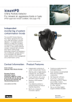
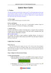
icountPDZ2
g icountPDZ2 User Manual
B.84.833_IPDZ2M_GB_Ver A
© 2010, Parker Hannifin Corporation
www.parkerhfde.com
g
Overview
Parker Hannifin’s IPD Z2 is an on-line laser particle detector. This mineral based hydraulic fluid
contamination detector is designed for use in ATEX category 3 areas and is housed in a stainless
steel IP69K approved enclosure.
The unit has two size 06L EO 24° cone-end hydraulic connections that allow the fluid to be
transferred through the unit for analysis. The electrical supply and communication is made via two
M12 Ultra Lock IP69K approved connectors.
Conditons for safe use
To ensure compliance with the certification, users are NOT permitted to open the unit
under any circumstances. Doing so will invalidate the unit’s calibration and it would NOT
be suitable for Hazardous area use.
2
Parker Hannifin icountPDZ2
g
Contents
Overview....................................................................................................2
Conditons for safe use...............................................................................2
Laser Information......................................................................................4
Declaration of Conformity and Certificate of Manufacture.......................4
Product identification label.......................................................................5
Introduction.............................................................................. 6
Principles of operation..............................................................................6
Benefits......................................................................................................7
Technical specification..............................................................................8
Software default settings..........................................................................9
Product features......................................................................................10
Dimensions for installation.....................................................................10
Connections............................................................................ 11
Hydraulic connection...............................................................................11
Flow control.............................................................................................12
System 20 sensor connection.................................................................13
Electrical connections.............................................................................14
Variable current output settings.............................................................19
Variable voltage output settings..............................................................20
CAN-bus output option............................................................................20
Moisture sensor output settings.............................................................20
Digital Display Unit connection...............................................................21
RS232 connection....................................................................................23
Software................................................................................. 24
icountPD Setup Utility software..............................................................24
Microsoft Windows® HyperTerminal connection....................................27
Communication protocol.........................................................................29
Reference............................................................................... 34
Optional wiring configuration..................................................................34
Optional Limit Relay hysteresis..............................................................34
Interpreting data......................................................................................36
ISO/NAS/SAE comparison chart.............................................................40
Component cleanliness guidelines.........................................................41
Viscosity charts........................................................................................42
ISO contamination charts........................................................................43
Ordering Information...............................................................................46
Parker Hannifin icountPDZ2
3
g
Laser Information
This product contains an invisible infrared 5mW laser.
Any dismantling of the product may result in dangerous exposure to laser radiation.
DANGER
INVISIBLE LASER RADIATION
WHEN OPEN. AVOID DIRECT
EXPOSURE TO BEAM.
CAUTION: Users are not required to access the laser radiation source and should
never do so.
Declaration of Conformity and Certificate of Manufacture
CE conformity
The IPD Z2 is in conformity with the protection requirements of the following European Standards in
English:
■■ Directive 94/9/EC of the European Parliament and the Council, for equipment intended for
use in potentially explosive atmospheres (ATEX).
■■ EN 60079-0:2009, Electrical apparatus for explosive gas atmospheres General requirements.
■■ EN 60079-15:2005, Electrical apparatus for explosive gas atmospheres – Construction, test
and marking of type of protection “n” electrical apparatus.
■■ EN 61241-1:2004, Electrical apparatus for use in the presence of combustible dust.
Protection by enclosures ”tD”
■■ IECEx 60079-0:2006 ed 4.0 (IECEx 60079-0:2007 ed 5.0) – Electrical equipment for
explosive gas atmospheres – Part 0: General requirements
■■ IECEx 60079-15 :2005 ed 3.0 – Electrical apparatus for explosive gas atmospheres – Part
15: Construction, test and marking of type of protection ”n” electrical apparatus
■■ IECEx 61241-1:2004 ed 1: IECEx Test Report for IEC 61241-1 (2004) ed 1.0 – Electrical
apparatus for use in the presence of combustible dust – Part 1: Protection by enclosures
“tD”
The Product(s) described above are in conformity with the essential requirements of the
following directives:
89/336/EEC amended by 92/31/EEC, 93/68/EEC and repealed by 2004/108/EEC
Harmonised standards:
EN61000-6-3:2007 Electromagnetic compatibility – Part 6-3: Generic standards – Emission
standard for residential, commercial and light-industrial environments.
EN61000-6-2:2005 Electromagnetic compatibility (EMC) – Part 6-2: Generic standards – Immunity
for industrial environments
4
Parker Hannifin icountPDZ2
g
Product identification label
The identification label attached to the enclosure (an example is given below) is explained in the
table that follows:
5
1
2
3
4
7
8
bk
bl
6
9
Item Field
1
2
3
Values
Part Number
icountPDZ2
D.O.M.
Date of manufacture
Serial Number
The serial number consists of eight digits, for example: GD6NN001
(‘GD’ is the month and year; ‘6NN’ is the product group; the last three digits
are entered sequentially through a month, reverting to ‘001’ at the beginning
of each month)
4
5
Manufactured
Country of manufacture (United Kingdom)
Name and address of
manufacturer
Parker Hannifin (UK) Ltd, Filter Division Europe,
Condition Monitoring Centre, Brunel Way,
Thetford, Norfolk, IP24 1HP, UK
6
ATEX certification number
Ex = European mark
II = Non-mining
3 = Equipment category (Zone 2/22)
GD = Type of explosive atmosphere (G = Gas, D = Dust)
7
ATEX/IECEx category 3
certificate coding (Gas)
Ex = Explosion protected
nA = Type ‘n’ (non-sparking)
IIC = Gas group
T4 = Temperature class (4 = maximum surface temperature of 135°C)
Gc = Equipment protection level (G = Gas, c = Zone 2)
8
ATEX/IECEx category 3
certificate coding (Dust)
Ex = Explosion protected
tc = Protection by enclosure
IIIC = Equipment grouping typical dust material
Dc = Equipment protection level (D = Dust, c = Zone 2)
9
CE Conformity marking and
number of notified body
responsible for audit production
CE 0518
bk
bl
Certificate Numbers
SIRA 09ATEX4340X IECEx SIR 09.0137X
Ambient operating temperature
Between -30°C and +60°C
Parker Hannifin icountPDZ2
5
g
Introduction
Introduction
Parker Hannifin’s icountPDZ2 represents the most up-to-date technology in solid particle
contamination analysis. The icountPDZ2 is a compact, permanently-mounted laser-based particle
detector module that provides a cost-effective solution to fluid management and contamination
control.
Principles of operation
The icountPDZ2 measures particle contamination continuously and updates the output options and
limit relay every second.
Unlike the Parker CM20, LCM20 or MCM20, the unit does not perform a ‘one-off’ test. This means
that even if the Measurement Period is set to 60 seconds, the output and limit relay all report the
presence of dirt in the oil in just a few seconds – it does not wait until the end of the Measurement
Period before reporting the result.
The icountPDZ2 has just one setting to control the accuracy, stability and sensitivity of the
measurements and that is the ‘Measurement Period’. This can be set from 5 seconds to 180
seconds. The longer the Measurement Period, the more contaminant is measured, averaging out
any spikes seen on a smaller sample. The shorter the Measurement Period, the more sensitive
the icountPDZ2 is to small slugs of contaminant, but it can also reduce the performance on clean
systems. Thus, the user can select how sensitive the icountPDZ2 is to spikes of contaminant, and
how quickly it responds to contamination levels above the set point (‘limits’).
With a Measurement Period of 100 seconds, the results will be for the last 100ml of oil that has
flowed through the icountPDZ2, updated on a second-by-second basis, giving an effectively
continuous readout of the level of contamination.
Calibration recommendations
NOTE: Any servicing or repair work must be carried out by a Parker ATEX approved
service centre. Contact your local Parker Hannifin Sales Company for recalibration details.
The recommended period between recalibration is 12 months.
Please refer to the Parker Hannifin Quality and Servicing booklet (FDCB272UK), supplied on CD.
6
Parker Hannifin icountPDZ2
g
Introduction
Benefits
■■ Independent monitoring of system contamination trends
■■ Calibration by recognised online principles confirmed by relevant International Organization
for Standardization (ISO) procedures
■■ Indicators for Low, Medium and High contamination levels
■■ A low cost solution to prolonging fluid life and reducing machine downtime
■■ Self-diagnostic software
■■ Mineral fluid-compatible construction
■■ Fully PC/PLC integration technology such as: RS232, 0–3V/0–5V, 4–20mA and CAN-bus
(SAE J1939) – see the ‘Product Configurator’, page 46, for communication options
■■ Percentage saturation reporting through an integrated moisture sensor – see the ‘Product
Configurator’ on page 46, for the moisture sensor option.
Parker Hannifin icountPDZ2
7
g
Introduction
Technical specification
Feature
Specification
Product start-up time
5 seconds minimum
Measurement period
5–180 seconds
Reporting interval
0–3600 seconds via RS232 communication
Principle of operation
Laser Diode optical detection of actual particulates
International codes
ISO 7 – 22, NAS 0 – 12
Calibration
By recognised online methods confirmed by the relevant ISO procedures.
MTD – Via a certified primary ISO 11171 automatic particle detector using ISO 11943
principles, with particle distribution reporting to ISO 4406:1996
ACFTD – Conforming to ISO 4402 principles with particle distribution reporting to ISO
4406:1996
Recalibration
Contact Parker Hannifin
Working pressure
2–420 bar (30–6000 PSI)
Flow range through
icountPDZ2
Note: Flow may be bi-directional
40–140 ml/min (optimum flow 60 ml/min)
(0.01 – 0.04 USGPM (optimum flow 0.016 USGPM))
Online flow range via System
20 sensors
Size 0 = 6 to 25 l/min (2–7 USGPM)
Size 1 = 24 to 100 l/min (6–26 USGPM)
Size 2 = 170 to 380 l/min (45–100 USGPM)
Ambient storage temperature
–40°C to +80°C (–40°F to +176°F)
Environment operating
temperature
-30°C to +60°C (–22°F to 140°F)
Fluid operating temperature
+5°C to +80°C (+41°F to 176°F)
Computer compatibility
Parker recommends the use of a 9-way D-type connector. This can be connected to
a USB port using a USB-serial adaptor. Note that these connectors/adaptors are NOT
supplied with icountPDZ2 units: contact Parker Hannifin for advice.
Moisture sensor calibration
±5% RH (over compensated temperature range of +10ºC to +80ºC; +50ºF to +176ºF)
Operating humidity range
5% RH to 100% RH
Moisture sensor stability
±0.2% RH typical at 50% RH in one year
Power requirement
Regulated 9–40Vdc
Current rating
Typically 120mA
Certification
IP69K rating
EC Declaration of Conformity (see page 4).
Analogue output options (specified when ordering)
Variable current
4–20mA
Variable voltage
0–5Vdc, 0–3Vdc (user selectable)
CAN-bus
to SAE J1939 (e.g. Parker IQAN)
Moisture sensor
Linear scale within the range 5% RH to 100% RH
8
Parker Hannifin icountPDZ2
g
Introduction
Software default settings
Standard defaults
Comms echo
OFF
Verbose errors
OFF
STI Sensors used
OFF
Reporting standards
ISO
Particle limits
19 / 18 / 15
Measurement period
60 seconds
Reporting interval
30 seconds
Power-on mode
AUTO
Auto start delay
5 seconds
Date format
dd/mm/yy
Default if options fitted
Relay hysteresis
ON
Relay operation for particle limits
ON
Relay operation for moisture sensor ON
limits
0–5V/0–3V output voltage range
0–5V
Moisture sensor limit
70%
Parker Hannifin icountPDZ2
9
g
Introduction
Product features
Four mounting
locations (two
each side) to suit
M8 (5/16”) fixings
(supplied)
Size 06L EO 24° cone end
hydraulic connections (Pipe
not supplied)
Supply and Limit relay
M12, 8-pin Ultra Lock IP69K
Rated Male connector. Supply /
Limit Cable, 5m (16ft 4in)
Product identification label
Communication cable
M12, 8-pin Ultra Lock
IP69K female connector.
Communication Cable, 5m
(16ft 4in)
Dimensions for installation
Dimensions are given in mm (inches)
Four mounting locations (two
each side) to suit M8 (5/16
inch) fixings, supplied. Flange
thickness is 2mm (5/64 inch)
10
Parker Hannifin icountPDZ2
g
Connections
Connections
Hydraulic connection
Our recommendation is to position the icountPDZ2 as close to the system output as possible whilst
controlling the flow to the optimum 60ml/min. This then provides the highest pressure conditions,
plus the oil in this position is indicative of the reservoir’s oil condition.
The IPDZ2 is supplied with two size 06L EO 24° cone-end hydraulic connections.
For hydraulic connection, ensure that the hydraulic/pipe connection fitting is compatible with the
size 06L EO 24° cone bulkhead fitting.
Assembling the EO nut fitting
Step
1
Press the tube-end firmly into the assembly
core.
Turn back the nut for easy tube insertion and fit
the nut hand tight, then tighten the fitting until
you feel a sharp increase in resistance.
2
Ensure the bulkhead fitting is held with a
17mm spanner and tighten (approximately 1 to
1½ turns).
3
Now remove the pipe and nut to check
assembly.
The gap between sealing ring and
retaining ring must be closed. A little
relaxation (approximately 0.2mm) is allowed.
If the gap is not closed: Check all
components, including the tube.
Parker Hannifin icountPDZ2
11
g
Connections
4
Assemble the fitting until wrench-tight (without
spanner extension).
Tighten the fitting firmly by a minimum 1/6
(max ¼) turn (i.e. 1 to 1½ flats)
Flow control
A pressure compensated, flow control device (Parker Hannifin
part number S840074) has been developed to give the
icountPDZ2 user greater flexibility. The flow control device
enables testing where flow ranges are outside the icountPDZ2
specifications (i.e. 40–140 ml/min), or where pipe diameters do
not allow the icountPDZ2 to be installed.
Required Differential Pressure Range 5–315 Bar
The flow control device fits onto the downstream (outlet) side of
the icountPDZ2, connecting through a manifold block via a selfsealing quick connection test point.
The differential pressure valve automatically compensates for
pressure and viscosity changes, whilst maintaining its flow
setting even as the workload changes.
The table below is used to select the appropriate valve position:
12
Valve position
cSt range
3
20–100
3.8
90–200
4.2
190–320
5
310–500
Parker Hannifin icountPDZ2
g
Connections
System 20 sensor connection
6 to 25 l/min (optimum flow = 15 l/min)
Size 1
24 to 100 l/min (optimum flow = 70 l/min)
Size 2
170 to 380 l/min (optimum flow = 250 l/min)
56
Size 0
Size 0 Sensor
Ø30
Online flow range via System 20 inline sensors:
The required differential pressure across inline sensors is
0.4 bar (minimum)
Refer to the ‘Sensor part numbers’ section on page 46
before ordering System 20 sensors.
Size 1 Sensor
Ø41
66.5
See ‘Inline Sensor Monitors’ (Parker Hannifin Brochure
CM013GB1) for more information on System 20 sensors.
95
137
Ø66.7
73.5
Size 2 Sensor
231.3
(All dimensions are in millimetres)
IMPORTANT NOTE: P1 and P2 of the System 20 sensors MUST be connected to the
icountPDZ2 test points. Ensure that the icountPDZ2 command ‘SSU’ is set to ‘Yes’
when connecting to icountPDZ2 – refer to ‘Communication protocol’ section of this
manual for a list of user commands.
Contact Parker Hannifin if you require further advice in connecting icountPDZ2 to your system.
Parker Hannifin icountPDZ2
13
g
Connections
Electrical connections
The M12 8-pin Ultra Lock connection system uses innovative push-to-lock technology to make a
quick but secure connection. The unique O-ring radial seal is operator-independent, so there is no
chance of over-tightening or under-tightening.
Supply and Limit Relay cable
Communication cable
M12, 8-pin Ultra Lock IP69K-rated,
male connector to unterminated 5m
(16ft 4in) Supply and Limit Relay
cable.
M12, 8-pin Ultra Lock IP69K-rated
female connector to unterminated
5m (16ft 4in) Communication cable.
IMPORTANT NOTE: The IP69K Ingress Protection is only valid when using the M12
Ultra Lock mating connector cable (supplied).
Connecting/Disconnecting
Ensure that the locating pin and slot are correctly aligned (to avoid damaging the pins) and push
home firmly to connect. To disconnect, pull the Ultra Lock’s metal collar back to release the cable
lock and pull the cable boot out squarely.
Wiring diagrams
Wiring diagrams are provided (on pages 16–17), showing how a digital multimeter may be
connected to the Communication cable and the Supply and Limit Relay cable, for both voltage and
current options. The connections for an optional moisture sensor (if fitted) are also shown.
A diagram for connecting the icountPDZ2 to an external CAN-bus network is given on page 18.
14
Parker Hannifin icountPDZ2
g
Connections
Communication cable connector
�
�
�
�
�
�
Pin configuration diagram
M12, 8-pin Ultra Lock IP96K female connector, end view
�
�
Pin number
No options fitted
(Wire colour
recommended)
4–20mA option fitted
0–5V/0–3V option fitted
CAN-bus option fitted
1 (White)
NOT USED
Channel C, ISO 14µm(c)
Channel C, ISO 14µm(c)
NOT USED
2 (Brown)
RS232 Ground (* Pin 5)
RS232 Ground (* Pin 5)
RS232 Ground (* Pin 5)
RS232 Ground (* Pin 5)
3 (Green)
NOT USED
Channel A, ISO 4µm(c)
Channel A, ISO 4µm(c)
CAN+ (Hi)
4 (Yellow)
NOT USED
Channel B, ISO 6µm(c)
or NAS (if selected)
Channel B, ISO 6µm(c)
or NAS (if selected)
CAN– (Lo)
5 (Grey)
RS232 Receive (* Pin 3)
RS232 Receive (* Pin 3)
RS232 Receive (* Pin 3)
RS232 Receive (* Pin 3)
6 (Pink)
RS232 Transmit (* Pin 2)
RS232 Transmit (* Pin 2)
RS232 Transmit (* Pin 2)
RS232 Transmit (* Pin 2)
7 (Blue)
NOT USED
Moisture sensor channel (if
fitted)
Moisture sensor channel (if
fitted)
CAN Ground
8 (Red)
NOT USED
NOT USED
NOT USED
NOT USED
* Parker Hannifin recommends the use of a 9-way D-type socket with RS232, using the
pin configurations given in the above table.
NOTE: If the moisture sensor is fitted without the 4–20mA or the 0–5V/0–3V option, then
the output is via RS232.
Supply and Limit relay cable connector
�
�
�
Pin configuration diagram
M12, 8-pin Ultra Lock IP69K-rated, male connector, end view
�
�
�
�
�
Pin number
No options fitted
(Wire colour
recommended)
4–20mA option fitted
0–5V/0–3V option fitted
CAN-bus option fitted
1 (White)
Relay Normally Closed (if
fitted)
Relay Normally Closed (if
fitted)
Relay Normally Closed (if
fitted)
NOT USED
2 (Brown)
NOT USED
4–20mA Supply 12–20Vdc
0–5 / 0–3V Supply
12–24Vdc
NOT USED
3 (Green)
Relay Common (if fitted)
Relay Common (if fitted)
Relay Common (if fitted)
NOT USED
4 (Yellow)
Relay Normally Open (if fitted) Relay Normally Open (if fitted) Relay Normally Open (if fitted) NOT USED
5 (Grey)
NOT USED
NOT USED
NOT USED
NOT USED
6 (Pink)
NOT USED
NOT USED
0–5V / 0–3V Supply 0 Vdc
NOT USED
7 (Blue)
Product supply 0Vdc
Product supply 0Vdc
Product supply 0Vdc
Product supply 0Vdc
8 (Red)
Product supply 9–40Vdc
Product supply 9–40Vdc
Product supply 9–40Vdc
Product supply 9–40Vdc
IMPORTANT NOTE: It is the responsibility of the end user to ensure that the cable’s
braided screen is terminated to a suitable earth bonding point.
Parker Hannifin icountPDZ2
15
16
Supply 0Vdc–
PSU
PSU
pin 2
pin 3
pin 4
pin 5
pin 6
pin 7
pin 8
pin 2
pin 3
pin 4
pin 5
pin 6
pin 7
pin 8
Digital multimeter or similar
Moisture sensor channel
(0–5V/0–3V) output (if fitted) (Blue)
Channel B (0–5V/0–3V) output (Yellow)
Channel A (0–5V/0–3V) output (Green)
Channel C (0–5V/0–3V) output (White)
B
A
Optional switch box
C
ms
(This example shows the
switch position set to
monitor Channel A)
pin 1
Comms
cable
pin 1
****V
Product supply
9–40Vdc+ (Red)
Product supply 0Vdc– (Blue)
0–5V/0–3V supply 0V– (Pink)
0–5V/0–3V supply 12–24V+ (Brown)
Supply
cable
icountPDZ2
Connections
g
M12, 8-pin connector: 0–5V/0–3V voltage measurement
Parker Hannifin icountPDZ2
Parker Hannifin icountPDZ2
4–20mA supply 0Vdc
PSU
Note that the
4–20mA DC
supply must be
a separate and
dedicated circuit.
PSU
pin 2
pin 3
pin 4
pin 5
pin 6
pin 7
pin 8
pin 2
pin 3
pin 4
pin 5
pin 6
pin 7
pin 8
Moisture sensor channel
(4–20mA) output (if fitted) (Blue)
Channel B (4–20mA) output (Yellow)
Channel A (4–20mA) output (Green)
Channel C (4–20mA) output (White)
A
Optional switch box
C
B
ms
(This example shows the
switch position set to
monitor Channel A)
pin 1
Comms
cable
pin 1
Digital multimeter or similar
****mA
Product supply 9–40Vdc+
(Red)
Product supply 0Vdc– (Blue)
4–20mA supply 12–20Vdc+ (Brown)
Supply
cable
icountPDZ2
g
Connections
M12, 8-pin connector: 4–20mA current measurement
17
g
Connections
CAN-bus (SAE J1939) connections
icountPDZ2
Supply
cable
Product supply 0Vdc– (Blue)
Comms
cable
pin 1
pin 1
pin 2
pin 2
pin 3
pin 3
pin 4
pin 4
pin 5
pin 5
pin 6
pin 6
pin 7
pin 7
pin 8
pin 8
CAN Hi (Green)
CAN Lo (Yellow)
CAN ground (Blue)
Product supply 9–40Vdc+
(Red)
CAN ground
CAN controller
(e.g. Parker IQAN)
18
CAN Lo
CAN Hi
Parker Hannifin icountPDZ2
g
Connections
Variable current output settings
ISO setting
The following table can be used to relate an analogue output (in mA) to an ISO code. For example,
an output of 10mA is equal to an ISO code 12.
mA
4.0
4.5
5.0
5.5
6.0
6.5
7.0
7.5
8.0
8.5
9.0
9.5
10.0
10.5
11.0
11.5
12.0
ISO
0
1
2
3
4
5
6
7
8
9
10
11
12
13
14
15
16
mA
12.5
13.0
13.5
14.0
14.5
15.0
15.5
16.0
16.5
17.0
17.5
18.0
18.5
19.0
19.5
20
ISO
17
18
19
20
21
22
*
*
*
*
*
*
*
cont.
Over-range
ERROR
ISO v output mA
The actual calculation is as
follows:
ISO code = (output in mA – 4) x 2
output mA
e.g. (11.5mA – 4) x 2 =
7.5 x 2 = ISO 15
* = Saturation (i.e. above ISO
code 22)
ISO code
NAS setting
The following table can be used to relate an analogue output (in mA) to a NAS code. For example,
an output of 15mA is equal to NAS code 10.
mA
4
5
6
7
8
9
10
11
12
13
14
15
16
17
18
19
20
NAS
00
0
1
2
3
4
5
6
7
8
9
10
11
12
*
*
ERROR
Note: * = Saturation (above NAS code 12)
NAS v. output mA
The actual calculation is as
follows:
NAS code = (output in mA – 5)
output mA
e.g. 15mA – 5 = NAS 10
* = Saturation (i.e. above NAS
code 12)
NAS code
Parker Hannifin icountPDZ2
19
g
Connections
Variable voltage output settings
The variable voltage output option is capable of two different voltage ranges: a 0–5Vdc range as
standard, and a user-selectable 0–3Vdc range. The ‘Full list of commands’ section of this manual
(page 30–32) gives information on how to change the voltage output range.
The following tables can be used to relate the analogue output to an ISO or NAS code.
For example, in a 0–5Vdc range, ISO code 16 is equal to an output of 3.5Vdc. In a 0–3Vdc range,
ISO code 8 is equal to an output of 1.0Vdc.
Table relating ISO codes to Voltage output
ISO
Err
0
1
2
3
4
5
6
7
8
9
10
11
0–5Vdc
<0.2
0.3
0.5
0.7
0.9
1.1
1.3
1.5
1.7
1.9
2.1
2.3
2.5
0–3Vdc
<0.15
0.2
0.3
0.4
0.5
0.6
0.7
0.8
0.9
1.0
1.1
1.2
1.3
cont.
ISO
12
13
14
15
16
17
18
19
20
21
22
0–5Vdc
2.7
2.9
3.1
3.3
3.5
3.7
3.9
4.1
4.3
4.5
4.7
>4.8
0–3Vdc
1.4
1.5
1.6
1.7
1.8
1.9
2.0
2.1
2.2
2.3
2.4
>2.45
Err
Table relating NAS codes to Voltage output
NAS
Err
00
0
1
2
3
4
5
6
7
8
9
10
11
12
Err
0–5Vdc
<0.4
0.6
0.9
1.2
1.5
1.8
2.1
2.4
2.7
3.0
3.3
3.6
3.9
4.2
4.5
>4.6
0–3Vdc
<0.2
N.S.
0.3
0.5
0.7
0.9
1.1
1.3
1.5
1.7
1.9
2.1
2.3
2.5
2.7
>2.8
(N.S. = Not Supported)
CAN-bus output option
If you plan to use the icountPDZ2 with a CAN-bus (SAE J1939) network, you can order this output
option when specifying the unit. Refer to the ‘Product configurator’ (page 46) in the Reference
section of this manual. The CAN option provides an interface to external CAN-bus networked
systems – for example, to the Parker IQAN.
Moisture sensor output settings
The Moisture sensor is an option that can be included when specifying the icountPDZ2. Refer to the
‘Product configurator’ (page 46) in the Reference section of this manual.
The Moisture sensor reports on the saturation levels of the fluid passing through the icountPDZ2
sensing cell. The output is a linear scale, reporting within the range of 5% saturation to 100%
saturation.
Table relating Saturation levels in the sensing cell to icountPDZ2 outputs
20
Saturation
4–20mA
0–3Vdc
0–5Vdc
5%
4.8
0.15
0.25
25%
8
0.75
1.25
50%
12
1.50
2.50
75%
16
2.25
3.75
100%
20
3.00
5.00
Parker Hannifin icountPDZ2
g
Connections
Digital Display Unit connection
icountPDZ2
Supply
cable
pin 1
pin 2
pin 3
pin 4
pin 5
pin 6
pin 7
pin 8
Comms
cable
pin 1
pin 2
pin 3
pin 4
pin 5
pin 6
pin 7
pin 8
Digital Display Units
(e.g. Parker Hannifin DDU1002)
Output channel C
Output channel A
Output channel B
Moisture sensor (if fitted)
External 12–20Vdc
power supply
The above diagram shows how a set of Parker Hannifin DDUs can be used to display Channels A,
B and C, plus the Moisture sensor (if fitted).
Digital Display Units available
Part number
Description
DDU1001
Process indicator, 22–55Vdc
DDU1002
Process indicator, 90–264Vdc
Parker Hannifin icountPDZ2
21
g
Connections
icountPDZ2
Supply
cable
pin 1
pin 2
pin 3
pin 4
pin 5
pin 6
pin 7
pin 8
Comms
cable
pin 1
pin 2
pin 3
pin 4
pin 5
pin 6
pin 7
pin 8
Output channel C
Output channel A
Output channel B
Moisture sensor (if fitted)
External 12–20Vdc
power supply
ms
B
Digital Display Unit
(e.g. Parker Hannifin DDU1002)
A
C
The above diagram shows how a single DDU can be used to display Channels A, B and C, plus the
Moisture sensor (if fitted), by using a switch to display each channel in turn.
22
Parker Hannifin icountPDZ2
g
Connections
RS232 connection
Communication can be established between icountPDZ2 and a PC using an RS232 serial
connection with the Parker Utility Setup Tool, the Parker Terminal utility, or via Microsoft Windows®
HyperTerminal.
Please note that HyperTerminal is not supplied with Windows Vista™, but the Parker Utility Setup
Tool and Parker Terminal can be used with this operating system. Both Parker programs are
supplied on the icountPD CD.
PC connection
The RS232 wires need to be connected to a 9-way D-type connector (not supplied as standard).
For the connector pin termination and wire colour, refer to the ‘Communication cable connector’
section of this manual (page 15).
The device can then be either connected direct to PC serial port (Figure 1) or connected via an
RS232-to-USB adaptor cable (Figure 2).
An RS232 to USB convertor can be supplied by Parker Hannifin (part number ACC6NN017).
9-way D-type serial port on
PC
Recommended 9-way D-type
socket (icountPDZ2 Comms
cable)
USB connector to PC/
laptop
RS232-to-USB adapter
cable
Figure 1
Figure 2
NOTE: The 9-way D-type connector, RS232-to-USB adaptor cable and installation
software are not supplied as standard with the icountPDZ2.
Parker Hannifin icountPDZ2
23
g
Software
Software
The icountPDZ2 may be configured using the icountPD Setup Utility, supplied on CD.
For more direct control of the device using its communications protocol, you may use the Parker
Terminal program: both Parker programs are supplied on the icountPDZ2 CD. You may also use
Microsoft Windows® HyperTerminal program, but note that this program is not currently supplied
with the Windows Vista™ operating system.
icountPD Setup Utility software
PC Installation
The icountPD Setup Utility and Parker Terminal software is available on the CD supplied with the
icountPDZ2. The software can be run directly from the CD or copied to a PC hard drive.
Using the icountPD Setup Utility
Check that the icountPDZ2 is connected to power and the communication cable is connected to
the PC via the RS232 plug.
Place the CD in your PC drive and wait for the selection screen to appear. On starting the software,
the icountPD Setup Utility screen appears.
Step 1A:
With the icountPDZ2 connected to
power and the RS232 connected
to the PC, select the appropriate
communication port.
Step 1B:
Note the status of the icountPDZ2.
24
Parker Hannifin icountPDZ2
g
Software
Step 2:
Set the values for ‘Detector ID’
and ‘Date Format’.
The remaining detector
information is preset by Parker
Hannifin and cannot be changed.
Step 3:
Set the values in ‘Measurement
Configuration’, ‘Relay Options’
and ‘Alarm Limits’.
Step 4:
Set the Voltage Range (0–5V, 0–3V
or J1939) in ‘Output Options’
according to the options fitted.
Parker Hannifin icountPDZ2
25
g
Software
Step 5:
Setup values are verified as valid
in ‘Results’.
Click ‘Start’ to start verification
and ‘Stop’ to stop.
26
Parker Hannifin icountPDZ2
g
Software
Microsoft Windows® HyperTerminal connection
An alternative way of achieving communication with icountPDZ2 is to use the HyperTerminal
program supplied with Microsoft Windows (but not always installed on the PC or laptop’s hard
disk – check the installation disk, or contact your organisation’s IT department if the program is
not present). Please note that HyperTerminal is not supplied with Windows Vista™, but the
Parker Terminal utility can be used with this operating system.
The standard communication settings (used in STEP 4) are as follows:
Baud Rate
9600
Data bits
8
Parity
None
Stop bits
1
Flowcontrol
None
Step 2:
Select ‘HyperTerminal’.
(from All Programs
4 Accessories
4 Communications
4 HyperTerminal)
Step 1:
Click ‘Start’
Step 3:
Click and type the connection
name you wish to use to identify
this session
Parker Hannifin icountPDZ2
27
g
Software
Step 4:
Select the appropriate USB port.
Step 5:
Enter the communication
settings (as in the ‘standard
communications settings’ table,
on the previous page).
Step 6:
Once the icountPDZ2 is
connected to power, the product
identification is displayed.
This confirms that communication
to icountPDZ2 has been
established and the unit is now
ready for operation.
28
Parker Hannifin icountPDZ2
g
Software
Communication protocol
The commands used with the icountPDZ2 are either made up of Set, Read or Start/Stop
commands.
■■ Set commands allow the value or values of parameters to be changed
■■ Read commands allow the value or values of parameters to be read
■■ Start/Stop commands allow the user to start and stop tests.
Example:
[SDF dd/mm/yy] sets the date format
[RDF] reads the product format date
All commands are sent in ASCII characters, and the protocol accepts both upper and lower case
characters. For example, all of the following codes are equivalent:
SDF = Sdf = SDf = sdF = sdf
NOTE: The use of a ‘=’ after a command, for example [SDF = dd/mm/yy], is optional.
Certain commands are for expert use only and can be accessed via a password system. Should an
unauthorized person attempt to access these commands the icountPDZ2 returns the error code for
‘Invalid Command’.
A list of error codes is given on page 33.
Most-used commands
Common User Read commands
Command
Description
icountPDZ2 response
RDU
Read calibration dust
Calibration dust displayed (i.e. MTD
or ACFTD)
RLT
Read NAS or ISO limits
Limits displayed
RRS
Read reporting standard
ISO or NAS displayed
Common User Set commands
Command
Description
User response
SLT
Set limits
i.e. ‘SLT 19 18 15’
SLT ## ## ## (for ISO)
SLT ## (for NAS)
SRS
Set reporting standard
SRS iso
SRS nas
SRI
Set reporting interval
0 to 3600 seconds
0 = No reporting
SRI ####
NOTE: The reporting interval (SRI) controls how often the icountPDZ2 sends results over
the RS232.
User Start/Stop commands
Command
Description
Response
STR or START
Start testing
‘OK’ displayed
STP or STOP
Stop testing
‘OK’ displayed
Parker Hannifin icountPDZ2
29
g
Software
Full list of commands
User Read Commands
Command
Description
icountPDZ2 response
RCD
Read the last Calibration Date
Last calibration date displayed
RCE
Read Communication Echo
‘ON’ or ‘OFF’ displayed
Comms Echo ON allows the icountPDZ2 to communicate in two directions
(Hyperterminal)
Comms Echo OFF allows the icountPDZ2 to communicate in one direction (Setup
Utility)
RDD
Read the next calibration Due Date
Next calibration due date displayed
RDF
Read Date Format
Date format displayed (e.g. dd/mm/yy)
RDI
Read Detector ID
Detector ID displayed
RDS
Read Detector Status
IPD status displayed (e.g. RUNNING)
RDU
Read the calibration Dust Unit
Calibration dust displayed (i.e. MTD or
ACFTD)
REN
Read last Error Number
Last error number displayed
RER
Read last Error text Report
Last error text displayed
REV
Read the Error Verbose mode
Error verbose mode displayed
Error Verbose ON displays the full description of the error code (i.e. Error 40 –
expected On or Off)
Error Verbose OFF displays just the error code (i.e. Error 40)
30
RFN
Read Fault Number
Fault number displayed
RJE
Read J1939 Status
‘ON’ or ‘OFF’ displayed
RLR
Read the Last contamination Result
Last contamination result displayed
RLT
Read contamination Limit Threshold
Contamination limits displayed
RML
Read Moisture sensor Limit
Moisture limit displayed
RMP
Read Measurement Period
RMV
Read the last Moisture sensor Value
ROF
Read Options Fitted
ROF = ABCDEFGHIJ
(see list of options below)
RON
Read Option Name
List of options
A = Alarm relay option
B = LED display option
C = OLED display option
D = Moisture sensor option
E = 4–20mA current loop option
F = 0–3/0–5V option
G = J1939 option
H = reserved
I = reserved
J = reserved
RPD
Read the Power on hold-off Delay
Power hold-off delay displayed
RPI
Read Product Identifier
icountPDZ2 displayed
RPM
Read the Power on Mode
‘AUTO’ or ‘MANUAL’ displayed
RPN
Read the icountPDZ2 Part Number
Parker part number displayed
RPT
Read Product Type
IPDH
RPV
Read Protocol Version
Protocol version displayed
RRI
Read Reporting Interval
Reporting interval displayed
RRS
Read Reporting Standard
‘ISO’ or ‘NAS’ displayed
RSB
Read Software Build number
RSH
Read limit relay Switch Hysteresis
RSL
Read Standards List
1
Measurement period displayed
1
Last moisture result displayed
Software build number displayed
2
‘ON’ or ‘OFF’ displayed
ISO, NAS
Parker Hannifin icountPDZ2
g
Software
RSN
Read Serial Number
RSS
Read limit relay Switch State
RSU
Read STI Sensor Used
‘YES’ or ‘NO’ displayed
RSV
Read Software Version displayed
Software version displayed
RVM
Read the Voltage Maximum range 3
Voltage range displayed
RWC
Read Warning limit relay for
Contamination 2
‘ON’ or ‘OFF’ displayed
RWM
1
2
3
Serial number displayed
2
‘ON’ or ‘OFF’ displayed
Read Warning limit relay for Moisture 1,2
‘ON’ or ‘OFF’ displayed
Command requires a Moisture Sensor to be fitted to icountPDZ2
Command requires a Limit Relay to be fitted to icountPDZ2
Command requires a 0–5V option to be fitted to icountPDZ2
User Set Commands
Command
Description
icountPDZ2 response
SCE
Set Communication Echo
SCE on
SCE off
Comms Echo ON allows icountPDZ2 to communicate in two directions
(Hyperterminal)
Comms Echo OFF allows icountPDZ2 to communicate in one direction (Setup
Utility)
SDF
Set Date Format
SDF dd/mm/yy
SDF mm/dd/yy
SDF yy/mm/dd
SDI
Set Detector ID
SDI ##############
(14 characters maximum, spaces not
allowed)
SEV
Set the Error Verbose mode
SEV on
SEV off
Error Verbose ON displays the full description of the error code (i.e. Error 40 –
Expected On or Off)
Error Verbose OFF displays just the error code (i.e. Error 40)
SJE
Set J1939 Status
SJE On/Off (can only set On)
SLT
Set contamination Limit Threshold
SLT ## ## ## (for ISO)
SLT ## (for NAS)
SML
Set Moisture sensor Limit 1
SML ###
SMP
Set Measurement Period
SMP ###
(### = 5 to 180 seconds)
The Measurement period sets the number of seconds the detector uses to
determine the contamination levels. So if this is 60 seconds, the unit will use the
last 60 seconds of oil to determine the contamination level. (See the ‘Component
cleanliness guideline’ chart in the Reference section of this manual.)
SPD
Set the Power on hold-off Delay
SPD ###
(### = 0 to 900 seconds)
The Power-on hold-off delay command allows the user to delay the start of the
icountPDZ2 operation.
SPM
Set the Power on Mode
SPM auto
SPM manual
With the Power-on Mode set to ‘Auto’ icountPDZ2 starts testing automatically when
the power is connected using the last setup parameters. With the Power-on Mode
set to ‘Manual’ icountPDZ2 becomes idle and requires the user to manually start
testing.
SRI
Set Reporting Interval
SRI mm:ss
(0 to 3600 seconds (i.e. 0–1 hour); note
that 0 = No reporting)
The Reporting Interval controls how often icountPDZ2 sends results over the RS232
Parker Hannifin icountPDZ2
31
g
Software
SRS
Set Reporting Standard
SRS iso
SRS nas
SSH
Set limit relay Switch Hysteresis 2
SSH on
SSH off
SSS
Set limit relay Switch State 2
SSS on
SSS off
SSU
Set STI Sensor Used
SSU yes
SSU no
SVM
Set the Voltage Maximum range 3
SVM #
(3 = 0–3Vdc output
5 = 0–5Vdc output)
SWC
Set Warning limit relay for Contamination
SWC on
SWC off
2, 4
Set Warning limit relay for Moisture 1, 2, 4
SWM
32
SWM on
SWM off
1
Command requires a Moisture sensor to be fitted to the icountPDZ2
2
Command requires a Limit Relay to be fitted to the icountPDZ2
3
Command requires a 0–5Vdc option to be fitted to the icountPDZ2
4
If the Limit Relay has been turned OFF for both Contamination monitoring and
Moisture sensing, the Limit Relay will not operate, but the alarm status is not
affected.
If the Limit Relay has been turned ON for both Contamination monitoring and
Moisture sensing, the Limit Relay will operate when any alarm condition is reached.
Parker Hannifin icountPDZ2
g
Software
Error codes
If a command does not follow the protocol, an explanatory error code is returned.
Depending on the setting of SEV (Set the Error Verbose mode), either the error code, or the error
code and message are displayed.
For example, with SEV OFF (Error Verbose off) just the error code (e.g. Error 40) is returned. With
SEV ON (i.e. Error Verbose on) both the error code and message (e.g. Error 40 - Expected On or
Off) are returned.
Messages corresponding to the error codes are given in the following table:
Code
Message
Error 0
No error
Error 1
Unknown command
Error 2
Characters after command ignored
Error 3
Command ignored – unit is busy
Error 5
Unexpected character found
Error 6
Symbol too long
Error 7
Bad command format
Error 8
Unknown value
Error 9
Invalid date format
Error 10
Invalid date
Error 13
Option not fitted
Error 14
String too short
Error 15
String too long
Error 17
No test result
Error 18
Number expected
Error 19
Number too long
Error 20
Number out of range
Error 30
Interval shorter than duration
Error 40
Expected On or Off
Error 41
Expected Disabled or Enabled
Error 43
Expected Auto or Manual
Error 45
Expected Yes or No
Parker Hannifin icountPDZ2
33
g
Reference
Reference
Optional wiring configuration
Supply and Limit Relay cable wiring configuration
The icountPDZ2 can be specified to include a built-in limit switch relay which can be triggered when
a preset alarm level is reached. The relay contacts can be used to switch an external device on or
off.
These wires within the icountPDZ2 Supply and Limit Relay cable may be identified by their colour:
Yellow, White and Green, and are connected according to the diagram below.
Wire colour
Description
Yellow
Normally Open
White
Normally Closed
Green
Common
��
��
�
The contact rating is 5A at 5–24Vdc
IMPORTANT NOTE: It is the responsibility of the end user to ensure that the cable’s
braided screen is terminated.
Optional Limit Relay hysteresis
Hysteresis is a property of systems (usually physical systems) that do not instantly follow the forces
applied to them, but react slowly, or do not return completely to their original state.
To set Relay Limits, refer to the ‘Communication Protocol – User Commands’ section in this manual.
Hysteresis feature ON
The relay will energise when any channel is one code above the set limit and will only de-energize
when all channels are one code below the set limit.
Hysteresis feature OFF
The relay will energise when any channel is one code above the set limit and will only de-energize
when all channels are on the set limit.
34
Parker Hannifin icountPDZ2
g
Reference
Example ISO scenario
An icountPDZ2 has been connected to a hydraulic fluid transfer system. With the icountPDZ2 limit
relay switched off (Normally Closed), the limits set to ISO 20/18/13 and the relay cable electrically
connected to a Parker 10MFP Filtration Trolley. The icountPDZ2 will activate the 10MFP as soon as
the set limits are breached. The ten test results below show the effect of having the hysteresis on or
off:
Hysteresis feature ON
10MFP Trolley status
Test 1 result – 20/16/13
OFF
OFF
Test 2 result – 21/16/13
ON
Test 3 result – 20/16/13
ON
Test 4 result – 18/17/14
ON
Test 5 result – 18/16/13
ON
Test 6 result – 17/16/11
ON
Test 7 result – 17/16/11
OFF
Test 8 result – 18/17/13
OFF
Hysteresis feature OFF
10MFP Trolley status
ON
OFF
ON
OFF
ON
OFF
OFF
Test 9 result – 19/17/14
ON
Test 10 result – 19/17/13
ON
ON
OFF
ON = Relay activated, OFF = Relay not activated
NOTE: Electrical connection to a 10MFP Filtration Trolley requires the use of a relay
Example NAS scenario
An icountPDZ2 has been connected to a hydraulic system on a wind turbine. The icountPDZ2 limit
relay is switched off (Normally Closed), the limits set to NAS 9 and the relay cable is connected to a
Parker Guardian Filtration Unit. The icountPDZ2 activates the Guardian Filtration Unit as soon as the
set limit is breached. The ten test results below show the effect of having the hysteresis on or off:
Hysteresis feature ON
Guardian Unit status
Hysteresis feature OFF
Guardian Unit status
Test 1 result = 9
OFF
OFF
Test 2 result = 9
OFF
OFF
Test 3 result = 10
ON
Test 4 result = 9
ON
Test 5 result = 10
ON
ON
OFF
ON
Test 6 result = 8
OFF
OFF
Test 7 result = 7
OFF
OFF
Test 8 result = 10
ON
Test 9 result = 9
ON
Test 10 result = 10
ON
ON
OFF
ON
ON = Relay activated, OFF = Relay not activated
NOTE: Electrical connection to a Guardian Filtration unit requires the use of a relay
Parker Hannifin icountPDZ2
35
g
Reference
Interpreting data
The ISO code number corresponds to contamination
levels pertaining to three sizes.
The first scale number represents the number of particles
larger than 4µm(c) per 100 millilitre of fluid, the second
number for particles larger than 6µm(c) per 100 milllilitre of
fluid and the third number for particles larger than 14µm(c)
per 100 millilitre of fluid.
���
��
�
��
��
�
��
�
��
�
��
Number of particles per 100 millilitres greater than indicated size
Solid contaminants in fluid power systems vary in size,
shape, form and quantity. The most harmful contaminants
are normally between 6 microns and 14 microns. The
ISO code is the preferred method of reporting quantity of
contaminants.
�
��
��
�
��
���
�
��
��
��
���
��
���
��
���
�
��
��
���
��
�
��
�
��
�
��
�
��
��
�
�
���
�
��
�
���
�
���
�
���
��
�
���
�
�
�
�
�
�
�
�
�
�
��
��
��
Particle size, µm
Note that interpolation (i.e. estimation within the measured
range) is acceptable; extrapolation (i.e. estimation outside
of the measured range) is not.
36
Parker Hannifin icountPDZ2
g
Reference
ISO contamination numbers
Range
number
24
23
22
21
20
19
18
17
16
15
14
13
12
11
10
9
8
7
6
5
4
3
2
1
Number of particles per 100ml
More than
8 × 10⁶
4 × 10⁶
2 × 10⁶
1 × 10⁶
500 × 103
250 × 103
130 × 103
64 × 103
32 × 103
16 × 103
8 × 10³
4 × 10³
2 × 10³
1 × 10³
500
250
130
64
32
16
8
4
2
1
Up to and
including
16 × 106
8 × 10⁶
4 × 10⁶
2 × 10⁶
1 × 10⁶
500 × 103
250 × 103
130 × 103
64 × 103
32 × 103
16 × 103
8 × 10³
4 × 10³
2 × 10³
1 × 10³
500
250
130
64
32
16
8
4
2
For example: code 20/18/13 indicates that there are between 500,000 and 1,000,000 particles
larger than 2 microns, and between 130,000 and 250,000 particles larger than 5 microns, and
between 4000 and 8000 particles larger than 15 microns.
Reference ISO 4406:1999
When the raw data in one of the size ranges results in a particle count of fewer than 20 particles, the
scale number for that size range is labelled with the symbol ‘>’.
For example, a code of 14/12/>7 signifies that there are more than 8,000 and up to and including
16,000 particles equal to or larger then 4µm (c) per 100 ml and more than 2,000 and up to and
including 4,000 particles equal to or larger than 6µm (c) per 100 ml. The third part of the code, >7
indicates that there are more than 64 and up to and including 130 particles equal to or larger than
14µm (c) per 100 ml. But the 14µm (c) part of the code could actually be 7, indicating a particle
count more than 130 particles per 100 ml.
Parker Hannifin icountPDZ2
37
g
Reference
ISO4406 particle distribution chart
The chart includes various ISO level contamination grades
�������
�
�
�
�
��
��
�
��
�
Number of particles per 100ml greater than indicated size
��
�
�
�
��
�
��
��
��
��
�
�
�
�
���������
��
�
�
�
��
�
�
���������
���������
���������
�
�
�
�
�
��
���������
�
�
�
�
�
�
��
���������
��
�
��
�
��
��
�
��
�
��
��
�
�
�
�
��
�
��
��
�
��
�
��
�
�
�
�
��
��
�
�
�
�
Number of particles per ml greater than indicated size
��
�
�
��
��
��
��
��
��
��
particle size µm
38
Parker Hannifin icountPDZ2
g
Reference
NAS 1638 chart
5–15
15–25
25–50
50–100
>100
00
125
22
4
1
0
0
250
44
8
2
0
Classes (based on maximum contamination
limits, particles per 100ml)
Size range µm
Parker Hannifin icountPDZ2
1
500
89
16
3
1
2
1000
178
32
6
1
3
2000
356
63
11
2
4
4000
712
126
22
4
5
8000
1425
253
45
8
6
16,000
2850
506
90
16
7
32,000
5700
1012
180
32
8
64,000
11,400
2025
360
64
9
128,000
22,800
4050
720
128
10
256,000
45,600
8100
1440
256
11
512,000
91,000
16,200
2880
512
12
1,024,000
182,400
32,400
5760
1024
39
g
Reference
ISO/NAS/SAE comparison chart
BS 5540/4
Defence Std. 05/42
Table A
NAS 1638
SAE 749
Table B
11/8
2
12/9
3
0
13/10
4
1
5
2
6
3
7
4
8
5
9
6
14/9
400F
14/11
15/9
400
15/10
800F
15/12
16/10
800
16/11
1300F
16/13
17/11
1300
2000
17/14
18/12
2000
18/13
4400F
18/15
19/13
4400
19/16
20/13
10
6300
20/17
21/14
6300F
11
15,000
21/18
12
22/15
21,000
23/17
100,000
The above comparisons relate to particle count data only. To confirm to any particular standard,
reference should be made to the recommended experimental procedure.
40
Parker Hannifin icountPDZ2
g
Reference
Component cleanliness guidelines
Suggested acceptable contamination levels for various hydraulic systems.
Target
contamination
class to ISO 4406
Suggested
maximum particle
level
Sensitivity
Type of system
Typical components
6µm
14µm
6µm
14µm
13
9
4000
250
15
11
16,000
1,000
Critical
High performance servo and
high pressure long life systems,
e.g. aircraft, machine tools etc.
Industrial servovalves
16
13
32,000
4,000
Very
important
High quality reliable systems.
General machine requirements.
Piston pumps,
proportional valves,
compensated flow
controls
18
14
130,000
8,000
Important
General machinery and mobile
systems. Medium pressure,
medium capacity.
Vane pumps, spool
valves
19
15
250,000
16,000
Average
Low pressure heavy industrial
systems, or applications where
long life is not critical.
Gear pumps, manual
and poppet valves,
cylinders
21
17
1,000,000
64,000
Main
protection
Low pressure systems with large
clearances.
Ram pumps
Parker Hannifin icountPDZ2
Super critical Silt-sensitive control system with
very high reliability. Laboratory or
aerospace.
High performance
servovalves
41
g
Reference
Viscosity charts
The following charts indicate the differential pressure required to run a successful test at the
appropriate flow rates.
Example: If the fluid you wish to analyse has a relative viscosity to 60 cSt, to generate the optimum
flow rate 60ml/min a differential pressure of 0.5bar is required.
If the fluid you wish to analyse has a relative viscosity of 400 cSt, a 4 bar differential pressure would
result in 130 ml/min.
Differential pressure (bar)
Flow x Differential pressure x Viscosity
Flow rate (ml/min)
Differential pressure (bar)
Flow x Differential pressure
Flow rate (ml/min)
42
Parker Hannifin icountPDZ2
g
Reference
ISO contamination charts
Typical system applications and code numbers
These typical applications and ISO code numbers are taken from the UK Contamination and Control
Research Programme (1980–1984).
Ref. AHEM Guide to Contamination Control in Hydraulic Power Systems – 1985
Solid contaminant code No
13/10
�������
����
Application: Aircraft test stands
����
�
�
�
����
�
�
�
�� �
�
�
�
�
����
�
�
�
�� �
�
�
�
�
�� �
�
�
�
Solid contaminant code No
18/11
�
�
���
�
����
��
��
���
�
�
�
����
�
�
�
����
�
�
�
����
�
�
�
����
�
�
�
�� �
�
�
�
��
��
�� �� ��
particle size µm
���
���
���
���
�
����
��
Number of particles per ml greater than indicated size
Number of particles per 100 ml greater than indicated size
����
�
Parker Hannifin icountPDZ2
���
��
��
��
��
��
��
��
��
��
��
��
��
��
��
�
�
�
�
�
�
�
�
�
�
�
�
��
�� �� ��
particle size µm
���
�������
����
Application: Mobile systems
��
���
Number of particles per ml greater than indicated size
Number of particles per 100 ml greater than indicated size
�
�
���
��
��
��
��
��
��
��
��
��
��
��
��
��
��
�
�
�
�
�
�
�
�
�
�
�
��
43
g
Reference
Solid contaminant code No
17/12
�������
����
Application: Marine installations
�
�
�
�
�� �
�
�
�
�
����
�
�
�
�� �
�
�
�
�
����
�
�
�
�� �
�
�
�
�
��
���
���
���
���
�
����
��
�� �� ��
��
Number of particles per ml greater than indicated size
Number of particles per 100 ml greater than indicated size
����
�
���
��
��
��
��
��
��
��
��
��
��
��
��
��
��
�
�
�
�
�
�
�
�
�
�
�
��
particle size µm
Solid contaminant code No
18/13
�������
����
Applications: Mechanical handling
�
�
�
�
����
�
�
�
����
�
�
�
����
�
�
�
����
�
�
�
�� �
�
�
�
�
��
���
���
���
���
�
����
��
�� �� ��
��
Number of particles per ml greater than indicated size
Number of particles per 100 ml greater than indicated size
����
�
���
��
��
��
��
��
��
��
��
��
��
��
��
��
��
�
�
�
�
�
�
�
�
�
�
�
��
particle size µm
44
Parker Hannifin icountPDZ2
g
Reference
Solid contaminant code No
16/11
�
�
�
�
�� �
�
�
�
�
����
�
�
�
�� �
�
�
�
�
����
�
�
�
�� �
�
�
�
�
��
���
���
���
���
�
����
��
�� �� ��
��
Number of particles per ml greater than indicated size
����
�
���
��
��
��
��
��
��
��
��
��
��
��
��
��
��
�
�
�
�
�
�
�
�
�
�
�
Number of particles per 100 ml greater than indicated size
Applications: Injection moulding;
Metalworking;
Unused commercial-grade oil
�������
����
��
particle size µm
Parker Hannifin icountPDZ2
45
g
Reference
Ordering Information
Standard products table
Part Number
Fluid type
Calibration
Display
Limit
Relay
Communications
Moisture
sensor
Cable connector kit
IPDZ12122230
Mineral
MTD
None
Yes
RS232 / 4–20mA
Yes
M12, 8-pin plug connector
IPDZ12121230
Mineral
MTD
None
Yes
RS232
Yes
M12, 8-pin plug connector
IPDZ12123230
Mineral
MTD
None
Yes
RS232 / 0–5V
Yes
M12, 8-pin plug connector
IPDZ12125230
Mineral
MTD
None
Yes
RS232 / CAN-bus
Yes
M12, 8-pin plug connector
Display
Limit
Relay
Product configurator
Key
Fluid type
Calibration
Comms
Moisture
sensor
Cable connector kit
IPD
1 Mineral
1 ACFTD
1 None
1
No
1 RS232
1
No
00
No
IPDZ
2 Phosphate ester
2 MTD
2 LED
2
Yes
2 RS232 /
4–20mA
2
Yes
10
Deutsch 12-pin DT
series connector
IPDR
3 Aviation fuel
(4 channels)
3 AS4059
3 Digital
3 RS232 / 0–5V
30
M12, 8-pin plug
connector
4 GSM
4 RS232 / RS485
5 RS232 / CAN-bus
IPDZ2 Options NOT configurable
Key
Fluid type
Calibration
IPDZ
Display
2 LED
Limit
Relay
Comms
Moisture
sensor
4 RS232 / RS485
3 Digital
Cable connector kit
00
No
10
Deutsch 12-pin DT
series connector
4 GSM
Accessory part numbers
Description
Part number
Single Point Sampler
SPS2021
External flow device
S840074
Power supply
ACC6NN013
2 x 10 metre M12, 8-pin plug and socket Ultra Lock cable kit
ACC6NN021
RS232 to USB converter
ACC6NN017
Sensor part numbers
Product number
Supersedes
Size
Flow range
(l/min)
Fluid type
Port thread
(inches)
STI0144100
STI.0144.100
0
6–25
Mineral fluid
³/8
STI1144100
STI.1144.100
1
20–100
Mineral fluid
¾
STI2144100
STI.2144.100
2
80–380
Mineral fluid
1¼
46
Parker Hannifin icountPDZ2
Parker Worldwide
AE – UAE, Dubai
Tel: +971 4 8875600
[email protected]
FI – Finland, Vantaa
Tel: +358 (0)20 753 2500
[email protected]
PL – Poland, Warsaw
Tel: +48 (0)22 573 24 00
[email protected]
AR – Argentina, Buenos Aires
Tel: +54 3327 44 4129
FR – France, Contamine s/Arve
Tel: +33 (0)4 50 25 80 25
[email protected]
PT – Portugal, Leca da Palmeira
Tel: +351 22 999 7360
[email protected]
GR – Greece, Athens
Tel: +30 210 933 6450
[email protected]
RO – Romania, Bucharest
Tel: +40 21 252 1382
[email protected]
HK – Hong Kong
Tel: +852 2428 8008
RU – Russia, Moscow
Tel: +7 495 645-2156
[email protected]
AT – Austria, Wiener Neustadt
Tel: +43 (0)2622 23501-0
[email protected]
AT – Eastern Europe,
Wiener Neustadt
Tel: +43 (0)2622 23501 970
[email protected]
AU – Australia, Castle Hill
Tel: +61 (0)2-9634 7777
HU – Hungary, Budapest
Tel: +36 1 220 4155
[email protected]
AZ – Azerbaijan, Baku
Tel: +994 50 2233 458
[email protected]
IE – Ireland, Dublin
Tel: +353 (0)1 466 6370
[email protected]
BE/LU – Belgium, Nivelles
Tel: +32 (0)67 280 900
[email protected]
IN – India, Mumbai
Tel: +91 22 6513 7081-85
BR – Brazil, Cachoeirinha RS
Tel: +55 51 3470 9144
BY – Belarus, Minsk
Tel: +375 17 209 9399
[email protected]
CA – Canada, Milton, Ontario
Tel: +1 905 693 3000
CH – Switzerland, Etoy
Tel: +41 (0) 21 821 02 30
[email protected]
CN – China, Shanghai
Tel: +86 21 5031 2525
CZ – Czech Republic, Klecany
Tel: +420 284 083 111
[email protected]
DE – Germany, Kaarst
Tel: +49 (0)2131 4016 0
[email protected]
DK – Denmark, Ballerup
Tel: +45 43 56 04 00
[email protected]
ES – Spain, Madrid
Tel: +34 902 33 00 01
[email protected]
IT – Italy, Corsico (MI)
Tel: +39 02 45 19 21
[email protected]
JP – Japan, Fujisawa
Tel: +(81) 4 6635 3050
KR – South Korea, Seoul
Tel: +82 2 559 0400
KZ – Kazakhstan, Almaty
Tel: +7 7272 505 800
[email protected]
LV – Latvia, Riga
Tel: +371 6 745 2601
[email protected]
MX – Mexico, Apodaca
Tel: +52 81 8156 6000
MY – Malaysia, Subang Jaya
Tel: +60 3 5638 1476
NL – The Netherlands,
Oldenzaal
Tel: +31 (0)541 585 000
[email protected]
NO – Norway, Ski
Tel: +47 64 91 10 00
[email protected]
NZ – New Zealand, Mt Wellington
Tel: +64 9 574 1744
www.parkerhfde.com
European Product Information Centre
(24-hour)
Freephone: +00800 27 27 5374
(from AT, BE, CH, CZ, DE, EE, ES, FI,
FR, IE, IT, PT, SE, SK, UK)
SE – Sweden, Spånga
Tel: +46 (0)8 59 79 50 00
[email protected]
SG – Singapore
Tel: +65 6887 6300
SK – Slovakia, Banská Bystrica
Tel: +421 484 162 252
[email protected]
SL – Slovenia, Novo Mesto
Tel: +386 7 337 6650
[email protected]
TH – Thailand, Bangkok
Tel: +662 717 8140
TR – Turkey, Istanbul
Tel: +90 216 4997081
[email protected]
TW – Taiwan, Taipei
Tel: +886 2 2298 8987
UA – Ukraine, Kiev
Tel +380 44 494 2731
[email protected]
UK – United Kingdom,
Warwick
Tel: +44 (0)1926 317 878
[email protected]
US – USA, Cleveland
Tel: +1 216 896 3000
VE – Venezuela, Caracas
Tel: +58 212 238 5422
ZA – South Africa,
Kempton Park
Tel: +27 (0)11 961 0700
[email protected]
© 2010 Parker Hannifin Corporation.
All rights reserved.
B.84.833_IPDZ2M_GB_Ver A