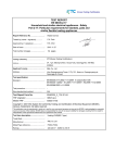
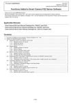
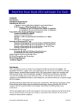
1
ASP ADVANCED SAFETY PRODUCT AS P T E C H N O L O G Y C O R P No.439, Jhen Cian St., Shulin City, Taipei Hsien, Taiwan 238, R.O.C. T E L : 8 8 6 - 2 - 8 6 8 4 1 1 3 6 , F A X: 8 8 6 - 2 - 8 6 8 4 1 1 4 2 , E - m a i l : a s p l a b @ s o - n e t . n e t . t w, a s p . t w n @ g m a i l . c o m A S P dvanced afety roducts T ech n o lo g y C orp Q u a lity‧ R elia b ility‧ P rofessio n a lism ASP ADVANCED SAFETY PRODUCT AS P T E C H N O L O G Y C O R P No.439, Jhen Cian St., Shulin City, Taipei Hsien, Taiwan 238, R.O.C. T E L : 8 8 6 - 2 - 8 6 8 4 1 1 3 6 , F A X: 8 8 6 - 2 - 8 6 8 4 1 1 4 2 , E - m a i l : a s p l a b @ s o - n e t . n e t . t w, a s p . t w n @ g m a i l . c o m Table of Contents Letter to Client Project Notice A. Certificate or Declaration of Conformity (If any) B. Test Report C. Construction Photos(If any) D. Original Design Drawings & Specifications Including Schematics, Block Diagrams, and User or Service Manual E. All Modifications That May Affect Compliance with the EMI or LVD Requirements & Necessary Test Data ASP ADVANCED SAFETY PRODUCT AS P T E C H N O L O G Y C O R P No.439, Jhen Cian St., Shulin City, Taipei Hsien, Taiwan 238, R.O.C. T E L : 8 8 6 - 2 - 8 6 8 4 1 1 3 6 , F A X: 8 8 6 - 2 - 8 6 8 4 1 1 4 2 , E - m a i l : a s p l a b @ s o - n e t . n e t . t w, a s p . t w n @ g m a i l . c o m 致 產 品 行 銷 歐 洲 之 客 戶 (CE Marking) A. 自 1996 年 1 月 1 日 起 , 銷 歐 產 品 必 須 符 合 歐 盟 EMC 指 令 之 後 才 能 上 市 。 B. 自 1997 年 1 月 1 日 起 , 銷 歐 產 品 必 須 同 時 符 合 EMC 指 令 和 低 電 壓 指 令 (LVD-Safety) 之 後 才 能 上 市 。 C. 自 2006 年 7 月 1 日 起 , 銷 歐 產 品 必 須 符 合 歐 盟 RoHS 指 令 之 後 才 能 上 市 。 技 術 檔 案 在 行 銷 前 必 須 準 備 齊 全,以 備 歐 聯 國 家 機 構 隨 時 抽 查,其 內 容 至 少 包 含: 2. 3. Declaration of Conformity (DoC) Form - 必 須 由 歐 洲 分 公 司 或 進 口 商 簽 名 負 責 (見 附 件 樣 本 )。 EMC 測 試 報 告 和 SAFETY 測 試 報 告 - 可 由 實 驗 室 核 發 或 透 過 認 證 機 構 。 原 始 之 設 計 圖 稿 及 規 格 書( 如:線 路 圖、方 塊 圖、PCB Layout 圖、User ’s Manual 4. 5. 和 Sevice Manual 等 ) 敘 述 製 造 時 之 生 產 檢 查 程 序 , 以 確 保 EMC 和 SAFETY 特 性 之 維 持 。 任 何 會 影 響 到 EMC 和 SAFETY 的 變 更 敘 述 和 必 要 之 測 試 記 錄 。 1. 附 註 : * 產 品 上 要 貼 上 歐 聯 指 令 要 求 之 Label 標 示 。 * DoC 簽 名 負 責 之 廠 商,有 責 任 確 保 銷 售 之 產 品 在 EMC 方 面 仍 符 合 規 定。 * 以 上 文 件 必 需 一 份 置 於 DoC 簽 名 負 責 人 手 中 備 查 。 ASP ADVANCED SAFETY PRODUCT AS P T E C H N O L O G Y C O R P No.439, Jhen Cian St., Shulin City, Taipei Hsien, Taiwan 238, R.O.C. T E L : 8 8 6 - 2 - 8 6 8 4 1 1 3 6 , F A X: 8 8 6 - 2 - 8 6 8 4 1 1 4 2 , E - m a i l : a s p l a b @ s o - n e t . n e t . t w, a s p . t w n @ g m a i l . c o m A. C ERTIFIC ATE OR D ECL AR ATION OF C ONFORMI TY (I F A NY ) ADVANCED SAFETY PRODUCT ASP TECHNOLOGY CORP No.439, Jhen Cian St., Shulin City, Taipei Hsien, Taiwan 238, R.O.C. TEL:886-2-86841136, FAX:886-2-86841142, E-mail: [email protected], [email protected] VERIFICATION OF CONFORMITY We Hereby Certify that ASP R e fere nce : 9 0902 10 T he fo l low in g m en t ione d Prod ucts h a ve b een t es t i n t yp ic a l c o n fig ura t io n b y A S P. P r o duc t Typ e : FOOT SWITCH Model Name : SFM-1, SFM-P1 A p pl ica n t : E-TEN E LECTRONIC C O ., LTD . 5F, N O . 10, L ANE 130, M IN -C HUAN R D ., X INDIAN C ITY, TAIPEI , TAIWAN 23141 Is in compliance to the European Council Directive 2006/95/EC. T h is is to c e r t i f y o n the bas is o f th e tes ts und ertak e n . Th e s ub m i t te d s a mp les o f t he a bo ve i te m i s c ons id er ed to c o mp l y w i th : EN 61058-1: 2002 + A2: 2008 B as ed o n th e desc r i p ti on o f the LVD ( 2 006 / 95 / EC) di r ec t i v e , m an ufac t urer or h is a u tho riz ed r epres en tative w i th in EC sh all a ffix the C E mark ing to th e pr oduc ts if he e nsur e the p rod ucts co mp lies w i th the re le va n t stand ards and draw s u p a dec la ra tion o f c on for m it y. S i gn ed for a nd o n be ha l f o f A S P Tec hno lo g y C o r p . Ke vin Ku / Man ager. ASP Technology Corp. Sep 28 , 2 009 D a te . The tec hnical r epor t issued by ASP will suppor t yo u affix the C E mark ing. EC DECLARATION OF CONFORMITY - LOW VOLTAGE DIRECTIVE We herewith declares that the following designated product Foot Switch SFM-1, SFM-P1 (Product identification) Complies with the requirement of the European Community Directive 2006/95/EC. This declaration applies to all specimens manufactured in accordance with the attached manufacturing drawings that form parts of this declaration. Assessment of compliance of the product with the requirements relating to the Low Voltage Directive (LVD) was based on the following standards: EN 61058-1: 2002 + A2: 2008 (Identification of regulations / standards) This declaration is the responsibility of the manufacturer / importer E-TEN ELECTRONIC., LTD. 5F, NO. 10, LANE 130, MIN-CHUAN RD., XINDIAN CITY, TAIPEI, TAIWAN 23141 (Name / Address) MANUFACTURER / IMPORTER (Date) (Surname, forename ) (Company Stamp) ASP ADVANCED SAFETY PRODUCT AS P T E C H N O L O G Y C O R P No.439, Jhen Cian St., Shulin City, Taipei Hsien, Taiwan 238, R.O.C. T E L : 8 8 6 - 2 - 8 6 8 4 1 1 3 6 , F A X: 8 8 6 - 2 - 8 6 8 4 1 1 4 2 , E - m a i l : a s p l a b @ s o - n e t . n e t . t w, a s p . t w n @ g m a i l . c o m T EST B. R EPORT ASP CE R EPORT ASP T E C H N O L O G Y C O R P I S S U E D AT E 2009 SEP 28 IEC/EN 61058-1 Safety of household and similar electrical appliances Report Reference No. .....................: 9090210 Date of issue.....................................: 2009.09.28 Total number of pages......................: 26 Applicant’s name ............................: E-TEN Electronic Co., Ltd. Address.............................................: 5F, No. 10, Lane 130, Min-Chuan Rd., Xindian City, Taipei, Taiwan 23141 Test specification: Standard ...........................................: EN 61058-1:2002 + A2:2008 Test procedure..................................: LVD report Non-standard test method…………..: N/A Test item description .................... : Foot Switch Trade Mark .......................................: Not Provided. Manufacturer.....................................: E-TEN Electronic Co., Ltd. 5F, No. 10, Lane 130, Min-Chuan Rd., Xindian City, Taipei, Taiwan 23141 Model/Type reference.......................: SFM-1, SFM-P1 Ratings..............................................: AC 250V, 10A Tested by (name + signature)......: Jason Lin Approved by (+ signature) ...........: Kevin Ku Report: 9090210 1 Rev 1.5 ASP CE R EPORT ASP T E C H N O L O G Y C O R P I S S U E D AT E 2009 SEP 28 Summary of testing: Tests performed (name of test and test clause): Testing location: ASP TECHNOLOGY CORPORATION. No.439, Jhen Cian St., Shulin City, Taipei Hsien, Taiwan 238, R.O.C. Summary of compliance with National Differences: N/A Copy of marking plate: E-TEN Electronic Co., Ltd. Product Type: Foot Switch Model: SFM-1 Input: AC 250V, 10A Report: 9090210 E-TEN Electronic Co., Ltd. Product Type: Foot Switch Model: SFM-P1 Input: AC 250V, 10A 2 Rev 1.5 ASP CE R EPORT ASP T E C H N O L O G Y C O R P I S S U E D AT E 2009 SEP 28 Test item particulars .................................................. : Classification of installation and use ............................ :Class I appliance. Supply Connection........................................................ :-...................................................................................... :-...................................................................................... :-Possible test case verdicts: - test case does not apply to the test object..................:N/A - test object does meet the requirement .......................:P (Pass) - test object does not meet the requirement .................:F (Fail) Testing ..........................................................................: Date of receipt of test item ............................................:Sep 10, 2009 Date (s) of performance of tests ...................................:Sep 14, 2009 ~ Sep 25, 2009 General remarks: "(see remark #)" refers to a remark appended to the report. "(see appended table)" refers to a table appended to the report. Throughout this report a comma is used as the decimal separator. The test results presented in this report relate only to the object tested. This report shall not be reproduced except in full without the written approval of the testing laboratory. General product information: Model SFM-P1 is identical to model SFM-1 except SFM-P1 without metal protective cover. Detail information see part C construction photos and part D. Report: 9090210 3 Rev 1.5 ASP CE R EPORT ASP T E C H N O L O G Y C O R P Clause Requirement - Test 8 MARKING AND DOCUMENTATION P 8.1 Information provided by marking (Ma) or by documentation (Do) P Switch with Common Type Reference (C.T.) or C.T. / U.T. switch with Unique Type Reference (U.T.) ........ : P Switch identification: P - Ma: manufacturer's name or trademark .......... : Not provided. P - Ma: type reference ........................................... : SFM-1 P Switch environment/mounting: P - Do: degree of protection................................... : IP 20 P - Do: degree of protection against electric shock: P - Do: method of mounting................................... : By electrician. P Temperature: P - Ma (C.T.), Do (U.T.): ambient temperature 25 degree C limits.................................................................... : P Electrical load: P - Ma (C.T.), Do (U.T.): rated voltage or rated 250Vac voltage range (V) ................................................ : P - Ma (C.T.), Do (U.T.): nature of supply ............. : P - Ma (C.T.), Do (U.T.): rated frequency (Hz)...... : N/A 8.1.1 8.1.2 8.1.3 8.1.4 8.1.5 Report: 9090210 Result - Remark I S S U E D AT E 2009 SEP 28 Verdict - Ma (C.T.), Do (U.T.): rated current: Ir; Im; Ic; Il 10A (A) ....................................................................... : P - Do (U.T.): relevant details for declared specific loads ................................................................... : P - Ma/Do (C.T.), Do (U.T.): for switches for more than one circuit, the current (A) applicable to each circuit and to each terminal ....................... : P Terminals/conductors: P - Ma: all terminals identified................................ : P - Ma: terminals for earthing conductors, earth symbol ................................................................ : N/A - Do: information for terminal for prepared conductors or the use of a special tool .............. : N/A - Do: method of connection and disconnection for screwless terminals....................................... : P - Do: type of conductor to be connected to the terminal ............................................................... : P - Do: suitability for interconnection of two or more conductors................................................. : N/A 4 Rev 1.5 ASP Clause 8.1.6 8.1.7 8.1.8 CE R EPORT ASP T E C H N O L O G Y C O R P Requirement - Test Result - Remark I S S U E D AT E 2009 SEP 28 Verdict - Do: type of solder terminal ............................... : N/A - Do: suitability for connection of unprepared supply conductors............................................... : N/A - Do: suitability for connection of prepared supply conductors............................................... : N/A - Do: cord switch non-rewirable documented .... : N/A - Do: cord switch suitability only for flat cords .... : N/A Operating cycles/sequence: N/A - Ma (C.T.), Do (U.T.): number of operating cycles .................................................................. : N/A - Do: operating sequence for switch with more than one circuit ................................................... : N/A Signal indicator: N/A - Ma: max. power of tungsten filament lamps (W) ...................................................................... : N/A - Do: function of the illuminated indicator........... : N/A Circuit disconnection: P - Ma (C.T.), Do (U.T.): micro-disconnection ...... : P Insulating material: P - Do: proof tracking index, PTI ........................... : P Switch category: P - Do: category of appliance ................................ : P - Do: category or type of luminaire according to IEC 60598-1 ....................................................... : P 8.4 Information about rated current and rated 250Vac, 10A voltage ................................................................ : P 8.5 Information about rated ambient temperature ... : N/A 8.6 Symbol for Class II not used .............................. : P 8.7 Information about rated operating cycles........... : N/A 8.8 Required marking shall preferably be on the body of the switch P Not on screws, removable washers or other parts removable during installation of the switch P Marking shall be legible and durable: P - water P - hexane P Enclosed switches, direction of actuation shall be clearly indicated, "O" ..................................... : P 8.1.9 8.1.10 8.9 8.10 Report: 9090210 5 Rev 1.5 ASP CE R EPORT ASP T E C H N O L O G Y C O R P Clause Requirement - Test 8.10.1 Cord switches for luminaires, no OFF marking P 9 PROTECTION AGAINST ELECTRIC SHOCK P 9.1 Live parts not accessible when switches fixed and connected (except lamps with caps) P Switches for Class II, metal parts not accessible if separated from live parts by basic insulation only P Compliance is checked by inspection and with the standard test finger (IEC 60529) P Lacquer, enamel, paper, cotton or similar not used for protection against contact with live parts (if soften in heat) P 9.2 Actuating member shall be fixed adequately (if soften in heat) P 9.3 Accessible parts of actuating members shall be of insulating material or accessible metal parts separated from live parts by double or reinforced insulation P Capacitors shall not be connected to unearthed metal parts P Metal casing of capacitors shall be separated by supplementary insulation from accessible unearthed metal parts P 9.10.1 Non-rewirable cord switches tested as delivered P 10 PROVISION FOR EARTHING P 10.1 Switches for Class II appliances shall have no provision for earthing the switch N/A Terminals for earthing continuity only if separated from live parts by basic insulation or supplementary insulation for accessible parts N/A 10.2 Earthing terminals and terminations shall not be connected electrically to neutral terminal N/A 10.4 Connection of earthing terminal or termination shall be of low resistance; current (A): 1,5 times the rated current but not less then 25A; resistance not exceeding 50m ....................... : N/A Earthing terminals shall be of a size at least equal to corresponding current-carrying terminal; terminal size ........................................ : N/A No loosening without a tool N/A 9.4 Result - Remark I S S U E D AT E 2009 SEP 28 Ω 10.5 Report: 9090210 6 Verdict Rev 1.5 ASP Clause CE R EPORT ASP T E C H N O L O G Y C O R P Requirement - Test I S S U E D AT E 2009 SEP 28 Result - Remark Verdict Clamping means locked against accidental loosening N/A 10.6 Thread-cutting and thread-forming screws, at least two screws are used for each connection N/A 10.7 No risk of corrosion between earthing terminal and the copper of the earthing conductor or any other metal N/A 10.8 Body of an earthing terminal: brass or other metal no less resistant to corrosion N/A 10.9 If the body is part of a frame or enclosure of aluminium alloy, precautions to prevent corrosion with copper N/A 11 TERMINALS AND TERMINATIONS P 11.1.1 Terminals for unprepared copper conductors and not requiring the use of a special purpose tool P 11.1.1.1.1 Terminals shall be such that connection is made by screws, nuts, springs or other equally effective means P No special purpose tool for connection or disconnection necessary P Terminals shall be fixed so that they do not work loose when the clamping means are tightened or loosened P Floating terminals are permitted if they do not impair the correct operation P Compliance: 10 times fastening and loosening; max. cross-sectional area (mm²); torque (Nm) . : P 11.1.1.1.2 11.1.1.1.3 11.1.1.1.4 Report: 9090210 Conductors cannot slip out from terminals while being connected or while the switch is being operated as intended: N/A - max. cross-sectional area (mm²)..................... : N/A - min. cross-sectional area (mm²) ...................... : N/A - number of conductors ...................................... : N/A - torque (Nm) ...................................................... : N/A - after the test, conductor shall not have escaped from gap between the clamping means and retaining device N/A Terminals for flexible conductor located so that there is no risk of contact between live parts and accessible metal parts N/A 7 Rev 1.5 ASP Clause CE R EPORT ASP T E C H N O L O G Y C O R P Requirement - Test Result - Remark I S S U E D AT E 2009 SEP 28 Verdict For Class II, between live parts and metal parts separated by supplementary insulation only from accessible metal parts N/A Furthermore, no risk of short-circuiting those terminals electrically connected together by switch action N/A 11.1.1.1.5 Terminals clamp the conductor without undue damage to the conductors P 11.1.1.1.6 Insertion of the conductor is prevented by a stop, if further insertion may reduce creepage distances and/or clearance or influence the mechanism of the switch N/A Screw-type terminals for unprepared copper conductors N/A Screw-type terminal............................................ : N/A Terminals shall allow the connection of conductors: N/A flexible: cross-sectional area (mm²): required; measured............................................................ : N/A Terminals clamp the conductor reliably and between metal surfaces: N/A - size ................................................................... : N/A - min. cross-sectional area (mm²) ...................... : N/A - max. cross-sectional area (mm²)..................... : N/A - torque (Nm) ...................................................... : N/A - pull (N) for 1 min............................................... : N/A - during the test, the conductor shall not move noticeably in the terminal N/A 11.1.1.2.3 Screws and nuts for clamping the conductors shall not serve to fix any other parts P 11.1.1.3 Screwless terminals for unprepared copper conductors N/A 11.1.1.3.1 Screwless terminal shall allow the connection of conductor up to and including 1,5 mm² for flexible conductors; size (mm²) .......................... : N/A It shall be obvious how the insertion and disconnection are intended N/A Disconnection of a conductor shall require an operation, other than a pull at the conductor N/A Disconnection manually with or without the help of a tool N/A Opening for the use of a tool clearly distinguishable from the opening for the conductor N/A 11.1.1.2 11.1.1.2.1 11.1.1.2.2 Report: 9090210 8 Rev 1.5 ASP CE R EPORT ASP T E C H N O L O G Y C O R P I S S U E D AT E 2009 SEP 28 Clause Requirement - Test 11.1.1.3.2 Screwless terminals withstand mechanical stress occurring in normal use N/A Conductor clamped reliably and between metal surfaces (if the current does not exceed 0,2) N/A Flexible: five insertions and disconnections N/A Size ..................................................................... : N/A Number of conductors........................................ : N/A Pull (N) for 1 min................................................. : N/A During the test, the conductor shall not come out of the terminal N/A After the test, terminals and clamping means have not worked loose N/A Screwless terminals for interconnection of more than one conductor: N/A - after insertion, operation of one clamping means is independent of the other N/A - during the disconnection, conductors can be disconnected either simultaneously or separately N/A Screwless terminals withstand thermal stress occurring in normal use (this test is carried out for switch with number of operating cycles < 10 000 or when the clamping means forms part of the conductive path through the switch): N/A - ambient temperature (°C) ................................ : N/A - rated current (A) ............................................... : N/A - after the 192 Test cycles (duration 1), the temperature rise does not exceed 55 ................ : N/A Insulation piercing terminals for insulated unprepared copper conductors N/A Requirements and tests under consideration N/A 11.1.1.3.3 11.1.1.3.4 11.1.1.4 Result - Remark Verdict 11.1.2 Terminals for unprepared copper conductor and/or requiring the use of a special purpose tool (not for rewirable cord switches) P 11.1.2.1.1 Terminals shall allow the connection is made as declared (checked during the tests of clauses 16 and 19) P Terminals shall allow connection of conductors as declared; cross-sectional areas (mm²): required; measured ............................................ : P Connection reliably between metal surfaces, without undue damage to the conductor (checked during the tests of clauses 16 and 19) P 11.1.2.1.2 11.1.2.1.3 Report: 9090210 9 Rev 1.5 ASP CE R EPORT ASP T E C H N O L O G Y C O R P I S S U E D AT E 2009 SEP 28 Clause Requirement - Test 11.1.2.1.4 Insertion of the conductor limited by a stop, if further insertion may reduce creepage distance and/or clearance or influence the mechanism of the switch N/A Screw-type terminals for prepared copper conductors N/A No further specific requirements N/A 11.1.2.3 Screwless terminals for prepared copper conductors N/A 11.1.2.3.1 Terminals clamp the conductor between metal surfaces (except terminals for current ≤ 0,2) N/A 11.1.2.3.2 Screwless terminals withstand thermal stress occurring in normal use (checked by test according to 11.1.1.3.4) N/A 11.1.2.4 Tabs of flat quick-connect terminations N/A 11.1.2.4.1 Tabs forming part of a switch comply with the dimensions according to fig. 7: N/A - nominal size (mm)............................................ : N/A - A (mm): required (max.); measured ................ : N/A - B (mm): required (min.); measured ................. : N/A - C (mm): required (+0,04/-0,03); measured ..... : N/A - D (mm): required (± 0,1); measured................ : N/A - E (mm): required (max.); measured ................ : N/A - F (mm): required (max.); measured ................ : N/A - G (mm): required (min.); measured................. : N/A - H2 (mm): required (min.); measured............... : N/A - I (mm): required (max. diameter); measured .. : N/A Tabs with different dimensions are permitted to prevent any mating with female of fig. 8 and prescribed in IEC 760 N/A 11.1.2.4.2 Tabs may have an optional detent for latching (area EF, fig. 7) N/A 11.1.2.4.3 Provision for non-reversible connections located in area EF N/A 11.1.2.4.4 Material and plating of tabs shall be appropriate to the max. temperature: N/A - max. temperature of tab (°C) ........................... : N/A - material and plating.......................................... : N/A Tabs allow application withdrawal of female without damage to the switch: N/A - tab size ............................................................. : N/A - push (N)............................................................ : N/A - pull (N) .............................................................. : N/A 11.1.2.2 11.1.2.4.5 Report: 9090210 Result - Remark 10 Verdict Rev 1.5 CE R EPORT ASP Clause ASP T E C H N O L O G Y C O R P Requirement - Test I S S U E D AT E 2009 SEP 28 Result - Remark Verdict - no displacement or damage occurs N/A Tabs allow connection of the appropriate uninsulated female connectors (during the check no strain or distortion occurs to any of the tabs or adjacent parts) N/A Insulation piercing terminals for prepared insulated copper conductors N/A Requirements and tests are under consideration N/A 11.1.2.6 Solder terminals N/A 11.1.2.6.1 Solder terminals shall have sufficient solderability, tests according to IEC 68-2-20, test Ta: N/A - test method 1 (solder bath at 235 °C) N/A - test method 2 (soldering iron at 350 °C) N/A - soldering iron size N/A - final measurement: temperature rise according to Cl. 16 N/A Solder terminals shall have sufficient resistance to soldering heat: N/A - type 1: checked during the tests of 11.1.2.6.1, after the tests the terminals shall not have worked loose or displaced in a manner impairing further use N/A - type 2: tests according to IEC 68-2-20, test Tb: test method 1A (solder bath at 260 °C) test method 2 (soldering iron 350 °C) soldering iron size N/A After the tests the terminals shall not have worked loose or displaced in a manner impairing further use N/A Solder terminals (see 7.2.12) provided with means for mechanically securing the conductor: N/A - hole for hooking-in the conductors; or N/A - edges shaped for wrapping-around; or N/A - clamping means N/A 11.1.3 Additional requirements for terminals for supply connection and the connection of external cords N/A 11.1.3.1 Terminal located near its corresponding terminal of different polarity, and to the earthing terminal N/A According to IEC 335-1 type of attachment ....... : N/A 11.1.2.4.6 11.1.2.5 11.1.2.6.2 11.1.2.6.3 12 CONSTRUCTION P 12.1 Constructional requirements relating to protection against electric shock P Report: 9090210 11 Rev 1.5 ASP CE R EPORT ASP T E C H N O L O G Y C O R P I S S U E D AT E 2009 SEP 28 Clause Requirement - Test 12.1.1 Basic and supplementary insulation tested separately when double insulation is employed P 12.1.2 No reduction of creepage and clearance distances as a result of wear (see Cl. 20) P If any conductive part becomes loose and moves out of position, creepage and clearance distances are not reduced to less than 50% (see Cl. 20) P Integrated conductors rigid, fixed or insulated so that creepage and clearance distances are not reduced (see Cl. 20) P 12.1.101 Solder terminals according to 7.2.13, additional provision must be provided P 12.2 Constructional requirements relating to safety during mounting and normal operation of the switch P 12.2.1 Covers, cover plates, removable actuators and the like displaced or removed only by use of a tool P Fixings for a cover or cover plate do not serve to fix any other parts except actuating member P Not possible to mount removable parts such that indication of switch positions does not correspond with the actual switch position P 12.2.2 Fixing screws of covers or cover plates captive P 12.2.3 When the actuating member is removed switch not damaged (checked by tests of 18.4) P 12.2.4 Pull-cord insulated from live parts P Possibility to fit or to replace without removing parts causing accessibility to live parts P 12.1.3 12.2.5 Result - Remark Illuminated indicator incorporated in a switch No illuminated indicator provides the correct indication as declared; marked voltage (V) ............................................. : Verdict N/A 12.3 Constructional requirements relating to the mounting of switches and to the attachment of cords: P 12.3.1 Method of mounting of switches does not adversely affect compliance with this standard P 12.3.1.1 Switch cannot rotate or be displaced, cannot be removed from an appliance without the aid of a tool P If the removal of a part is necessary during the normal use, requirements of clauses 9, 15 and 20 are satisfied before and after the removal P Report: 9090210 12 Rev 1.5 ASP CE R EPORT ASP T E C H N O L O G Y C O R P Clause Requirement - Test Result - Remark 12.3.10.1 Cord anchorages, conductors relieved from strain and twisting, sheath of the cord protected from abrasion and kept in position I S S U E D AT E 2009 SEP 28 Verdict N/A 12.3.10.2 Clear how relief from strain and twisting is effected P 12.3.10.3 Makeshift method not used P 12.3.10.4 Cord anchorages shall be of insulating material or if of metal, insulated from accessible metal parts and insulating surfaces by supplementary insulation P 12.3.10.5 Cord anchorages of rewirable cord switches do not fall out when the cover is removed P 12.3.10.6 Cord anchorages so designed that: P - cord is not fixed by penetration of its insulation P - cord cannot touch clamping screws of the cord anchorage (if accessible) P - cord is not clamped by a screw (if of metal) P Rewirable switches P - at least one part securely fixed to the switch P - replacement of the cord does not use a special tool P - suitable for different types of cords P Rewirable switches: replacement of cord easy; compliance checked by pull and torque tests P 12.3.10.7 Non-rewirable: Report: 9090210 N/A - type of cord....................................................... : -- - nominal cross-sectional area (mm²) ................ : -- Rewirable: P - round cord: nominal cross-sectional area (mm²) .................................................................. : -- - flat cord: nominal cross-sectional area (mm²) . : -- Clamping screws of cord anchorage: P - insulating type; torque (2/3): torque (Nm) ........ : P - metal type; torque (2/3): torque (Nm) .............. : P Pull test: pull 100 times at 60s P Torque test: torque (Nm) for 1 min .................... : 0,15 m / 0,25 m P During the test, cord not damaged P After the test, displacement ≤ 2 mm .................. : P 13 Rev 1.5 ASP Clause CE R EPORT ASP T E C H N O L O G Y C O R P Requirement - Test Result - Remark I S S U E D AT E 2009 SEP 28 Verdict no strain at the connection P creepage distances and clearances not reduced P no break in the electrical connections (non-rewirable switch) P 12.3.10.8 Non-rewirable switches: cord complying with HD 21 / HD 22 HD 21 or HD 22.................................................. : P 12.3.10.9 Screws do not serve to fix any other component, unless P switch is rendered inoperable or manifestly incomplete P Component cannot be removed without a tool P Cords are capable of withstanding the bending P Inlet or bushing no sharp edges P Cord-guard not integral with the cord, except P switches classified according to 7.2.3 P Flexing test (5000 flexings, weight: 1 g): P - rated current (A) ............................................... : -- - type of cord; cross-sectional area (mm²)......... : -- - type of cord; cross-sectional area (mm²)......... : -- During the test: P - no interruption of the test current P - no short-circuit between conductors P After the test, no damage P Rewirable switches: adequate space for external conductors P Possibility to check correct connection P Rewirable single-pole switch: additional terminal(s) for non-switched conductor(s) P Terminals allow the connection of both incoming and outgoing ends P 12.3.10.13 Non-rewirable switches shall have soldered, welded or crimped terminations ......................... : P 12.3.10.14 Prewired switch: current rating of the cord compatible with the current of table 102; rated current (A); nominal cross-sectional area (mm²): required; measured ............................................ : P Rewirable switches provided for earthing continuity: ample space for slack protective earth conductor P 12.3.10.10 12.3.10.11 12.3.11.12 12.3.10.15 Report: 9090210 14 Rev 1.5 ASP Clause 12.3.10.16 12.3.10.17 CE R EPORT ASP T E C H N O L O G Y C O R P Requirement - Test Result - Remark I S S U E D AT E 2009 SEP 28 Verdict Test: protective earth conductor led to its terminals and cut off 8 m longer than necessary; possibility to house the loop freely without squeezing or pressing the core P Switches with means for suspension shall have adequate mechanical strength N/A Test (barrier): cylindrical steel rod pushed with a force of 75N for 10s; the rod shall not pierce the barrier N/A Pull test: pull 60s for 10N to supply flexible cord; during the test, means for suspension shall not break, or N/A if broken live parts shall not become accessible to test finger N/A Pull test with a round head screw: pull 50s for 10N ; during the test, means for suspension shall not break, or N/A if broken live parts shall not become accessible to test finger N/A 13 MECHANISM P 13.1 For d.c. switches, speed of contacts independent of the speed of actuating except switches ≤ 28V or ≤ 0,1A N/A Moving contacts rest only in ON and OFF position (intermediate position permitted) N/A ON position if contact pressure is sufficient (checked by tests of Cl. 16) N/A OFF position if separation of the contact is adequate, checked by tests of clauses 15 and 20 N/A Intermediate position checked by test of Cl. 15 for OFF position N/A 13.3 Rest position, automatic return to one of them after release (except only one rest position) N/A 13.4 Cord operated switch after actuating, parts of mechanism are in position to allow the next cycle of actuation; pull 45° vertically downwards, or N/A 70N at 45° to the vertical N/A 13.2 13.5 Report: 9090210 Multi-pole switch, all poles make and break simultaneously 15 P Rev 1.5 ASP Clause CE R EPORT ASP T E C H N O L O G Y C O R P Requirement - Test I S S U E D AT E 2009 SEP 28 Result - Remark Verdict Neutral makes before and breaks after the other poles P 14 PROTECTION AGAINST INGRESS OF SOLID OBJECTS, DUST AND WATER AND PROTECTION AGAINST HUMID CONDITIONS P 14.1 Protection against ingress of solid objects: degree of protection ........................................... : P 14.2 Protection against ingress of dust: IP number, IP2X first numeral; no deposit of dust inside (IP6x).... : P 14.3 Protection against harmful ingress of water: IP IPX0 number, second numeral ................................... : P - temperature (°C): 70°C, (T + 30) °C or............ : N/A - glands: torque (Nm) ......................................... : N/A - fixing screws for enclosures: torque (Nm) ....... : N/A - after test switch withstands electric test specified in 15.3 P No trace of water or reduction of creepage and clearance distances (see Cl. 20) P Protection against humid conditions: P - duration: 48hrs for IPx0, 168hrs for other 48hrs switches .............................................................. : P - switch does not show any damage P 15 INSULATION RESISTANCE AND DIELECTRIC STRENGTH P 15.2 Insulation resistance (500Vdc for 1 min): P - operational insulation: ≥ 2 Ω ............................ : P - basic insulation: ≥ 2 Ω...................................... : P - supplementary insulation: ≥ 5 Ω ...................... : P - reinforced insulation: ≥ 7 Ω .............................. : P Dielectric strength: P - rated voltage (V)............................................... : 250Vac P - functional insulation, test voltage (V) ............... : 1500Vac P - basic insulation, test voltage (V) ...................... : 1500Vac P - supplementary insulation, test voltage (V)....... : 1500Vac P - reinforced insulation, test voltage (V)............... : 3000Vac P - across full disconnection, test voltage (V) ....... : 1500Vac P - across micro-disconnection, test voltage (V)... : 500Vac P 14.4 15.3 Report: 9090210 16 Rev 1.5 ASP Clause CE R EPORT ASP T E C H N O L O G Y C O R P Requirement - Test I S S U E D AT E 2009 SEP 28 Result - Remark Verdict No flashover or breakdown shall occur P 16 HEATING P 16.2 Contacts and terminals: P - ambient temperature of actuating member .... : <55°C P - ambient temperature of other parts: P 16.3 Report: 9090210 <55°C - rated current (A) ............................................... : 10A P - rated voltage (V)............................................... : 250Vac P - test current, 1,06 times max. rated current (A) : 10.6A P - test voltage (V) ................................................. : 250Vac P - cross-sectional area (mm²) .............................. : -- - terminals, torque (Nm) ..................................... : -- Temperature rise at the terminals not exceeding 1) 45° (supplementary test: samples 4, 5, 6) ......... : 2) 3) 4) 5) 6) P Other parts of switches do not attain excessive temperatures during the normal use: P - test current (A): 1.06 times max. rated current : 10.6A P - ambient temperature ....................................... : 22°C P Other heating sources: max. declared power 2644W (W) ...................................................................... : P Test voltage (V) .................................................. : 250Vac P Temperature rise of rubber or polyvinyl chloride insulation of non-detachable cables and cords: P - without T-marking ≤ 75 °C ............................... : P - with T-marking ≤ T °C ...................................... : N/A Temperature rise of cord sheaths used as supplementary insulation ≤ 60 °C ...................... : P Temperature rise of rubber, other than synthetic, used for gasket or other parts: P - when used as supplementary insulation or as reinforced insulation ≤ 65 °C .............................. : P - in other cases ≤ 75 °C...................................... : P Temperature rise of material used as insulation other than that specified for wires: P - thermosetting materials.................................... : P - thermoplastic materials .................................... : P 17 Rev 1.5 ASP Clause 17 17.2.4 17.2.5 Report: 9090210 CE R EPORT ASP T E C H N O L O G Y C O R P Requirement - Test I S S U E D AT E 2009 SEP 28 Result - Remark Verdict Temperature rise of outer surface of capacitors: P - with marking of maximum operating temperature (T) ≤ (T - 10) °C ............................. : P - without marking of maximum operating temperature, small ceramic capacitors for radio and television interference suppression ≤ 75 °C: P - without marking of maximum operating temperature, other capacitors ≤ 45 °C............... : P Temperature rise of all accessible surfaces except those of actuating members or handles ≤ 85 °C................................................................ : P Temperature rise of accessible surfaces of actuating members or handles which are held for short periods only: P - of metal ≤ 60 °C ............................................... : P - of porcelain or vitreous material ≤ 70 °C ......... : P - of moulded material or rubber ≤ 85 °C ............ : P ENDURANCE P Rated voltage (V)................................................ : 250Vac P Rated current (A) ................................................ : 10A P Ambient temperature ......................................... : 30°C P Operations per min............................................. : 30 per min P Type of circuit ..................................................... : P Increased voltage test at accelerated speed: P - test voltage (V): 1,15 n ..................................... : 287.5Vac P - test current, making (A).................................... : P - test current, breaking (A) ................................. : P - number of cycles: 100; time constant (ms)...... : P - samples 1, 2, 3................................................. : 1) 2) 3) P - supplementary test: samples 4, 5, 6................ : 4) 5) 6) P Test at low speed: P - test voltage (V) ................................................. : 287.5Vac P - test current, making (A).................................... : P - test current, breaking (A) ................................. : P 18 Rev 1.5 ASP Clause 17.2.6 17.2.7 17.3 Report: 9090210 CE R EPORT ASP T E C H N O L O G Y C O R P Requirement - Test Result - Remark I S S U E D AT E 2009 SEP 28 Verdict - number of cycles: 100; time constant (ms)...... : P - samples 1, 2, 3................................................. : 1) 2) 3) P - supplementary test: samples 4, 5, 6................ : 4) 5) 6) P Test at high speed (only for switches with more than one pole): P - test voltage (V) ................................................. : 287.5Vac P - test current, making (A).................................... : P - test current, breaking (A) ................................. : P - number of cycles: 100; time constant (ms)...... : P - samples 1, 2, 3................................................. : 1) 2) 3) P - supplementary test: samples 4, 5, 6................ : 4) 5) 6) P Test at accelerated speed: P - test voltage (V) ................................................. : 287.5Vac P - test current, making (A).................................... : P - test current, breaking (A) ................................. : P - number of cycles; time constant (ms).............. : P - samples 1, 2, 3................................................. : 1) 2) 3) P - supplementary test: samples 4, 5, 6................ : 4) 5) 6) P After all tests, switch is deemed to comply if: P - all actions function as declared P - temperature rise at the terminals does not 1) exceed 55 degree C (supplementary test: 2) samples 4, 5, 6) .................................................. : 3) 4) 5) 6) P - reduced (75%) dielectric strength requirement is met, test voltage (V) ....................................... : P 19 Rev 1.5 ASP Clause CE R EPORT I S S U E D AT E 2009 SEP 28 ASP T E C H N O L O G Y C O R P Requirement - Test Result - Remark Verdict - no fault between live parts and earth metal, accessible metal part, or actuating member has occurred P 18 MECHANICAL STRENGTH P 18.1 Switches have adequate mechanical strength P 18.1.1 Accessible parts of actuating members have adequate mechanical strength or adequate protection if the actuating member is broken. Checked by tests of 18.2, 18.3, 18.4 as appropriate P Impact test, three blows of: P 18.2 18.3 18.4 18.10.1 Report: 9090210 - 0,5 m for all accessible surfaces No damage. P - 1,0 m for foot-actuated switches No damage. P Foot-operated switches, in addition, subjected to No damage. a force of 750N for 1 min P After the tests, switches comply with the requirements of clauses 9, 13, 15 and 20 P Insulating lining, barriers have not worked loose P Possibility to remove and to replace detachable and other external parts P Cord-operated switches: no damage after pull test; pull (N), normal direction for 1 min; pull (N), 45° from normal direction for 1 min.................... : N/A Actuating member: N/A - pull test to try to pull off: pull (N) for 1 min ....... : 15 / 30 N/A - push test: 30N for 1 min for all actuating members N/A After the tests specimen shows no damage N/A Pull and push of 30N applied to the actuating means if without actuating member N/A Tumbling barrel (other than foot operated switches): N/A - rewirable: cord type; cross-sectional area (mm²) .................................................................. : N/A - non-rewirable as delivered N/A - number of falls.................................................. : 1000 / 500 / 100 N/A - during the test: connection shall not become loose N/A - after the test, no damage N/A 20 Rev 1.5 ASP CE R EPORT ASP T E C H N O L O G Y C O R P Clause Requirement - Test Result - Remark 18.10.2 Compression test (only for foot operated switches): 3 compressions in three different positions; force of 250N increased to 750N and maintained for 1 min; after the test, no damage No damage. I S S U E D AT E 2009 SEP 28 Verdict P 19 SCREWS, CURRENT-CARRYING PARTS AND CONNECTIONS P 19.1 General requirements for electrical connections: contact pressure is not transmitted through insulating material other than ceramic or like, unless there is sufficient resiliency (not applicable for connections with current ≤ 20 A) P 19.2 Screwed connections P 19.2.1 Screwed connections, electrical or other withstand mechanical stresses P 19.2.2 Screws transmitting contact pressure in engagement with a metal thread P Screws not of soft metal or metal liable to creep, such as zinc or aluminium P 19.2.3 Screws operated during the mounting of switches not of the thread-cutting type P 19.2.4 Thread-forming screws not used for connection of current-carrying parts (unless they use a suitable means of locking) P Thread-cutting screws not used for electrical connection of current-carrying parts (unless they generate ISO hread or equivalent) P Provisionally SI, BA and UN are equivalent to ISO hread P Screws or nuts tightened and loosened: P - 10 times for screws in engagement with a thread of insulating material - 5 times for all other cases P Nuts concentric with the button: tightened and loosened 5 times: P - 0,8 m if insulating material P - 1,8 m if metal P Terminal screws: diameter (mm); torque (Nm) . : 3.9mm, 1.2Nm P Assembly screws: diameter (mm); torque (Nm) : 4.87mm, 2.0Nm P Cord anchorages: diameter (mm); torque (Nm) : Report: 9090210 N/A N/A Other screws: diameter (mm); torque (Nm) ...... : 3.88mm, 1.2Nm P During the test, terminals do not work loose and no damage P 21 Rev 1.5 ASP CE R EPORT ASP T E C H N O L O G Y C O R P I S S U E D AT E 2009 SEP 28 Clause Requirement - Test 19.2.5 Screwed glands: ................................................. : metal / insulating N/A Diameter metal rod (mm); torque (Nm) ............. : N/A After the test, the glands and the enclosure show no damage N/A 19.2.6 Correct introduction of the screws into the screw holes ensured N/A 19.2.7 Screws and rivets locked against loosening N/A 19.2.8 Screws and nuts for clamping the conductors have ISO hread or equivalent N/A Provisionally SI, BA, UN are comparable to ISO N/A Checked by tests of 19.2 N/A 19.3 Result - Remark Verdict Current-carrying parts, material of current-carrying parts and earthing parts shall be: P - copper, or P - 58% copper for parts worked cold, or P - 50% for other parts P - stainless steel, or P - steel with coating of zinc (ISO 2081) P - steel with coating of nickel and chromium (ISO 1456) P - steel with coating of tin (ISO 2093) P Parts subjected to arcs not of steel with an electroplated coating P Insulating material screws: diameter (mm); torque (Nm) ........................................................ : -- Insulating material screws: diameter (mm); torque (Nm) ........................................................ : -- 19.10.2 Not possible to replace screws of insulating material with metal screws (if impair safety) P 20 CLEARANCES, CREEPAGE DISTANCES AND DISTANCES THROUGH INSULATION P 19.10.1 Report: 9090210 Clearances and creepage distances N/A Distance through insulation: N/A - basic insulation, ≥ 1,0 mm ............................... : P - reinforced insulation, ≥ 2.0 mm........................ : N/A - supplementary insulation, ≥ 1,0 mm ................ : P 22 Rev 1.5 ASP CE R EPORT I S S U E D AT E 2009 SEP 28 ASP T E C H N O L O G Y C O R P Clause Requirement - Test 21 RESISTANCE TO HEAT, FIRE AND TRACKING P 21.1.1 Resistance to heat and fire for accessible parts: P - ball-pressure test: test temperature; diameter of impression ≤ 2 mm......................................... : N/A - glow-wire test at 650 °C : no visible flame or N/A - flame extinguishes within 30s .......................... : N/A 21.1.2 21.1.3 21.1.4 21.2 22 Result - Remark Resistance to heat and fire for parts in contact with or support current-carrying parts: Verdict P - ball-pressure test: test temperature; diameter of impression ≤ 2 mm......................................... : N/A - glow-wire test at 650 °C: no visible flame or N/A - flame extinguishes within 30s .......................... : N/A Resistance to heat and fire for parts in contact with, maintain, or retain in position electrical connections: P - ball-pressure test: test temperature; diameter of impression ≤ 2 mm......................................... : N/A - glow-wire test: test temperature; no visible flame or............................................................... : N/A - flame extinguishes within 30s .......................... : N/A Resistance to heat and fire for all other parts: P - glow-wire test at 550 °C: no visible flame or N/A - flames extinguish within 30s ............................ : N/A Resistance to tracking: P - 50 drops; test voltage (V); PTI (V) ................... : 175 / 250V P - no flashover or breakdown (test not carried out for switches ≤ 50 or for use in clean situations) P RESISTANCE TO RUSTING P Ferrous parts adequately protected against rusting; no signs of rust after exposure to ammonium chloride and moisture treatment in saturated air P 23 ABNORMAL OPERATION AND FAULT CONDITIONS FOR ELECTRONIC SWITCHES N/A 24 COMPONENTS FOR ELECTRONIC SWITCHES N/A 24.1 Protective devices N/A Report: 9090210 23 Rev 1.5 ASP CE R EPORT I S S U E D AT E 2009 SEP 28 ASP T E C H N O L O G Y C O R P Clause Requirement - Test 24.1.1 Fuses N/A 24.1.2 Cut-outs N/A 24.1.2.1 Non-resettable cut-outs N/A 24.1.2.2 Resettable, non-self-resetting cut-outs N/A 24.1.2.3 Self-resetting cut-outs N/A 24.1.3 Protective devices which only decrease the current (for example PTC resistors) N/A 24.1.4 Fusing resistors N/A 24.2 Capacitors N/A 24.3 Resistor N/A 25 EMC REQUIREMENTS P 25.1 Immunity P 25.1.1 Voltage dips and short interruptions P 25.1.2 Withstand to 1, 2/ 50 wave impulses P 25.1.3 Electrical fast transient test P 25.1.4 Electrostatic discharge test P 25.1.5 Radiated electromagnetic field test P 25.1.6 Power-frequency magnetic field test P 25.2 Emission P 25.2.1 Low-frequency emission P 25.2.2 Radio-frequency P 1.5.1 TABLE: List of critical components object/part No. Relay Report: 9090210 manufacturer/ trademark OMROM CORP Result - Remark Verdict P type/model Z-15GS-B 24 technical data 15A, 125/250/480 Vac standard ANSI/UL 508 mark(s) of 1 conformity ) UL Rev 1.5 ASP ADVANCED SAFETY PRODUCT AS P T E C H N O L O G Y C O R P No.439, Jhen Cian St., Shulin City, Taipei Hsien, Taiwan 238, R.O.C. T E L : 8 8 6 - 2 - 8 6 8 4 1 1 3 6 , F A X: 8 8 6 - 2 - 8 6 8 4 1 1 4 2 , E - m a i l : a s p l a b @ s o - n e t . n e t . t w, a s p . t w n @ g m a i l . c o m C. C ONSTRUCTION P HO TOS (I F A NY ) ASP CE R EPORT ASP TECHNOLOGY CORP I S S U E D AT E 2009 S E P 28 Annex. EUT Photographs Mode l: SFM-1 Report: 9090210 1 Rev 1.5 ASP CE R EPORT ASP TECHNOLOGY CORP I S S U E D AT E 2009 S E P 28 Annex. EUT Photographs Mode l: SFM-1 Report: 9090210 2 Rev 1.5 ASP CE R EPORT ASP TECHNOLOGY CORP I S S U E D AT E 2009 S E P 28 Annex. EUT Photographs Mode l: SFM-P1 Report: 9090210 3 Rev 1.5 ASP CE R EPORT ASP TECHNOLOGY CORP I S S U E D AT E 2009 S E P 28 Annex. EUT Photographs Mode l: SFM-P1 Report: 9090210 4 Rev 1.5 ASP ADVANCED SAFETY PRODUCT AS P T E C H N O L O G Y C O R P No.439, Jhen Cian St., Shulin City, Taipei Hsien, Taiwan 238, R.O.C. T E L : 8 8 6 - 2 - 8 6 8 4 1 1 3 6 , F A X: 8 8 6 - 2 - 8 6 8 4 1 1 4 2 , E - m a i l : a s p l a b @ s o - n e t . n e t . t w, a s p . t w n @ g m a i l . c o m D. O RIGIN AL D ESIGN D R AWI NGS & S PECIFIC ATIONS I NCLUDING S CHEM ATI CS , B LOCK D I AG R AMS , AND U SER OR S ERVI CE M ANU AL ASP ADVANCED SAFETY PRODUCT AS P T E C H N O L O G Y C O R P No.439, Jhen Cian St., Shulin City, Taipei Hsien, Taiwan 238, R.O.C. T E L : 8 8 6 - 2 - 8 6 8 4 1 1 3 6 , F A X: 8 8 6 - 2 - 8 6 8 4 1 1 4 2 , E - m a i l : a s p l a b @ s o - n e t . n e t . t w, a s p . t w n @ g m a i l . c o m E. A LL M ODIFIC ATIONS T H AT M AY A FFECT C OMPLI ANCE WITH THE EMI LVD R EQUIREMENTS & N ECESS ARY T EST D ATA OR