1
www.nemko.com
TEST REPORT
IEC/EN 60335-2-15
Safety of household and similar electrical appliances
Part 2: Particular requirements for appliances for heating liquids
Report Reference No. ....................:
130229
Date of issue ....................................:
2009-12-10
Tested by (name + signature) ..........:
Andrew Zhai
Approved by (+ signature)................:
William Cheung
Total number of pages .....................:
110 pages
Testing Laboratory Name ..............:
Nemko Hong Kong Ltd.
Address ..........................................:
Unit 1-5, 15/F, CCT Telecom Building, No. 11 Wo Shing Street,
Fotan, Shatin, N.T., Hong Kong
Applicant’s name............................:
China Hangyu Group Co., Ltd.
Address ............................................:
No.16 Beihu Road, Economic Development Zone, Yongkang,
Zhejiang, China
Phone: (+852) 2675 0288
Test specification:
Standard...........................................:
EN 60335-2-15:2002+A1:2005 + A2:2008 with
EN 60335-2-14:2006 +A1:2008 with
EN 60335-1:2002+A1:2004+A11:2004+A2:2006+A12:2006
+A13:2008
EN 50366:2003+A1:2006
Test procedure .................................:
GS
Non-standard test method…………..:
N/A
Test Report Form No. ....................:
IEC60335_2_15E
Test Report Form(s) Originator....................... :
IMQ S.p.A.
Master TRF..................................................... :
Dated 2008-01
Copyright © 2008 IEC System for Conformity Testing and Certification of Electrical Equipment
(IECEE), Geneva, Switzerland. All rights reserved.
This publication may be reproduced in whole or in part for non-commercial purposes as long as the IECEE is acknowledged as
copyright owner and source of the material. IECEE takes no responsibility for and will not assume liability for damages resulting from
the reader's interpretation of the reproduced material due to its placement and context.
If this Test Report Form is used by non-IECEE members, the IECEE/IEC logo and the reference to the CB Scheme
procedure shall be removed.
This report is not valid as a CB Test Report unless signed by an approved CB Testing Laboratory and appended
to a CB Test Certificate issued by an NCB in accordance with IECEE 02.
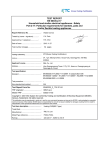
Test item description .....................:
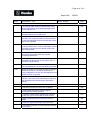
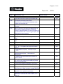
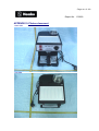
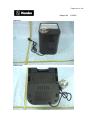
Coffee maker
Trade Mark ....................................... :
Manufacturer .................................... :
China Hangyu Group Co., Ltd.
Model/Type reference ...................... :
HES120A
Ratings ............................................. :
220-240V∼ 50Hz 1400W; Class I
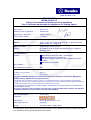
This Test Report, when bearing the Nemko name and logo is only valid when issued by a Nemko laboratory,
or by a laboratory having special agreement with Nemko.
- Page 2 of 110 -
Report No. 130229
Name and address of production-sites (Factories):
China Hangyu Group Co., Ltd.
No.16 Beihu Road, Economic Development Zone, Yongkang, Zhejiang, China
Copy of marking plate:
TRF No. IEC60335_2_15E
- Page 3 of 110 -
Report No. 130229
Summary of testing:
This appliance mainly function is for brewing coffee, and one coffee mill is also incorporated with the
appliance. So EN 60335-2-14 is also considered in the appendix 4.
EMC standards
EN 55014-1:2006
EN 55014-2:1997 + A1:2001+ A2:2008
EN 61000-3-2:2006
EN 61000-3-3:1995 + A1:2001+ A2:2005
EMF standard
EN 50366:2003 + A1:2006
List of attachments:
APPENDIX 1: includes the assessment of all group differences and national deviations to IEC60335-1 and
IEC 60335-2-15;
APPENDIX 2: includes the test result of EMF;
APPENDIX 3: includes the assessment according to EN 60335-2-15:2002 / A2:2008;
APPENDIX 4: includes the assessment according to EN 60335-2-14:2006 +A1:2008;
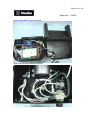
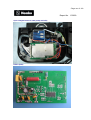
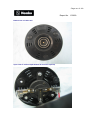
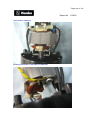
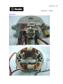
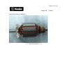
APPENDIX 5: Photos Document
TRF No. IEC60335_2_15E
- Page 4 of 110 -
Report No. 130229
Test item particulars .................................................. : Coffee Maker
Classification of installation and use............................ : Portable appliance
Supply Connection ....................................................... : Supply cord with plug
...................................................................................... :
...................................................................................... :
Possible test case verdicts:
- test case does not apply to the test object .................: N/A
- test object does meet the requirement.......................: P (Pass)
- test object does not meet the requirement.................: F (Fail)
Testing ..........................................................................:
Date of receipt of test item ............................................: 2009-09-01
Date (s) of performance of tests ...................................: 2008-09-02 to 2009-11-03
General remarks:
The test results presented in this report relate only to the object tested.
This report shall not be reproduced, except in full, without the written approval of the Issuing testing laboratory.
"(See Enclosure #)" refers to additional information appended to the report.
"(See appended table)" refers to a table appended to the report.
Throughout this report a comma is used as the decimal separator.
General product information:
Marking label, user manual, packing text:
Instructions and marking shall be in a language acceptable for the country where the equipment is to be
used.
Mains plug:
If the equipment shall be used with a special mains plug which is not listed in the component list (e.g.
United Kingdom), samples of the modified product must be subject to a test according to the relevant
clauses of the product standard.
Other product properties:
Depending on the country where the equipment is to be used, national deviations may be considered.
Samples of the modified product may be tested again according to relevant clauses of the product
standard, modified by national deviations.
TRF No. IEC60335_2_15E
- Page 5 of 110 -
Report No. 130229
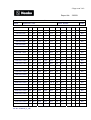
IEC 60335-2-15
Clause
Requirement + Test
5
GENERAL CONDITIONS FOR THE TESTS
Result - Remark
Verdict
P
Tests performed according to cl. 5, e.g. nature of
supply, sequence of testing, etc.
5.2
See Note (IEC 60335-2-15)
N/A
5.3
The test of 19.101 is made after other tests
(IEC 60335-2-15)
N/A
6
CLASSIFICATION
6.1
Protection against electric shock:
Class 0, 0I, I, II, III ....................................................:
6.2
Protection against harmful ingress of water
N/A
Wash boilers and livestock feed boilers shall be at
least IPX3 (IEC 60335-2-15)
N/A
Class I
P
7
MARKING AND INSTRUCTIONS
7.1
Rated voltage or voltage range (V)..........................:
220-240V
P
Nature of supply .......................................................:
∼
P
Rated frequency (Hz) ...............................................:
50Hz
P
Rated power input (W) .............................................:
1400W
P
N/A
Rated current (A) .....................................................:
Manufacturer's or responsible vendor's name,
trademark or identification mark ..............................:
Trademark:
Model or type reference ...........................................:
HES120A
P
N/A
Symbol 5172 of IEC 60417, for Class II appliances
IP number, other than IPX0 .....................................:
P
IPX0
N/A
Symbol IEC 60417-5036, for the enclosure of
electrically-operated water valves in external hosesets for connection of an appliance to the water
mains
N/A
Appliances intended to be partially immersed in
water for cleaning, shall be marked with the
maximum level of immersion, and
(IEC 60335-2-15)
N/A
with the substance of the following: "Do not
immerse beyond this level" (IEC 60335-2-15)
N/A
TRF No. IEC60335_2_15E
- Page 6 of 110 -
Report No. 130229
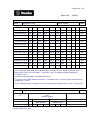
IEC 60335-2-15
Clause
7.2
7.3
Requirement + Test
Result - Remark
Verdict
For kettles : level mark which indicate the rated
capacity (IEC 60335-2-15)
N/A
Unless they cannot be filled beyond their rated
capacity (IEC 60335-2-15)
N/A
Mark outside of the kettle if the level is not self
evident (IEC 60335-2-15)
N/A
Marking on the appliance of the closed position of
the lid of pressure cooker if it is not obvious
(IEC 60335-2-15)
N/A
Identification mark and Model or type reference of
stand for cordless kettles (IEC 60335-2-15)
N/A
Warning for stationary appliances for multiple supply
N/A
Warning placed in vicinity of terminal cover
N/A
Range of rated values marked with the lower and
upper limits separated by a hyphen
220-240V
P
Different rated values marked with the values
separated by an oblique stroke
N/A
7.4
Appliances adjustable for different rated voltages,
the voltage setting is clearly discernible
N/A
7.5
Appliances with more than one rated voltage or one
or more rated voltage ranges, marked with rated
input or rated current for each rated voltage or range,
unless
N/A
the power input is related to the arithmetic mean
value of the rated voltage range
Relation between marking for upper and lower limits
of rated power input or rated current and voltage is
clear
7.6
Correct symbols used
7.7
Connection diagram fixed to appliances to be
connected to more than two supply conductors and
appliances for multiple supply
7.8
Except for type Z attachment, terminals for connection to the supply mains indicated
as follows:
- marking of terminals exclusively for the neutral
conductor (N)
TRF No. IEC60335_2_15E
P
N/A
P
N/A
P
N/A
- Page 7 of 110 -
Report No. 130229
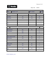
IEC 60335-2-15
Clause
Requirement + Test
Result - Remark
Verdict
- marking of protective earthing terminals (symbol
5019 of IEC 60417)
P
- marking not placed on removable parts
P
7.9
Marking or placing of switches which may cause a
hazard
7.10
Indications of switches on stationary appliances and By the characters & picogram
controls on all appliances by use of figures, letters or near to the knob; and the LED
other visual means ...................................................: indicators;
N/A
P
The figure 0 indicates only OFF position, unless no
confusion with the OFF position
N/A
7.11
Indication for direction of adjustment of controls
N/A
7.12
Instructions for safe use provided
P
The instructions state that:
P
- the appliance is not to be used by children or
persons with reduced physical, sensory or mental
capabilities, or lack of experience and knowledge,
unless they have been given supervision or
instruction
P
- children being supervised not to play with the
appliance
P
Appliance with inlet and intended to be immersed for cleaning: instruction sheet
including in substance : (IEC 60335-2-15)
N/A
- remove connector before cleaning
N/A
- dry appliance inlet before re-use
N/A
The instructions for use for appliances intended to
be used with a connector incorporating a
thermostat, shall state that only the appropriate
connector must be used
N/A
Unless, kettles are constructed so that a hazard cannot arise from boiling water
being ejected, the instructions for use shall include the substance of the following:
N/A
- if the kettle is overfilled, boiling water may be
ejected
N/A
The instructions for use for kettles filled through a lid aperture which is situated
below the handle, shall include the substance of the following warnings :
N/A
Warning: "Position the lid so that steam is directed
away from the handle"
N/A
TRF No. IEC60335_2_15E
- Page 8 of 110 -
Report No. 130229
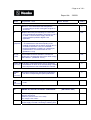
IEC 60335-2-15
Clause
Requirement + Test
Result - Remark
Verdict
Warning: "Do not remove the lid while the water is
boiling"
N/A
Cordless kettles :
N/A
- the instructions for use for cordless kettles shall
state that the kettle is only to be used with the
........................................................stand provided
N/A
- if the kettle and stand of cordless kettles can be
lifted together by gripping the handle of the kettle,
the instructions for use shall include the substance
of the following: "Caution - Ensure that the kettle is
switched off before removing it from its stand"
N/A
The instructions for use for feeding bottle heaters shall state :
N/A
- that the food should not be heated for too long a
period
N/A
- how to check that the correct food temperature
has not been exceeded
N/A
The instructions for use for appliances normally
cleaned after use and not intended to be immersed
in water for cleaning, shall state that the appliance
must not be immersed
P
Pressure cooker :
N/A
The instructions for use for pressure cookers, shall
state that the ducts in the pressure regulator
allowing the escape of steam should be checked
regularly to ensure that they are not blocked
N/A
They shall also give details of how to open the
container safely, and
N/A
state that the container must not be opened until
the pressure has decreased sufficiently
N/A
The instructions for use for egg boilers provided with a pricking device shall contain
the substance of the following :
N/A
Caution: "Avoid injuries from the egg pricker"
N/A
For espresso coffee-makers incorporating a
pressurized reservoir filled by the user, the
instructions shall contain information for the safe
refilling of the water reservoir and the substance of
the following: (A1:2005)
WARNING: The filling aperture must not be opened
during use
TRF No. IEC60335_2_15E
No pressurized reservoir
N/A
N/A
- Page 9 of 110 -
Report No. 130229
IEC 60335-2-15
Clause
Requirement + Test
7.12.1
Sufficient details for installation supplied
N/A
7.12.2
Stationary appliances not fitted with means for
disconnection from the supply mains having a
contact separation in all poles that provide full
disconnection under overvoltage category III, the
instructions state that means for disconnection must
be incorporated in the fixed wiring in accordance with
the wiring rules
N/A
7.12.3
Insulation of the fixed wiring in contact with parts
exceeding 50 K during clause 11; instructions stating
that the fixed wiring must be protected
N/A
7.12.4
Instructions for built-in appliances:
N/A
- dimensions of space
N/A
- dimensions and position of supporting means
N/A
- distances between parts and surrounding structure
N/A
- dimensions of ventilation openings and
arrangement
N/A
- connection to supply mains and interconnection of
separate components
N/A
- allow disconnection of the appliance after
installation, by accessible plug or a switch in the
fixed wiring, unless
N/A
a switch complying with 24.3
N/A
Replacement cord instructions, type X attachment
with a specially prepared cord
N/A
Replacement cord instructions, type Y attachment
P
Replacement cord instructions, type Z attachment
N/A
7.12.6
Caution in the instructions for heating appliances
with a non-self-resetting thermal cut-out
N/A
7.12.7
Instructions for fixed appliances stating how the
appliance is to be fixed
N/A
7.12.8
Instructions for appliances connected to the water mains:
N/A
- max. inlet water pressure (Pa)...............................:
N/A
- min. inlet water pressure, if necessary (Pa) ..........:
N/A
7.12.5
TRF No. IEC60335_2_15E
Result - Remark
Verdict
- Page 10 of 110 -
Report No. 130229
IEC 60335-2-15
Clause
Requirement + Test
Result - Remark
Verdict
N/A
Instructions concerning new and old hose-sets for
appliances connected to the water mains by
detachable hose-sets
English and German
instruction manuals are
checked
P
7.13
Instructions and other texts in an official language
7.14
Marking clearly legible and durable
P
7.15
Marking on a main part
P
Marking clearly discernible from the outside, if
necessary after removal of a cover
P
For portable appliances, cover can be removed or
opened without a tool
N/A
For stationary appliances, name, trademark or
identification mark and model or type reference
visible after installation
N/A
For fixed appliances, name, trademark or
identification mark and model or type reference
visible after installation according to the instructions
N/A
Indications for switches and controls placed on or
near the components. Marking not on parts which
can be positioned or repositioned in such a way that
the marking is misleading
P
N/A
7.16
Marking of a possible replaceable thermal link or
fuse link clearly visible with regard to replacing the
link
8
PROTECTION AGAINST ACCESS TO LIVE PARTS
8.1
Adequate protection against accidental contact with
live parts
P
8.1.1
Requirement applies for all positions, detachable
parts removed
P
Insertion or removal of lamps, protection against
contact with live parts of the lamp cap
N/A
Use of test probe B of IEC 61032: no contact with
live parts
P
Use of test probe 13 of IEC 61032 through openings
in class 0 appliances and class II appliances/
constructions: no contact with live parts
P
8.1.2
TRF No. IEC60335_2_15E
- Page 11 of 110 -
Report No. 130229
IEC 60335-2-15
Clause
Requirement + Test
Result - Remark
N/A
Test probe 13 also applied through openings in
earthed metal enclosures having a non-conductive
coating: no contact with live parts
See Note (IEC 60335-2-15)
Verdict
Connecting device for coffee
mill is checked
P
8.1.3
For appliances other than class II, use of test probe
41 of IEC 61032: no contact with live parts of visible
glowing heating elements
N/A
8.1.4
Accessible part not considered live if:
N/A
- safety extra-low a.c. voltage: peak value not
exceeding 42.4 V
N/A
- safety extra-low d.c. voltage: not exceeding 42.4 V
N/A
- or separated from live parts by protective
impedance
N/A
If protective impedance: d.c. current not exceeding
2 mA, and
N/A
a.c. peak value not exceeding 0.7 mA
N/A
- for peak values over 42.4 V up to and including
450 V, capacitance not exceeding 0,1 μF
N/A
- for peak values over 450 V up to and including
15 kV, discharge not exceeding 45 μC
N/A
- for peak values over 15kV, the energy in the
discharge not exceeding 350 mJ
N/A
Live parts protected at least by basic insulation before installation or assembly:
N/A
- built-in appliances
N/A
- fixed appliances
N/A
- appliances delivered in separate units
N/A
8.1.5
8.2
9
Class II appliances and constructions constructed so
that there is adequate protection against accidental
contact with basic insulation and metal parts
separated from live parts by basic insulation only
P
Only possible to touch parts separated from live
parts by double or reinforced insulation
P
STARTING OF MOTOR-OPERATED APPLIANCES
TRF No. IEC60335_2_15E
- Page 12 of 110 -
Report No. 130229
IEC 60335-2-15
Clause
Requirement + Test
Result - Remark
N/A
This clause of part 1 is not applicable
(IEC 60335-2-15)
10
POWER INPUT AND CURRENT
10.1
Power input at normal operating temperature, rated
voltage and normal operation not deviating from
rated power input by more than shown in table 1
(see appended table)
P
P
Test for an appliance with one or more rated voltage
ranges
10.2
Verdict
Current at normal operating temperature, rated
voltage and normal operation not deviating from
rated current by more than shown in table 2
N/A
Test for an appliance with one or more rated voltage
ranges
N/A
11
HEATING
11.1
No excessive temperatures in normal use
11.2
Placing and mounting of appliance as described
P
Portable appliances are tested away from the walls
of the test corner (IEC 60335-2-15)
P
Temperature rises, other than of windings,
determined by thermocouples
P
11.3
Coffee mill tested in the
APPENDIX 4
Temperature rises of windings determined by
resistance method, unless
11.4
11.5
P
N/A
the windings makes it difficult to make the necessary The winding of water pump
connections
motor
P
Heating appliances operated under normal operation 1753W (255,0V)
at 1.15 times rated power input ..............................:
P
If the temperature rise limits are exceeded in
appliances incorporating motors, transformers or
electronic circuits and if the power input is lower
than the rated power input, the test is repeated with
the appliance supplied at 1,06 times rated voltage
(IEC 60335-2-15)
N/A
Motor-operated appliances operated under normal
operation at most unfavourable voltage between
0.94 and 1.06 times rated voltage ...........................:
N/A
TRF No. IEC60335_2_15E
- Page 13 of 110 -
Report No. 130229
IEC 60335-2-15
Clause
Requirement + Test
11.6
Combined appliances operated under normal
operation at most unfavourable voltage between
0.94 and 1.06 times rated voltage ...........................:
Result - Remark
Verdict
N/A
Combined appliances are tested as heating
appliances (IEC 60335-2-15)
P
11.7
Appliances are operated for the duration specified in
11.7.101 to 11.7.105 (IEC 60335-2-15)
P
11.7.101
For kettles with temperature limiter : test terminated
after second operation of temperature limiter
N/A
For kettles with thermostat : test terminated 15 min
after the water has attained 95° C and 5 min after for
others kettles
N/A
For cooking pans, egg boilers, feeding-bottle heaters, glue pots, livestock feed boilers,
milk heaters, sterilizers, wash boilers and for appliances that boil water other than
kettles, the fest is terminated: (A1:2005)
N/A
- appliances without a thermal control, 15 min after
the water in the container has attained a temperature
of 95 °C or the maximum temperature it can attain if
this is lower
N/A
- portable appliances : 15 min after the thermal
control has operated for the first time
N/A
- fixed appliances : 30 min after the thermal control
has operated for the first time
N/A
- appliances with acoustic signal : 1 min after signal
N/A
For appliances having heated surface for keeping
the liquid warm : also until steady conditions with and
without the container
N/A
Slow cookers, steam cookers and yoghurt makers
are operated until steady conditions are established
N/A
Slow cookers are prewarmed in the dry state if this
instruction is given
N/A
11.7.102
11.7.103
11.7.104
Espresso coffee-makers are operated in accordance
with the instructions for use
P
Espresso coffee-makers having an outlet for
supplying steam or hot water, before each rest
period the brewing period is immediately followed by
a period during which the steam or water is
supplied for the time indicated in the instructions
P
TRF No. IEC60335_2_15E
- Page 14 of 110 -
Report No. 130229
IEC 60335-2-15
Clause
Requirement + Test
Result - Remark
P
Espresso coffee-makers operated until steady
conditions
11.7.105
Pressure cookers operated 15 min after attaining the
maximum cooking pressure
11.8
Temperature rises not exceeding values in table 3
Verdict
N/A
(see appended tables)
P
Sealing compound does not flow out
P
Protective devices do not operate, except
P
components in protective electronic circuits tested for
the number of cycles specified in 24.1.4
N/A
When an appliance connector incorporates a
thermostat, the temperature rise limit for the pins of
the inlet does not apply (IEC 60335-2-15)
N/A
The temperature rise limits of motors, transformers,
components of electronic circuit and parts directly
influenced by them may be exceeded when the
appliance is operated at 1,15 times rated power
input (IEC 60335-2-15)
N/A
13
LEAKAGE CURRENT AND ELECTRIC STRENGTH AT OPERATING
TEMPERATURE
13.1
Leakage current not excessive and electric strength
adequate
P
Heating appliances operated at 1.15 times rated
power input ...............................................................:
N/A
Motor-operated appliances and combined
appliances supplied at 1.06 times rated voltage .....:
13.2
P
Leakage current measured by means of the circuit
described in figure 4 of IEC 60990
P
(see appended table)
No breakdown during the tests
TRANSIENT OVERVOLTAGES
TRF No. IEC60335_2_15E
P
P
The appliance is disconnected from the supply
Electric strength tests according to table 4
14
P
Protective impedance and radio interference filters
disconnected before carrying out the tests
Leakage current measurements
13.3
254,4V
(see appended table)
P
P
- Page 15 of 110 -
Report No. 130229
IEC 60335-2-15
Clause
Requirement + Test
Result - Remark
Verdict
Appliances withstand the transient overvoltages to
which they may be subjected
N/A
Clearances having a value less than specified in
table 16 subjected to an impulse voltage test, the test
voltage specified in table 6
N/A
No flashover during the test, unless of functional
insulation
N/A
In case of flashover of functional insulation, the
appliance complies with clause 19 with the clearance
short circuited
N/A
15
MOISTURE RESISTANCE
15.1
Enclosure provides the degree of moisture protection IPX0
according to classification of the appliance
N/A
Compliance checked as specified in 15.1.1, taking
into account 15.1.2, followed by the electric strength
test of 16.3
N/A
No trace of water on insulation which can result in a
reduction of clearances and creepage distances
below values specified in clause 29
N/A
Appliances, other than IPX0, subjected to tests as
specified in IEC 60529 .............................................:
N/A
Water valves in external hoses for connection of an
appliance to the water mains tested as specified for
IPX7 appliances
N/A
Hand-held appliance turned continuously through the
most unfavourable positions during the test
N/A
Built-in appliances installed according to the
instructions
N/A
Appliances placed or used on the floor or table
placed on a horizontal unperforated support
N/A
Appliances normally fixed to a wall and appliances
with pins for insertion into socket-outlets are
mounted on a wooden board
N/A
For IPX3 appliances, the base of wall mounted
appliances is placed at the same level as the pivot
axis of the oscillating tube
N/A
15.1.1
15.1.2
TRF No. IEC60335_2_15E
- Page 16 of 110 -
Report No. 130229
IEC 60335-2-15
Clause
15.2
Requirement + Test
Result - Remark
Verdict
For IPX4 appliances, the horizontal centre line of the
appliance is aligned with the pivot axis of the
oscillating tube
N/A
However, for appliances normally used on the floor
or table, the movement is limited to two times 90° for
a period of 5 min, the support being placed at the
level of the pivot axis of the oscillating tube
N/A
Appliances normally fixed to a ceiling are mounted
underneath a horizontal unperforated support, the
pivot axis of the oscillating tube located at the level of
the underside of the support
N/A
For IPX4 appliances, the movement of the tube is
limited to two times 90° from the vertical for a period
of 5 min
N/A
Wall-mounted appliances, take into account the
distance to the floor stated in the instructions
N/A
Appliances with type X attachment fitted with a
flexible cord as described
N/A
Detachable parts tested as specified
N/A
P
Spillage of liquid does not affect the electrical
insulation
Appliances with type X attachment fitted with a
flexible cord as described
N/A
Appliances incorporating an appliance inlet tested
with or without an connector, whichever is most
unfavourable
N/A
P
Detachable parts removed
Overfilling test with additional amount of
water, over a period of 1 min (l) ...............................:
0,25 l
P
The appliance withstands the electric strength test of
16.3
P
No trace of water on insulation that can result in a
reduction of clearances and creepage distances
below values specified in clause 29
P
The test is only carried out with the appliance
connector in position (IEC 60335-2-15)
Connecting device for coffee
mill checked
P
spillage tests with a deviation (°) from the normal
position:
5°
P
TRF No. IEC60335_2_15E
- Page 17 of 110 -
Report No. 130229
IEC 60335-2-15
Clause
15.101
15.102
15.3
Requirement + Test
Result - Remark
Verdict
Steam sterilizers : particular overfilling test in
conditions as specified (A1:2005)
N/A
Cordless kettles : particular overfilling test in
conditions as specified (A1:2005)
N/A
Kettles : particular overfilling test in conditions as
specified (A1:2005)
N/A
Appliances to be immersed in water for cleaning
sufficiently protected against effects of immersion
N/A
Testing conditions and scheduling as specified
N/A
No trace of water on insulation which can result in
reduction of creepage distances and clearance
below values specified in 29
N/A
Cordless kettles : particular electric strength test in
conditions as specified
N/A
Stand withstanding the test of 16.3 with voltage
reduced to 2500 V for reinforced insulation
N/A
P
Appliances proof against humid conditions
Humidity test for 48 h in a humidity cabinet
25°C; 95%
P
P
The appliance withstands the tests of clause 16
16
LEAKAGE CURRENT AND ELECTRIC STRENGTH
16.1
Leakage current not excessive and electric strength
adequate
P
Protective impedance disconnected from live parts
before carrying out the tests
N/A
16.2
Single-phase appliances: test voltage 1.06 times
rated voltage.............................................................:
254,4V
N/A
Three-phase appliances: test voltage 1.06 times
rated voltage divided by √3 ......................................:
16.3
Leakage current measurements
(see appended table)
P
Electric strength tests according to table 7
(see appended table)
P
No breakdown during the tests
17
P
P
OVERLOAD PROTECTION OF TRANSFORMERS AND ASSOCIATED CIRCUITS
No excessive temperatures in transformer or
associated circuits in event of short-circuits likely to
occur in normal use
TRF No. IEC60335_2_15E
N/A
- Page 18 of 110 -
Report No. 130229
IEC 60335-2-15
Clause
18
Requirement + Test
Result - Remark
Verdict
Appliance supplied with 1.06 or 0.94 times rated
voltage and the most unfavourable short-circuit or
overload likely to occur in normal use applied.........:
N/A
Temperature rise of insulation of the conductors of
safety extra-low voltage circuits not exceeding the
relevant value specified in table 3 by more than 15 K
N/A
Temperature of the winding not exceeding the value
specified in table 8,
N/A
however limits do not apply to fail-safe transformers
complying with sub-clause 15.5 of IEC 61558-1
N/A
ENDURANCE
N/A
This clause of part 1 is not applicable
(IEC 60335-2-15)
19
ABNORMAL OPERATION
19.1
The risk of fire or mechanical damage under
abnormal or careless operation obviated
P
Electronic circuits so designed and applied that a
fault will not render the appliance unsafe
P
19.2
Appliances incorporating contactors or relays
subjected to the test of 19.14, being carried out
before the tests of 19.11
N/A
Kettles are not subjected to the test of 19.2
(IEC 60335-2-15)
N/A
Kettles checked by 19.101, unless the appliance
incorporates a non-self resetting thermal cut-out
(IEC 60335-2-15)
N/A
Kettles compliance with 19.101 relies on the
operation of a self resetting thermal cut-out are
subjected 19.102 (IEC 60335-2-15)
N/A
Test of appliance with heating elements with
restricted heat dissipation; test voltage (V): power
input of 0.85 times rated power input ......................:
217V; 1089W
P
Appliances are placed as near as possible to the
walls of the test corner (IEC 60335-2-15)
They are tested empty with lids open or closed
whichever is the more unfavourable
(IEC 60335-2-15)
TRF No. IEC60335_2_15E
P
No lid
N/A
- Page 19 of 110 -
Report No. 130229
IEC 60335-2-15
Clause
Requirement + Test
Result - Remark
19.3
Test of 19.2 repeated; test voltage (V): power input
of 1.24 times rated power input ...............................:
264V; 1890W
19.4
19.5
19.6
19.7
Verdict
P
Kettles are operated empty at 1.15 times rated
power input (IEC 60335-2-15)
N/A
The test is carried out with the kettle filled with
sufficient water to cover the heating element or if
the heating element is not positioned inside the
container, to a depth of 10 mm : (IEC 60335-2-15)
N/A
Test conditions as in cl. 11, any control limiting the
temperature during tests of cl. 11 short-circuited
P
Pressure regulators of pressure cookers are
rendered inoperative together with each protective
device in turn (IEC 60335-2-15)
N/A
Test of 19.4 repeated on Class 0I and I appliances
with tubular sheathed or embedded heating
elements. No short-circuiting, but one end of the
element connected to the elements sheath
P
The test repeated with reversed polarity and the
other end of the heating element connected to the
sheath
P
The test is not carried out on appliances intended to
be permanently connected to fixed wiring and on
appliances where an all-pole disconnection occurs
during the test of 19.4
N/A
Appliances with PTC heating elements tested at
rated voltage, establishing steady conditions
N/A
The working voltage of the PTC heating element is
increased by 5% and the appliance is operated until
steady conditions are re-established. The voltage is
then increased in similar steps until 1.5 times
working voltage or until the PTC heating element
ruptures
N/A
Stalling test by locking the rotor if the locked rotor
torque is smaller than the full load torque or locking
moving parts of other appliances
P
Locked rotor, motor capacitors open-circuited or
short-circuited, if required
N/A
Locked rotor, capacitors open-circuited one at a time
N/A
TRF No. IEC60335_2_15E
- Page 20 of 110 -
Report No. 130229
IEC 60335-2-15
Clause
Requirement + Test
Result - Remark
Verdict
Test repeated with capacitors short-circuited one at a
time, if required
N/A
Appliances with timer or programmer supplied with
rated voltage for each of the tests, for a period equal
to the maximum period allowed
N/A
Other appliances supplied with rated voltage for a
period as specified
N/A
P
Espresso coffee-makers are operated for a period
of 5 min (IEC 60335-2-15)
Winding temperatures not exceeding values
specified in table 8
(see appended table)
P
19.8
Three-phase motors operated at rated voltage with
one phase disconnected
N/A
19.9
Running overload test on appliances incorporating
motors intended to be remotely or automatically
controlled or liable to be operated continuously
N/A
Winding temperatures not exceeding values as
specified
N/A
19.10
Series motor operated at 1.3 times rated voltage for
1 min .........................................................................:
Coffee mill tested in Appendix
4
N/A
During the test, parts not being ejected from the
appliance
19.11
Electronic circuits, compliance checked by
evaluation of the fault conditions specified in 19.11.2
for all circuits or parts of circuits, unless they comply
with the conditions specified in 19.11.1
P
Appliances incorporating a protective electronic
circuit subjected to the tests of 19.11.3 and 19.11.4
N/A
Appliances having a switch with an off position
obtained by electronic disconnection, or a switch
placing the appliance in a stand-by mode, subjected
to the tests of 19.11.4
Not possible unsafe operation
Appliances incorporating an electronic circuit that
relies upon a programmable component to function
correctly, subjected to the test of 19.11.4.8
19.11.1
N/A
Before applying the fault conditions a) to f) in 19.11.2, it is checked if circuits or parts
of circuit meet both of the following conditions:
TRF No. IEC60335_2_15E
P
N/A
P
- Page 21 of 110 -
Report No. 130229
IEC 60335-2-15
Clause
19.11.2
Requirement + Test
Result - Remark
Verdict
- the electronic circuit is a low-power circuit, that is,
the maximum power at low-power points does not
exceed 15 W according to the tests specified
After T4(78L05)
P
- the protection against electric shock, fire hazard,
mechanical hazard or dangerous malfunction in
other parts of the appliance does not rely on the
correct functioning of the electronic circuit
P
Fault conditions applied one at a time, the appliance operated under conditions
specified in cl. 11, but supplied at rated voltage, the duration of the tests as specified:
P
a) short circuit of functional insulation if clearances or
creepage distances are less than the values
specified in 29
19.11.3
N/A
b) open circuit at the terminals of any component
P
c) short circuit of capacitors, unless they comply with
IEC 60384-14
P
d) short circuit of any two terminals of an electronic
component, other than integrated circuits. This fault
condition is not applied between the two circuits of
an optocoupler
P
e) failure of triacs in the diode mode
P
f) failure of an integrated circuit
P
g) failure of an electronic power switching device
P
If the appliance incorporates a protective electronic
circuit which operates to ensure compliance with
clause 19, the relevant test is repeated with a single
fault simulated, as indicated in a) to f) of 19.11.2
N/A
During and after each test the following is checked:
P
- the temperature rise of the windings do not exceed
the values specified in table 8
P
- the appliance complies with the conditions specified
in 19.13
P
- any current flowing through protective impedance
not exceeding the limits specified in 8.1.4
N/A
If a conductor of a printed board becomes open-circuited, the appliance is considered
to have withstood the particular test, provided all three of the following conditions are
met:
N/A
TRF No. IEC60335_2_15E
- Page 22 of 110 -
Report No. 130229
IEC 60335-2-15
Clause
19.11.4
Requirement + Test
Result - Remark
Verdict
- the material of the printed circuit board withstands
the burning test of annex E
N/A
- any loosened conductor does not reduce the
clearances or creepage distances between live parts
and accessible metal parts below the values
specified in cl. 29
N/A
- the appliance withstands the tests of 19.11.2 with
open-circuited conductor bridged
N/A
P
Appliances having a device with an off position
obtained by electronic disconnection, or
N/A
a device that can be placed in the stand-by mode,
subjected to the tests of 19.11.4.1 to 19.11.4.7
Not possible unsafe operation
P
Appliances incorporating a protective electronic
circuit subjected to the tests of 19.11.4.1 to
19.11.4.7, except that
N/A
appliances operated for 30 s or 5 min during the test
of 19.7 are not subjected to the tests for
electromagnetic phenomena.
N/A
19.11.4.1
The appliance is subjected to electrostatic
discharges in accordance with IEC 61000-4-2, test
level 4
P
19.11.4.2
The appliance is subjected to radiated fields in
accordance with IEC 61000-4-3, test level 3
P
19.11.4.3
The appliance is subjected to fast transient bursts in
accordance with IEC 61000-4-4, test level 3 or 4 as
specified
P
19.11.4.4
The power supply terminals of the appliance
subjected to voltage surges in accordance with IEC
61000-4-5, test level 3 or 4 as specified
P
Earthed heating elements in class I appliances
disconnected
P
19.11.4.5
The appliance is subjected to injected currents in
accordance with IEC 61000-4-6, test level 3
P
19.11.4.6
The appliance is subjected to the Class 3 voltage
dips and interruptions in accordance with IEC 610004-11
P
TRF No. IEC60335_2_15E
- Page 23 of 110 -
Report No. 130229
IEC 60335-2-15
Clause
Requirement + Test
19.11.4.7
The appliance is subjected to mains signals in
accordance with IEC 61000-4-13, test level class 2
P
19.11.4.8
The appliance is supplied at rated voltage and
operated under normal operation. After 60s the
power supply is reduces to a level such that the
appliance ceases to respond or a programmable
component cease to operate.
P
The appliance continues to operate normally or
requires a manual operation to restart
P
19.12
If the safety of the appliance for any of the fault
conditions specified in 19.11.2 depends on the
operation of a miniature fuse-link complying with
IEC 60127, the test is repeated, measuring the
current flowing through the fuse-link; measured
current (A); rated current of the fuse-link (A)...........:
19.13
During the tests the appliance does not emit flames,
molten metal, poisonous or ignitable gas in
hazardous amounts
Temperature rises not exceeding the values shown
in table 9
Result - Remark
>30A; 10A
Verdict
P
P
(see appended table)
P
P
Compliance with cl. 8 not impaired
N/A
If the appliance can still be operated it complies with
20.2
Insulation, other than of class III appliance, withstand the electric strength test of 16.3,
the test voltage specified in table 4:
P
- basic insulation.......................................................:
P
1000V
N/A
- supplementary insulation .......................................:
- reinforced insulation...............................................:
3000V
P
After operation or interruption of a control,
clearances and creepage distances across the
functional insulation withstanding the electric
strength test of 16.3. the test voltage being twice the
working voltage
P
The appliance does not undergo a dangerous
malfunction, and
P
no failure of protective electronic circuits, if the
appliance is still operable
N/A
TRF No. IEC60335_2_15E
- Page 24 of 110 -
Report No. 130229
IEC 60335-2-15
Clause
Requirement + Test
Result - Remark
Verdict
Appliances tested with an electronic switch in the off position, or in the stand-by
mode:
P
- do not become operational, or
P
- if they become operational, do not result in a
dangerous malfunction during or after the tests of
19.11.4
P
During the test of 19.4, pressure relief devices of
pressure cookers operate before pressure has
reached 350 kPa (IEC 60335-2-15)
N/A
19.14
Appliances operated under the conditions of Clause
11. Contactors or relays contacts operating under
the conditions of clause 11 short-circuited
N/A
19.101
Kettle operated empty at 0,85 times or 1,15 times
rated power input, whichever is more unfavourable,
thermal cut-out rendered inoperative
N/A
Any flames keep within the enclosure of the kettle
and supporting surface does not ignite
N/A
19.102
Test with one of the thermal cut-outs rendered
inoperative, carried out 100 times
N/A
19.103
Appliances with detachable liquid containers :
automatic transfer of liquid from one container to
another is liable and safe
Only one detachable liquid
container
N/A
One cycle operation with liquid container and pipes
incorrectly positioned or removed
N/A
Electric strength test
N/A
No trace of water on insulation which can result in
reduction of creapage distance and clearance below
values specified in 29.1
N/A
20
STABILITY AND MECHANICAL HAZARDS
20.1
Adequate stability
P
Tilting test through an angle of 10° (appliance placed
on an inclined plane/horizontal plane); appliance
does not overturn
P
Tilting test repeated on appliances with heating
elements, angle of inclination increased to 15°
P
TRF No. IEC60335_2_15E
- Page 25 of 110 -
Report No. 130229
IEC 60335-2-15
Clause
Requirement + Test
Result - Remark
N/A
Possible heating test in overturned position;
temperature rise does not exceed values shown in
table 9
20.2
Verdict
Moving parts adequately arranged or enclosed as to Coffee mill tested in the
provide protection against personal injury
APPENDIX 4
P
Protective enclosures, guards and similar parts are
non-detachable
P
Adequate mechanical strength and fixing of
protective enclosures
P
N/A
Self-resetting thermal cut-outs and overcurrent
protective devices not causing a hazard, by
unexpected reclosure
P
Not possible to touch dangerous moving parts with
test probe
21
MECHANICAL STRENGTH
21.1
Appliance has adequate mechanical strength and is
constructed as to withstand rough handling
P
Checked by applying blows to the appliance in
accordance with test Ehb of IEC 60068-2-75, spring
hammer test, impact energy 0,5 J
P
If necessary, supplementary or reinforced insulation
subjected to the electric strength test of 16.3
N/A
If necessary, repetition of groups of three blows on a
new sample
N/A
See Note (IEC 60335-2-15)
N/A
21.2
Accessible parts of solid insulation having strength to
prevent penetration by sharp implements
P
The insulation is tested as specified, unless
the thickness of supplementary insulation is at least
1 mm and reinforced insulation is at least 2 mm
N/A
Min. thickness of enclosure:
2,9mm
P
22
CONSTRUCTION
22.1
Appliance marked with the first numeral of the IP
system, relevant requirements of IEC 60529 are
fulfilled
N/A
22.2
Stationary appliance: means to provide all-pole disconnection from the supply
provided, the following means being available:
N/A
TRF No. IEC60335_2_15E
- Page 26 of 110 -
Report No. 130229
IEC 60335-2-15
Clause
22.3
Requirement + Test
Result - Remark
Verdict
- a supply cord fitted with a plug
N/A
- a switch complying with 24.3
N/A
- a statement in the instruction sheet that a
disconnection incorporated in the fixed wiring is to be
provided
N/A
- an appliance inlet
N/A
Singe-pole switches and single-pole protective
devices for the disconnection of heating elements in
single-phase, permanently connected class 01 and
class I appliances, connected to the phase
conductor
N/A
Appliance provided with pins: no undue strain on
socket-outlets
N/A
Applied torque not exceeding 0.25 Nm
N/A
Pull force of 50N to each pin after the appliance has
being placed in the heating cabinet; when cooled to
room temperature the pins are not displaced by
more than 1mm
N/A
Each pin subjected to a torque of 0.4Nm; the pins
are not rotating unless rotating does not impair
compliance with the standard
N/A
22.4
Appliance for heating liquids and appliance causing
undue vibration not provided with pins for insertion
into socket-outlets
P
22.5
No risk of electric shock when touching the pins of
the plug, for appliances having a capacitor with rated
capacitance exceeding 0,1μF, the appliance being
disconnected from the supply at the instant of
voltage peak
P
22.6
Electrical insulation not affected by condensing water
or leaking liquid
P
Electrical insulation of Class II appliances not
affected in case of a hose rupture or seal leak
P
Drain holes shall be at least 5 mm in diameter or
20 mm² in area with a width of at least 3 mm
(IEC 60335-2-15)
TRF No. IEC60335_2_15E
705 mm² in area with a width
of 4,7mm
P
- Page 27 of 110 -
Report No. 130229
IEC 60335-2-15
Clause
Requirement + Test
Result - Remark
22.7
Adequate safeguards against the risk of excessive
pressure in appliances provided with steamproducing devices
N/A
Additional test for espresso coffee-maker : (IEC 60335-2-15)
N/A
Max. pressure obtained with coffee filter blocked
and any steam valve closed; test 5 min with twice
this max. pressure :
N/A
No pressure container
Verdict
No rupture, no abnormal leakage; appliance fit for
further use
N/A
Max. pressure test with pressure limiting devices
made ineffective
N/A
No explosion nor emission of dangerous jets of
steam
N/A
Last test repeated in case of rupture of an
intentionally weak part: the appliance shall be
terminated in the same mode
N/A
Pressure cooker test with six times the max.
nominal cooking pressure
N/A
No rupture of container
N/A
22.8
Electrical connections not subject to pulling during
cleaning of compartments to which access can be
gained without the aid of a tool, and that are likely to
be cleaned in normal use
N/A
22.9
Insulation, internal wiring, windings, commutators
and slip rings not exposed to oil, grease or similar
substances
P
Adequate insulating properties of oil or grease to
which insulation is exposed
N/A
Not possible to reset voltage-maintained non-selfresetting thermal cut-outs by the operation of an
automatic switching device incorporated within the
appliance
N/A
Non-self resetting thermal motor protectors have a
trip-free action, unless
N/A
they are voltage maintained
N/A
22.10
TRF No. IEC60335_2_15E
- Page 28 of 110 -
Report No. 130229
IEC 60335-2-15
Clause
22.11
22.12
Requirement + Test
Result - Remark
Verdict
Location or protection of reset buttons of non-selfresetting controls is so that accidental resetting is
unlikely
N/A
Reliable fixing of non-detachable parts that provide
the necessary degree of protection against electric
shock, moisture or contact with moving parts
P
Obvious locked position of snap-in devices used for
fixing such parts
P
No deterioration of the fixing properties of snap-in
devices used in parts that are likely to be removed
during installation or servicing
P
Tests as described
P
Handles, knobs etc. fixed in a reliable manner
P
Fixing in wrong position of handles, knobs etc.
indicating position of switches or similar components
not possible
P
Axial force 15 N applied to parts, the shape being so Function selection knob
that an axial pull is unlikely to be applied
P
Axial force 30 N applied to parts, the shape being so
that an axial pull is likely to be applied
N/A
22.13
Unlikely that handles, when gripped as in normal
use, make the operators hand touch parts having a
temperature rise exceeding the value specified for
handles which are held for short periods only
P
22.14
No ragged or sharp edges creating a hazard for the
user in normal use, or during user maintenance
P
No exposed pointed ends of self tapping screws etc.,
liable to be touched by the user in normal use or
during user maintenance
P
22.15
Storage hooks and the like for flexible cords smooth
and well rounded
N/A
22.16
Automatic cord reels cause no undue abrasion or
damage to the sheath of the flexible cord, no
breakage of conductors strands, no undue wear of
contacts
N/A
Cord reel tested with 6000 operations, as specified
N/A
TRF No. IEC60335_2_15E
- Page 29 of 110 -
Report No. 130229
IEC 60335-2-15
Clause
Requirement + Test
Result - Remark
Verdict
Electric strength test of 16.3, voltage of 1000 V
applied
N/A
22.17
Spacers not removable from the outside by hand or
by means of a screwdriver or a spanner
N/A
22.18
Current-carrying parts and other metal parts resistant
to corrosion under normal conditions of use
22.19
Driving belts not used as electrical insulation
N/A
22.20
Direct contact between live parts and thermal
insulation effectively prevented, unless material used
is non-corrosive, non-hygroscopic and noncombustible
N/A
Compliance is checked by inspection and, if
necessary, by appropriate test
N/A
Wood, cotton, silk, ordinary paper and fibrous or
hygroscopic material not used as insulation, unless
impregnated
N/A
22.21
P
This requirement does not apply to magnesium
oxide and mineral ceramic fibres used for the
electrical insulation of heating elements
P
22.22
Appliances not containing asbestos
P
22.23
Oils containing polychlorinated biphenyl (PCB) not
used
N/A
22.24
Bare heating elements adequately supported
N/A
In case of rupture, the heating conductor is unlikely
to come in contact with accessible metal parts
N/A
22.25
Sagging heating conductors cannot come into
contact with accessible metal parts
N/A
22.26
The insulation between parts operating at safety
extra-low voltage and other live parts complies with
the requirements for double or reinforced insulation
N/A
22.27
Parts connected by protective impedance separated
by double or reinforced insulation
N/A
22.28
Metal parts of Class II appliances conductively
connected to gas pipes or in contact with water:
separated from live parts by double or reinforced
insulation
N/A
TRF No. IEC60335_2_15E
- Page 30 of 110 -
Report No. 130229
IEC 60335-2-15
Clause
Requirement + Test
22.29
Class II appliances permanently connected to fixed
wiring so constructed that the required degree of
access to live parts is maintained after installation
22.30
Parts serving as supplementary or reinforced
insulation fixed so that they cannot be removed
without being seriously damaged, or
P
so constructed that they cannot be replaced in an
incorrect position, and so that if they are omitted, the
appliance is rendered inoperable or manifestly
incomplete
P
Clearances and creepage distances over
supplementary and reinforced insulation not reduced
below values specified in clause 29 as a result of
wear
P
Clearances and creepage distances between live
parts and accessible parts not reduced below values
for supplementary insulation, if wires, screws etc.
become loose
P
Supplementary and reinforced insulation designed or
protected against deposition of dirt or dust
P
22.31
22.32
22.33
Result - Remark
Verdict
N/A
Supplementary insulation of natural or synthetic
rubber resistant to ageing, or arranged and
dimensioned so that creepage distances are not
reduced below values specified in 29.2
N/A
Ceramic material not tightly sintered, similar material
or beads alone not used as supplementary or
reinforced insulation
N/A
Oxygen bomb test at 70 °C for 96 h and 16 h at room
temperature
N/A
Insulating material in which heating conductors are
embedded is considered to be basic insulation and
not reinforced insulation
P
Conductive liquids that are or may become
accessible in normal use are not in direct contact
with live parts
P
Electrodes not used for heating liquids
For class II constructions, conductive liquids that are
or may become accessible in normal use, not in
direct contact with basic or reinforced insulation
TRF No. IEC60335_2_15E
No electrodes
P
P
- Page 31 of 110 -
Report No. 130229
IEC 60335-2-15
Clause
Requirement + Test
For class II constructions, conductive liquids which
are in contact with live parts, not in direct contact
with reinforced insulation
Result - Remark
Verdict
N/A
22.34
Shafts of operating knobs, handles, levers etc. not
live, unless the shaft is not accessible when the part
is removed
P
22.35
Handles, levers and knobs, held or actuated in
normal use, not becoming live in the event of a
failure of basic insulation
P
Such parts being of metal, and their shafts or fixings
are likely to become live in the event of a failure of
basic insulation, are either adequately covered by
insulation material or their accessible parts are
separated from their shafts or fixings by
supplementary insulation
N/A
This requirement does not apply to handles, levers
and knobs on stationary appliances other than those
of electrical components, provided they are either
reliably connected to an earthing terminal or earthing
contact, or separated from live parts by earthed
metal
N/A
22.36
Handles continuously held in the hand in normal use
are so constructed that when gripped as in normal
use, the operators hand is not likely to touch metal
parts, unless they are separated from live parts by
double or reinforced insulation
N/A
22.37
Capacitors in Class II appliances not connected to
accessible metal parts, unless complying with 22.42
N/A
Metal casings of capacitors in Class II appliances
separated from accessible metal parts by
supplementary insulation, unless complying with
22.42
N/A
22.38
Capacitors not connected between the contacts of a
thermal cut-out
P
22.39
Lamp holders used only for the connection of lamps
N/A
22.40
Motor-operated appliances and combined
appliances intended to be moved while in operation,
or having accessible moving parts, fitted with a
switch to control the motor. The actuating member of
the switch being easily visible and accessible
N/A
TRF No. IEC60335_2_15E
- Page 32 of 110 -
Report No. 130229
IEC 60335-2-15
Clause
Requirement + Test
Unless the appliance can operate continuously,
automatically or remotely without giving rise to a
hazard, appliances for remote operation being fitted
with a switch. The actuating member of the switch
being easily visible and accessible.
Result - Remark
Verdict
N/A
22.41
No components, other than lamps, containing
mercury
22.42
Protective impedance consisting of at least two
separate components
N/A
Values specified in 8.1.4 not exceeded if any one of
the components are short-circuited or open-circuited
N/A
22.43
Appliances adjustable for different voltages,
accidental changing of the setting of the voltage
unlikely to occur
N/A
22.44
Appliances shall not have an enclosure that is
shaped or decorated like a toy
P
22.45
When air is used as reinforced insulation, clearances
not reduced below the values specified in 29.1.4 due
to deformation as a result of an external force
applied to the enclosure
P
22.46
Software used in protective electronic circuits is
software class B or C ..............................................:
N/A
22.47
Appliances connected to the water mains withstand
the water pressure expected in normal use
N/A
No leakage from any part, including any inlet water
hose
N/A
22.48
Appliances connected to the water mains
constructed to prevent backsiphonage of nonpotable water
N/A
22.49
For remote operation, the duration of operation shall
be set before the appliance can be started, unless
N/A
the appliance switches off automatically or can
operate continuously without hazard
N/A
22.50
Controls incorporated in the appliance take priority
over controls actuated by remote operation
N/A
22.51
A control on the appliance being manually adjusted
to the setting for remote operation before the
appliance can be operated in this mode
N/A
TRF No. IEC60335_2_15E
P
- Page 33 of 110 -
Report No. 130229
IEC 60335-2-15
Clause
Requirement + Test
Result - Remark
Verdict
There is a visual indication showing that the
appliance is adjusted for remote operation
N/A
Manual setting and visual indication not necessary on appliances that can operate as
follows, without giving rise to a hazard:
N/A
- operate continuously,
N/A
- operate automatically, or
N/A
- be operated remotely
N/A
22.52
Socket-outlets on appliances accessible to the user
in accordance with the socket-outlet system used in
the country in which the appliance is sold
N/A
22.101
Kettles shall be constructed so that the lid does not
fall off when water is poured out
N/A
22.102
Kettles so constructed that there are no sudden jets
of steam or hot water likely to expose the user to a
hazard when the appliance is used as in normal
use
N/A
22.103
Appliance coupler of cordless kettles shall be
constructed to withstand the stresses occurring
during normal use
Connecting device for coffee
mill is checked
P
Additional test for cordless kettles
Connecting device for coffee
mill is checked
P
The kettle is inserted into and withdrawn from the
stand 10 000 times (1,1 times the rated current)
(10 times per min)
0,39A (the rated current for
coffee mill is 0,35A at 240V)
P
The test is continued for a further 10 000 times
without current flowing
Connecting device for coffee
mill is checked
P
The kettle shall be fit for further use and
compliance with 8.1, 16.3, 27.5 and 29.1 shall not
be impaired
Connecting device for coffee
mill is checked
P
22.104
Portable appliance in which water boil with a
container greater than 3 l is filled to its rated capacity
with the lid closed in accordance with instructions for
use
N/A
The plane is slowly inclined to an angle of 25 ° ; if the
appliance overturns, it is left in this position for 10 s
and then returned to its normal position
N/A
TRF No. IEC60335_2_15E
- Page 34 of 110 -
Report No. 130229
IEC 60335-2-15
Clause
22.105
Requirement + Test
Result - Remark
Verdict
The rate of discharge of liquid does not exceed 16
l/min
N/A
Fixed appliances for boiling water
N/A
Container always open to the atmosphere
N/A
Drain hole: diameter 5 mm, or area 20 mm² with
a width 3 mm
N/A
Aperture not likely to be obstructed in normal use
N/A
If the appliance has provisions for discharging
steam or water overflowing, the discharge aperture
shall be at the base of the appliance and shall
discharge vertically downwards
N/A
Espresso coffee-maker: impossible to remove the
filter by a simple operation while hazardous
pressure within the container
22.107
Pressure cookers shall incorporate a non-selfresetting pressure or temperature responsive
pressure relief device
N/A
22.108
Pressure cooker: not possible to remove the lid
when the inner pressure is excessive
N/A
Pressure test at 4 kPa and 100 N
N/A
No hazardous displacement of lid at removal
N/A
22.109
Feeding-bottle heater: visible or audible signal to
indicate the end of the heating period
N/A
22.109
Kettles constructed so that they are no sudden jets
of steam or hot water likely to expose the user to a
hazard
N/A
22.110
Espresso coffee-makers, incorporating a
pressurized reservoir filled by the user, shall be
constructed so that there is no spillage of water or
sudden jets of steam or hot water (A1:2005)
N/A
When removing the filling cap of the pressurized
reservoir, before the cap is removed completely,
the pressure shall be relieved in a controlled manner
(A1:2005)
N/A
Compliance is checked by inspection during the test
(A1:2005)
N/A
23
INTERNAL WIRING
TRF No. IEC60335_2_15E
No hazardous pressure within
container
N/A
22.106
- Page 35 of 110 -
Report No. 130229
IEC 60335-2-15
Clause
Requirement + Test
23.1
Wireways smooth and free from sharp edges
P
Wires protected against contact with burrs, cooling
fins etc.
P
Wire holes in metal well rounded or provided with
bushings
N/A
Wiring effectively prevented from coming into contact
with moving parts
N/A
Beads etc. on live wires cannot change their
position, and are not resting on sharp edges or
corners
N/A
Beads inside flexible metal conduits contained within
an insulating sleeve
N/A
Electrical connections and internal conductors
movable relatively to each other not exposed to
undue stress
N/A
Flexible metallic tubes not causing damage to
insulation of conductors
N/A
Open-coil springs not used
N/A
Adequate insulating lining provided inside a coiled
spring, the turns of which touch one another
N/A
No damage after 10 000 flexings for conductors
flexed during normal use or 100 flexings for
conductors flexed during user maintenance
N/A
Electric strength test, 1000 V between live parts and
accessible metal parts
N/A
23.4
Bare internal wiring sufficiently rigid and fixed
N/A
23.5
The insulation of internal wiring withstanding the
electrical stress likely to occur in normal use
P
No breakdown when a voltage of 2000 V is applied
for 15 min between the conductor and metal foil
wrapped around the insulation
P
23.6
Sleeving used as supplementary insulation on
internal wiring retained in position by positive means
N/A
23.7
The colour combination green/yellow used only for
earthing conductors
P
23.8
Aluminium wires not used for internal wiring
P
23.2
23.3
TRF No. IEC60335_2_15E
Result - Remark
Verdict
- Page 36 of 110 -
Report No. 130229
IEC 60335-2-15
Clause
Requirement + Test
23.9
No lead-tin soldering of stranded conductors where
they are subject to contact pressure, unless
P
clamping means so constructed that there is no risk
of bad contact due to cold flow of the solder
N/A
23.10
The insulation and sheath of internal wiring,
incorporated in external hoses for the connection of
an appliance to the water mains, at least equivalent
to that of light polyvinyl chloride sheathed flexible
cord (60227 IEC 52)
N/A
24
COMPONENTS
24.1
Components comply with safety requirements in
relevant IEC standards
List of components
24.1.1
24.1.2
24.1.3
Result - Remark
Verdict
P
(see appended table)
P
Components not tested and found to comply with
relevant IEC standard for the number of cycles
specified are tested in accordance with 24.1.1 to
24.1.9
N/A
Components not tested and found to comply with
relevant IEC standard, components not marked or
not used in accordance with its marking, tested
under the conditions occurring in the appliance
P
Lampholders and starterholders not being tested and
found to comply with the relevant IEC standard,
tested as a part of the appliance and additionally
according to the gauging and interchangeability
requirements of the relevant IEC standard
N/A
Capacitors likely to be permanently subjected to the
supply voltage and used for radio interference
suppression or for voltage dividing, complying with
IEC 60384-14, or
P
tested according to annex F
N/A
Safety isolating transformers complying with IEC
61558-2-6, or
N/A
tested according to annex G
N/A
Switches complying with IEC 61058-1, the number of Interlock switch within coffee
cycles of operation being at least 10 000, or
mill
tested according to annex H
TRF No. IEC60335_2_15E
P
N/A
- Page 37 of 110 -
Report No. 130229
IEC 60335-2-15
Clause
24.1.4
Requirement + Test
Result - Remark
If the switch operates a relay or contactor, the
complete switching system is subjected to the test
N/A
Switches in (espresso coffee-makers) tested for
10 000 cycles (IEC 60335-2-15)
N/A
Automatic controls complying with IEC 60730-1 with relevant part 2. The number of
cycles of operation being:
N/A
- thermostats:
N/A
- temperature limiters:
10 000 Approved
1 000
N/A
300
N/A
1000
N/A
30
N/A
3 000
N/A
10 000
N/A
- self-resetting thermal cut-outs:
- voltage maintained non-self-resetting
thermal cut-outs:
- other non-self-resetting thermal cut-outs:
- timers:
- energy regulators:
24.1.5
Verdict
Thermal motor protectors are tested in combination
with their motor under the conditions specified in
Annex D
N/A
For water valves containing live parts and that are
incorporated in external hoses for connection of an
appliance to the water mains, the degree of
protection declared for subclause 6.5.2 of IEC
60730-2-8 is IPX7
N/A
Self-resetting thermal cut-outs with the test of
19.101 are subjected to 3 000 cycles of operation.
(IEC 60335-2-15)
N/A
Appliance couplers complying with IEC 60320-1
N/A
However, appliances classified higher than IPX0, the
appliance couplers complying with IEC 60320-2-3
N/A
Interconnection couplers complying with IEC 603202-2
N/A
Appliance couplers incorporating thermostats,
thermal cut-outs or fuses in the connectors shall
comply with IEC 60320-1 (IEC 60335-2-15)
N/A
Not applicable to conditions as specified
(IEC 60335-2-15)
N/A
TRF No. IEC60335_2_15E
- Page 38 of 110 -
Report No. 130229
IEC 60335-2-15
Clause
Requirement + Test
24.1.6
Small lamp holders similar to E10 lampholders
complying with IEC 60238, the requirements for E10
lampholders being applicable
N/A
24.1.7
If the remote operation of the appliance is via a
telecommunication network, the relevant standard for
the telecommunication interface circuitry in the
appliance is IEC 62151
N/A
24.1.8
The relevant standard for thermal links is IEC 60691. Approved
Thermal links not complying with IEC 60691 are
considered to be an intentionally weak part for the
purposes of Clause 19
24.1.9
Relays, other than motor starting relays, tested as
part of the appliance
N/A
They are also tested in accordance with Clause 17
of IEC 60730-1, the number of operations in 24.1.4
selected according to the relay function in the
appliance ..................................................................:
N/A
No switches or automatic controls in flexible cords
P
No devices causing the protective device in the fixed
wiring to operate in the event of a fault in the
appliance
P
No thermal cut-outs that can be reset by soldering
P
24.2
Result - Remark
Verdict
P
24.3
Switches intended for all-pole disconnection of
stationary appliances are directly connected to the
supply terminals and having a contact separation in
all poles, providing full disconnection under
overvoltage category III conditions
N/A
24.4
Plugs and socket-outlets for extra-low voltage
circuits and heating elements, not interchangeable
with plugs and socket-outlets listed in IEC 60083 or
IEC 60906-1 or with connectors and appliance inlets
complying with the standard sheets of IEC 60320-1
N/A
See note (IEC 60335-2-15)
N/A
Capacitors in auxiliary windings of motors marked
with their rated voltage and capacitance and used
accordingly
N/A
24.5
TRF No. IEC60335_2_15E
- Page 39 of 110 -
Report No. 130229
IEC 60335-2-15
Clause
Requirement + Test
Result - Remark
Verdict
Voltage across capacitors in series with a motor
winding does not exceed 1,1 times rated voltage,
when the appliance is supplied at 1,1 times rated
voltage under minimum load
N/A
Working voltage of motors connected to the supply
mains and having basic insulation that is inadequate
for the rated voltage of the appliance, not exceeding
42V
N/A
In addition, the motors are complying with the
requirements of Annex I
N/A
24.7
Hose-sets for connection of appliances to the water
mains, complying with IEC 61770 and supplied with
the appliance
N/A
24.101
Devices incorporated in appliance other than
kettles, in order to comply with 19.4, shall be nonself-resetting (IEC60335-2-15)
P
However, self-resetting thermal cut-outs are
allowed for fixed water boilers, if they have been
tested for 10 000 cycles of operation
N/A
24.6
Compliance is checked by inspection
P
25
SUPPLY CONNECTION AND EXTERNAL FLEXIBLE CORDS
25.1
Appliance not intended for permanent connection to fixed wiring, means for
connection to the supply:
P
- supply cord fitted with a plug
P
25.2
- an appliance inlet having at least the same degree
of protection against moisture as required for the
appliance
N/A
- pins for insertion into socket-outlets
N/A
Appliances incorporating an appliance inlet other
than those standardized in IEC 60320-1 shall be
supplied with a cord set (IEC 60335-2-15)
N/A
Appliance not provided with more than one means of
connection to the supply mains
Stationary appliance for multiple supply may be
provided with more than one means of connection,
provided electric strength test of 1250 V for 1 min
between each means of connection causes no
breakdown
TRF No. IEC60335_2_15E
P
N/A
- Page 40 of 110 -
Report No. 130229
IEC 60335-2-15
Clause
Requirement + Test
25.3
Connection of supply conductors for appliance
intended to be permanently connected to fixed wiring
possible after the appliance has been fixed to its
support
N/A
Appliance provided with a set of terminals for the
connection of cables or fixed wiring, cross-sectional
areas specified in 26.6
N/A
Appliance provided with a set of terminals allowing
the connection of a flexible cord
N/A
Appliance provided with a set of supply leads
accommodated in a suitable compartment
N/A
Appliance provided with a set of terminals and cable
entries, conduit entries, knock-outs or glands,
allowing connection of appropriate type of cable or
conduit
N/A
Cable and conduit entries, rated current of appliance
not exceeding 16 A, dimension according to table 10
N/A
Introduction of conduit or cable does not reduce
clearances or creepage distances below values
specified in 29
N/A
25.4
25.5
Method for assemble supply cord with the appliance:
Result - Remark
Verdict
P
- type X attachment
N/A
- type Y attachment
P
- type Z attachment, if allowed in part 2
N/A
Type X attachment, other than those with a specially
prepared cord, not used for flat twin tinsel cords
N/A
Type Z attachment is allowed for egg boilers,
feeding bottle heaters, yoghurt makers and stands
of cordless kettles (IEC 60335-2-15)
N/A
25.6
Plugs fitted with only one flexible cord
P
25.7
Supply cords being one of the following types:
P
- rubber sheathed (at least 60245 IEC 53)
N/A
- polychloroprene sheathed (at least 60245 IEC 57)
N/A
- cross-linked polyvinyl chloride sheathed (at least
60245 IEC 87)
N/A
TRF No. IEC60335_2_15E
- Page 41 of 110 -
Report No. 130229
IEC 60335-2-15
Clause
Requirement + Test
Verdict
Polyvinyl chloride sheathed:
Not used if they are likely to touch metal parts having a temperature rise exceeding
75K during the test of Clause 11.
N/A
- light polyvinyl chloride sheathed cord (at least
60227 IEC 52), appliances not exceeding 3 kg
N/A
- ordinary polyvinyl chloride sheathed cord (at least
60227 IEC 53), other appliances
25.8
Result - Remark
H05VV-F
P
Heat resistant polyvinyl chloride sheathed:
Not used for type X attachment other than specially prepared cords.
N/A
- Heat-resistant light polyvinyl chloride sheathed cord
(at least 60227 IEC 56), appliances not exceeding
3 kg
N/A
- heat-resistant polyvinyl chloride sheathed cord
(60227 IEC 57), other appliances
N/A
Supply cord of livestock feed boilers shall be
polychroroprene sheathed (IEC 60335-2-15)
N/A
Nominal cross-sectional area of supply cords
according to table 11; rated current (A); crosssectional area (mm²) ................................................:
Max. 5,8A (measured); 0,75
mm²
P
Portable appliances having a rated current of up to
10 A may incorporate a supply cord having a
nominal cross-sectional area of 0,75 mm² if the
length is less than 2 m (IEC 60335-2-15)
N/A
25.9
Supply cord not in contact with sharp points or edges
P
25.10
Green/yellow core for earthing purposes in Class I
appliance
P
25.11
Conductors of supply cords not consolidated by
lead-tin soldering where they are subject to contact
pressure, unless
P
clamping means so constructed that there is no risk
of bad contacts due to cold flow of the solder
N/A
25.12
Moulding the cord to part of the enclosure does not
damage the insulation of the supply cord
N/A
25.13
Inlet opening so shaped as to prevent damage to the
supply cord
TRF No. IEC60335_2_15E
P
- Page 42 of 110 -
Report No. 130229
IEC 60335-2-15
Clause
25.14
25.15
Requirement + Test
Result - Remark
Unless the enclosure at the inlet opening is of
insulation material, a non-detachable lining or
bushing complying with 29.3 for supplementary
insulation provided
Insulation material
Verdict
N/A
If unsheathed supply cord, a similar additional
bushing or lining is required, unless
N/A
the appliance is class 0
N/A
Supply cords adequately protected against
excessive flexing
N/A
Flexing test:
N/A
- applied force (N).....................................................:
N/A
- number of flexings..................................................:
N/A
The test does not result in:
N/A
- short circuit between the conductors
N/A
- breakage of more than 10% of the strands of any
conductor
N/A
- separation of the conductor from its terminal
N/A
- loosening of any cord guard
N/A
- damage, within the meaning of the standard, to the
cord or the cord guard
N/A
- broken strands piercing the insulation and
becoming accessible
N/A
Conductors of the supply cord relieved from strain,
twisting and abrasion by use of cord anchorage
P
The cord cannot be pushed into the appliance to
such an extent that the cord or internal parts of the
appliance can be damaged
P
Pull and torque test of supply cord, values shown in 100N; 0,35Nm
table 10: pull (N); torque (not on automatic cord reel)
(Nm)..........................................................................:
P
Max. 2 mm displacement of the cord, and
conductors not moved more than 1 mm in the
terminals
P
Creepage distances and clearances not reduced
below values specified in 29.1
P
TRF No. IEC60335_2_15E
- Page 43 of 110 -
Report No. 130229
IEC 60335-2-15
Clause
Requirement + Test
Result - Remark
Verdict
25.16
Cord anchorages for type X attachments constructed and located so that:
N/A
- replacement of the cord is easily possible
N/A
- it is clear how the relief from strain and the
prevention of twisting are obtained
N/A
- they are suitable for different types of cord
N/A
- cord cannot touch the clamping screws of cord
anchorage if these screws are accessible, unless
separated from accessible metal parts by
supplementary insulation
N/A
- the cord is not clamped by a metal screw which
bears directly on the cord
N/A
- at least one part of the cord anchorage securely
fixed to the appliance, unless part of a specially
prepared cord
N/A
- screws which have to be operated when replacing
the cord do not fix any other component, if applicable
N/A
- if labyrinths can be bypassed the test of 25.15 is
nevertheless withstood
N/A
- for Class 0, 0I and I appliances: they are of
insulating material or are provided with an insulating
lining, unless a failure of the insulation of the cord
does not make accessible metal parts live
N/A
- for Class II appliances: they are of insulating
material, or if of metal, they are insulated from
accessible metal parts by supplementary insulation
N/A
25.17
Adequate cord anchorages for type Y and Z
attachment
P
25.18
Cord anchorages only accessible with the aid of a
tool, or
P
so constructed that the cord can only be fitted with
the aid of a tool
P
25.19
25.20
Type X attachment, glands not used as cord
anchorage in portable appliances
N/A
Tying the cord into a knot or tying the cord with string
not used
N/A
Conductors of the supply cord for type Y and Z
attachment adequately additionally insulated
TRF No. IEC60335_2_15E
P
- Page 44 of 110 -
Report No. 130229
IEC 60335-2-15
Clause
Requirement + Test
25.21
Space for supply cord for type X attachment or for
connection of fixed wiring constructed to permit
checking of conductors with respect to correct
positioning and connection before fitting any cover,
no risk of damage to the conductors when fitting the
cover, no contact with accessible metal parts if a
conductor becomes loose, etc.
N/A
For portable appliances, the uninsulated end of a
conductor prevented from any contact with
accessible metal parts, unless the end of the cord is
such that the conductors are unlikely to slip free
N/A
Appliance inlet:
N/A
- live parts not accessible during insertion or removal
N/A
- connector can be inserted without difficulty
N/A
- the appliance is not supported by the connector
N/A
- is not for cold conditions if temp. rise of external
metal parts exceeds 75 K, unless the supply cord is
not likely to touch such metal parts
N/A
Interconnection cords comply with the requirements
for the supply cord, except as specified
N/A
If necessary, electric strength test of 16.3
N/A
25.24
Interconnection cords not detachable without the aid
of a tool if compliance with the standard is impaired
when they are disconnected
N/A
25.25
Dimensions of pins compatible with the dimensions
of the relevant socket-outlet. Dimensions of pins and
engagement face in accordance with the relevant
plug in IEC 60083
N/A
25.101
Supply cords of kettles shall not be longer than
75 cm, unless they are helically coiled
(IEC60335-2-15)
N/A
If a cordless kettle has a cord storage facility, the
length of the cord is measured after storing as
much of the cord as possible
N/A
25.22
25.23
26
TERMINALS FOR EXTERNAL CONDUCTORS
26.1
Appliances provided with terminals or equally
effective devices for connection of external
conductors
TRF No. IEC60335_2_15E
Result - Remark
Verdict
P
- Page 45 of 110 -
Report No. 130229
IEC 60335-2-15
Clause
Requirement + Test
Result - Remark
Terminals only accessible after removal of a nondetachable cover
26.2
26.3
Verdict
P
However, earthing terminals may be accessible if a
tool is required to make the connections and means
are provided to clamp the wire independently from its
connection
N/A
Appliances with type X attachment and appliances
for connection to fixed wiring provided with terminals
in which connections are made by means of screws,
nuts or similar devices, unless the connections are
soldered
N/A
Screws and nuts serve only to clamp supply
conductors, except
N/A
internal conductors, if so arranged that they are
unlikely to be displaced when fitting the supply
conductors
N/A
If soldered connections used, the conductor so
positioned or fixed that reliance is not placed on
soldering alone
N/A
Soldering alone used, barriers provided, clearances
and creepage distances satisfactory if the conductor
becomes free at the soldered joint
N/A
Terminals for type X attachment and for connection
to fixed wiring so constructed that the conductor is
clamped between metal surfaces with sufficient
contact pressure and without damaging the
conductor
N/A
Terminals for type X attachment and those for connection to fixed wiring so fixed that
when tightening or loosening the clamping means:
N/A
- the terminal does not loosen
N/A
- internal wiring is not subjected to stress
N/A
- clearances and creepage distances are not
reduced below the values in 29
N/A
Compliance checked by inspection and by the test of
subclause 9.6 of IEC 60999-1, the torque applied
being equal to two-thirds of the torque specified.
Nominal diameter of thread (mm); screw category;
torque (Nm):
N/A
TRF No. IEC60335_2_15E
- Page 46 of 110 -
Report No. 130229
IEC 60335-2-15
Clause
Requirement + Test
26.4
Terminals for type X attachment, except those with a
specially prepared cord, and those for connection to
fixed wiring, no special preparation of conductors
required, and so constructed or placed that
conductors prevented from slipping out
N/A
26.5
Terminals for type X attachment so located or
shielded that if a wire of a stranded conductor
escapes, no risk of accidental connection to other
parts that result in a hazard
N/A
Stranded conductor test, 8 mm insulation removed
N/A
No contact between live parts and accessible metal
parts and, for class II constructions, between live
parts and metal parts separated from accessible
metal parts by supplementary insulation only
N/A
Terminals for type X attachment and for connection
to fixed wiring suitable for connection of conductors
with required cross-sectional area according to
table 13; rated current (A); nominal cross-sectional
area (mm²)................................................................:
N/A
Terminals only suitable for a specially prepared cord
N/A
26.7
Terminals for type X attachment accessible after
removal of a cover or part of the enclosure
N/A
26.8
Terminals for the connection to fixed wiring, including
the earthing terminal, located close to each other
N/A
26.9
Terminals of the pillar type constructed and located
as specified
N/A
26.10
Terminals with screw clamping and screwless
terminals not used for flat twin tinsel cords, unless
conductors ends fitted with a device suitable for
screw terminals
26.6
Pull test of 5 N to the connection
26.11
For type Y and Z attachment: soldered, welded,
crimped and similar connections may be used
For Class II appliances: the conductor so positioned
or fixed that reliance is not placed on soldering,
welding or crimping alone
TRF No. IEC60335_2_15E
Result - Remark
No flat twin tinsel cord used
Verdict
N/A
N/A
P
N/A
- Page 47 of 110 -
Report No. 130229
IEC 60335-2-15
Clause
Requirement + Test
For Class II appliances: soldering, welding or
crimping alone used, barriers provided, clearances
and creepage distances satisfactory if the conductor
becomes free
Result - Remark
Verdict
N/A
27
PROVISION FOR EARTHING
27.1
Accessible metal parts of Class 0I and I appliances,
permanently and reliably connected to an earthing
terminal or contact of the appliance inlet
P
Earthing terminals not connected to neutral terminal
P
27.2
27.3
27.4
Class 0, II and III appliance have no provision for
earthing
N/A
Safety extra-low voltage circuits not earthed, unless
protective extra-low voltage circuits
N/A
Clamping means adequately secured against
accidental loosening
P
Terminals used for the connection of external
equipotential bonding conductors allow connection of
conductors of 2.5 to 6 mm², and
N/A
do not provide earthing continuity between different
parts of the appliance
N/A
Conductors cannot be loosened without the aid of a
tool
N/A
For detachable parts that are plugged into another
part of the appliance, and having an earth
connection, the earth connection made before and
separated after current-carrying connections when
removing the part
P
For appliances with supply cord, current-carrying
conductors become taut before earthing conductor, if
the cord slips out of the cord anchorage
P
No risk of corrosion resulting from contact between
metal of earthing terminal and other metal
P
Adequate resistance to corrosion of coated or
uncoated parts providing earthing continuity, other
than parts of a metal frame or enclosure
P
Parts of steel providing earthing continuity provided
at the essential areas with an electroplated coating,
thickness at least 5 µm
N/A
TRF No. IEC60335_2_15E
- Page 48 of 110 -
Report No. 130229
IEC 60335-2-15
Clause
27.5
Requirement + Test
Result - Remark
Adequate protection against rusting of parts of
coated or uncoated steel, only intended to provide or
transmit contact pressure
N/A
In case of aluminium alloys precautions taken to
avoid risk of corrosion
N/A
Low resistance of connection between earthing
terminal and earthed metal parts
P
This requirement does not apply to connections
providing earthing continuity in the protective extralow voltage circuit, provided that clearances of basic
insulation are based on the rated voltage of the
appliance
N/A
Resistance not exceeding 0,1 Ω at the specified low- 0,03Ω
resistance test
27.6
Verdict
P
The printed conductors of printed circuit boards shall
not be used to provide earthing continuity in handheld appliances.
N/A
They may be used to provide earthing continuity in
other appliances if at least two tracks are used with
independent soldering points and the appliance
complies with 27.5 for each circuit
N/A
28
SCREWS AND CONNECTIONS
28.1
Fixings, electrical connections and connections
providing earthing continuity withstand mechanical
stresses
P
Screws not of soft metal liable to creep, such as zinc
or aluminium
P
Diameter of screws of insulating material min. 3 mm
N/A
Screws of insulating material not used for any
electrical connection or connections providing
earthing continuity
N/A
Screws used for electrical connections or
connections providing earthing continuity screw into
metal
Screws not of insulating material if their replacement
by a metal screw can impair supplementary or
reinforced insulation
TRF No. IEC60335_2_15E
No such screws
N/A
N/A
- Page 49 of 110 -
Report No. 130229
IEC 60335-2-15
Clause
Requirement + Test
Result - Remark
N/A
Type X attachment, screws to be removed for
replacement of supply cord or for user maintenance,
not of insulating material if their replacement by a
metal screw can impair basic insulation
For screws and nuts; test as specified
28.2
28.3
Verdict
(see appended table)
Electrical connections and connections providing
earthing continuity constructed so that contact
pressure not transmitted through insulating material
liable to shrink or distort, unless shrinkage or
distortion compensated
P
P
This requirement does not apply to electrical
connections in circuits carrying a current not
exceeding 0.5A
N/A
Space-threaded (sheet metal) screws only used for
electrical connections if they clamp the parts
together
N/A
Thread-cutting (self-tapping) screws and thread
rolling screws only used for electrical connections if
they generate a full form standard machine screw
thread
N/A
Thread-cutting (self-tapping) screws not used if they
are likely to be operated by the user or installer
N/A
Thread-cutting, thread rolling and space threaded screws may be used in connections
providing earthing continuity provided it is not necessary to disturb the connection:
N/A
- in normal use,
N/A
- during user maintenance,
N/A
- when replacing a supply cord having a type X
attachment, or
N/A
- during installation
N/A
At least two screws being used for each connection
providing earthing continuity, unless
N/A
the screw forms a thread having a length of at least
half the diameter of the screw
N/A
Thread-cutting and space-threaded screws may be
used in connections providing earthing continuity,
provided unnecessary to disturb the connection and
at least two screws are used for each connection
N/A
TRF No. IEC60335_2_15E
- Page 50 of 110 -
Report No. 130229
IEC 60335-2-15
Clause
Requirement + Test
28.4
Screws and nuts that make mechanical connection
secured against loosening if they also make
electrical connections or connections providing
earthing continuity
Result - Remark
Rivets for electrical connections or connections
providing earthing continuity secured against
loosening if subjected to torsion
29
29.1
Verdict
N/A
P
CLEARANCES, CREEPAGE DISTANCES AND SOLID INSULATION
Clearances, creepage distances and solid insulation
withstand electrical stress
P
For coatings used on printed circuits boards to
protect the microenvironment (Type 1) or to provide
basic insulation (Type 2), annex J applies ..............:
N/A
The microenvironment is pollution degree 1 under
Type 1 coating
N/A
No clearance or creepage distance requirements
under Type 2 coating
N/A
Clearances not less than the values specified in
table 16, taking into account the rated impulse
voltage for the overvoltage categories of table 15,
unless
P
for basic insulation and functional insulation they
comply with the implulse voltage test of clause 14
N/A
However, if the construction is affected by wear,
distortion, movement of the parts or during
assembly, the clearances for rated impulse voltages
of 1500V and above are increased by 0,5 mm and
the impulse voltage test is not applicable
N/A
Impulse voltage test not applicable:
P
- when the microenvironment is pollution degree 3
P
- for basic insulation of class 0 and class 01
appliances
Appliances are in overvoltage category II
Clearances less than specified in table 16 not
allowed for basic insulation of class 0 and class 0I
appliances,
or if pollution degree 3 is applicable
TRF No. IEC60335_2_15E
N/A
P
N/A
P
- Page 51 of 110 -
Report No. 130229
IEC 60335-2-15
Clause
Requirement + Test
Result - Remark
Verdict
Compliance is checked by inspection and
measurements as specified
P
Clearances of basic insulation withstand the
overvoltages, taking into account the rated impulse
voltage
P
Clearance at the terminals of tubular sheathed
heating elements may be reduced to 1mm if the
microenvironment is pollution degree 1
P
Lacquered conductors of windings considered to be
bare conductors
P
29.1.2
Clearances of supplementary insulation not less than
those specified for basic insulation in table 16
P
29.1.3
Clearances of reinforced insulation not less than
those specified for basic insulation in table 16, but
using the next higher step for rated impulse voltage
P
29.1.4
For functional insulation, the values of table 16 are
applicable, unless
P
29.1.1
the appliance complies with clause 19 with the
functional insulation short-circuited
29.1.5
N/A
Lacquered conductors of windings considered to be
bare conductors
P
However, clearances at crossover points are not
measured
P
Clearance between surfaces of PTC heating
elements may be reduced to 1mm
N/A
Appliances having higher working voltage than rated
voltage, the voltage used for determining clearances
from table 16 is the sum of the rated impulse voltage
and the difference between the peak value of the
working voltage and the peak value of the rated
voltage
N/A
If the secondary winding of a step-down transformer
is earthed, or if there is an earthed screen between
the primary and secondary windings, clearances of
basic insulation on the secondary side not less than
those specified in table 16, but using the next lower
step for rated impulse voltage
N/A
TRF No. IEC60335_2_15E
- Page 52 of 110 -
Report No. 130229
IEC 60335-2-15
Clause
29.2
Requirement + Test
Result - Remark
Circuits supplied with a voltage lower than rated
voltage, clearances of functional insulation based on
the working voltage used as the rated voltage in
table 15
N/A
Creepage distances not less than those appropriate
for the working voltage, taking into account the
material group and the pollution degree
P
Pollution degree 2 applies, unless
precautions taken to protect the insulation; pollution
degree 1
29.2.1
Verdict
N/A
Tubular sheathed heating
element
P
insulation subjected to conductive pollution; pollution
degree 3
P
The microenvironment is pollution degree 3 if the
insulation can be polluted by condensation from
steam produced during normal use of the appliance
(IEC 60335-2-15)
P
Compliance is checked by inspection and
measurements as specified
P
Creepage distances of basic insulation not less than
specified in table 17
P
For pollution degree 1, creepage distance not less
than the minimum specified for the clearance in table
16, if the clearance has been checked according to
the test of clause 14
N/A
29.2.2
Creepage distances of supplementary insulation at
least as specified for basic insulation in table 17
P
29.2.3
Creepage distances of reinforced insulation at least
double as specified for basic insulation in table 17
P
29.2.4
Creepage distances of functional insulation not less
than specified in table 18
P
Creepage distances may be reduced if the appliance
complies with clause 19 with the functional insulation
short-circuited
N/A
Supplementary and reinforced insulation having
adequate thickness, or a sufficient number of layers,
to withstand the electrical stresses
P
Compliance checked by:
P
29.3
TRF No. IEC60335_2_15E
- Page 53 of 110 -
Report No. 130229
IEC 60335-2-15
Clause
Requirement + Test
Result - Remark
P
- measurement, in accordance with 29.3.1, or
29.3.1
29.3.2
29.3.3
Verdict
- an electric strength test in accordance with 29.3.2,
or
N/A
- an assessment of the thermal quality of the material
combined with an electric strength test, in
accordance with 29.3.3
N/A
Supplementary insulation having a thickness of at
least 1 mm
P
Reinforced insulation having a thickness of at least 2
mm
P
Each layer of material withstand the electric strength
test of 16.3 for supplementary insulation
N/A
Supplementary insulation consisting of at least 2
layers
N/A
Reinforced insulation consisting of at least 3 layers
N/A
The insulation is subjected to the dry heat test Bb of
IEC 60068-2-2, followed by
N/A
the electric strength test of 16.3
N/A
If the temperature rise during the tests of Clause 19
does not exceed the value specified in Table 3, the
test of IEC 60068-2-2 is not carried out
N/A
30
RESISTANCE TO HEAT AND FIRE
30.1
External parts of non-metallic material,
P
parts supporting live parts, and
P
thermoplastic material providing supplementary or
reinforced insulation,
P
sufficiently resistant to heat
P
Ball-pressure test according to IEC 60695-10-2
P
External parts: at 40 °C plus the maximum
(see appended table)
temperature rise determined during the test of clause
11, or at 75 °C, whichever is the higher; temperature
(°C)............................................................................:
P
Parts supporting live parts: at 40°C plus the
maximum temperature rise determined during the
test of clause 11, or at 125°C, whichever is the
higher; temperature (°C) ..........................................:
P
TRF No. IEC60335_2_15E
(see appended table)
- Page 54 of 110 -
Report No. 130229
IEC 60335-2-15
Clause
30.2
30.2.1
30.2.2
Requirement + Test
Result - Remark
Parts of thermoplastic material providing
supplementary or reinforced insulation, 25°C plus
the maximum temperature rise determined during
clause 19, if higher; temperature (°C)......................:
(see appended table)
Verdict
P
For coffee makers, egg boilers, steam cookers and
kettles, the temperature rises occurring during the
tests of 19.4, 19.5 and 19.101 are not taken into
account (IEC 60335-2-15)
P
Parts of non-metallic material adequately resistant to
ignition and spread of fire
P
This requirement does not apply to decorative trims,
knobs and other parts unlikely to be ignited or to
propagate flames that originate inside the appliance
N/A
Compliance checked by the test of 30.2.1.
In addition:
P
- attended appliances, 30.2.2 applies
P
- unattended appliances, 30.2.3 applies
N/A
Appliances for remote operation, 30.2.3 applies
N/A
Base material of printed circuit board, 30.2.4 applies
N/A
For water distillers and appliances intended to
maintain liquid of food at a particular temperature,
30.2.3 applies (IEC 60335-2-15)
N/A
For other appliances, 30.2.2 applies
P
Glow-wire test of IEC 60695-2-11 at 550 °C, unless
P
the material is classified at least HB40 according to
IEC 60695-11-10
N/A
Parts for which the glow-wire test cannot be carried
out meet the requirements in ISO9772 for category
HBF material
N/A
Appliances operated while attended, parts of nonmetallic material supporting current-carrying
connections, and parts of non-metallic material within
a distance of 3mm of such connections, are
subjected to the glow-wire test of IEC 60695-2-11.
The glow-wire test is not carried out on parts of material classified as having a glowwire flammability index according to IEC 60695-2-12 of at least:
TRF No. IEC60335_2_15E
P
N/A
- Page 55 of 110 -
Report No. 130229
IEC 60335-2-15
Clause
30.2.3
30.2.3.1
30.2.3.2
Requirement + Test
Result - Remark
Verdict
-750°C, for connections carrying a current exceeding
0,5A during normal operation
N/A
-650°C, for other connections
N/A
Test as specified for an interposed shielding material
N/A
When the glow-wire test of IEC 60695-2-11 is carried out, the temperatures are:
P
-750°C, for connections carrying a current exceeding (see appended table)
0,5A during normal operation
P
-650°C, for other connections
N/A
Test not applicable to conditions as specified
N/A
Appliances operated while unattended, tested as
specified in 30.2.3.1 and 30.2.3.2
N/A
Tests not applicable to conditions as specified
N/A
Parts of insulating material supporting connections
carrying a current exceeding 0.2A during normal
operation, and
N/A
parts of non-metallic material within a distance of
3mm,
N/A
subjected to the glow-wire test of IEC 60695-2-11
with a test severity of 850°C
N/A
Glow-wire test not carried out on parts of material
classified as having a glow-wire flammability index of
at least 850°C according to IEC 60695-2-12
N/A
Glow-wire test not carried out on small parts that
comply with the needle-flame test of Annex E or on
small parts of material classified as V-0 or V-1
according to IEC 60695-11-10
N/A
Test as specified for an interposed shielding material
N/A
Parts of non-metallic material supporting currentcarrying connections, and
N/A
parts of non-metallic material within a distance of
3mm,
N/A
subjected to glow-wire test of IEC 60695-2-11
N/A
Test not carried out on material having a glow-wire
ignition temperature according to IEC 60695-2-13 of
at least:
N/A
TRF No. IEC60335_2_15E
- Page 56 of 110 -
Report No. 130229
IEC 60335-2-15
Clause
30.2.4
Requirement + Test
Result - Remark
-775°C, for connections carrying a current exceeding
0,2A during normal operation
N/A
-675°C, for other connections
N/A
When the glow-wire test of IEC 60695-2-11 is carried out, the temperatures are:
N/A
-750°C, for connections carrying a current exceeding
0,2A during normal operation
N/A
-650°C, for other connections
N/A
Parts that during the test produce a flame persisting
longer than 2 s, tested as specified
N/A
If a flame persists longer than 2 s during the test,
parts above the connection, as specified, subjected
to the needle-flame test of annex E, unless
N/A
the material is classified as V-0 or V-1 according to
IEC 60695-11-10
N/A
Base material of printed circuit boards subjected to
needle-flame test of annex E
P
Test not applicable to conditions as specified
31
Relevant tests specified in part 2, if necessary
P
N/A
ANNEX A (INFORMATIVE)
ROUTINE TESTS
Description of routine tests to be carried out by the
manufacturer
B
P
RADIATION, TOXICITY AND SIMILAR HAZARDS
Appliance shall not emit harmful radiation, present a
toxic or similar hazard due to their operation in
normal use
A
N/A
RESISTANCE TO RUSTING
Relevant ferrous parts adequately protected against
rusting
32
Verdict
P
ANNEX B (NORMATIVE)
APPLIANCES POWERED BY RECHARGEABLE BATTERIES
The following modifications to this standard are
applicable for appliances powered by batteries that
are recharged in the appliance
N/A
This annex does not apply to battery chargers
N/A
TRF No. IEC60335_2_15E
- Page 57 of 110 -
Report No. 130229
IEC 60335-2-15
Clause
Requirement + Test
3.1.9
Appliance operated under the following conditions:
N/A
-the appliance, supplied by its fully charged battery,
operated as specified in relevant part 2
N/A
-the battery is charged, the battery being initially
discharged to such an extent that the appliance
cannot operate
N/A
-if possible, the appliance is supplied from the supply
mains through its battery charger, the battery being
initially discharged to such an extent that the
appliance cannot operate. The appliance is operated
as specified in relevant part 2
N/A
If the appliance incorporates inductive coupling
between two parts that are detachable from each
other, the appliance is supplied from the supply
mains with the detachable part removed
N/A
3.6.2
Part to be removed in order to discard the battery is
not considered to be detachable
N/A
5.101
Appliances supplied from the supply mains tested as
specified for motor-operated appliances
N/A
7.1
Battery compartment for batteries intended to be
replaced by the user, marked with battery voltage
and polarity of the terminals
N/A
7.12
The instructions for appliances incorporating
batteries intended to be replaced by the user
includes required information
N/A
Details about how to remove batteries containing
materials hazardous to the environment given
N/A
7.15
Markings placed on the part of the appliance
connected to the supply mains
N/A
8.2
Appliances having batteries that according to the
instruction may be replaced by the user need only
have basic insulation between live parts and the
inner surface of the battery compartment
N/A
If the appliance can be operated without batteries,
double or reinforced insulation required
N/A
11.7
The battery is charged for the period described
N/A
19.1
Appliances subjected to tests of 19.101, 19.102 and
19.103
N/A
TRF No. IEC60335_2_15E
Result - Remark
Verdict
- Page 58 of 110 -
Report No. 130229
IEC 60335-2-15
Clause
Requirement + Test
19.101
Appliances supplied at rated voltage for 168 h, the
battery being continually charged
N/A
19.102
Short-circuiting of the terminals of the battery, being
fully charged, for appliances having batteries that
can be removed without the aid of a tool
N/A
19.103
Appliances having batteries replaceable by the user
supplied at rated voltage under normal operation
with the battery removed or in any position allowed
by the construction
N/A
21.101
Appliances having pins for insertion into socketoutlets have adequate mechanical strength, checked
according to procedure 2 of IEC 68-2-32
N/A
Part of the appliance incorporating the pins subjected to the free fall test, procedure 2,
of IEC 60068-2-32, the number of falls being:
N/A
- 100, the mass of part does not exceed 250 g
N/A
- 50, the mass of part exceeds 250 g
N/A
After the test, the requirements of 8.1, 15.1.1, 16.3
and clause 29 are met
N/A
22.3
Appliances having pins for insertion into socketoutlets tested as fully assembled as possible
N/A
25.13
An additional lining or bushing not required for
interconnection cords operating at safety extra-low
voltage
N/A
30.2
For parts of the appliance connected to the supply
mains during the charging period, 30.2.3 applies
N/A
For other parts, 30.2.2 applies
N/A
C
D
Result - Remark
Verdict
ANNEX C (NORMATIVE)
AGEING TEST ON MOTORS
Tests, as described, carried out when doubt with
regard to the temperature classification of the
insulation of a motor winding
N/A
The value of p in Table C.1 is 2000
(IEC 60335-2-15)
N/A
ANNEX D (NORMATIVE)
THERMAL MOTOR PROTECTORS
TRF No. IEC60335_2_15E
- Page 59 of 110 -
Report No. 130229
IEC 60335-2-15
Clause
E
Requirement + Test
Result - Remark
Applicable to appliances having motors that
incorporate thermal motor protectors
The thermal motor protector
within in the motor for coffee
mil is not operated during all
electrical testing;
Verdict
N/A
ANNEX E (NORMATIVE)
NEEDLE-FLAME TEST
Needle-flame test carried out in accordance with
IEC 60695-11-5, with the following modifications:
The base of PCB
P
Severities
P
The duration of application of the test flame is
30 s ± 1 s
P
9
Test procedure
P
9.1
The specimen so arranged that the flame can be
applied to a vertical or horizontal edge as shown in
the examples of figure 1
P
9.2
The first paragraph does not apply
P
If possible, the flame is applied at least 10 mm from
a corner
P
The test is carried out on one specimen
P
7
9.3
If the specimen does not withstand the test, the test
may be repeated on two additional specimens, both
withstanding the test
11
Evaluation of test results
The duration of burning not exceeding 30 s
However, for printed circuit boards, the duration of
burning not exceeding 15 s
F
N/A
P
N/A
P
ANNEX F (NORMATIVE)
CAPACITORS
Capacitors likely to be permanently subjected to the
supply voltage, and used for radio interference
suppression or voltage dividing, comply with the
following clauses of IEC 60384-14, with the following
modifications:
N/A
1.5
Terminology
N/A
1.5.3
Class X capacitors tested according to subclass X2
N/A
1.5.4
This subclause is applicable
N/A
TRF No. IEC60335_2_15E
- Page 60 of 110 -
Report No. 130229
IEC 60335-2-15
Clause
Requirement + Test
1.6
Marking
N/A
Items a) and b) are applicable
N/A
3.4
Approval testing
N/A
3.4.3.2
Table II is applicable as described
N/A
4.1
Visual examination and check of dimensions
N/A
This subclause is applicable
N/A
4.2
Electrical tests
N/A
4.2.1
This subclause is applicable
N/A
4.2.5
This subclause is applicable
N/A
4.2.5.2
Only table IX is applicable
N/A
Values for test A apply
N/A
However, for capacitors in heating appliances the
values for test B or C apply
N/A
Damp heat, steady state
N/A
This subclause is applicable
N/A
Only insulation resistance and voltage proof are
checked
N/A
Impulse voltage
N/A
This subclause is applicable
N/A
Endurance
N/A
Subclauses 4.14.1, 4.14.3, 4.14.4 and 4.14.7
applicable
N/A
Only insulation resistance and voltage proof are
checked
N/A
Visual examination, no visible damage
N/A
Passive flammability test
N/A
This subclause is applicable
N/A
Active flammability test
N/A
This subclause is applicable
N/A
4.12
4.13
4.14
4.14.7
4.17
4.18
G
ANNEX G (NORMATIVE)
SAFETY ISOLATING TRANSFORMERS
TRF No. IEC60335_2_15E
Result - Remark
Verdict
- Page 61 of 110 -
Report No. 130229
IEC 60335-2-15
Clause
Requirement + Test
Result - Remark
Verdict
The following modifications to this standard are
applicable for safety isolating transformers:
N/A
7
Marking and instructions
N/A
7.1
Transformers for specific use marked with:
N/A
-name, trademark or identification mark of the
manufacturer or responsible vendor
N/A
-model or type reference
N/A
Overload protection of transformers and associated circuits
N/A
Fail-safe transformers comply with subclause 15.5 of
IEC 61558-1
N/A
Construction
N/A
Subclauses 19.1 and 19.1.2 of IEC 61558-2-6 are
applicable
N/A
29
Clearances, creepage distances and solid insulation
N/A
29.1, 29.2
and 29.3
The distances specified in items 2a, 2c and 3 in table
13 of IEC 61558-1 apply
N/A
H
ANNEX H (NORMATIVE)
SWITCHES
17
22
Switches comply with the following clauses of IEC 61058-1, as modified:
N/A
-The tests of IEC 61058-1 carried out under the
conditions occurring in the appliance
N/A
-Before being tested, switches are operated 20 times
without load
N/A
Marking and documentation
N/A
Switches are not required to be marked
N/A
However, switches that can be tested separately
from the appliance marked with the manufacturer’s
name or trade mark and the type reference
N/A
Mechanism
N/A
The tests may be carried out on a separate sample
N/A
15
Insulation resistance and dielectric strength
N/A
15.1
Not applicable
N/A
15.2
Not applicable
N/A
8
13
TRF No. IEC60335_2_15E
- Page 62 of 110 -
Report No. 130229
IEC 60335-2-15
Clause
Requirement + Test
15.3
Applicable for full disconnection and microdisconnection
N/A
17
Endurance
N/A
Compliance is checked on three separate appliances
or switches
N/A
For 17.2.4.4, the number of cycles is 10 000, unless
otherwise specified in 24.1.3 of the relevant part 2 of
IEC 60335
N/A
Switches for operation under no load and which can
be operated only by a tool and switches operated by
hand that are interlocked so that they cannot be
operated under load, are not subjected to the tests
N/A
Subclauses 17.2.2 and 17.2.5.2 not applicable
N/A
The ambient temperature during the test is that
occurring in the appliance during the test of Clause
11 in IEC 60335-1
N/A
Temperature rise of the terminals not more than 30 K
above the temperature rise measured in clause 11 of
IEC 60335-1
N/A
Clearances, creepage distances, solid insulation and coatings of rigid printed board
assemblies
N/A
This clause is applicable to clearances and creepage
distances for functional insulation, across full
disconnection and micro-disconnection, as stated in
table 24
N/A
20
I
Result - Remark
Verdict
ANNEX I (NORMATIVE)
MOTORS HAVING BASIC INSULATION THAT IS INADEQUATE FOR THE RATED
VOLTAGE OF THE APPLIANCE
The following modifications to this standard are
applicable for motors having basic insulation that is
inadequate for the rated voltage of the appliance:
N/A
8
Protection against access to live parts
N/A
8.1
Metal parts of the motor are considered to be bare
live parts
N/A
11
Heating
N/A
TRF No. IEC60335_2_15E
- Page 63 of 110 -
Report No. 130229
IEC 60335-2-15
Clause
Requirement + Test
11.3
Temperature rise of the body of the motor is
determined instead of the temperature rise of the
windings
N/A
11.8
Temperature rise of the body of the motor, where in
contact with insulating material, not exceeding
values in table 3 for the relevant insulating material
N/A
16
Leakage current and electric strength
N/A
16.3
Insulation between live parts of the motor and its
other metal parts not subjected to the test
N/A
19
Abnormal operation
N/A
19.1
The tests of 19.7 to 19.9 not carried out
N/A
19.101
Appliance operated at rated voltage with each of the following fault conditions:
N/A
- short circuit of the terminals of the motor, including
any capacitor incorporated in the motor circuit
N/A
- short circuit of each diode of the rectifier
N/A
- open circuit of the supply to the motor
N/A
- open circuit of any parallel resistor, the motor being
in operation
N/A
Only one fault simulated at a time, the tests carried
out consecutively
N/A
22
Construction
N/A
22.101
For class I appliances incorporating a motor supplied
by a rectifier circuit, the d.c. circuit being insulated
from accessible parts of the appliance by double or
reinforced insulation
N/A
Compliance checked by the tests specified for
double and reinforced insulation
N/A
J
5.7
Result - Remark
Verdict
ANNEX J (NORMATIVE)
COATED PRINTED CIRCUIT BOARDS
Testing of protective coatings of printed circuit
boards carried out in accordance with IEC 60664-3
with the following modifications:
N/A
Conditioning of the test specimens
N/A
When production samples are used, three samples
of the printed circuit board are tested
N/A
TRF No. IEC60335_2_15E
- Page 64 of 110 -
Report No. 130229
IEC 60335-2-15
Clause
Requirement + Test
5.7.1
Cold
N/A
The test is carried out at -25°C
N/A
Rapid change of temperature
N/A
Severity 1 is specified
N/A
Additional tests
N/A
This subclause is not applicable
N/A
5.7.3
5.9
K
L
Verdict
ANNEX K (NORMATIVE)
OVERVOLTAGE CATEGORIES
The information on overvoltage categories is
extracted from IEC 60664-1
P
Overvoltage category is a numeral defining a
transient overvoltage condition
P
Equipment of overvoltage category IV is for use at
the origin of the installation
N/A
Equipment of overvoltage category III is equipment
in fixed installations and for cases where the
reliability and the availability of the equipment is
subject to special requirements
N/A
Equipment of overvoltage category II is energy
consuming equipment to be supplied from the fixed
installation
P
If such equipment is subjected to special
requirements with regard to reliability and availability,
overvoltage category III applies
N/A
Equipment of overvoltage category I is equipment for
connection to circuits in which measures are taken to
limit transient overvoltages to an appropriate low
level
N/A
ANNEX L (INFORMATIVE)
GUIDANCE FOR THE MEASUREMENT OF CLEARANCES AND CREEPAGE
DISTANCES
Sequences for the determination of clearances and
creepage distances
M
Result - Remark
ANNEX M (NORMATIVE)
POLLUTION DEGREE
TRF No. IEC60335_2_15E
P
- Page 65 of 110 -
Report No. 130229
IEC 60335-2-15
Clause
Requirement + Test
Result - Remark
Verdict
The information on pollution degrees is extracted
from IEC 60664-1
P
Pollution
P
The microenvironment determines the effect of
pollution on the insulation, taking into account the
microenvironment
P
Means may be provided to reduce pollution at the
insulation by effective enclosures or similar
P
Minimum clearances specified where pollution may
be present in the microenvironment
P
Degrees of pollution in the microenvironment
P
For evaluating creepage distances, the following degrees of pollution in the
microenvironment are established:
P
- pollution degree 1: no pollution or only dry, nonconductive pollution occurs. The pollution has no
influence
P
Sealing compound (to protect
oxide magnetism against
humidity);
Silicon tubing cover the seam
- pollution degree 2: only non-conductive pollution
occurs, except that occasionally a temporary
conductivity caused by condensation is to be
expected
N/A
- pollution degree 3: conductive pollution occurs or
dry non-conductive pollution occurs that becomes
conductive due to condensation that is to be
expected
P
N/A
- pollution degree 4: the pollution generates
persistent conductivity caused by conductive dust or
by rain or snow
N
ANNEX N (NORMATIVE)
PROOF TRACKING TEST
The proof tracking test is carried out in accordance
with IEC 60112 with the following modifications:
Insulation enclosure, cordless
interface connection, thermal
cut-out and PCB
P
7
Test apparatus
P
7.3
Test solutions
P
Test solution A is used
P
TRF No. IEC60335_2_15E
- Page 66 of 110 -
Report No. 130229
IEC 60335-2-15
Clause
Requirement + Test
10
Determination of proof tracking index (PTI)
P
10.1
Procedure
P
The proof voltage is 100V, 175V, 400V or 600V.....:
10.2
O
Result - Remark
175V
P
The last paragraph of Clause 3 applies
P
The test is carried out on five specimens
P
In case of doubt, additional test with proof voltage
reduced by 25V, the number of drops increased to
100
N/A
Report
N/A
The report stating if the PTI value was based on a
test using 100 drops with a test voltage of (PTI-25) V
N/A
ANNEX O (INFORMATIVE)
SELECTION AND SEQUENCE OF THE TESTS OF CLAUSE 30
Description of tests for determination of resistance to
heat and fire
P
Verdict
P
ANNEX P (INFORMATIVE)
GUIDANCE FOR THE APPLICATION OF THIS STANDARD TO APPLIANCES
USED IN WARM DAMP EQUABLE CLIMATES
Modifications applicable for class 0 and 01 appliances having a rated voltage
exceeding 150V, intended to be used in countries having a warm damp equable
climate and that are marked WDaE
N/A
Modifications may also be applied to class 1 appliances having a rated voltage
exceeding 150V, intended to be used in countries having a warm damp equable
climate and that are marked WdaE, if liable to be connected to a supply mains that
excludes the protective earthing conductor
N/A
5
General conditions for the tests
N/A
5.7
The ambient temperature for the tests of Clauses 11
and 13 is 40 +3/0
N/A
7
Marking and instructions
N/A
7.1
The appliance marked with the letters WDaE
N/A
7.12
The instructions state that the appliance is to be
supplied through a RCD having a rated residual
operating current not exceeding 30 mA
N/A
TRF No. IEC60335_2_15E
- Page 67 of 110 -
Report No. 130229
IEC 60335-2-15
Clause
Requirement + Test
Result - Remark
Verdict
The instructions state that the appliance is
considered to be suitable for use in countries having
a warm damp equable climate, but may also be used
in other countries
N/A
11
Heating
N/A
11.8
The values of Table 3 are reduced by 15 K
N/A
13
Leakage current and electric strength at operating temperature
N/A
13.2
The leakage current for class I appliances not
exceeding 0,5 mA
N/A
15
Moisture resistance
N/A
15.3
The value of t is 37 °C
N/A
16
Leakage current and electric strength
N/A
16.2
The leakage current for class I appliances not
exceeding 0,5 mA
N/A
19
Abnormal operation
N/A
19.13
The leakage current test of 16.2 is applied in addition
to the electric strength test of 16.3
N/A
Q
ANNEX Q (INFORMATIVE)
SEQUENCE OF TESTS FOR THE EVALUATION OF ELECTRONIC CIRCUITS
Description of tests for appliances incorporating electronic circuits
R
H.2
H.7
H.11.12
H.11.12.7
P
ANNEX R (NORMATIVE)
SOFTWARE EVALUATION
Software evaluated in accordance with the following clauses of Annex H of IEC
60730-1, as modified
N/A
Definitions
N/A
Only definitions H.2.16 to H.2.20 applicable
N/A
Information
N/A
Only footnotes 12) to 18) of Table 7.2, as modified,
applicable
N/A
Controls using software
N/A
All the subclauses of H.11.12, as modified, except
H.11.12.6 and H.11.12.6.1, applicable
N/A
Delete text
N/A
TRF No. IEC60335_2_15E
- Page 68 of 110 -
Report No. 130229
IEC 60335-2-15
Clause
Requirement + Test
Result - Remark
Verdict
H.11.12.7.1 For appliances using software class C having a
single channel with self-test and monitoring
structure, the manufacturer provides the measures
necessary to address the fault/errors in safety
related segments and data
N/A
H.11.12.8
N/A
Software fault/error detection occurs before
compliance with 19.13 of IEC 60335-1 is impaired
H.11.12.8.1 Replace text
N/A
H.11.12.13 Software and safety related hardware under its
control initializes and terminates before compliance
with 19.13 of IEC 60335-1 is impaired
N/A
TRF No. IEC60335_2_15E
- Page 69 of 110 -
Report No. 130229
IEC 60335-2-15
Clause
Requirement + Test
10.1
TABLE: Power input deviation
Input deviation of/at:
P
P measured
(W)
dP
Required dP
Remark
1400
1408
+0,6%
-10% ~ +5%
P
TABLE: Current deviation
Current deviation of/at:
11.8
Verdict
P rated (W)
230V
10.2
Result - Remark
I rated (A)
N/A
Required dI
Remark
TABLE: Heating test, thermocouples (separately test at brewing and grinding
function)
P
Test voltage (V) .........................................:(1753W)
255,0V
⎯
Ambient (°C).............................................................:
25 °C
⎯
Thermocouple locations
I measured (A)
dI
dT (K)
Max. dT (K)
Supply cord
10
50
Internal wire connected to heating element
70
175(T200)
Internal wire between PCB
7
55(T80)
Internal wiring within coffee mill
17
80(T105)
X2 capacitor
20
75(T100)
Y2 capacitor (within coffee mill)
18
100(T125)
Interlock switch within coffee mill
15
30(T55)
PCB
32
120
Function changeover switch
32
For clause 30.1
Handle
25
50
Wood support
6
65
Plastic enclosure
40
For clause 30.1
Sleeving
75
175(T200)
Ambient of thermostat
72
195(T220)
TRF No. IEC60335_2_15E
- Page 70 of 110 -
Report No. 130229
IEC 60335-2-15
Clause
Requirement + Test
Result - Remark
Verdict
Indicating label
30
For clause 30.1
Cordless interface connection
10
For clause 30.1
Knob
30
60
Winding of motor of water pump
50
80 (class 120)
Bobbin of the motor of water pump
50
For clause 30.1
11.8
TABLE: Heating test, resistance method
Test voltage (V) ....................................................... :
255,0V
⎯
Ambient, t1 (°C).........................................................:
25°C
⎯
Ambient, t2 (°C).........................................................:
25°C
⎯
Temperature rise of winding
Stator of motor
13.2
P
R1 (Ω)
R2 (Ω)
dT (K)
Max. dT (K)
Insulation
class
37,3
40,3
21
90
120
TABLE: Leakage current
P
Heating appliances: 1.15 x rated input ................. :
N/A
⎯
Motor-operated and combined appliances:
1.06 x rated voltage............................................... :
254,4V
⎯
Leakage current between
I (mA)
Max. allowed I (mA)
Live part and accessible parts over reinforced insulation
0,006
0,25
Live part and accessible parts over basic insulation
0,04
0,75
13.3
TABLE: Electric strength
Test voltage applied between:
P
Voltage (V)
Breakdown
(Yes/No)
Live part and accessible parts over reinforced insulation
3000
No
Live part and accessible parts over basic insulation
1000
No
TRF No. IEC60335_2_15E
- Page 71 of 110 -
Report No. 130229
IEC 60335-2-15
Clause
Requirement + Test
14
TABLE: Transient overvoltages
Clearance between:
16.2
Result - Remark
Cl (mm)
Verdict
N/A
Required
Cl (mm)
Rated impulse
voltage (V)
Impulse test
voltage (V)
Flashover
(Yes/No)
TABLE: Leakage current
P
Single phase appliances: 1.06 x rated voltage..... :
254,4V
⎯
Three phase appliances 1.06 x rated voltage
divided by √3: ........................................................ :
N/A
⎯
Leakage current between
I (mA)
Max. allowed I (mA)
Live part and accessible parts over reinforced insulation
0,006
0,25
Live part and accessible parts over basic insulation
0,04
0,75
16.3
TABLE: Electric strength
Test voltage applied between:
P
Voltage (V)
Breakdown
(Yes/No)
Live part and accessible parts over reinforced insulation
3000
No
Live part and accessible parts over basic insulation
1250
No
17
TABLE: Overload protection, temperature rise
Temperature rise of part/at:
TRF No. IEC60335_2_15E
N/A
dT (K)
Max. dT (K)
- Page 72 of 110 -
Report No. 130229
IEC 60335-2-15
Clause
Requirement + Test
Result - Remark
19.7
TABLE: Abnormal operation, locked rotor/moving parts
Verdict
P
Test voltage (V) ....................................................... :
240
⎯
Ambient, t1 (°C).........................................................:
25
⎯
Ambient, t2 (°C).........................................................:
25
⎯
Temperature of winding
R1 (Ω)
R2 (Ω)
dT (K)
T (°C)
Max. T (°C)
during the first hour, maximum
value
-
-
-
101
215
after the first hour, maximum
-
-
-
98
190
-
-
-
85
165
Water pump (measured by
thermocouple)
value
after the first hour, arithmetic
average
19.9
TABLE: Abnormal operation, running overload
Test voltage (V) ....................................................... :
⎯
Ambient, t1 (°C).........................................................:
⎯
Ambient, t2 (°C).........................................................:
⎯
Temperature of winding
19.13
N/A
R1 (Ω)
R2 (Ω)
dT (K)
Max. T (°C)
T (°C)
TABLE: Abnormal operation, temperature rises
Thermocouple locations
P
dT (K)
Max. dT (K)
Supply cord
8
150
Wooden support
5
150
Plastic enclosure
35
For clause 30.1
19.2
TRF No. IEC60335_2_15E
- Page 73 of 110 -
Report No. 130229
IEC 60335-2-15
Clause
Requirement + Test
Result - Remark
Indicating label
Verdict
30
For clasue 30.1
Supply cord
12
150
Wooden support
9
150
Plastic enclosure
45
For clause 30.1
Indicating label
40
For clasue 30.1
Supply cord
15
150
Wooden support
12
150
Supply cord
10
150
Wooden support
7
150
Plastic enclosure
36
For clause 30.1
Indicating label
34
For clasue 30.1
19.3
19.4 & 19.5
19.11
24.1
TABLE: Components
Object / part No. Manufacturer/
trademark
P
Type / model
Technical data
Standard
Mark(s) of
conformity
D03
250V~ 16A
DIN VDE 0620
CEE 7 or IEC
884
VDE*
(40002872)
YDD-03
250V~ 16A
DIN VDE 0620
CEE 7 or IEC
884
VDE*
(40023026)
250V~ 13A
BS 1363-1:1995
+A1 +A2+A3
ASTA*
( 930)
Power plug
Ningbo Qiaopu
Electric Co., Ltd
Alternative
Yongkang Dedong
Wire Co., Ltd
Alternative
Ningbo Qiaopu
Electric Co., Ltd
D09
Power cord
Ningbo Qiaopu
Electric Co., Ltd
H05VV-F
3 X 0,75 mm2
DIN VDE 0281-5
HD 21
VDE*
(136970)
Alternative
Yongkang Dedong
Wire Co., Ltd
H05VV-F
3 X 0,75 mm2
DIN VDE 0281-5
HD 21
VDE*
(40021638)
Thermostat
Therm-O-Disc
Europe B.V.
36TMH01130 250V~ 10A T220
C
1E4 Cycles
EN 60 730-2-9
VDE*
(40012575)
Thermal link
Therm-O-Disc
Europe B.V.
G4A00240C
EN 60 691
VDE*
(40017228)
TRF No. IEC60335_2_15E
250V~ 10A
Tf:240ºC
- Page 74 of 110 -
Report No. 130229
IEC 60335-2-15
Clause
Requirement + Test
Alternative
Therm-O-Disc
Europe B.V.
Cordless
YUEQING
interface system DEVELOPED
ELECTRICAL
EQUIPMENT CO.,
LTD
Heating element Hangyu Electronic
Technology Co.,
Ltd
Pump
Ningbo Jiayin
Electro
Mechanical
Technology Co.
Ltd
Alternative
Ulka Costruzioni
Elettromeccaniche
S.r.l.
Thermal cut out Jiangsu
Changsheng
Electric Appliance
Co. Ltd
Result - Remark
Verdict
G4A01240C
250V~ 10A
Tf:240ºC
EN 60 691
KSD-168-C
220-240V~ 13A
EN 60 335-2-15;
EN 60 335-2-14;
Test with
appliance
EN 60 335-2-15
Test with
appliance
230V-1200W 230V 1200W
VDE*
(40017228)
JYPC-5
220-240V~ 50Hz
45W Class II
(between water
and live part of
pump)
EN 60 335-2-41
EN 60 335-2-15
Test with
appliance
VDE*
(40022290)
EP5
230V~ 50Hz 48W
EN 60 335-2-41
EN 60 335-2-15
Test with
appliance
VDE*
(40013711)
250V~ Tf:85ºC
EN 60730-2-2
BR-B3D
VDE*
(132813)
Internal wiring
NIZING
connected to
ELECTRIC CO
heating element LTD
3122
300V T200
16-18AWG
EN 60 335-2-15
Test with
appliance
UL
(E215834)
Alternative
SHANGHAI
SHENYUAN
HIGH
TEMPERATURE
WIRE CO LTD
3122
300V T200
16-18AWG
EN 60 335-2-15
Test with
appliance
UL
(E252215)
Alternative
DONGGUAN
NISTAR
TRANSMITTING
TECHNOLOGY
CO INC
3122
300V T200
16-18AWG
EN 60 335-2-15
Test with
appliance
UL
(E214184)
Internal wiring
between PCB
SHENZHEN
DONG JU WIRE
& CABLE CO LTD
2468
300V T80
26AWG
EN 60 335-2-15
Test with
appliance
UL
(E189674)
TRF No. IEC60335_2_15E
- Page 75 of 110 -
Report No. 130229
IEC 60335-2-15
Clause
Requirement + Test
Result - Remark
Verdict
2468
300V T80
26AWG
EN 60 335-2-15
Alternative
YUEQING
KANGHUA
ELECTRIC CO
LTD
2468
300V T80
26AWG
EN 60 335-2-15
Alternative
YUEQING
BOYUAN
ELECTRONIC
WIRE & CABLE
CO LTD
Indicator label
NINGBO
FENGHUA
KUNPENG
LABEL CO LTD
--
Min. thickness: 0,3 EN 60 335-2-15;
mm
EN 60 335-2-14;
Test with
appliance
Plastic
enclosure
Chi Mei Corp.
ABS
Min. thickness: 2,7 EN 60 335-2-15
mm
Test with
appliance
PCB
Pan An PCB Fty.
PFR-4
94V-0
Min. thickness:
1,5mm
EN 60 335-2-15;
EN 60 335-2-14;
Test with
appliance
UL
(E199273)
Alternative
ZHEJIANG
TIANCHI
ELECTRONICS
CO LTD
TC-1
94V-0
EN 60 335-2-15;
Min. thickness: 1,5 EN 60 335-2-14;
mm
Test with
appliance
UL
(E255892)
X2 capacitor
Tenta Electric
Industrial Co., Ltd.
MEX
0,1μF, 275VAC,
T100
IEC 60384-14
VDE*
(119119)
Alternative
Carli Electronics
Co., Ltd.
MPX
0,1μF, 275VAC,
T100
IEC 60384-14
VDE*
(40008520)
Fuse
Cooper Bussmann
Inc.
S506
250V~ 10A
EN 60127-1
VDE*
(40011926)
Alternative
Sun Electric Co.
O/B Heroday Ltd.
5B-series
250V~ 10A
EN 60127-1
VDE*
(40011342)
Alternative
Dongguan Better
Electronic
Technology Co.,
Ltd
5T/524
T10AH250V
250V~ 10A
EN 60127-1
VDE*
(40020107)
Closed-end
connector
The Heavy Power
Industrial Co., Ltd.
CE-2
Min. thickness:
2,0mm
EN 60 335-2-15;
EN 60 335-2-14;
Test with
appliance
UL
(E113650)
TRF No. IEC60335_2_15E
Test with
appliance
UL
(E317788)
Test with
appliance
UL
(E203561)
- Page 76 of 110 -
Report No. 130229
IEC 60335-2-15
Clause
Requirement + Test
Result - Remark
Verdict
Alternative
KAI SUH SUH
ENTERPRISE CO
LTD
Hot water hose
Hangyu Electronic
Technology Co.,
Ltd
Silicon tubing Min. thickness:
0,7mm
EN 60335-2-15
Test with the
appliance
Cold water hose Hangyu Electronic
Technology Co.,
Ltd
Teflon tubing Min. thickness:
2,45mm
EN 60335-2-15
Test with the
appliance
CE-2
Min. thickness:
1,2mm
EN 60 335-2-15;
EN 60 335-2-14;
Test with
appliance
UL
(E116091)
Function
ZHEJIANG LEMA
selection switch ELECTRICS CO
LTD
KW-1
250V~ 3A
EN 60335-2-15;
EN 60 335-2-14;
Test with the
appliance
Sleeving
DRS
T200 600V
AWG18
EN 60 335-2-15;
EN 60 335-2-14;
Test with
appliance
UL
(E246632)
HC5420230M
220-240V 50Hz
100W
Class 120(E)
Stator:35,70Ω
(22,8°C)
Rotor (1-10):
50,30Ω (22,8°C)
magnet winding
material: copper
EN 60335-2-14
Test with the
appliance
RS
250V~ Tf:115ºC
EN 60730-2-9
VDE*
(40022445)
Jiangyin Yuanda
Electrical Material
Co., Ltd
Coffee Mill includes
Motor
Hangyu Electronic
Technology Co.,
Ltd
Thermal cut out DongLiYa
Electronics
Factory
Alternative
Foshan Ji Hui
Electrical
Appliance Co., Ltd
BW-series
250V~ Tf:115ºC
EN 60730-2-2
VDE*
(40019595)
Alternative
Chang Zhou City
Tong Li Electronic
Co., Ltd
KW115ºC
250V~ Tf:115ºC
EN 60730-2-2
VDE*
(40004418)
Y2 capacitor
Jyh Chung
Electronic Co., Ltd
JY
2200pF 250V T125 IEC 60384-14
VDE*
(40015983)
TRF No. IEC60335_2_15E
- Page 77 of 110 -
Report No. 130229
IEC 60335-2-15
Clause
Requirement + Test
Result - Remark
Verdict
Internal wiring
ZHEJIANG
XINXIN
ELECTRONIC
WIRE ROD CO
LTD
1015
600V 18AWG T105 EN 60335-2-14
Tested with
appliance
UL
(E225383)
Alternative
NINGBO
YUNHUAN
ELECTRONICS
GROUP CORP
1015
18AWG T105
Tested with
appliance
UL
(E137395)
Enclosure
Chi Mei Corp.
ABS
Interlock switch
YUEQING DONG
NAN
ELECTRONIC CO
LTD
1)
EN 60335-2-14
600V
KW10
Min. thickness: 2,0 EN 60 335-2-14
mm
Test with
appliance
250V∼ 3(0,5)A T55 EN 61058-1
10000 operations
TUV*
(R
50060067)
An asterisk indicates a mark which assures the agreed level of surveillance
28.1
TABLE: Threaded part torque test
Threaded part identification
Diameter of thread
(mm)
Column number
(I, II, or III)
Applied torque ( Nm )
2,9
II
0,5
Earthing screw
29.1
P
TABLE: Clearances
Overvoltage category... :
P
⎯
II
Type of insulation:
Rated impulse
voltage (V):
Min. cl
(mm)
Basic
Functional
Supplementary
Reinforced
Verdict / Remark
330
0,5*
N/A
500
0,5*
N/A
800
0,5*
N/A
1 500
0,5*/**
N/A
2 500
1,5**
4 000
3,0**
TRF No. IEC60335_2_15E
1,8mm(1)
3,5mm (2)
5,0mm (3)
P
9,4mm
(4)
P
- Page 78 of 110 -
Report No. 130229
IEC 60335-2-15
Clause
Requirement + Test
Result - Remark
Verdict
6 000
5,5**
N/A
8 000
8,0**
N/A
10 000
11,0**
N/A
*) The value is increased to 0,8mm for pollution degree 3
*) If the construction is affected by wear, distortion, movement of the parts or during assembly, the value is
increased by 0,5 mm
(1)
: L/N—earthing terminal (within the cordless interface connection):4,2mm; End of heating elements—
earthing metal:1,8mm>1,0mm (limit); winding of motor—metal core:3,5mm; commutator — motor axis: 2,9mm
(2)
: L—N (within the cordless interface connection):3,5mm; L— N on PCB: 6,0mm;
(3)
: Internal wiring—accessible parts :5,0mm
(4)
: Live parts in the cordless interface connection —accessible surface: 14,0mm; grinding switch terminal —
accessible part: 9,4mm
29.2
TABLE: Creepage distances, basic, supplementary and reinforced insulation
Working voltage
(V)
P
Creepage distance
(mm)
Pollution degree
1
2
3
Material group
Material group
I
II
IIIa/IIIb
I
II
Type of insulation
IIIa/IIIb
B*)
S*)
R*)
Verdict
⎯
⎯
N/A
⎯
N/A
≤50
0,2
0,6
0,9
1,2
1,5
1,7
1,9
≤50
0,2
0,6
0,9
1,2
1,5
1,7
1,9
⎯
≤50
0,4
1,2
1,8
2,4
3,0
3,4
3,8
⎯
>50 and ≤125
0,3
0,8
1,1
1,5
1,9
2,1
2,4
>50 and ≤125
0,3
0,8
1,1
1,5
1,9
2,1
2,4
⎯
>50 and ≤125
0,6
1,6
2,2
3,0
3,8
4,2
4,8
⎯
⎯
1,3
1,8
2,5
3,2
3,6
4,0
4,2
⎯
⎯
P
(4)
⎯
⎯
N/A
⎯
N/A
⎯
N/A
N/A
>125 and ≤250
1.0
>125 and ≤250
0,6
1,3
1,8
2,5
3,2
3,6
4,0
⎯
5,0
⎯
P
>125 and ≤250
1,2
2,6
3,6
5,0
6,4
7,2
8,0
⎯
⎯
11,4
P
>250 and ≤400
1,0
2,0
2,8
4,0
5,0
5,6
6,3
⎯
⎯
N/A
TRF No. IEC60335_2_15E
(1)
(2)
(3)
- Page 79 of 110 -
Report No. 130229
IEC 60335-2-15
Clause
Requirement + Test
Result - Remark
>250 and ≤400
1,0
2,0
2,8
4,0
5,0
5,6
6,3
⎯
>250 and ≤400
2,0
4,0
5,6
8,0
10,0
11,2
12,6
⎯
>400 and ≤500
1,3
2,5
3,6
5,0
6,3
7,1
8,0
>400 and ≤500
1,3
2,5
3,6
5,0
6,3
7,1
8,0
⎯
>400 and ≤500
2,6
5,0
7,2
10,0
12,6
14,2
16,0
⎯
>500 and ≤800
1,8
3,2
4,5
6,3
8,0
9,0
10,0
>500 and ≤800
1,8
3,2
4,5
6,3
8,0
9,0
10,0
⎯
>500 and ≤800
3,6
6,4
9,0
12,6
16,0
18,0
20,0
⎯
>800 and ≤1000
2,4
4,0
5,6
8,0
10,0
11,0
12,5
>800 and ≤1000
2,4
4,0
5,6
8,0
10,0
11,0
12,5
⎯
>800 and ≤1000
4,8
8,0
11,2
16,0
20,0
22,0
25,0
⎯
>1000 and ≤1250
3,2
5,0
7,1
10,0
12,5
14,0
16,0
>1000 and ≤1250
3,2
5,0
7,1
10,0
12,5
14,0
16,0
⎯
>1000 and ≤1250
6,4
10,0
14,2
20,0
25,0
28,0
32,0
⎯
>1250 and ≤1600
4,2
6,3
9,0
12,5
16,0
18,0
20,0
>1250 and ≤1600
4,2
6,3
9,0
12,5
16,0
18,0
20,0
⎯
>1250 and ≤1600
8,4
12,6
18,0
25,0
32,0
36,0
40,0
⎯
>1600 and ≤2000
5,6
8,0
11,0
16,0
20,0
22,0
25,0
>1600 and ≤2000
5,6
8,0
11,0
16,0
20,0
22,0
25,0
⎯
>1600 and ≤2000
11,2 16,0
22,0
32,0
40,0
44,0
50,0
⎯
>2000 and ≤2500
7,5
10,0
14,0
20,0
25, 0 28,0
32,0
>2000 and ≤2500
7,5
10,0
14,0
20,0
25, 0 28,0
32,0
⎯
>2000 and ≤2500
15,0 20,0
28,0
40,0
50,0
56,0
64,0
⎯
>2500 and ≤3200
10,0 12,5
18,0
25,0
32,0
36,0
40,0
>2500 and ≤3200
10,0 12,5
18,0
25,0
32,0
36,0
40,0
⎯
>2500 and ≤3200
20,0 25,0
36,0
50,0
64,0
72,0
80,0
⎯
>3200 and ≤4000
12,5 16,0
22,0
32,0
40,0
45,0
50,0
>3200 and ≤4000
12,5 16,0
22,0
32,0
40,0
45,0
50,0
⎯
>3200 and ≤4000
25,0 32,0
44,0
64,0
80,0
90,0
100,0
⎯
TRF No. IEC60335_2_15E
Verdict
⎯
⎯
⎯
N/A
⎯
N/A
⎯
N/A
⎯
⎯
N/A
⎯
N/A
⎯
N/A
⎯
⎯
N/A
⎯
N/A
⎯
N/A
⎯
⎯
N/A
⎯
N/A
⎯
N/A
⎯
⎯
N/A
⎯
N/A
⎯
N/A
⎯
⎯
N/A
⎯
N/A
⎯
N/A
⎯
⎯
N/A
⎯
N/A
⎯
N/A
⎯
⎯
N/A
⎯
N/A
⎯
N/A
⎯
⎯
⎯
N/A
N/A
⎯
N/A
⎯
N/A
N/A
- Page 80 of 110 -
Report No. 130229
IEC 60335-2-15
Clause
Requirement + Test
Result - Remark
>4000 and ≤5000
16,0 20,0
28,0
40,0
50,0
56,0
63,0
>4000 and ≤5000
16,0 20,0
28,0
40,0
50,0
56,0
63,0
⎯
>4000 and ≤5000
32,0 40,0
56,0
80,0
100,0
112,0
126,0
⎯
>5000 and ≤6300
20,0 25,0
36,0
50,0
63,0
71,0
80,0
>5000 and ≤6300
20,0 25,0
36,0
50,0
63,0
71,0
80,0
⎯
>5000 and ≤6300
40,0 50,0
72,0
100,0
126,0
142,0
160,0
⎯
>6300 and ≤8000
25,0 32,0
45,0
63,0
80,0
90,0
100,0
>6300 and ≤8000
25,0 32,0
45,0
63,0
80,0
90,0
100,0
⎯
>6300 and ≤8000
50,0 64,0
90,0
126,0
160,0
180,0
200,0
⎯
>8000 and ≤10000
32,0 40,0
56,0
80,0
100,0
110,0
125,0
>8000 and ≤10000
32,0 40,0
56,0
80,0
100,0
110,0
125,0
⎯
>8000 and ≤10000
64,0 80,0
112,0
160,0
200,0
220,0
250,0
⎯
>10000 and ≤12500 40,0 50,0
71,0
100,0
125,0
140,0
160,0
>10000 and ≤12500 40,0 50,0
71,0
100,0
125,0
140,0
160,0
⎯
>10000 and ≤12500 80,0 100,0
142,0
200,0
250,0
280,0
320,0
⎯
Verdict
⎯
⎯
N/A
⎯
N/A
⎯
⎯
N/A
⎯
N/A
⎯
N/A
⎯
⎯
N/A
⎯
N/A
⎯
N/A
⎯
⎯
N/A
⎯
N/A
⎯
N/A
⎯
⎯
N/A
⎯
N/A
⎯
N/A
⎯
N/A
)
* , B=Basic, S=Supplementary and R=Reinforced
(1)
: L/N—earthing terminal (within the cordless interface connection):4,2mm; End of heating elements—
earthing metal: 9,0mm; The commutator — motor axis: 7,3mm; the distance between winding and
rotor:3,5mm>1,5mm ;
(2)
: Internal wiring (within stand)—accessible parts:5,0mm
(3)
: Live parts in the cordless interface connection —accessible surface: 15,3mm; grinding switch terminal —
accessible part: 11,4mm
(4)
:End of heating elements—earthing enclosure of heating tubing (inside surface): 1,8 mm > 1,0mm (limit)
29.2
TABLE: Creepage distances, functional insulation
Working voltage
(V)
P
Creepage distance
(mm)
Pollution degree
1
I
TRF No. IEC60335_2_15E
2
3
Material group
Material group
II
IIIa/IIIb
I
II
IIIa/IIIb
Verdict / Remark
- Page 81 of 110 -
Report No. 130229
IEC 60335-2-15
Clause
Requirement + Test
Result - Remark
Verdict
≤50
0,2
0,6
0,8
1,1
1,4
1,6
1,8
N/A
>50 and ≤125
0,3
0,7
1,0
1,4
1,8
2,0
2,2
N/A
>125 and ≤250
0,4
1,0
1,4
2,0
2,5
2,8
3,2
P / 4,2mm
>250 and ≤400
0,8
1,6
2,2
3,2
4,0
4,5
5,0
N/A
>400 and ≤500
1,0
2,0
2,8
4,0
5,0
5,6
6,3
N/A
>500 and ≤800
1,8
3,2
4,5
6,3
8,0
9,0
10,0
N/A
>800 and ≤1000
2,4
4,0
5,6
8,0
10,0
11,0
12,5
N/A
>1000 and ≤1250
3,2
5,0
7,1
10,0
12,5
14,0
16,0
N/A
>1250 and ≤1600
4,2
6,3
9,0
12,5
16,0
18,0
20,0
N/A
>1600 and ≤2000
5,6
8,0
11,0
16,0
20,0
22,0
25,0
N/A
>2000 and ≤2500
7,5
10,0
14,0
20,0
25,0
28,0
32,0
N/A
>2500 and ≤3200
10,0 12,5
18,0
25,0
32,0
36,0
40,0
N/A
>3200 and ≤4000
12,5 16,0
22,0
32,0
40,0
45,0
50,0
N/A
>4000 and ≤5000
16,0 20,0
28,0
40,0
50,0
56,0
63,0
N/A
>5000 and ≤6300
20,0 25,0
36,0
50,0
63,0
71,0
80,0
N/A
>6300 and ≤8000
25,0 32,0
45,0
63,0
80,0
90,0
100,0
N/A
>8000 and ≤10000
32,0 40,0
56,0
80,0
100,0
110,0
125,0
N/A
>10000 and ≤12500 40,0 50,0
71,0
100,0
125,0
140,0
160,0
N/A
30.1
TABLE: Ball pressure
Part
P
Test temperature (°C)
Impression diameter
(mm)
Allowed impression
diameter (mm)
Plastic enclosure
80
0,8
2,0
Indicating label
75
0,7
2,0
Cordless interface connection
125
0,7
2,0
Thermal cut-out
125
0,3
2,0
Thermostat
125
0,2
2,0
Function selection switch
125
0,5
2,0
TRF No. IEC60335_2_15E
- Page 82 of 110 -
Report No. 130229
IEC 60335-2-15
Clause
Requirement + Test
Result - Remark
Verdict
Interlock switch
125
0,7
2,0
PCB
125
1,3
2,0
X2 capacitor
125
0,3
2,0
Brush holder
125
0,6
2,0
Bobbin of motor
125
0,5
2,0
Y2 capacitor
125
0,3
2,0
Bobbin of motor of water
pump
125
0,4
2,0
----------
----
----
----
30.2
TABLE: Glow-wire
Part
P
Test temperature (°C)
Ignition
Remarks
550
No
P
Indicating label
550
No
P
Cordless interface connection
750
No
P
Thermal cut-out
750
No
P
Thermostat
750
No
P
Function selection switch
750
No
P
Interlock switch
750
No
P
PCB
750
No
P
X2 capacitor
750
No
P
Brush holder
750
No
P
Bobbin of motor
750
No
P
Y2 capacitor
750
No
P
Closed-end connector
750
No
P
Bobbin of motor of water
pump
750
No
P
----------
----
----
----
Plastic enclosure
TRF No. IEC60335_2_15E
- Page 83 of 110 -
Report No. 130229
Clause
Requirement + Test
Result - Remark
Verdict
APPENDIX 1: EN group difference to IEC60335-1 and IEC 60335-2-15
GROUP DIFFERENCES to IEC 60335-1, 4thed + Amendment A1(2004) + Amendment A2 (2006)
6.1
Protection against electric shock: Class 0, 0I
(IEC 60335-1), I, II, III
Class I
P
7.1
Rated voltage or voltage range shall cover
-230 V for single-phase appliances
-400 V for multi-phase appliances
220-240V
P
24.5
Delete the second paragraph of the requirement.
Annex G (normative) Safety isolating transformers
N/A
24.1.7
Replace by:
If the remote operation of the appliance is via a
telecommunication network, the relevant standards
for the telecommunication interface circuitry in the
appliance are EN 41003 and EN 60950-1:2006,
Subclause 6.3.
(EN60335-1/ A13)
N/A
25.6
Supply cords of single-phase portable appliances
having a rated current not exceeding 16 A shall be
provided with a plug complying with the following
standard sheets of IEC 60083: 1975:
P
25.6
-for Class I appliances
(standard sheet C2b, C3b or C4)
25.7
C4
P
-for Class II appliances
(standard sheet C5 or C6)
N/A
Add -ordinary polychloroprene sheathed flexible
cord (code designation 60245 IEC 57) (H05RN-F)
N/A
When supply cords having high flexibility are used,
they shall not be lighter than :
N/A
- rubber insulated and sheathed cord (code
designation 60245 IEC 86) (H03RR-H);
N/A
- rubber insulated, crosslinked PVC sheathed cord
(code designation 60245 IEC 87) (H03RV4-H);
N/A
- crosslinked PVC insulated and sheathed cord
(code designation 60245 IEC 88) (H03V4V4-H).
N/A
- Page 84 of 110 -
Report No. 130229
Clause
Requirement + Test
Result - Remark
NOTE Z1 The harmonized code designations
corresponding to the IEC cord types are given in
Annex ZD.
29
Verdict
P
Replace the text by the following: 29.1, 29.2 and
29.3 The distances specified in items 2a, 2c and 3
in Table 13 of IEC 61558-1 apply. NOTE The
values stated for pollution degree 2 are
applicable.
N/A
29.3
Replace the third dashed item by:
(Replace) - an assessment of the thermal quality of the
material combined with an electric strength test, in
accordance with 29.3.3 and, for accessible
reinforced insulation consisting of a single layer,
measurement in accordance with 29.3.Z1.
(EN60335-1/ A12)
N/A
29.3.Z1
(Add)
N/A
If accessible reinforced insulation consists of a
single layer, the thickness of this layer shall comply
with Table Z1. (EN60335-1/ A12)
ANNEX ZB A-deviation: National deviation due to regulations,
(normative)
the alteration of which is for the time being outside
the Competence of the CEN/CENELEC member.
ANNEX
ZC
P
Normative references to international publications
with their corresponding European publications
P
IEC and CENELEC code designations for flexible
cords
P
(normative)
ANNEX
ZD
(informative)
ZA
ANNEX ZA, SPECIAL NATIONAL CONDITIONS
7.1
ITALY: Only plugs listed in CENELEC Report R0BT-
(EN 60335-1:2002)
N/A
005:2001 are allowed.
(Statuatory Instrument NO. 105 of 1949)
The voltage is 220 V/380 V.
7.12
DENMARK: requirements regarding marking tag of
power supply cord and connecting of earthing wire
N/A
- Page 85 of 110 -
Report No. 130229
Clause
Requirement + Test
19.5
NORWAY: the test is also applicable to appliances
intended to be permanently connected to fixed
wiring
N/A
22.2
FRANCE, NORWAY: The second paragraph of this
subclause dealing with single-phase Class I
permanently connected appliances with heating
elements is not applicable due to the supply
system
N/A
25.6
BELGIUM, FRANCE, SPAIN , UNITED KINGDOM:
plugs according to Standard Sheet C2b not allowed
P
AUSTRIA, FINLAND, GERMANY, ICELAND,
IRELAND, ITALY, LUXEMBOURG,
NETHERLANDS, NORWAY, PORTUGAL, SPAIN,
SWEDEN, SWITZERLAND, UNITED KINGDOM:
plugs according to Standard C3b not allowed
P
DENMARK: Supply cords of single-phase portable
appliances having a rated current not exceeding 13
A provided with a plug according to the following:
N/A
- Class I appliances: Section 107-2-D1 Standard
Sheet DK2-1a
N/A
For appliances covered by a Part 2 of
EN 60 335, also plugs in accordance with Section
107-2-D1 Standard Sheet C2b, C3b or C4 are
allowed
Result - Remark
C4
Verdict
P
- Class II appliances: Section 107-2-D1, Standard
Sheet C1b ,C5, C6, DKA2-1a and DKA2-1b
N/A
Stationary single-phase appliances, having a rated
current not exceeding 13 A, and provided with a
plug, the plug is in accordance with the
requirements above
N/A
Multi-phase appliances and single-phase
appliances having a rated current exceeding 13 A,
and provided with a plug, the plug is in accordance
with the requirements below:
N/A
- Class I appliances: Section 107-2-D1, Standard
Sheet DK6-1a/EN 60 309-2, Standard Sheet 2-II, 2IV
N/A
- Class II appliances: Section 107-2-D1, Standard
Sheet DK6-1a*/2-II, 2-IV*
N/A
For max. allowed current values see EN 60335-1
N/A
- Page 86 of 110 -
Report No. 130229
Clause
Requirement + Test
Result - Remark
Verdict
IRELAND: plug is in accordance with Standard
Sheets B2 and C2b (see annex ZB as well)
N/A
ITALY: Only plugs listed in CENELEC Report
ROBT-005:2001 are allowed
N/A
SPAIN: For household appliances the following
plugs only are allowed:
- UNE 20315:ESC 10-1b, C2b, C4, C6, or ESB 255b;
P
C4
P
- UNE-EN 50075
N/A
SWITZERLAND: supply cords of portable
household and similar electrical appliances, rated
current not exceeding 10 A, provided with a plug
complying with SEV 1011 or IEC 60884-1 and one
of the following dimension sheets:
N/A
SEV 6532-2:1991 plug type 15
3P+N+PE 250/400 V, 10 A
N/A
SEV 6533-2:1991 plug type 11
L+N 250 V, 10 A
N/A
SEV 6534-2:1991 plug type 12
L+N+PE 250 V, 10 A
N/A
UNITED KINGDOM: plug according to Standard
Sheet B2 or C5 used (refer to Annex ZB)
B2
P
25.8
IRELAND, UNITED KINGDOM: replacement of
figures (rated current/cross-sectional area) in the
table
ZB
ANNEX ZB, A-DEVIATIONS
4
SWITZERLAND: information about batteries
7.1
ITALY: the voltage is 220 V/380 V
220V only
P
SPAIN: the voltages are 127 V/220 V and 220
V/380 V
220V only
P
25.6
P
(EN 60335-1:2002)
N/A
IRELAND / UNITED KINGDOM: regulations
concerning plugs to be fitted to domestic
appliances
GROUP DIFFERENCES to IEC 60335-2-15, 5th edition (2002) + Amendment 1 (2005)
P
- Page 87 of 110 -
Report No. 130229
Clause
Requirement + Test
The text of the International Standard IEC 60335-215 (2002) + Amendment1 (2005) was approved by
CENELEC as a European Standard without any
modification
Result - Remark
Verdict
P
- Page 88 of 110 -
Report No. 130229
Clause
Requirement + Test
Result - Remark
Verdict
APPENDIX 2: EMF
The Tested product also complies to the requirements of EN 50366:2003+A1
⎯
Limit ……………100%
P
Measured max. 1,2%
- Page 89 of 110 -
Report No. 130229
Clause
Requirement + Test
Result - Remark
Verdict
APPENDIX 3: The assessment according to EN 60335-2-15:2002 /
A2:2008
5.101
Induction rice cookers are tested as motoroperated appliances.
7.12
Add the following:
N/A
P
The instructions shall include the substance of the
following:
This appliance is intended to be used in household
and similar applications such as:
– staff kitchen areas in shops, offices and other
working environments;
– farm houses;
– by clients in hotels, motels and other residential
type environments;
– bed and breakfast type environments.
11.3
Addition:
N/A
NOTE 101 If the magnetic field of an induction rice
cooker unduly influences the results, the
temperature rises can be determined using
platinum resistances with twisted connecting wires
or any equivalent means.
11.7.103
After “Slow cookers,” add “rice cookers,”
11.7.104
Add the following after the first paragraph:
For automatic espresso coffee makers and
espresso coffee makers provided with a coffee pot,
the brewing period is the time necessary to
produce the maximum quantity of coffee allowed by
the timer or by the capacity of the coffee pot.
For manual espresso coffee makers, if the
maximum quantity of coffee to be produced is not
specified in the instructions, the brewing period is
the time necessary to produce 100 ml of coffee for
each cycle.
N/A
The maximum quantity is
limited by timer (30s)
P
N/A
- Page 90 of 110 -
Report No. 130229
Clause
Requirement + Test
Replace the existing second paragraph by the
following:
Result - Remark
Verdict
P
For espresso coffee-makers having an outlet for
supplying steam or hot water, the brewing period is
immediately followed by a period during which the
steam or water is supplied for the time stated in the
instructions or for the following periods, whichever
is more unfavourable:
– for espresso coffee-makers having an outlet for
supplying steam, 1 min;
– for espresso coffee-makers having an outlet for
supplying hot water, the time necessary to produce
100 ml of water.
15.2
Add the following to the addition:
P
For coffee makers provided with a removable
coffee pot, the liquid container is filled with
maximum amount of water containing 1 % NaCl.
The funnel is placed in position but without placing
the coffee pot in position. The appliance is
switched on and operated until the container is
empty.
15.2
Add the following to the modification:
N/A
For rice cookers, the test specified in Part 1 shall
be conducted with the rice container in place.
15.103
The interior of rice cookers shall not be affected by
water.
N/A
Compliance is checked by the following test.
The rice cooker is placed on a horizontal surface,
with the rice container removed and 30 ml of water
containing approximately 1 % NaCl is poured on to
the centre of the bottom of the interior of the rice
cooker. The saline solution is poured steadily
through a tube having an inner diameter of 8 mm
and a length of 30 mm, over a period of 2 s, the
lower end of the tube being 200 mm above the
bottom of the rice cooker.
The rice cooker shall then withstand the electric
strength test of 16.3.
19.2
Add the following:
Induction rice cookers are operated under the
conditions of Clause 11 with the rice container
empty.
N/A
- Page 91 of 110 -
Report No. 130229
Clause
Requirement + Test
19.13
Add the following:
The temperature rise of the windings of induction
rice cookers shall not exceed the values specified
in 19.7.
The electric strength test of induction rice cookers
is carried out immediately after switching off the
appliance.
Result - Remark
Verdict
N/A
- Page 92 of 110 -
Report No. 130229
Clause
Requirement + Test
Result - Remark
Verdict
APPENDIX 4:The assessment according to EN 60335-2-14:2006 +
A1:2008
6.1
Hand-held kitchen machines shall be class II or
class III.
(EN 60335-2-14: 2006)
7.12
Instructions shall include the operating times and
speed settings for accessories
N/A
No accessories.
N/A
Adequate instruction for use for slicing machines
provided with a base having a plain surface
underneath the sliding feed table
N/A
The instructions for food processors shall warn
against misuse
N/A
Instructions for hand-held blenders :
N/A
- always disconnect the blender from the supply if it
is left unattended and before assembling,
disassembling or cleaning
N/A
- do not allow children to use the blender without
supervision.
N/A
Accessories, other than those supplied with the
appliance, shall include instructions for their safe
use.
N/A
P
The instructions shall include details on how to clean
surfaces in contact with food (IEC 60335-2-14 : 2006)
The instructions for appliances incorporating a switch necessary for compliance with
22.40 shall include the substance of the following (IEC 60335-2-14 : 2006) :
N/A
Switch off the appliance before changing accessories No such switch
or approaching parts which move in use
N/A
P
11.1
No excessive temperatures in normal use
11.2
Placing and mounting of appliance as described
11.3
Temperature rises, other than of windings,
determined by thermocouples
P
Temperature rises of windings determined by
resistance method, unless
P
the windings makes it difficult to make the necessary
connections
within the appliance
P
N/A
- Page 93 of 110 -
Report No. 130229
Clause
Requirement + Test
11.4
Heating appliances operated under normal operation
at 1.15 times rated power input .............................. :
11.5
Motor-operated appliances operated under normal
1,06 times rated voltage
operation at most unfavourable voltage between 0.94 (254,4V) is the most
and 1.06 times rated voltage ................................... :
unfavourable voltage
11.6
Combined appliances operated under normal
operation at most unfavourable voltage between 0.94
and 1.06 times rated voltage ................................... :
11.7
Tests carried out as specified.
(see appended tables)
P
11.8
Temperature rises not exceeding values in table 3
(see appended tables)
P
Protective devices do not operate
Sealing compound does not flow out
components in protective electronic circuits tested for
the number of cycles specified in 24.1.4 (IEC 603351/A1 : 2004)
19.1
The risk of fire or mechanical damage under
abnormal or careless operation obviated
Test of 19.7 only applicable to berry-juice
extractors, blenders for food, centrifugal juicers,
churns, food mixers, food processors, ice-cream
machines, mincers, and noodle makers.
Result - Remark
Verdict
N/A
P
N/A
N/A
P
N/A
P
N/A
Coffee mills and grain grinders subjected to the
tests of 19.101, and to 19.102 unless they have to
be kept switched on by hand.
P
Electronic circuits so designed and applied that a
fault will not render the appliance unsafe
P
Appliances incorporating contactors or relays
subjected to the test of 19.14, being carried out
before the tests of 19.11
N/A
(IEC 60335-1/A2: 2006)
19.7
Stalling test by locking the rotor if the locked rotor
torque is smaller than the full load torque or locking
moving parts of other appliances
N/A
Locked rotor, motor capacitors open-circuited or
short-circuited, if required
N/A
Locked rotor, capacitors open-circuited one at a time
N/A
Test repeated with capacitors short-circuited one at a
time, if required
N/A
- Page 94 of 110 -
Report No. 130229
Clause
Requirement + Test
Result - Remark
Verdict
Appliances with timer or programmer supplied with
rated voltage for each of the tests, for a period equal
to the maximum period allowed
N/A
Berry-juice extractors, blenders for food, centrifugal
juicers for fruit and vegetables, food mixers, food
processors, and mincers are operated for 30 s
N/A
Coffee mills, grain grinders and noodle makers are
tested for 5 min
N/A
Churns and ice-cream machines are operated until
steady conditions are established
N/A
Other appliances supplied with rated voltage for a
period as specified
N/A
Winding temperatures not exceeding values
specified in table 8
N/A
19.8
Three-phase motors operated at rated voltage with
one phase disconnected
N/A
19.9
Running overload test on appliances incorporating
motors intended to be remotely or automatically
controlled or liable to be operated continuously
N/A
Winding temperatures not exceeding values as
specified
N/A
19.10
19.101
Series motor operated at 1.3 times rated voltage for
1 min......................................................................... :
312V
P
During the test, parts not being ejected from the
appliance
P
Test repeated with accessories in position but
without additional load
N/A
Coffee mills and grain grinders only tested for 30 s
P
Coffee mills and grain grinders are supplied at rated
voltage and operated under normal operation five
times with rest periods.
P
Duration of operating period as specified in IEC
60335-2-14…
1min
P
Duration of rest period as specified in IEC 60335-214…
60s
P
Winding temperatures not exceeding values as
specified in Table 8
72oC < 215oC
P
- Page 95 of 110 -
Report No. 130229
Clause
Requirement + Test
19.102
Coffee mills and grain grinders subjected to the test
as specified in IEC 60335-2-14 and carried out on
three additional appliances
If any of the motors stall, original appliance
subjected to the test of 19.7
20.2
Result - Remark
Verdict
P
Motor does not stall
N/A
Moving parts adequately arranged or enclosed as to
provide protection against personal injury
P
Protective enclosures, guards and similar parts are
non-detachable
P
Adequate mechanical strength and fixing of
protective enclosures
P
Self-resetting thermal cut-outs and overcurrent
protective devices not causing a hazard, by
unexpected reclosure
N/A
Not possible to touch dangerous moving parts with
test probe
P
Detachable accessories are removed and covers
are opened except that for :
N/A
- centrifugal juicers, the cover and the container for
collecting the residue are in position
N/A
- graters and shredders, this is only applicable to
accessories that are removed while the appliance is
in operation
N/A
Test probe not applied to:
N/A
– appliances specified in the list
N/A
– the following parts of other appliances:
N/A
smooth shafts having a diameter not exceeding 8
mm, rotating at a speed not exceeding 1 500
rev/min and driven by motors having an input not
exceeding 200 W
N/A
outlet sides of grating and shredding disks rotating
at a speed not exceeding 1 500 rev/min
N/A
projections from the surface of grinding disks,
cones and similar parts having a height less than 4
mm
N/A
Test probe not applied to feed openings having a
throat with following dimensions
N/A
- a height of at least 100 mm, measured from the
upper edge of the cutting blade ....................:
N/A
- Page 96 of 110 -
Report No. 130229
Clause
Requirement + Test
Result - Remark
Verdict
- an average of the maximum and minimum crosssectional dimensions of the feed opening that does
not exceed 65.5 mm ..................................... :
N/A
- a maximum cross-sectional dimension of the feed
opening that does not exceed 76 mm .............. :
N/A
For blenders, detachable parts, except lids, are not
removed. Test carried out with a test probe similar
to that of test probe B of IEC 61032 but with circular
stop face as specified.
N/A
Accessories for cream whippers, egg beaters and
hand-held food mixers have no knife edges, unless
a suitable guard prevents accidental contact with
their rotating parts
N/A
Hand-held food mixer: not possible to easily release
the working tools while rotating at a speed
exceeding 1500rev/min
N/A
Blades of hand-held blenders are completely
screened from above and are not able to touch a
flat surface while rotating
N/A
Not possible to touch the blades with the end of the
test rod (diameter 8 mm) and checked by inspection
N/A
20.103
Biased-off switch of hand-held blenders recessed or
otherwise guarded: Test with a cylindrical rod
having a diameter of 40 mm and hemispherical end:
appliance does not operate.
N/A
20.104
Not possible to operate the cutting blades of
blenders, other than hand-held blenders, while they
are accessible: test with test finger specified for
blender.
N/A
20.105
Centrifugal juicers
N/A
- lids and covers doe not open due to vibration
N/A
- rotating parts adequately secured against
becoming loose during operation
N/A
- If speed of rotating parts >5000rev/min: lids and
covers can only be closed after removal of tools
N/A
- teeth of grating disks do not exceed 1,5mm in
height
N/A
- throw-out cogs do not project more than 4mm
N/A
- feed pusher provided, of a size that fills the throat
of the hopper
N/A
20.101
20.102
- Page 97 of 110 -
Report No. 130229
Clause
20.106
Requirement + Test
Result - Remark
Verdict
- lids and covers do not open by force test of 5N
N/A
For appliances having a feed screw:
N/A
- the maximum cross-sectional dimension of the
hopper not exceed 45 mm.
- A feed pusher that fills the throat of the hopper is
provided
N/A
20.107
Slicing machines, other than fixed appliances and
those having a biased-off switch, incorporate
means to hold the appliance in place and allow it to
be released after use: no move on glass plate when
subjected to test as specified.
N/A
20.108
slicing machines:
N/A
- provided with a guard surrounding the knife and its
edge
N/A
- guard opening as small as permitted by effective
use
N/A
- edge of knife guarded as shown in Fig.101
N/A
- angle
N/A
20.109
75 ,
- or 90 , if compliance with required condition
fulfilled
N/A
- radial distance "a" (mm):
3mm
N/A
2mm ("b" =0), or
- edge of the knife protected from the outlet side,
relevant distances (mm) 6mm and 5mm
respectively
N/A
- additional guard provided if slices thicker than
15mm allowed
N/A
- sliding feed table adequately designed (f_30mm,
d 5mm, thumb guard projects radially by at least
8mm beyond the blades
N/A
- piece holder enables small pieces to be sliced
N/A
- dimensions of spikes or similar as specified
N/A
- support of sliding table not usable for supplying
food without the table in position; verified dash Nos.
N/A
Slicing machines constructed so that accidental
operation of the appliance is prevented.
N/A
Actuating member of push-button, toggle, rocker or
slide switch recessed and actuated with force at
least 2N.
N/A
- Page 98 of 110 -
Report No. 130229
Clause
20.110
20.111
Requirement + Test
Result - Remark
Verdict
Actuating member of slide switch located so that
unintentional actuation is unlikely and actuated with
force at least 5N.
N/A
The cutting blades of bean slicers:
N/A
- are at least 30 mm from the plane of the inlet
opening.
N/A
- length of the major and minor axis of the inlet and
outlet openings not exceed 30 mm and 15 mm
N/A
- dimensions of outlet openings not limited if
compliance with test specified.
N/A
The rotating parts of graters and shredders:
N/A
- are secured so that they are not liable to become
loose during operation.
- a feed pusher shall be provided which fills the
throat of the hopper
N/A
20.112
The cutting blade of food processors stopped within
1,5 s after the lid has been opened or removed.
N/A
20.113
The lid interlock of food processors shall be
constructed so that accidental operation of the
appliances is prevented
N/A
Lid interlock switches shall be biased-off switches
N/A
If there is an interlock between the lid and the main
switch, the lid shall be locked when the switch is in
the on position
N/A
When the lid is not correctly closed , the switch shall
be locked in the off position
N/A
20.114
Access to dangerous moving parts of food
processors prevented for all combinations of
assembly of detachable parts that allow the motor
to operate: comply with test as specified
N/A
20.115
Knives shall incorporate a biased-off switch that is
recessed or guarded to prevent accidental
operation.
N/A
Appliance don’t operate when applying a cylindrical
rod with diameter 40mm to the switch
N/A
Centrifugal juicers for fruit and vegetables shall be
constructed so that parts cannot become
disengaged when the appliance is operated at high
speed.
N/A
20.116
- Page 99 of 110 -
Report No. 130229
Clause
Requirement + Test
Result - Remark
Verdict
Lid removed, appliance supply at rated voltage and
highest speed (10 times): no part of appliance
disengaged
N/A
Lid in position, when the speed reaches its
maximum value, attempt is made to remove the lid
N/A
( 10 times ): no part of appliance disengaged
20.117
20.118
20.119
25.5
Centrifugal juicers shall withstand the stresses
resulting from parts rotating at high speed
N/A
Compliance is checked by the following test which
is carried out on three new appliance)
N/A
Or by testing the sieve in accordance with Annex
AA.
N/A
The rim of plastic material retaining the rotating
sieve is cut
N/A
If the sieve retains its structure, the rim is cut further
and the test repeated until disintegration takes
place
N/A
During the test, parts shall not be ejected from the
appliance.
N/A
The operation of cordless appliances incorporating
cutting blades that are accessible to test probe B of
IEC 61032 shall require two separate movements
unless the control device is not directly accessible
to the probe.
N/A
Compliance is checked by inspection and by
manual test.
N/A
The bowl and cutting blades of food blenders and
hand-held blenders shall have adequate
mechanical strength.
N/A
Compliance is checked by the specified test.
N/A
Type Z attachment allowed for :
N/A
- can openers
N/A
- coffee mills and grain grinders having a mass not
exceeding 1.5 kg
N/A
- cream whippers
N/A
- egg beaters
N/A
- ice-cream machines including those for use in
refrigerators and freezers
N/A
- Page 100 of 110
Report No. 130229
Clause
Requirement + Test
- knife sharpeners
Result - Remark
Verdict
N/A
- Page 101 of 110 -
Report No. 130229
APPENDIX 5: Photos document
Over view
Top view
- Page 102 of 110 -
Report No. 130229
Side view
Bottom view
- Page 103 of 110 -
Report No. 130229
Open view (bottom enclosure opened)
Open view (top metal enclosure opened)
- Page 104 of 110 -
Report No. 130229
Open view(placement of water pump and PCB)
Details (PCB)
- Page 105 of 110 -
Report No. 130229
Details (PCB)
Details (cordless interface for coffee mill within the coffee maker)
- Page 106 of 110 -
Report No. 130229
Open view (cordless interface for coffee mill within the coffee maker)
Overview of coffee mill
- Page 107 of 110 -
Report No. 130229
Bottom view of coffee mill
Open view of coffee mill(the bottom of enclosure opened)
- Page 108 of 110 -
Report No. 130229
Open view of coffee mill
Earthing connection on the motor of coffee mill
- Page 109 of 110 -
Report No. 130229
Water boiler
Stator of the motor of coffee mill
- Page 110 of 110 -
Report No. 130229
Rotor of the motor of coffee mill
-----------End of test report------------