1
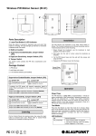
Wireless Remote Keypad (KP-S1) Parts Description 3. Fix the keypad base onto the wall with the screw and plugs provided. 1. Active LED (Blue/Orange) 4. Replace the keypad cover onto the base. 2. Status LED (Blue/Red) 3. Fault LED (Orange) 4. Away Arm Key 5. Home Arm Switch 6. Status Key Surface Fixing Knockouts x 2 7. Disarm Key 8. Panic Alarm Press both 1 and 3 key to trigger Panic alarm 9. Fire Alarm Press both 4 and 6 key to trigger Fire alarm 10. Emergency Alarm Press both 7 and 9 key to trigger Emergency alarm 11. Battery Insulator 12. Mounting Knockouts Operation 13. Tamper Switch The Tamper switch protects the PIR from unauthorized cover opening. Standby Mode 2 x wall plugs and screws The Remote Keypad features a power saving feature. When no key is pressed for 5 seconds, the Remote Keypad will turn off automatically to conserve power. When any key is pressed, the Remote Keypad will wake up and turn on Active LED to indicate it is now under normal operation 1 x 3V lithium batteries (pre-installed) Keypad Setting Package Content 1 x Remote Keypad Learning For learning the Remote Keypad: 1. Put the Control Panel into learning mode. 2. Press both # and keys to transmit learn code 3. Refer to Control Manual to complete the learning process. The Remote Keypad features a Test (programming) mode for you to customize its setting. Before you start using the Remote Keypad, you should first finish configuration setting. The Remote Keypad also feature a Keypad PIN code which is used to access the Test mode, To enter Test Mode, Enter “0000”(Default Keypad PIN code) + “*” key, the Active Orange LED will light up Under Test Mode, the following functions include: Key “*” + “7” “*” + “2” Function Transmit learn code (same as pressing both # and keys under normal mode) Enable dual key Panic Alarm function The Remote Keypad has 2 knockouts on the back where plastic “*” + “3” Enable dual key Fire Alarm function is thinner for wall mounting. “*” + “4” Enable dual key Medical Alarm function 1. Use the two knockouts on the back to mark position on the wall at chest height. “*” + “5” Disable all dual key functions “*” + “6” Change Keypad PIN Code: 1. Enter old code + “Status” Key 2. Enter new 4-digit code + “#” key Installation 2. Drill holes into the wall using the knockouts as template. “*” + “8” “*” + “9” “*” + “0” “Disarm” twice Enable Arming without Use PIN code function Enable Arm with User PIN code function (Default) Enable Arming with KP PIN code function To leave Test Mode Orange LED On Orange LED Off Alarm in memory Fault exists in system Battery The Remote Keypad uses one 3V lithium battery as its power source. It also features low battery detection function to notify the Control Panel when battery voltage is low. Arm/Home/Disarm When the Remote Keypad is on low battery, follow the procedure below to change the batteries. If Remote Keypad is set to “Arm with Use PIN code” (“*” + “9” under Test Mode) 1. Open the back cover. Away Arm Home Arm Disarm Enter a Control Panel User PIN Code + “Arm” Key Enter a Control Panel User PIN Code + “Home” Key Enter a Control Panel User PIN Code + “Disarm” Key If Remote Keypad is set to “Arm without Use PIN code” (“*” + “8” under Test Mode) Away Arm Home Arm Disarm Press “Arm” Key Press “Home” Key Enter a Control Panel User PIN Code + “Disarm” Key If Remote Keypad is set to “Arm with Keypad PIN code” (“*” + “0” under Test Mode) Away Arm Home Arm Disarm Press the Status key to inquire Control Panel status, the Status LED will light up according to Control Panel mode Away Arm mode Home Arm mode Disarm mode Dual Key Alarm Function Dual Key Alarm function will activate alarm when both keys are pressed at the same time. To use the functions, please enable them under Test Mode. (Default are disabled) “1” + “3” “4” + “6” “7” + “9” 3. Press any key several times to fully discharge. 4. Insert the new batteries observing correct polarity. 5. Replace the back cover. Factory Reset If you forget your Keypad PIN code, or the Remote Keypad has any problem, you can reset the Remote Keypad to factory default. 1. Open the back cover and remove the battery. 2. Press and hold “3” key and insert battery. 3. The Remote Keypad will sound 3 short beeps. 4. Release “3” key, the reset process is now complete. Enter Keypad PIN Code + “Arm” Key Enter Keypad PIN Code + “Home” Key Enter Keypad PIN Code + “Disarm” Key Checking Control Panel Status Red LED On Red LED Flash Blue LED on 2. Remove the old batteries. Panic Alarm Fire Alarm Emergency Alarm Specification Environmental Condition -10°C to 40°C, relative humidity 85% non-condensing. Radio 433 MHz FCC Statement This device complies with Part 15 of the FCC Rules. Operation is subject to the following two conditions: (1) This device may not cause harmful interference, and (2) This device must accept any interference received, including interference that may cause undesired operation. LED Indicators Active LED FCC Caution: The Active LED light up whenever any key is pressed. To assure continued compliance, any changes or modifications Off Blue LED On Blue LED Flash not expressly approved by the party responsible for compliance Keypad in Standby Mode Keypad in Normal Operation Keypad in Normal Operation and under Low Battery Orange LED On Keypad in Test Mode Orange LED Flash Keypad in Test Mode and under Low Battery Status LED The Status LED light up during operation or when the “Status” key is pressed to inquire Control Panel status Red LED On Red LED Flash Blue LED On Blue LED Flash Away Arm mode Home Arm mode Disarm mode No reply from Control Panel Incorrect PIN code Request for Home arm when under Away arm mode Request for Force Arm Fault LED The Fault LED light up whenever faults are detected in the alarm system. may void the user's authority to operate this equipment. (Example - use only shielded interface cables when connecting to computer or peripheral devices).