1
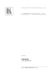
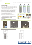
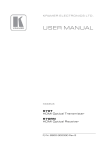
K R A ME R E LE CT R O N IC S L TD . PRELIMINARY USER MANUAL MODEL: PA-225NET Power Amplifier P/N: 2900-300408 Rev 1 Contents 1 Introduction 1 2 2.1 2.2 Getting Started Achieving the Best Performance Safety Instructions 2 2 3 3 Overview 4 4 Defining the PA-225NET Power Amplifier 5 5 5.1 5.2 5.3 5.4 Connecting the PA-225NET Connecting the PA-225NET Wiring the Inputs Connecting the Remote Controls Connecting Speakers 6 6 7 9 10 6 6.1 6.2 Operating the PA-225NET Indicators Setting the Priority Switch 11 11 11 7 Troubleshooting 12 8 Technical Specifications 13 Figures Figure 1: PA-225NET Power Amplifier Rear Panel Figure 2: Connecting the PA-225NET Power Amplifier Figure 3: Connecting a Balanced XLR Input Figure 4: Connecting a Balanced 6.5mm Phone Jack Figure 5: Connecting an unbalanced RCA Input Figure 6: Connecting an unbalanced 6.5mm Phone Jack Figure 7: Connecting the Remote Volume Control Figure 8: Connecting Galil 6-C Speakers to the PA-225NET 5 6 8 8 8 9 9 10 PA-225NET – Contents i 1 Introduction Welcome to Kramer Electronics! Since 1981, Kramer Electronics has been providing a world of unique, creative, and affordable solutions to the vast range of problems that confront the video, audio, presentation, and broadcasting professional on a daily basis. In recent years, we have redesigned and upgraded most of our line, making the best even better! Our 1,000-plus different models now appear in 14 groups that are clearly defined by function: GROUP 1: Distribution Amplifiers; GROUP 2: Switchers and Matrix Switchers; GROUP 3: Control Systems; GROUP 4: Format/Standards Converters; GROUP 5: Range Extenders and Repeaters; GROUP 6: Specialty AV Products; GROUP 7: Scan Converters and Scalers; GROUP 8: Cables and Connectors; GROUP 9: Room Connectivity; GROUP 10: Accessories and Rack Adapters and GROUP 11: Sierra Video Products; GROUP 12: Digital Signage; and GROUP 13: Audio, and GROUP 14: Collaboration. Congratulations on purchasing your Kramer PA-225NET Power Amplifier, which is ideal for the following typical applications: Dante™ network applications Presentation rooms and multimedia applications for local audio amplification Personal audio listening (for example, a PC and portable CD player) PA-225NET - Introduction 1 2 Getting Started We recommend that you: Unpack the equipment carefully and save the original box and packaging materials for possible future shipment Review the contents of this user manual Use Kramer high performance cables. Use only the power adapter that is supplied with this machine i 2.1 Go to http://www.kramerav.com/downloads/PA-225NET to check for up-todate user manuals, application programs, and to check if firmware upgrades are available (where appropriate). Achieving the Best Performance To achieve the best performance: Use only good quality connection cables (we recommend Kramer highperformance cables) to avoid interference, deterioration in signal quality due to poor matching, and elevated noise levels (often associated with low quality cables) Do not secure the cables in tight bundles or roll the slack into tight coils Avoid interference from neighboring electrical appliances that may adversely influence signal quality Position your Kramer PA-225NET away from moisture, excessive sunlight and dust ! 2 This equipment is to be used only inside a building. It may only be connected to other equipment that is installed inside a building. PA-225NET - Getting Started 2.2 Safety Instructions ! Caution: There are no operator serviceable parts inside the unit Warning: Use only the Kramer Electronics power supply that is provided with the unit Warning: Disconnect the power and unplug the unit from the wall before installing PA-225NET - Getting Started 3 3 Overview The Kramer PA-225NET is a high performance, networked power amplifier that accepts Dante a network and two balanced, mono audio inputs on 3-pin terminal blocks and converts the signal into a differential stereo audio output for speakers on a 4-pin terminal block. The PA-225NET Power Amplifier features: Dante and analog local inputs 2 x 25W into 8Ω 2 x 35W into 4Ω A balanced line-level output Independent volume control per input Priority switching between the Dante and local inputs The PA-225NET Power Amplifier is housed in a Kramer TOOLS enclosure. 4 PA-225NET - Overview 4 Defining the PA-225NET Power Amplifier Figure 1 defines the rear panel of the PA-225NET Power Amplifier. Figure 1: PA-225NET Power Amplifier Rear Panel # Feature Function 1 PRIORITY Switch 2 Dante RJ-45 Ethernet Connector 3 NET Priority is given to the Dante network signal, (see Section 6.2) LOCAL Priority is given to the Local input Connect to the Dante audio source via the LAN 2 Turn clockwise to increase the amplitude of the second input signal; turn anticlockwise to decrease the level 1 Turn clockwise to increase the amplitude of the first input signal; turn anticlockwise to decrease the level 4 LEVEL Trimmers 5 REMOTE 4-pin Terminal Block Connect to the remote, 10kΩ volume control, (for example, the W-LM) and mute-switch, (see Section 5.3) 6 ON LED Lights blue when the device receives power 7 SIGNAL LED Lights green when there is an input signal present 8 CLIP 1 LED Lights red when the signal clips on the first input signal 9 CLIP 2 LED Lights red when the signal clips on the second input signal 10 POWER 2-pin Terminal Block 11 12 13 2 LOCAL IN1 Input 2 LINE OUT 1 Output 14 15 SPEAKER Connect to the 48V power supply provided 3-pin Terminal Block Connect to a line-level, balanced, stereo audio source, (for example, a media player), see Section 5.2.1 3-pin Terminal Block Connect to a line-level, balanced, stereo audio source 3-pin Terminal Block Connect to an unbalanced, stereo audio acceptor, (for example, amplified speakers) 2 2-pin Terminal Block Connect to the output 2 4Ω or 8Ω speaker 1 2-pin Terminal Block Connect to the output 1 4Ω or 8Ω speaker PA-225NET - Defining the PA-225NET Power Amplifier 5 5 Connecting the PA-225NET This chapter comprises the following sections: 5.1 Connecting the PA-225NET (see Section 5.1) Wiring the inputs (see Section 5.2) Connecting the remote controls (see Section 5.3) Connecting the PA-225NET i Always switch off the power to each device before connecting it to your PA-225NET. After connecting your PA-225NET, connect its power and then switch on the power to each device. Figure 2: Connecting the PA-225NET Power Amplifier 6 PA-225NET - Connecting the PA-225NET To connect the PA-225NET as illustrated in the example in Figure 2: 1. Connect a balanced, stereo audio source, (for example, a multimedia player) to the 6-pin Local In terminal block, (see Section 5.2). 2. Connect a Dante network audio source to the Dante RJ-45 connector. 3. Set the Priority slide-switch to the required position, (see Section 6.2). 4. Connect the 3-pin Line Out 1 terminal block to the audio acceptor, (for example, a recording device). 5. Connect a remote volume control, (for example, the W-LM) to the Remote 4-pin terminal block, (pins +V, LEVEL, and GND). 6. Connect a remote, momentary mute-switch to the Remote 4-pin terminal block, (pins Mute and GND). 7. Connect the speakers to the Speaker 4-pin terminal block. 8. Connect the power adapter to the PA-225NET and plug the power adapter into the mains power supply. 5.2 Wiring the Inputs Your PA-225NET is provided with a 3-pin terminal block for its input connection. This connector can accept either a balanced or an unbalanced connection, however some modifications must be made for an unbalanced connection. 5.2.1 Wiring Balanced Inputs When using a balanced input source and connector, you must ensure that the hot, cold, and ground pins of the connector are matched up to the +, –, and ground pins of the PA-225NET terminal block connector respectively. The following diagrams illustrate how to connect standard XLR and TRS connectors. PA-225NET - Connecting the PA-225NET 7 Figure 3: Connecting a Balanced XLR Input Figure 4: Connecting a Balanced 6.5mm Phone Jack 5.2.2 Wiring Unbalanced Inputs When using an unbalanced input source, a jumper must be added between the negative (–) and ground terminals. The unbalanced source is connected to the positive (+) and ground terminals. Note: A jumper is required for connecting an unbalanced input. Figure 5: Connecting an unbalanced RCA Input 8 PA-225NET - Connecting the PA-225NET Figure 6: Connecting an unbalanced 6.5mm Phone Jack 5.3 Connecting the Remote Controls The following diagram illustrates how to connect the W-LM Remote Volume Control to the PA-225NET. Note: The remote volume control overrides the level control on the rear of the device. Figure 7: Connecting the Remote Volume Control PA-225NET - Connecting the PA-225NET 9 5.4 Connecting Speakers The following table details the cable requirements for connecting the PA-225NET to speakers. Distance m (ft) Wire Gauge (AWG) Up to 7 (25) 16 7.5 to 12 (26 to 40) 14 12 to 18 (41 to 60) 12 The speakers must be connected to the PA-225NET as shown in Figure 8. Figure 8: Connecting Galil 6-C Speakers to the PA-225NET 10 PA-225NET - Connecting the PA-225NET 6 6.1 Operating the PA-225NET Indicators The following table details the LED indicators. 6.2 Label Color Description SIGNAL Green There is an input signal present ON Blue The device is receiving power CLIP Red The input signal is being clipped Setting the Priority Switch The Priority switch determines which input takes priority in the event that there are two live input signals. When the switch is set to NET, priority is given to the Dante network signal; when the switch is set to Local, priority is given to the Local Input. In the absence of a signal on the priority input, the secondary input is automatically selected after about three seconds. PA-225NET - Operating the PA-225NET 11 7 Troubleshooting The PWR LED does not light. Check that the power adapter is plugged into a functioning outlet and that the adapter is correctly connected to the PA-225NET. No output is heard from the speakers; the CLIP LED lights. Check that the level control and remote volume control are not turned down. Check that the input and output connections are secure. Insure that the SIG LED lights to denote a signal. If there is no signal detected, check the signal source and that the level controls are set high enough. Amplifier overheats and/or shuts down. Check the CLIP LED on the rear of the amplifier to see if the signal is overdriving (the signal light flashes red frequently). Overdriving the amplifier for extended periods can cause a thermal shutdown. Output sound is distorted or cracking. Check all cables for damage or loose connections and reduce the gain on the input signal at the mixer or preamp level. Replace the cables and speakers temporarily to see if this resolves the problem. 12 PA-225NET - Troubleshooting 8 Technical Specifications INPUTS: 2 Balanced stereo +4dBu/10kΩ on a 6-pin removable terminal block OUTPUTS: 2 Line-level outputs on a 3-pin terminal block 2 Mono speaker outputs on a 4-pin removable terminal block INPUT SENSITIVITY: 0.5V (–3dBV) OUTPUT POWER: 2 x 35W @ 4Ω 2 x 25W @ 8Ω AMPLIFIER TYPE: Class D MAXIMUM VOLTAGE GAIN: 28X (26.5dB) INPUT IMPEDANCE: 20kΩ (balanced) 10kΩ (unbalanced) FREQUENCY RESPONSE (–3dB): 30Hz to 20kHz BANDWIDTH (-3dB): 30Hz to 30kHz S/N RATIO: >100dB AUDIO THD + NOISE: <0.1% SLEW RATE: 30V/ms CONTROLS: 2 Screw trimmers for line input sensitivity; remote 10kΩ volume control; contact-closure control for mute EXTERNAL MUTE: 5-12V DC LED INDICATORS: Power, Signal present, Clip 1, and Clip 2 POWER CONSUMPTION: Standby 3.3W; Idle current draw 6.9W; 1/8 current draw 14.2W DIMENSIONS: 15.6cm x 11.2cm x 6.8cm (6.14" x 4.41" x 2.68") W, D, H WEIGHT: 0.28 kg (0.62lbs) approx. SHIPPING WEIGHT: 0.9 kg (1.98lbs) approx. INCLUDED ACCESSORIES: Power adapter Specifications are subject to change without notice at http://www.kramerelectronics.com PA-225NET - Technical Specifications 13 For the latest information on our products and a list of Kramer distributors, visit our Web site where updates to this user manual may be found. We welcome your questions, comments, and feedback. Web site: www.kramerelectronics.com E-mail: [email protected] ! P/N: SAFETY WARNING Disconnect the unit from the power supply before opening and servicing 2900- 300408 Rev: 1