1
aee.com
Content
Conventions.....................................................................................................................................................................................2
Overview..........................................................................................................................................................................................2
1 Kit Contents............................................................................................................................................................................................................ 2
2 Quadcopter Introduction ....................................................................................................................................................................................... 3
Preparations before flight...............................................................................................................................................................4
1 Preparing Batteries.....................................................................................................................................................................4
1.1 Quadcopter Battery Introduction......................................................................................................................................................................... 4
1.3 Quadcopter Battery Installation........................................................................................................................................................................... 5
1.4 Caution................................................................................................................................................................................................................ 5
2 Preparing the Quadcopter..........................................................................................................................................................6
2.1 Introduction.......................................................................................................................................................................................................... 6
2.2 Flight Control System ......................................................................................................................................................................................... 6
2.3 Flight Indicator..................................................................................................................................................................................................... 6
2.4 Install the Camera Frame..................................................................................................................................................................................... 8
2.4.1 Install the Connector and Camera Cage:.......................................................................................................................................................... 8
2.4.1 Install the Connector and Camera Cage: ......................................................................................................................................................... 8
3 Preparing Propellers ..................................................................................................................................................................8
3.1 Introduction.......................................................................................................................................................................................................... 8
3.2 Assembling Propellers........................................................................................................................................................................................ 9
3.3 Disassembling Propellers.................................................................................................................................................................................... 9
3.4 Precautions ........................................................................................................................................................................................................ 9
4 Preparing the Remote control....................................................................................................................................................9
4.1 Introduction........................................................................................................................................................................................................ 10
4.2 Status Indicator on Remote control .................................................................................................................................................................. 10
4.3 Powering on the Remote control....................................................................................................................................................................... 11
4.4 Antenna Orientation........................................................................................................................................................................................... 11
4.5 Operating the Remote control........................................................................................................................................................................... 11
4.6 Frequency Pairing between Remote control and Receiver............................................................................................................................... 12
Flight...............................................................................................................................................................................................12
Flight Environment Requirements............................................................................................................................................................................ 12
Pre-flight Check:....................................................................................................................................................................................................... 13
1 Compass Calibration ...............................................................................................................................................................13
1.1 Calibration Procedures ..................................................................................................................................................................................... 13
1.2 When to Recalibrate.......................................................................................................................................................................................... 13
2 Starting / Stopping the Motor ..................................................................................................................................................13
2.1 Starting the motor ............................................................................................................................................................................................. 13
2.2 Stopping the Motors.......................................................................................................................................................................................... 14
3 Basic Flight ...............................................................................................................................................................................14
3.1 Basic Flight Procedures.................................................................................................................................................................................... 14
3.2 Aerial Photography Tips and Tricks (If camera installed already)..................................................................................................................... 14
4 Failsafe Protections ................................................................................................................................................................14
4.1 Scenarios when Quadcopter enters Failsafe mode.......................................................................................................................................... 14
4.2 Failsafe Procedure............................................................................................................................................................................................ 14
4.3 How to regain control during Failsafe Procedures............................................................................................................................................ 15
5 Low Battery Level Alarm Function.........................................................................................................................................15
Appendix........................................................................................................................................................................................15
1 Description of Common Indicators....................................................................................................................................................................... 15
2 Specifications....................................................................................................................................................................................................... 15
3 Common Troubleshooting.................................................................................................................................................................................... 16
Limited Warranty...........................................................................................................................................................................16
1
aee.com
AEE AP9 User Manual
V1.0 2015.4
Please read this " User Manual " carefully before using AP9.
Conventions
Except when specifically stated, all AP9 features described in this manual are for Quadcopter Operating Modes.
Warning:
(1) When installing the propellers, rotate the propellers strictly in the lock direction specified by the mark, and DO NOT apply too much force in order to avoid
possible damage.
(2) When removing the propellers, rotate the propellers strictly in the unlock direction specified by the mark, in order to avoid possible damage.
Overview
AP9 is a high-tech electronic product integrating flight control system. Thecamera can be mounted with a camera frame, which helps you easily capture clear and
stable aerial videos and photos.
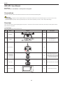
1 Kit Contents
Before using, please check all items inside the kit box.
No.
Name
Diagram
Quantity
1
Quadcopter
1 pcs
2
Propellers
2 pairs
3
Remote control
4
Q45 camera cage
(mounted on
the quadcopter
before delivery)
1 set
AEE S50/S51/S60/S71/S70/
OM51S/OM60S/OR60S/OR71S/
S40 and other series of cameras
can be mounted (Camera shall
be purchased separately)
5
camera cage
1 set
Gopro G3 cameras can be mounted
6
Quadcopter Battery
1 pcs
Quadcopter power supply
NULL
NRM
S2
S3
NULL
2 pcs with black nuts;
2 pcs with gray nuts
1 pcs
GPS
NULL
S1
Description
S4
2
aee.com
7
Quadcopter Battery
Charger
1 pcs
8
Tools
1 set
9
AA batteries
4 pcs
For Remote control power supply
10
Manuals
1 pcs
Including: AP9 User Manual , AP9
Quick Start Guide,Disclaimer
11
Propeller Guards
1 set
4 pcs Propeller Guards
12
CD
100-240V 50/60Hz
1pcs wrench - (for
disassembling propeller ) and
1pcs screwdriver (for assembling
propeller guard)
1 pcs
Possesses relevant AP9 information
(optional)
● Accessories you have received may vary due to different product customizations. Package contents are subject to change without further notice.
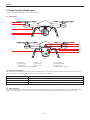
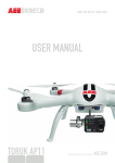
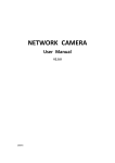
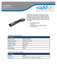
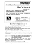
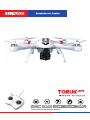
2 Quadcopter Introduction
Adopting compact integrated design, AP9 provides excellent flight control and aerial photography for outdoor low-altitude or large indoor spaces. You only need to
follow simple installation steps before flight and taking aerial photos. You can control the quadcopter in real-time fashion with the Remote control . Featuring simple
and flexible operating procedures, stable and reliable performance, AP9 is ideal for amateur or commercial photography.
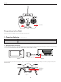
Remote control Device
Remote control with 2 joysticks, multichannel
Quadcopter External Components
Operating Modes
GPS mode
Power unit (motor &Propeller)
Normal mode
Quadcopter Internal
Components
Flight Control System
Receiver
ESC (Electronic Speed Control)
Quadcopter
Propellers
Motor
Camera Cage
Figure 1
3
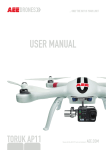
aee.com
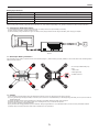
GPS
NULL
S1
NULL
NRM
S2
S3
NULL
S4
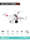
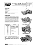
Transmitter
Figure2
Preparations before flight
Refer to the following for installing components and pre-flight quadcopter check.
1 Preparing Batteries
Ensure all device batteries are fully charged before operating AEE AP9.
Device
Power Supply
Remote control
Load 4 AA batteries for power supply.
Quadcopter
Charge quadcopter batteries for power supply.
The following instructions are for the quadcopter battery.
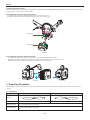
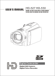
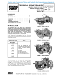
1.1 Quadcopter Battery Introduction
The quadcopter battery (Figure 3) is a specifically designed battery for AP9 with charge and discharge management functionality, with 5300mAh capacity and voltage
of 11.1V. Only use the dedicated quadcopter battery charger (Figure 4) provided by AEE, for charging.
Battery Charger Indicator
Figure3
Figure4
Short press the Battery Level Check button (Figure 5). Battery Level LCD Segment Display displays appropriate battery level. Please fully charge the battery if it is
less than two bars.
Battery Level
(Segment Display)
Battery Level
Check button
Figure 5
4
aee.com
Battery Specifications
Type
Li-Po Battery
Capacity
5300mAh
Charging ambient temperature
0°C-50°C
-20°C-50°C
Discharging ambient temperature
< 80%
Charge / discharge ambient relative humidity
Please carefully read and strictly comply with this manual before use. Users take full responsibility for any problems caused due to failure to follow instructions.
1.2 Charging the Quadcopter battery
(1) Connect the charger to an AC power source (100-240V, 50 / 60Hz). Please use a power adapter, if necessary.
(2) While charging, the battery charger indicator turns red.
(3) When the battery charger indicator turns green, the battery is fully charged. Disconnect the charger and battery when charging is complete.
Figure 6
1.3 Quadcopter Battery Installation
Push the battery into the battery compartment in the correct direction (Figure 7). After the battery is properly installed, a “click” sound will be heard, indicating that the
battery has been fastened.
An incorrectly installed battery may
cause
● Bad contact
● Affect flight safety
● Inability to take off.
Figure 7
1.4 Caution
(1) Do not directly pull out the battery when the Quadcopter is switched on as it may damage the power supply connector.
(2) For long term storage, discharge the battery to 40%-50% power, and store in a specified battery box. Discharge/charge the battery once every three months to
maintain battery life.
(3) Replace the battery after it has been discharged over 300 times. Completely discharge a battery prior to disposal.
(4) Replace the battery if your current battery swells up or is damaged in any way, to avoid fire and explosion.
(5) Do not charge expanded or damaged batteries.
(6) Pay attention while charging batteries to prevent accidents. Always charge batteries on a non-flammable surface, and never near any flammable materials.
(7) Battery safety is extremely important. Please refer to Disclaimer for more precautions.
5
aee.com
2 Preparing the Quadcopter
The quadcopter includes a built-in flight control system and motors etc.
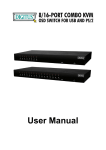
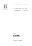
2.1 Introduction
[1]
[2]
[3]
[4]
[5]
[7]
[8]
[ 9 ]
[ 10 ]
[6]
[ 11 ]
Figure8
[ 1 ] Propellers
[ 2 ] Motor
[ 3 ] Front Indicator
[ 4 ] Camera Cage
[ 5 ] Landing Gear
[ 6 ] Quadcopter Battery
[ 7 ] Tail Indicator
[ 8 ] Power switch
[ 10 ] Battery Level LCD Segment Display
[ 9 ] Rear Indicator [ 11 ] Battery Level Check button
2.2 Flight Control System
AEE AP9 is equipped with AEE flight control system to provide incredible ease of use and stability. In addition to supporting basic flight maneuvers such as climb,
descend, roll and pitch, it also supports failsafe protection, battery level alarms and other functions.
System Component Modules
Function
Master Controller
Core module of the flight control system. Connects and controls all modules together.
GPS & Compass
Used for positioning and navigation.
Indicator
Indicates current flight control system status. Used to navigate during night flight.
2.3 Flight Indicator
There are three Flight Indicators, namely, the Front indicator, Rear indicator and Tail indicator. When the Quadcopter switch is turned on, the LED Flight Indicators
will be on. The Front indicator is green and the Rear indicator is red. (Hereafter use Green/Red Indicator to describe Front/Rear indicators respectively).
6
aee.com
Front Indicator
Tail Indicator
Rear Indicator
Figure9
AP9 LED Flight Indicators
MODE
Tail Indicator (green)
MODE
GPS normal
ON-Blinking-ON-Blinking
GPS failed
Blinking
Fast blink
WARNING & ERROR
Front Indicator (green)
WARNING & ERROR
1st Level low battery alarm
2 nd level low battery alarm
Remains ON
Rear Indicator (red)
Slow Blink(1s ON,1s OFF)
Slow Blink (1s ON,1s OFF)
Fast blink twice per second
Fast blink twice per second
Fast blink
Remains ON
Fast blink
Fast blink
Remains ON
Fast blink
Remains ON
blink twice at 3 second intervals
Compass abnormal
Accelerometer abnormal
Gyro abnormal
GPS Module abnormal
Barometer abnormal
Remains ON
blink once at 3 second intervals
COMPASS CALIBRATION INDICATOR
Front Indicator (green)
Rear Indicator (red)
Compass calibration entered
Fast blink
Remains ON
OFF
Remains ON
Remains ON
Remains ON
Compass calibration started
Compass calibration Successful
Compass calibration Failed
Fast blink
1second
1second
1second
Remains ON
1second
1second
1second
● In case a serious error occurs, the Tail LED Indicator continues blinking in red. When accelerometer, GPS, compass or other abnormal status occurs, please
refer to the solutions of Common Troubleshooting.
7
aee.com
2.4 Install the Camera Frame
Two types of camera frame can be mounted on AP9 quadcopter: 1. S50/S51/S60/S71/S70/OM51S/OM60S/OR60S/OR71S/S40 and other series of cameras can be
mounted in Q45. 2. G3 cameras can be mounted in Q44;
2.4.1 Install the Connector and Camera Cage:
(1) Install the cage seat onto the quadcopter and lock the screws, as shown in Fig. 10 (a).
(2) Install the camera frame onto the cage seat and lock the screws, as shown in Fig. 10 (b).
Figure10(a)
Figure10(b)
Figure10
2.4.1 Install the Connector and Camera Cage:
(1) Install the camera into the camera cage, as shown in Fig. 11 (a); reverse installation shall be avoided.
(2) Make sure the camera is installed in correct direction, and then lock the camera cage cover, as shown in Fig. 11 (b).
Note: The above figure is for Q45 camera cage; the same operation steps also apply to Q44.
+
=
Figure11(a)
Figure11(b)
3 Preparing Propellers
AEE AP9 adopts 10-inch propellers, with black and gray color propeller nuts. Propellers are consumable items. Please purchase these accessories separately, if
necessary.
3.1 Introduction
Propellers
Gray (1045)
Black (1045 P)
Diagram
Assembly Location
Attach to the motor shaft without "P" mark
Installation Location
Lockup: Tighten propeller in this direction
Symbol Description
Unlock: Loosen propeller in this direction
Attach to the motor shaft with "P" mark
8
aee.com
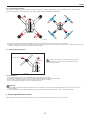
3.2 Assembling Propellers
(As shown below) Prepare two propellers with gray nuts and two with black nuts. Attach propellers with gray nuts to motor shafts without "P" marks, and attach
propellers with black nuts to motor shafts with "P" marks. Tighten propellers as per the appropriate locking direction.
Figure12
(1) Propellers are designed to self-tighten during flight; therefore do not tighten them excessively. Do not use glue on the threads.
(2) Ensure propellers are attached in the correct position. The quadcopter cannot fly properly if the propellers are installed incorrectly. Wear protective gloves while
installing as propellers are very thin and may cause accidental scratches.
3.3 Disassembling Propellers
Auxiliary wrench
As shown as in the Figure 13, prevent motor rotation by using
the auxiliary wrench or your hand, then remove propeller by turning
Unlock direction
towards the unlock direction.
3.4 Precautions
Figure13
(1) Check whether propellers and motors are installed correctly and firmly before every flight.
(2) Ensure that all propellers are in good condition before each flight. Replace aged, chipped or broken propellers.
(3) To avoid injury, stand clear of and do not touch propellers or motors when they are spinning.
(4) Only use original AEE propellers for a better and safer flight experience.
Warning :
(1) When installing the propellers, rotate the propellers strictly in the lock direction specified by the mark, and DO NOT apply too much force in order to avoid
possible damage.
(2) When removing the propellers, rotate the propellers strictly in the unlock direction specified by the mark, in order to avoid possible damage.
4 Preparing the Remote control
AEE AP9 Remote control is paired with the Quadcopter receiver before delivery. The Remote control is set to U.S. mode by default.
9
aee.com
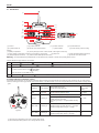
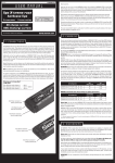
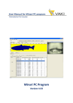
4.1 Introduction
[1]
[2]
[3]
[4]
GPS
NULL
S1
[6]
[7]
NULL
[5]
NRM
S2
S3
NULL
S4
[8]
[ 12 ]
[ 10 ]
[ 11 ]
[ 14 ]
[ 13 ]
[ 15 ]
[9]
[ 16 ]
Figure14
[ 1 ] Antenna
[ 2 ] 3-position Switch S1
[ 5 ] 3-position Switch S4 [ 6 ] Remote control Power Indicator
[ 3 ] 3-position Switch S2
[ 4 ] 3-position Switch S3
[ 7 ] Status indicator
[ 8 ] Photo shooting & video recording
indicator
[ 9 ] Battery Compartment
[ 10 ] Left Joystick ("Up & Down" controls Throttle, "Left & Right" controls Yaw)
[ 11 ] Right Joystick ("Left & Right” controls Roll, "Front & Back " controls Pitch)
[ 14 ] Strap Hole(Reserved function)
Warning :
[ 12 ] Strap Hole
[ 15 ] Airborne Shutter Button(Reserved function)
[13 ] Video Stop Button(Reserved function)
[ 16 ] Remote control Power Switch
To avoid accidental Injury, STAND CLEAR of and DO NOT touch propellers or motors when operating Remote control.
Function definition for toggle switch S1~S4 as below:
S1
3 positions, 1.
: Normal flight 2.
S2
3 positions, 1.
S3
3 positions, related control to servo
Reserved for future upgrading 3.
: Joystick calibration OK
2.
: (Reserved function) 3.
Reserved for future upgrading
: Calibrating Joystick
(Tilt up)
Stop(middle)
(Tilt down)
Note: This function is not available on AP9.
S4
3 positions, 1.GPS
: GPS mode
2. NRM
: Normal mode
3. NULL : null (reserved)
4.2 Status Indicator on Remote control
Upon startup of the quadcopter, you can judge the quadcopter status according to the status indicator on the Remote control. As shown in Fig. 15; there are three
indicators, including (from left to right): Remote control power indicator - red; status indicator - three color (red/green/blue);Photo shooting & video recording indicator
- green.
Remote Control Indicators
Designation
Power indicator
Status indicator (three-color)
Red light /Green light /Blue light
Photo shooting &
video recording
indicator
Functional
status
Red light●
Red light● /Green light●/Blue light●
Green light●
NRM mode: blue light (continuous)
GPS
NULL
S1
NULL
GPS mode: green light --> red light --> green light
(satellite searching successful)
GPS mode: green light --> red light (satellite searching
failed)
NRM
S2
S3
NULL
S4
Power on
Remaining on
ON --> OFF
NRM-->GPS
Remaining on
Satellite searching successful: blue light --> green light
Satellite searching failed: blue light --> red light
OFF
GPS-->NRM
Remaining on
Satellite searching successful: green light --> blue light
Satellite searching failed: red light --> blue light
OFF
Figure15
(1) When Remote control battery power is low, a warning alert sounds.
(2) When Quadcopter battery power is low, a warning alert also sounds.
10
aee.com
4.3 Powering on the Remote control
(1) Load four AA batteries into the battery compartment. Pay attention to positive and negative directions.
(2) Set S1 and S2 switches to the upper-most position and place both joysticks at the mid-point.
(3) Toggle power switch to ON position, to switch on the Remote control.
(4) The power indicator remains ON in red color after the Remote control is powered on.
● Ensure Remote control' batteries have sufficient charge before each use. If there is low voltage, the Remote control will prompt low power warning. Please
replace
batteries immediately.
● Be sure to remove batteries from Remote control in case of long-term storage.
● Remove depleted batteries and follow battery instructions for disposal or recycling.
Warning: Make sure not to touch the propellers when operating Remote control.
4.4 Antenna Orientation
Keep the Remote control antenna pointing skyward, and ensure there are no obstacles between Remote control and receiver antennas, to ensure maximum Remote
control range during flight.
Antenna
For maximum range and reliability, Remote control antenna should point
skyward with no obstructions between it and the receiver antenna on
Quadcopter. Obstructions may cause you to lose control of the quadcopter.
Ensure mobile device holder and Repeater do not block the antenna.
GPS
NULL
S1
NULL
NRM
S2
S3
NULL
S4
Figure16
4.5 Operating the Remote control
Joystick at center / neutral: Control joysticks of Remote control are at the central position.
Joystick deviation distance:The distance the Remote control joystick deviates from its center position.
Remote control (U.S. Mode)
Quadcopter Direction("
" indicates nose direction)
Operation Details
Vertical movements on the left joystick control
quadcopter elevation.
Push the left joystick up to ascend and down to
descend.
When both joysticks are centered (neutral), the
quadcopter will hover in place (height is automatically
set).
Push the left joystick upwards beyond the center
(neutral) position to take off. (Push the left joystick
slowly to prevent sudden and unexpected elevation).
Horizontal movements on the left joystick, controls the
rudder.
Push left to rotate quadcopter counterclockwise and
right for clockwise. If the joystick is centered, the
quadcopter flies in the same direction without rotating.
The joystick controls the quadcopter’s rotating
velocity. The more the joystick is moved the faster the
quadcopter will rotate.
11
aee.com
Vertical movements on the right joystick, controls the
quadcopter’s forward & backward pitch.
Push up to fly forward and down to fly backward.
The quadcopter will keep level and straight if the
joystick is centered.
Push the joystick further to increase pitch angle and
faster flight velocity.
Horizontal movements on the right joystick control left
and right pitch.
Push left to fly left and right to fly right.
The quadcopter will keep level and straight if the
joystick is centered
Push the joystick further to increase pitch angle and
faster flight velocity.
S2 switch is used to calibrate joysticks position.
Toggle S2 to Position-3 , then power on the
Remote control.
The photo capture status indicator (green) blinks. Then
move both joysticks clockwise and counterclockwise
twice, ensuring the joystick touches the maximum
S2
S2
Position-1
Position-2
positions.
S2
Position-3
After joystick calibration with the maximum stroke, the
status indicator in the middle will go out; finally, turn
S2 to position 1. The Video Indicator lights up (green),
and calibration is completed.
S4 switch is the flight mode toggle switch.
Position 1 (GPS) is GPS mode, Position 2 (NRM) is
S4
GPS
Position-1
S4
S4
NRM
Position-2
NULL
Normal mode, Position 3 (NULL) is Reserved function.
Position-3
● In GPS mode, when all joysticks are in the neutral position, the quadcopter hovers at a fixed-point.
● In Normal mode, when all joysticks are in the neutral position, the quadcopter remains level, but may drift in a horizontal direction.
● When S4 switch to GPS Mode, the motors can not be turned on until GPS is ready (Tail indicator remains on).
4.6 Frequency Pairing between Remote control and Receiver
The Remote control and receiver are paired before delivery. Normally, you can skip this procedure and directly use the quadcopter. However, if you change the
Remote control or Receiver, frequency-pairing is required.
Frequency Pairing Procedures
(1) Important:Be sure to remove propellers before pairing to avoid accidental injury.
(2) First, power off the remote control, then power on the quadcopter. The front/rear indicators and tail indicator light up. When you hear a "beep" sound, power on
the remote control, the power indicator lights up. When photo shooting & video recording indicator(green) lights up, the link between the remote control and
quadcopter is successfully eatablished.
(3) If photo shooting & video recording indicator(green) doesn‘t light up, do the second step again.
Flight
After installation, please conduct flight training (for example: Flight simulator training or professional training). Ensure that all flights are carried out in a suitable
environment.
Flight Environment Requirements
(1) Do not use the quadcopter in severe weather conditions, such as strong winds (category 4 and above), snow, rain and fog.
(2) Fly in an open area without tall buildings. Presence of large number of steel buildings in the area will affect the onboard compass.
(3) Keep AP9 away from obstacles, people, power lines, trees, shelters, surface of the water, etc., during flight.
(4) Reduce the chance of electromagnetic interference by not flying in areas with high levels of electromagnetism (such as near mobile phone base stations or
towers).
(5) This product cannot be used in The Antarctic Circle and The Arctic Circle.
(6) Do not fly the quadcopter within restricted or no-fly zones, and abide by local laws or regulations.
12
aee.com
Pre-flight Check:
(1) Ensure Remote control, Quadcopter are fully charged.
(2) Ensure propellers are correctly assembled.
(3) Ensure the Quadcopter, Remote control and other equipment are working properly after powering on.
(4) Check if motors start properly after the quadcopter is switched on. At this time, disassembling propellers is recommended for safety.
1 Compass Calibration
Compass calibration is required before first time use otherwise the system may not work properly, affecting flight safety. The compass is sensitive to electromagnetic
interference from other electronic devices, which can cause abnormal compass data leading to poor flight performance or even flight failure. Regular calibration is
required for optimum performance.
● Do not calibrate the compass in a strong magnetic field.
● Do not carry ferromagnetic material, such as keys, cell phones, etc., while calibrating the compass.
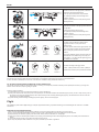
1.1 Calibration Procedures
Choose an open space to conduct calibration. Start the Remote control and quadcopter and ensure they work properly.
Follow the below procedures to calibrate the compass:
Rotate Quadcopter 360° horizontally
(2 turns)
Toggle the joysticks to the position as in
the follow figure.
Rotate Quadcopter vertically
(Nose leftward)
until green lights off
Rotate Quadcopter 360° vertically
2 turns (Nose down )
GPS
NULL
S1
NULL
NRM
S2
S3
NULL
S4
Top left joystick to top right corner
Top right joystick to top left corner
Start calibration
Put AP9 on the
ground
Front indicator (green)
starts blinking
Then release the joysticks
Green lights up
normally
after light off
Green lights
blink fast
after light off
Start horizontal calibration
Calibration success
Calibration failure
Recalibrate
Warning
Be sure to remove propellers before calibration, to avoid accidental injury or loss.
1.2 When to Recalibrate
(1) When compass data is abnormal, front indicator (green) blinks fast.
(2) The flight location is far from the place where last compass calibration was conducted.
(3) There are changes in quadcopter’s physical structure.
(4) The quadcopter drifts a lot while flying , such as it flies along a circle when hovering.
Warning
Be sure to remove propellers before calibrating to avoid accidental injury.
2 Starting / Stopping the Motor
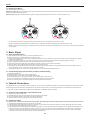
2.1 Starting the motor
Toggle the joysticks as shown in the illustration (Combination joystick Command [CSC]) to start the motor. Release the joysticks simultaneously after the motors
start, then the camera will start to record video automatically.
GPS
NULL
S1
NULL
NRM
S2
S3
NULL
S4
GPS
NRM
S1
S1:
S3
S2
S2:
S3:
NULL
S4
S4: GPS
When S4 switch to GPS Mode,
GPS
NRM
NULL
S4
the motors can not be turned on until GPS is ready .
Toggle Left joystick to left bottom corner.
Toggle Right joystick to right bottom corner.
Figure17
13
aee.com
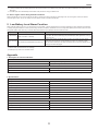
2.2 Stopping the Motors
There are two ways to stop the motors.
Method One (Figure 18): After the quadcopter lands, toggle the throttle joystick to the lowest position and then perform CSC, the motors will immediately stop.
Release both joysticks after the motors stop.
Method 2 (Figure 19): After the quadcopter lands, toggle the left joystick to the lowest position and hold for 3 seconds to stop the motor.
GPS
NULL
S1
NULL
GPS
NULL
NRM
S2
S3
NULL
S4
S1
NULL
NRM
S2
Figure 18
S3
NULL
S4
Figure 19
● Do not execute CSC during normal flight. This will stop the motors and cause the quadcopter to drop without control.
● Toggle the joysticks quickly and accurately when performing CSC. Release the joysticks simultaneously after the motors starts or stops.
● Shutdown Remote control must be after the quadcopter power off. Otherwise, the quadcopter will enter the return mode, then may case the high-speed rotation
of the propeller.
3 Basic Flight
3.1 Basic Flight Procedures
(1) Place AP9 on a flat and open ground, and ensure Tail Indicator faces you.
(2) Power on the Remote control and Quadcopter one after the other.
(3) Start the motors until the GPS signal is strong enough(the Tail indicator remains on) at GPS mode. Or, start the motors when the status indicator on Remote
control is blue at NRM mode.
(4) Push the left joystick up slowly for a smooth take-off. Please refer to Remote control operation instructions for detailed operation procedures.
(5) To land, gently pull down the left joystick to make the quadcopter descend slowly to the ground.
(6) After landing, pull the left joystick to the lowest position and hold for more than 3 seconds until the motors stop.
(7) After motors stop, power off Quadcopter and the Remote control one after the other.
● During flight if all 4 arm indicators slow blink or fast blink, it indicates the quadcopter has entered a low battery state. The Remote control will also make an
alarm sound, please refer to Low Battery Level Alarm Function for details.
● It takes approximately 40~60 seconds, when the GPS signal is strong enough after the quadcopter power on.
3.2 Aerial Photography Tips and Tricks (If camera installed already)
(1) Perform pre-flight checks.
(2) Capture photos and record videos during safe flight status.
(3) Capture photos and record videos in sunny weather with little wind.
(4) Set camera settings as per shooting requirements, such as video resolution, picture size, etc.
(5) Carry out a trial flight before actual flight to help plan the route and frame your photos and videos.
(6) Push the joystick as slowly as possible during flight to ensure the quadcopter flies smoothly.
4 Failsafe Protections
If the Quadcopter loses connection with the Remote control (i.e., you lose control), the Failsafe mode kicks in and the Automatic Flight Control system will control the
Quadcopter, fly it back to the Home Point and land it safely. This reduces chances of losing or crashing the Quadcopter in case the Remote control signal is lost.
● Home Point: Indicates the Quadcopter's position when the Quadcopter successfully scans the GPS signal.
4.1 Scenarios when Quadcopter enters Failsafe mode
(1) When Remote control is powered off.
(2) The Quadcopter has flown beyond the effective range of the Remote control signal.
(3) There are obstructions between the Remote control and the Quadcopter.
(4) There is interference causing a signal problem with the Remote control.
4.2 Failsafe Procedure
In case you lose control of the Quadcopter during flight, the Quadcopter will automatically follow the below operating procedures:
(1) The Quadcopter automatically slows down and hovers in one location.
(2) If the Quadcopter regains signal from the Remote control within 2 seconds, flight control returns to Normal mode, and the Quadcopter will not enter Failsafe
mode and will not automatically fly back to the Home Point.
(3) If the Quadcopter does not regain signal from the Remote control within 2 seconds, the Quadcopter enters Failsafe mode, and initiates automatic flight control
to fly back to the Home Point. The Quadcopter will now continue to hover for 15 seconds and evaluate vertical Distance to the Home Point. If the Distance
is less than 25 meters, the Quadcopter will fly up vertically to 25 meters higher than the Home Point, and then commence to return. When the Quadcopter
reaches the Home Point it will hover for 5 seconds and then automatically land.
14
aee.com
● To ensure the Quadcopter successfully flies back to the Home Point when it is in Failsafe mode, please take-off only after the Quadcopter successfully scans the
GPS signal.
● The Quadcopter cannot automatically avoid obstacles in its path when it is flying in Failsafe mode.
4.3 How to regain control during Failsafe Procedures
When the Quadcopter is out of control, toggle the S4 switch on the Remote control several times to switch flight mode. Once the signal is restored, the Remote
control will regain control, and you can continue to use the Remote control to operate the Quadcopter.
5 Low Battery Level Alarm Function
When quadcopter battery power is low, you must land as soon as possible, or else the quadcopter may lose power completely and crash, damaging the quadcopter
or creating a dangerous situation. In order to prevent danger caused by low battery, AP9 defines Level 1 low voltage alarm (battery level under 50%) and Level 2 low
voltage alarm (battery level under 20%), and sends alarms with indicators on the quadcopter and on the Remote control .
Battery Alarm
Low Power alarm
Severe Low Power
alarm
Flight indicator light status
4 arm indicators Slow Blink
(blinks on and off in 1s intervals)
4 arm indicators Fast Blink (blinks twice within 1s)
Low Power risk prompt
In level 1 alarm condition, Quadcopter flies normally for few minutes and then initiates
Level 2 alarm. Be cautious while flying, keep the Quadcopter within sight and do not to fly
too high or too far.
In level 2 alarm condition, Quadcopter flies normally for few minutes and then initiates
Failsafe mode and commences to automatically land. Under such a situation, please
return and land the Quadcopter as safely as possible, and do not push the throttle hard or
make big movements during flight.
During low-Power automatic landing, you can regain control of the Quadcopter by switching the flight mode. However, do not do so repeatedly, as it may:
1) Reduce battery service life due to over discharge.
2) Quadcopter may crash due to insufficient Power.
Appendix
1 Description of Common Indicators
Normal State
Front and Rear Indicators are ON; Tail Indicator remains on.
The GPS signal is strong enough.
Front and Rear indicators Remains ON, Tail Indicator Slow Blinks
Searching for GPS signals
Warnings and Abnormal State
Front and Rear Indicators Slow Blinks
Low Power alarm (first-level low power alarm)
Front and Rear Indicators Fast Blink
Severe Low Power alarm (second-level low power alarm)
Above indicator descriptions refer to common LED indicator states. For specific details, please refer to “Prepare the Quadcopter” in section 2.3 Flight Indicators.
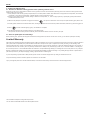
2 Specifications
Quadcopter
Battery
5300mAh LiPo
Weight
1.35kg / 2.98lbs
Hovering Accuracy
Horizontal: ±2.5m / 8.2ft , Vertical: ±0.8m/2.62ft
Maximum Tilt Angle
30°
Maximum Climb / Descent Speed
Climb: 6 m/s (19.69ft/s); Descend: 4 m/s (13.12ft/s)
Maximum Flight Speed
20m/s(65.62ft/s)(Not recommended)
Diagonal Length
450mm / 1.48ft
Flight Time
20min
Remote control
Data Transfer Distance
>700m (2296ft)
Working Hours
8h
Operating Current / Voltage
150mA / 6V
Battery
4 AA Batteries
15
aee.com
3 Common Troubleshooting
3.1 Solution for Remote control joysticks center (neutral) position errors
When there is a big error in neutral position of Remote control joysticks, the motors cannot start when performing CSC. Errors in Remote control joysticks neutral
position usually occur in two cases:
1. When quadcopter is ON and the joystick (except throttle) is not in neutral position-Solution: Move all Remote control joysticks to neutral position, and re-start the
quadcopter, to re-record the neutral position. If problem persists, it may be caused due to case.
2. Remote control joysticks have been trimmed, leading to deviation in neutral position, i.e., there is a large asymmetry in quadcopter joystick position-Solution:
Recalibrate the Remote control .
a) Make sure the quadcopter is powered off. Toggle S2 to Position-3
, then power on the Remote control. The photo capture indicator (green) blinks. Then
S2:
move both joysticks clockwise and counterclockwise twice, ensuring the joystick touches the maximum positions. Afterwards, release the joystick and toggle S2 to
Position-1
, the Video Indicator lights up (green), and calibration is completed.
S2:OK
(b) Re-start the quadcopter, and pay attention whether or not it starts properly.
If the problem cannot be solved by the above methods, please send back the Remote control to our factory for repair.
3.2 How can quadcopter land smoothly?
Before performing CSC, pull down the left joystick to less than5% ofthe joystick level, and then execute CSC. This way you can land the quadcopter smoothly.
Limited Warranty
AEE products are guaranteed against manufacturing defects, AEE's sole obligation in the event of such defects during this period is to repair or replace the defective
part or product with a comparable part or product at AEE's sole discretion. Except for such repair or replacement, the sale, processing or other handling of this
product is without warranty, condition or other liability even though the defect or loss is caused by negligence or other fault. Damage resulting from use, accident, or
normal wear and tear is not covered by this or any warranty. AEE assumes no liability for any accident, injury, death, loss, or other claim related to or resulting from
the use of this product. In no event shall AEE be liable for incidental or consequential damages relating to or resulting from the use of this product or any of its parts.
Because of possible user resealing error, this product is not warranted against leakage in waterproof housing or any resulting damage. Returns or replacements of
parts and/or products may be subject to shipping, handling, replacement and/or restocking fees.
If you are experiencing a problem with an AEE purchase, please contact our Customer Support Team by visiting our website www.aee.com .
For product warranty period and conditions, please refer to www.aee.com for details.
Tip: If you bought this product from an AEE authorized dealer, we would recommend that you first contact them for technical support issues
This User Manual is subject to change without prior notice.
You can check the official AEE website for the latest updated version.
16
AEE China HQ | Tel:+86-755-29518989 | E-mail:[email protected]
www.aee.com