1
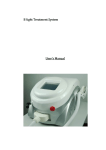
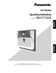
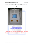
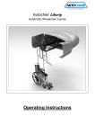
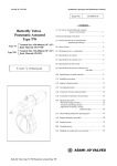
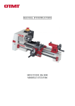
IPL Treatment System
User's Manual
WeiFang Huamei Electronics Co., Ltd.
0
Content
Chapter 1 System elucidation ............................................................................................................ 2
1.1 Specifications.................................................................................................................................... 2
1.2 Parts and control ............................................................................................................................... 2
1.3 Machine box.................................................................................................................................. 3
1.4 Control panel................................................................................................................................. 3
1.5 The IPL treatment head ................................................................................................................. 3
1.6 System program ................................................................................................................................ 4
1.7 The environment requirements ......................................................................................................... 4
Chapter 2 Installation and Debugging ............................................................................................ 5
2.1 Equipments detailed list.................................................................................................................... 5
2.2 Installation requirements................................................................................................................... 5
2.2.1 Space request ............................................................................................................................. 5
2.2.2 Electrical requirements .............................................................................................................. 5
2.2.3 Environment requirements......................................................................................................... 6
2.3 Installation ........................................................................................................................................ 6
2.4 Replace the water.............................................................................................................................. 8
2.5 Installing the filter............................................................................................................................. 9
Chapter 3 Operation .............................................................................................................................11
3.1 Software operation explanation .......................................................................................................11
3.1 Software instruction .........................................................................................................................11
3.2 Treatment ........................................................................................................................................ 15
Chapter 4 Accessory ............................................................................................................................ 16
4.1 Protective glasses ............................................................................................................................ 17
4.2 The Gel ........................................................................................................................................... 17
4.3 Order the accessory......................................................................................................................... 17
1
Chapter 1 System elucidation
This chapter introduces main parts of IPL: the control system and parameters.
1.1 Specifications
Model:
HM-IPL-B2
Spectrum range:
420-1200nm; 510-1200nm; 560-1200nm; 640-1200nm
Option:
585-1200nm; 690-1200nm, 755-1200nm
Energy density:
10-50J/cm2
Pulse sequence:
1.2, 3, 4, 5 pulse adjustable
Pulse intermission: 5-60ms
Pulse width:
2-15ms
Repeat frequency: 0.3-1Hz
Delivery:
Sapphire Coupling
Light spot:
8×40mm2 Option: 15×50mm2
Cooling system:
Water cooling, forced-air cooling and semiconductor cooling
Cooling temperature: -4 - 0℃
Power supply:
220V / 50Hz or 110v / 60Hz
Net Weight:
31kgs;
Size:
490mm×320mm×600mm
Gross Weight:
42kgs
Size:
570mm×380mm×680mm
1.2 Parts and control
Host
Control
panel
The IPL
head
treatment
The IPL treatment system is mainly made up of the following parts:
2
Host
Control panel
The IPL treatment head
This machine holds the micro-processor which can continually to supervise and control the
working of the system.
1.3 Machine box
Machine box is the heart of IPL system. It includes the following parts:
Power supply module: Supply power to other module and cut off power when the system has
malfunction;
The control module: Control and assort with the whole module of system;
The display controller: Display various information of the system, and accept the instruction of
users;
High voltage power supply: Supply electricity to capacitance;
Capacitance: Store energy that intense pulse light needs;
The Simmer power: light the lamp, and keep it in simmering state.
Cooling system: Cool the IPL treatment head.
Caution
Only the authorized engineer of the HUAMEI company can open the back cover board, and maintain
each internal module of this machine.
1.4 Control panel
The operator controls the system through the control panel which includes the following parts:
Key switch: To be used to turn on and off the power supply;
Emergency Switch: pressing this switch will shut off the whole power supply of system
immediately. It has priority over the system performance compared with the key switch. Follow the
arrowhead direction, turn the emergency switch clockwise and immediately loosen it, otherwise
the machine will be kept on shut off;
The LCD: The operator exchanges information by the LCD.
The system state, operation interface, hints and instructions are all on the LCD.
1.5 The IPL treatment head
The IPL treatment head contains electronics components emitting intense pulse. It connects
the system through a set of cable; there is a filter with filmed at the end of treatment head.
Pressing the red key on the IPL treatment head can emit intense light, which is delivered to
the area to be treated through the 8×40 mm² filter in the head. It is very important to keep the
filter clean.
3
Inside the IPL treatment head, there is the thermoelectricity type semi-conductor refrigeration
system used to cool down the filter. Then the temperature of the skin surface can be lowered down
so as to reduce the patient’s discomfort.
1.6 System program
The program of the IPL mainly has four functions:
Allow the doctor to choose the best characteristic parameters for the patients according to the
concrete diagnosis.
Control the working process of the system, in order to prevent unexpected trouble;
Examine the system energy;
Choose the treatment ranges;
1.7 The environment requirements
Working temperature scope:10℃~30℃;
Relative humidity scope:≤80%
Atmospheric pressure barometric:86kpa~106kpa;
The store environment temperature:0℃~55℃
Power supply:AC220V±22V/AC110V±11V, 50Hz/60Hz±1 Hz
4
Chapter 2 Installation and Debugging
The IPL treatment system can be used in the hospitals and the beauty salon. Before
installation, the preparation is very simple.
The installation process includes:
Dismantle the packing and place the IPL system in the pre-chosen location.
Check if the whole of system and parts.
Infuse distilled water into the water tank.
Connect the power supply.
Test all functions of the IPL.
Install and use
2.1 Equipments detailed list
The following is the detailed list of equipments of this machine:
Host
The IPL treatment head
Protective glasses
Gel
The plastics cover of filters
Funnel
Pipe
Power wire
Manual
DVD
2.2 Installation requirements
Before tearing down the packing of the IPL system, should check whether the
position conform to the requirements of this chapter.
2.2.1 Space request
The IPL system should be kept away from the hot place with a draught, and should be
kept a distance over 60 cm from other objects. It’s good for avoiding radiation and
collision.
2.2.2 Electrical requirements
Before the IPL leaves the factory, it has already been marked the local rated voltage
according to the customers’ request. It corresponds to the electricity requirement as
follows:
5
AC220V±10 %,10A,50Hz. or AC110V±10 %,16A, 60Hz
Input electric current can’t have momentary change, electric voltage or electric
current peak、sink.
The HUAMEI Company strongly suggests that the IPL system use separate wire and
air switches.
The main safty device in the machine is the 10 A chopper.
Caution
Please confirm the voltage (AC220V or AC110V) that you use agrees with the rated voltage
of IPL system.
2.2.3 Environment requirements
Air quality:No caustic particle (such as acid) in the air, which can damage the electric
wire, the electric component and optical component surfaces. The dust in the air should
be as little as possible, or it can absorb the energy of light and be heated up. When the
dust falls on the surface of the filter, it may damage the filter. Metal particles also could
damage the electric component.
Temperature:In order to guarantee the IPL system in the best working state, the
indoor temperature should be kept at 20℃~25℃, relative humidity should be less than
80%.The working power of this machine is about 2 KW, therefore, it is better for the
treatment room to have air-condition installed.
2.3 Installation
Take out the machine from the box and place it carefully in the appointed room, where
the indoor temperature is at 10℃~28℃, and the humidity is not over 80%. Keep the
operation room and treatment bed clean all the time.
Screw off the water
infusion plug. (Notice: use
infusion plug with hole during operation, use infusion plug without hole during
transportation)
6
Infuse distilled water from the water infusion hole until the water line reaches the 2/3
place of the water level observation window.
Install the treatment head. Requirement: keep the connection part dry and install it
correctly.
Link the power supply.
Switch on: After completing the above installation, insert the key and turn it left, the
machine is switched on at once, at this time, water begin to circulate, and the cooling
system starts automatically.
Check:Observe instrument to make sure that no water leaks. If it is leaks, shut off the
power supply, and contact the dealer.
Add water: When the water in the machine begins circulating, the water level inside
will drop, so you should add some water to the 2/3 place of water level observation.
7
2.4 Replace the water
Replace the water inside every 2 to 3 months and please do it according to the
following steps strictly:
Drain water in the machine: Screw off drain plug, lift up the front of the device to drain
water completely.
Infuse water again following the above-mentioned steps.
Link the power supply according to the above mentioned steps.
Attention:
1 In order to guarantee the safety of operation, please increase the distilled water up
to 2/3 place of the water level;
2. Please use the distilled water (not pure water) only.
3. if the machine has been in the room with its inside temperature below 0℃ for a
long time, there may be frost inside the machine and the machine may be damaged.
Method: place the machine in a room with a temperature at 20℃ for 24 hours, then you
can carry on operation.
Caution
1 In order to guarantee the machine operated safely, please increase the distilled
water to the cooling system in time. We are not responsible for the damage to the
treatment head because of the shortage of cooling water.
2、While adding the distilled water for the first time, please carry on according to the
above steps, then start the system;
3、Use the distilled water or purified water only. The water temperature can not be
lower than 5 degrees centigrade;
8
2.5 Installing the filter
If you choose the hand piece with interchangeable filters, Please install
the filter as following pictures, pay attention to the direction of the filter, i.e. the
direction of the arrow on the head should be in the direction of the arrow of the
filter.
9
Attain
Maybe it is caused by incomplete connection between the filter and
the head, if the cooling effect of the filter is not good。You can improve it
as the instructions of the following pictures: please loosen the screw on
the filter and press the filter gently and then screw on the filter tightly.
10
Chapter 3 Operation
This chapter describes the operation steps of the IPL system.
Warning
There is high voltage in the IPL, please make sure all front-panels are well covered;
When the IPL starts, please place the treatment head in its holder;
All personnel need to wear protection glasses or eye patch in the treatment room;
Even wearing the protective glasses do not look straight at the intense light emitted from
the treatment head.
The treatment head shall not point to any other place besides the target;
Excessive energy toward the area to be treated may hurt skin.
3.1 Software operation explanation
3.1 Software instruction
Switch on the machine and then the optional interface appears.
Select
mode
Language setting
Instruction :
Language setting to set the language of the system.)
Choose the treatment mode and enter the main menu, see the picture below:
11
treatment
Treatment parameter
storage area
The system hint area
Current Treatment mode
The total counter
The
output
energy value
The current counter
Reset the current
counter
The system state
The
output
energy meter
Parameter display
& adjustment
The key for start &
stop
The key for
energy output
adjustment
The key for pause
The cooling
meter
system
The key for cooling
system adjustment
The key for return
to the last interface
Instruction:
The system hint area to show the functions of the system.
displays that
the charge is finished and the system is ready for working;
displays the recharge trouble.
displays the water system is okay;
displays the water system in
trouble ( the system is in shortage of water or the water current is not circulating
smoothly.)。
displays that the Xenon lamp shines,
displays that the simmer fails。
displays the temperature of the system; it still shows the temperature of
20 ℃ when the temperature of it is below 20 ℃ ;
12
displays that the system
temperature is too high and the system has broken off.
Current Treatment mode displays the current treatment mode;
Treatment parameter storage area to be used to provide the saved treatment
parameters;
The output energy value displays the current energy value;
The system state displays the system state: the red shows that the system has not
been started or is in trouble; the yellow shows that the system is under preparation;
the green shows that the system is ready, in the meantime, if you step the foot
switch, the system will shine for treatment;
The output energy meter displays the energy value;
The key for energy output adjustment is to be used to increase or decrease the
energy;
The cooling system meter displays the cooling intensity of the system;
The key for cooling system adjustment
is to be used to increase or decrease the
cooling intensity of the system;
The total counter displays the total shots of the lamp;
The current counter displays the current shots of the lamp after switching on the
machine;
Reset the current counter is to be used to clear the current shots number of lamp
after switching on the machine;
Parameter display & adjustment displays the current treatment parameters; when
touching this area, the system enter the adjustment to the treatment parameters
interface;
The key for start & stop
to touch this key, the system try to light the lamp; touch
this key again and the lamp is switched off;
The key for pause when the lamp is ignited, if this key is touched, the system will
enter pause state; meantime, if you press the manual switch or the foot switch, the
treatment head will not flash,but the lamp is still on. During this time, you can adjust the
energy and cooling.
The key for return to the last interface
if you touch this key, the system will
return to the last interface;
Parameter display & adjustment: To show the treatment parameters of current
treatment mode.
Adjust the treatment parameters
13
Adjustable treatment parameters area
Pulse
Pulse cycle
Save & return
Save
the
parameter to
the
storage
area & return
The keyboard
Adjustable treatment parameters area is for the parameter adjustment area;
Pulse to be used to adjust the pulse number between 1 and 5;
Pulse cycle to be used to adjust the pulse cycle between 1s and 4s;
Save & return after adjusting the parameters, if you don’t want to save, please exit
from the interface;
Save the parameter to the storage area & return after adjusting the parameters, save
them in the Treatment parameter storage area and exit from the interface.
Firstly, please touch the Adjustable treatment parameters area, the digital get
underlined to show that this digital is adjustable; and then, touch the digital key board and
set the parameters; and last, touch the digital underlined again, the setting of the
parameter is finished.
First pulse width: When single pulse is used, the time it takes is regarded as the pulse
width , when multi-pulse is used, it’ width is the first pulse width. Adjust range (1-20ms),
when increasing a pulse; its pulse width should be increased by 0.1ms.
First pulse delay: The interval between the first pulse and assistant pulse (second
pulse), range (10-60ms), when increasing a pulse its pulse delay should be increased by
14
1ms.
Second-pulse width:Assistant pulse width won’t be shown when using single pulse,
range (1-20ms), when increasing a pulse its pulse delay should be increased by 0.1ms.
Second-pulse delay: The interval between the assistant pulse (second pulse) and
repeat pulse (third pulse and the late pulse) won’t be shown when using a single pulse,
range (10-60ms), when increasing a pulse its pulse delay should be increased by 1ms.
Repeat pulse width: Repeat pulse (the third pulse and late pulse) width won’t be
shown when using single pulse, range (1-20ms), when increasing a pulse its pulse delay
should be increased by 0.1ms.
Press “MENU” to enter treatment parameters interface. Press “△up ( for increase)
or ▽down (for decrease)”. Press “ENTER” will return to the treatment interface.
Pulse output:
First pulse (T1)
AssistantpulseT2
First delay
First pulse
Repeat pulse T3
Assistant delay
Repeat delay
Pulse interval
The interval is to avoid damaging skin by dividing light to several parts.
3.2 Treatment
1、Insert the plug of this machine, Insert the key and turn the key around to switch on
the machine. Almost immediately the “Introduction screen” is shown, it will automatically
switch to Picture 2. Then you can choose treatment mode and so on.
We suggest starting the treatment by using the lower energy density, emitting a test
light spot to evaluate the patient’s reaction.
2、After entering the working interface, the capacitance starts refresh. Press the
button on the head at this time, then can carry on the treatment. After a shot, the number
of counter will add one; the system starts recharged automatically, repeating the
above-mentioned process.
3、To check the cleanness of the filter. If it looks unclear, please wipe with wet soft
cloth.
4、spread gel of 2~3mm on the treatment area. The intense pulse light will be
conducted into the skin through gel which should be spread before treating.
15
5、Hold the treatment head vertically on the skin, press lightly, the treatment head
should get in touch with gel well.
6、 Press the button to shoot an intense pulse light, the system will refresh again
automatically, it takes about 2 seconds.
7、 Wipe off the gel, check the treated skin to evaluate patient’s instant reaction.
8、 Treat the next skin area, and allow 1mm between the next area and the treated
one.
9、Record the treatment parameters to provide information and reference for next
treatment.
Caution
We suggest the patient return the hospital to check after several weeks. In order to
confirm if treatment is needed to continue;
After the treatment, use soft cloth with alcohol to clean the treatment head gently.
Await orders:After pressing “SIMM”, The system enters waiting state, The intense
light lamp in the IPL treatment heads turned off, can't shoot the intense pulse light at this
time, After pressing the STR again, The system enters the working interface, The intense
light lamp in the treatment head was order bright, Can emit light at this time.
Counter:Record the shooting times after switch on each time
After the treatment, please put back head in the holder; let the system return the
“Menu screen", then switch it off by power key.
Danger
1、While entering the working interface, The IPL head must aim at the target skin,
then the trigger switch shall be activated.
2、When a stop is needed, press “SIMM” to switch to Await orders. This is in order to
avoid touching trigger switch by accident and injuring the patient's eyes.
3、No matter whether there is light output or not, the IPL head can not aim at anybody.
4、It’s not allow to aim at light at frangible such as eyes etc.
Chapter 4 Accessory
The accessories of this machine include:
·Protective glasses
·Eyepatch
16
·Gel
·Power cable
·Funnel
·Pipe
·User’s manual
·CD
4.1 Protective glasses
The protective glasses of the IPL can protect the eyes of the operatorsand patients.
4.2 The Gel
The gel is used to conduct the light and cool off the skin, there are six bottles per box,
250 grams per bottle.
4.3 Order the accessory
This machine has a complete set of accessories. If the customer needs more accessories,
please order them from the dealer.
17