1
GAS-FIRED COMMERCIAL
COPPER BOILERS FOR HYDRONIC
HEATING AND HOT WATER SUPPLY
User's Information Manual
GB/GW
MODELS:
1000, 1300, 1500, 1850, 2100, 2500
SERIES: 400, 401, 402, 403, 404, 405
LIGHTING INSTRUCTIONS
These models have an automatic hot surface ignition system
mounted on the combustion chamber panel inside the front jacket.
This hot surface igniter ignites the main burner gas whenever the
system control calls for heat.
WARNING: If the information in this
manual is not followed exactly, a fire or
explosion may result causing property
damage, personal injury or loss of life.
•
Before proceeding with operation of the unit, make sure the boiler
and system are filled with water and all air is expelled from the
boiler, radiator tank(s) and piping.
Do not store or use gasoline or
other flammable vapors and liquids
in the vicinity of this or any other
appliance.
WARNING
THE MAIN MANUAL GAS SHUT-OFF VALVE MUST HAVE
BEEN CLOSED FOR AT LEAST FIVE (5) MINUTES BEFORE
LIGHTING. THIS WAITING PERIOD IS AN IMPORTANT SAFETY
STEP. ITS PURPOSE IS TO PERMIT GAS THAT MIGHT HAVE
ACCUMULATED IN THE COMBUSTION CHAMBER TO CLEAR.
IF YOU DETECT GAS AT THE END OF THE PERIOD DO NOT
PROCEED WITH LIGHTING. RECOGNIZE THAT GAS ODOR,
EVEN IF IT SEEMS WEAK, MAY INDICATE PRESENCE OF
ACCUMULATED GAS SOME PLACE IN THE AREA WITH A
RISK OF FIRE OR EXPLOSION.
WHAT TO DO IF YOU SMELL GAS:
• Extinguish any open flame.
• Do not try to light any appliance.
• Do not touch any electrical switch;
do not use any phone in your
building.
• Immediately call your gas supplier
from a neighbor's phone. Follow the
gas supplier's instructions.
• If you cannot reach your gas
supplier, call the fire department.
•
WARNING
THERE IS A RISK IN USING FUEL BURNING APPLIANCES
SUCH AS GAS WATER BOILERS IN ROOMS, GARAGES OR
OTHER AREAS WHERE GASOLINE AND OTHER FLAMMABLE
LIQUIDS ARE USED OR STORED, OR ENGINE-DRIVEN
EQUIPMENT OR VEHICLES ARE STORED, OPERATED OR
REPAIRED. FLAMMABLE VAPORS ARE HEAVY AND TRAVEL
ALONG THE FLOOR AND MAY BE IGNITED BY THE BOILER'S
MAIN BURNER FLAMES CAUSING FIRE OR EXPLOSION.
Some local codes permit operation of gas appliances if installed
18 inches or more above the floor. This may reduce the risk if
location in such an area cannot be avoided.
Installation and service must be
performed by a qualified installer,
service agency or the gas supplier.
INDEX
PAGE
GENERAL ...................................................................... 1
LIGHTING INSTRUCTIONS .................................... 2 - 3
OPERATING SEQUENCE,
IGNITION CONTROLS INFORMATION ................. 4 - 18
TROUBLESHOOTING & MAINTENANCE ........... 19 - 23
WARRANTY ................................................................. 24
WARNING
SHOULD OVERHEATING OCCUR OR THE GAS SUPPLY FAIL
TO SHUT OFF, DO NOT TURN OFF OR DISCONNECT THE
ELECTRICAL SUPPLY TO THE PUMP. INSTEAD, SHUT OFF
THE GAS SUPPLY AT A LOCATION EXTERNAL TO THE
APPLIANCE.
WARNING
DO NOT USE THIS BOILER IF ANY PART HAS BEEN UNDER
WATER. IMMEDIATELY CALL A QUALIFIED SERVICE
TECHNICIAN TO INSPECT THE BOILER AND TO REPLACE
ANY PART OF THE CONTROL SYSTEM AND ANY GAS
CONTROL WHICH HAS BEEN UNDER WATER.
PRINTED IN U.S.A. 0906
MC BEE, SC RENTON, WA
STRATFORD-ONTARIO, VELDHOVEN-THE NETHERLANDS
www.hotwater.com
PLEASE KEEP THESE INSTRUCTIONS ADJACENT TO BOILER AND
NOTIFY OWNER TO KEEP FOR FUTURE REFERENCE
1
PART NO. 212512-000
Lighting Instructions for the G(B/W) 1000 through 2500 models
FOR YOUR SAFETY READ BEFORE OPERATING
WARNING: IF YOU DO NOT FOLLOW THESE INSTRUCTIONS EXACTLY, A FIRE
OR EXPLOSION MAY RESULT CAUSING PROPERTY DAMAGE, PERSONAL INJURY OR LOSS OF LIFE.
A. THIS APPLIANCE DOES NOT HAVE A PILOT. IT IS
EQUIPPED WITH AN IGNITION DEVICE WHICH
AUTOMATICALLY LIGHTS THE BURNER. DO NOT TRY
TO LIGHT THE BURNER BY HAND.
B. BEFORE OPERATING: SMELL ALL AROUND THE APPLIANCE AREA FOR GAS. BE SURE TO SMELL NEXT TO
THE FLOOR BECAUSE SOME GAS IS HEAVIER THAN
AIR AND WILL SETTLE ON THE FLOOR.
WHAT TO DO IF YOU SMELL GAS:
• DO NOT TRY TO LIGHT ANY APPLIANCE.
• DO NOT TOUCH ANY ELECTRIC SWITCH; DO NOT
USE ANY PHONE IN YOUR BUILDING.
• IMMEDIATELY CALL YOUR GAS SUPPLIER FROM A
NEIGHBOR’S PHONE. FOLLOW THE GAS SUPPLIER’S
INSTRUCTIONS.
• IF YOU CANNOT REACH YOUR GAS SUPPLIER, CALL
THE FIRE DEPARTMENT.
C. USE ONLY YOUR HAND TO PUSH IN OR TURN THE GAS
CONTROL KNOB. NEVER USE TOOLS. IF THE KNOB WILL
NOT PUSH IN OR TURN BY HAND, DON’T TRY TO REPAIR IT. CALL A QUALIFIED SERVICE TECHNICIAN.
FORCE OR ATTEMPTED REPAIR MAY RESULT IN A FIRE
OR EXPLOSION.
D. DO NOT USE THIS APPLIANCE IF ANY PART HAS BEEN
UNDER WATER. IMMEDIATELY CALL A QUALIFIED
SERVICE TECHNICIAN TO INSPECT THE APPLIANCE AND
TO REPLACE ANY PART OF THE CONTROL SYSTEM AND
ANY GAS CONTROL WHICH HAS BEEN UNDER WATER.
E. DO NOT OPERATE APPLIANCE UNLESS UNIT IS FILLED
WITH WATER AND WATER LINES ARE FULLY OPEN.
Note: Knob cannot be turned to "OFF" unless
knob is pushed in slightly. Do NOT force.
OPERATING INSTRUCTIONS
1.
2.
3.
4.
5.
6.
7.
STOP! READ THE SAFETY INFORMATION THE
NEXT STEP ABOVE ON THIS LABEL.
SET THE SYSTEM CONTROLLER TO THE LOWEST
SETTING.
TURN OFF ALL ELECTRIC POWER TO APPLIANCE.
THIS APPLIANCE IS EQUIPPED WITH AN IGNITION
DEVICE WHICH AUTOMATICALLY LIGHTS THE
BURNER. DO NOT TRY TO LIGHT THE BURNER BY
HAND.
REMOVE CONTROL ACCESS PANEL.
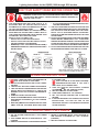
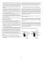
REFER TO DIAGRAMS ABOVE. TURN TOP KNOB OF
TO “OFF” POSITION,
GAS CONTROL CLOCKWISE
(FIGURE A).
WAIT FIVE (5) MINUTES TO CLEAR OUT ANY GAS. THEN
SMELL FOR GAS, INCLUDING NEAR THE FLOOR.
8.
9.
10.
11.
12.
IF YOU SMELL GAS,
STOP ! FOLLOW “B” IN THE SAFETY INFORMATION ABOVE ON THIS LABEL. IF YOU DON’T
SMELL GAS, GO TO THE NEXT STEP.
TURN TOP KNOB OF GAS CONTROL COUNTER
TO “ON” POSITION, (FIG. B).
CLOCKWISE
REPLACE CONTROL ACCESS PANEL.
TURN POWER SWITCH TO “ON” POSITION.
SET THE SYSTEM CONTROLLER TO DESIRED
SETTING.
IF THE APPLIANCE WILL NOT OPERATE, FOLLOW THE
INSTRUCTIONS “TO TURN OFF GAS TO THE
APPLIANCE” AND CALL YOUR SERVICE TECHNICIAN
OR GAS SUPPLIER.
TO TURN OFF GAS TO APPLIANCE
1. SET THE SYSTEM CONTROLLER TO THE LOWEST
SETTING.
2. TURN POWER SWITCH ON APPLIANCE TO “OFF”
POSITION.
3. REMOVE ACCESS PANEL TO EXPOSE GAS CONTROL.
4. REFER TO DIAGRAMS ABOVE. TURN TOP KNOB OF
GAS CONTROL CLOCKWISE (TO “OFF” POSITION,
(FIGURE A).
5. REPLACE CONTROL ACCESS PANEL.
2
Lighting Instructions for the G(B/W) 1000 through 2500 models
FOR YOUR SAFETY READ BEFORE OPERATING
WARNING: IF YOU DO NOT FOLLOW THESE INSTRUCTIONS EXACTLY, A
FIRE OR EXPLOSION MAY RESULT CAUSING PROPERTY DAMAGE, PERSONAL INJURY OR LOSS OF LIFE.
A. THIS APPLIANCE DOES NOT HAVE A PILOT. IT IS
EQUIPPED WITH AN IGNITION DEVICE WHICH
AUTOMATICALLY LIGHTS THE BURNER. DO NOT TRY TO
LIGHT THE BURNER BY HAND.
• IF YOU CANNOT REACH YOUR GAS SUPPLIER, CALL THE
FIRE DEPARTMENT.
C. USE ONLY YOUR HAND TO TURN THE MAIN MANUAL GAS
VALVE HANDLE. NEVER USE TOOLS. IF THE HANDLE WILL
NOT TURN BY HAND, DON’T TRY TO REPAIR IT. CALL A
QUALIFIED SERVICE TECHNICIAN. FORCE OR ATTEMPTED
REPAIR MAY RESULT IN A FIRE OR EXPLOSION.
B. BEFORE OPERATING: SMELL ALL AROUND THE
APPLIANCE AREA FOR GAS. BE SURE TO SMELL NEXT
TO THE FLOOR BECAUSE SOME GAS IS HEAVIER THAN
AIR AND WILL SETTLE ON THE FLOOR.
D. DO NOT USE THIS APPLIANCE IF ANY PART HAS BEEN
UNDER WATER. IMMEDIATELY CALL A QUALIFIED
SERVICE TECHNICIAN TO INSPECT THE APPLIANCE AND
TO REPLACE ANY PART OF THE CONTROL SYSTEM AND
ANY GAS CONTROL WHICH HAS BEEN UNDER WATER.
WHAT TO DO IF YOU SMELL GAS:
• DO NOT TRY TO LIGHT ANY APPLIANCE.
• DO NOT TOUCH ANY ELECTRIC SWITCH.
• DO NOT USE ANY PHONE IN YOUR BUILDING.
• IMMEDIATELY CALL YOUR GAS SUPPLIER FROM A
NEIGHBOR’S PHONE. FOLLOW THE GAS SUPPLIER’S
INSTRUCTIONS.
E. DO NOT OPERATE APPLIANCE UNLESS UNIT IS FILLED
WITH WATER AND WATER LINES ARE FULLY OPEN.
OPERATING INSTRUCTIONS
1.
2.
3.
4.
5.
6.
STOP! READ THE SAFETY INFORMATION ABOVE
ON THIS LABEL.
SET THE SYSTEM CONTROLLER TO THE LOWEST
SETTING.
TURN POWER SWITCH ON APPLIANCE TO “OFF”
POSITION.
TURN MAIN MANUAL GAS VALVE TO “OFF” POSITION,
(FIGURE “B”). THE VALVE IS “OFF” WHEN THE HANDLE IS
PERPENDICULAR TO THE GAS FLOW DIRECTION.
THIS APPLIANCE IS EQUIPPED WITH AN IGNITION
DEVICE WHICH AUTOMATICALLY LIGHTS THE BURNER,
DO NOT TRY TO LIGHT THE BURNER BY HAND.
WAIT FIVE (5) MINUTES TO CLEAR OUT ANY GAS. THEN
7.
8.
9.
10.
SMELL FOR GAS, INCLUDING NEAR THE FLOOR. IF YOU
SMELL GAS,
STOP! FOLLOW “B” IN THE SAFETY INFORMATION ABOVE ON THIS LABEL. IF YOU DON’T SMELL
GAS, GO TO THE NEXT STEP.
TURN MAIN MANUAL GAS VALVE TO “ON” POSITION,
(FIGURE “A”), THE VALVE IS “ON” WHEN THE HANDLE
IS PARALLEL TO THE GAS FLOW DIRECTION.
TURN POWER SWITCH TO “ON” POSITION.
SET THE SYSTEM CONTROLLER TO DESIRED SETTING.
IF THE APPLIANCE WILL NOT OPERATE, FOLLOW THE
INSTRUCTIONS “TO TURN OFF GAS TO THE APPLIANCE” AND CALL YOUR SERVICE TECHNICIAN OR GAS
SUPPLIER.
TO TURN OFF GAS TO APPLIANCE
3. TURN MAIN MANUAL GAS VALVE TO “OFF” POSITION,
(FIGURE “B”). THE VALVEIS “OFF” WHEN THE HANDLE
IS PERPENDICULAR TO THE GAS FLOW DIRECTION.
1. SET THE SYSTEM CONTROLLER TO THE LOWEST
SETTING.
2. TURN POWER SWITCH ON APPLIANCE TO “OFF”
POSITION.
3
in the design are the normal operating sequences and safety features
associated with a gas ignition control system. The system
continuously performs various diagnostic tests to verify proper
appliance and control operation. Should an unsafe condition occur,
the control will shut down the burner and display a red fault light as
well as indicate the cause of the fault on the display. The operating
programs for the system are stored in permanent memory inside
the micros. User-selectable operating parameters and a history of
detected faults are stored in re-writable memory in the micros. A
loss of power does not affect either of the memories.
WARNING
THE UNIT SHOULD NOT BE INSTALLED ON A CARPETED
FLOOR. A FIRE HAZARD MAY RESULT. Instead, the boiler must
be installed on the A. O. Smith Combustible Floor Kit Base or
concrete blocks extending beyond the full width and depth of the
boiler by at least 3 inches (76.2 mm).
FLAMMABLE ITEMS, PRESSURIZED CONTAINERS OR ANY
OTHER POTENTIAL FIRE HAZARDOUS ARTICLES MUST
NEVER BE PLACED ON OR ADJACENT TO THE BOILER.
OPEN CONTAINERS OF FLAMMABLE MATERIAL SHOULD
NOT BE STORED OR USED IN THE SAME ROOM WITH THE
BOILER.
Inputs To CCB and FCB:
• Temperature Sensors:
Light the unit in accordance with the instructions on the lighting and
operating label attached to the boiler. These instructions are repeated
on the previous two pages.
• Temperature probes (CCB - outlet and either inlet or tank is
required): The CCB accepts analog temperature inputs from up
to three sensors (inlet, outlet and tank).
• ECO input (CCB - required):
The ECO (energy cut off) is a thermostat switch, which is located
inside the output probe. It is a normally closed switch that opens
when exposed to a temperature higher than the trip point.
ELECTRONIC HOT SURFACE
IGNITION CONTROL BOARD
The EMC5000 control system is a fully integrated, state of the art
electronic control system. It consists of sensors, output devices, a
power switch, a 24vac transformer, wiring, and the following printed
circuit boards:
• Thermostat input (CCB - optional):
This input is set up to work with an externally connected
thermostat that provides a contact closure. If this input is closed
and everything else is in the proper state, a "call for heat"
condition will be initiated. These leads should be shorted
together, when a thermostat is not being used. If it is desired
that the thermostat control the temperature of the boiler, the
operating setpoint of the system should be set higher than the
temperature that the thermostat is controlling to. This will allow
the thermostat to control the boiler. When the thermostat closes,
a call for heat will be generated until the thermostat determines
that the control temperature has been reached.
Central Control Board (CCB).
Flame Control Board (FCB).
User Interface Board (UIB).
See Figure 1A.
See Figure 1B.
This part of the User Interface
Module (UIM). See Figure 3.
Power Distribution Board (PDB). See Figure 1C.
Touch Sensor Board (TSB).
This is part of the User
Interface Module (UIM). See
Figure 3.
• Air Pressure Sensors (open condition indicates fault):
The CCB contains circuitry for both master control and flame control
for the first stage. The FCB contains circuitry for flame control on
up to three additional stages. Dip switches on the CCB and FCB
are used to configure the system. The UIB and TSB are included in
the User Interface Module (UIM) along with a 4-line by 20-character
LCD display. The PDB provides connection points for input power,
the water pump, and the transformer. It also distributes power to the
system and contains the system fuses.
• Blocked Flue (CCB - required)
• Normally closed switch that opens if the flue becomes blocked
during operation.
• Powered Vent (CCB - optional):
Normally open switch that closes when the powered vent is
operating properly. This input is enabled-disabled by a dipswitch
on the CCB.
Multi-stage control is accomplished by means of an internal
communication network and the FCB's. One FCB is required for
each stage beyond the initial first stage. The CCB also contains an
external communications system to allow for connection to a PC, a
modem, an EMS system, or something similar. Through this
connection multiple boilers can also be linked together.
• Blower Prover High (FCB - required on stages that have blowers):
Normally open switch that closes when the air pressures
produced by the high-speed blower is above the trip level.
• Gas Pressure Sensors (open condition indicates fault):
CAUTION
The internal communications cables should never be connected to
the external communications connectors and vice-versa.
• Low Gas (CCB - required):
Normally open switch that closes when the gas pressure rises
above the trip level. This input is enabled/disabled by a dipswitch
on the CCB.
There are several microcontrollers used on the board. Three on
the CCB, two on the FCB, and one on the UIB. These micros control
the temperature and ignition control functions for the boiler. Inherent
• Hi Gas (FCB - optional):
4
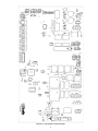
FIGURE 1A. CCB CENTRAL CONTROL BOARD
5
FIGURE 1B. FCB FLAME CONTROL BOARD
6
FIGURE 1C. PDB POWER DISTRIBUTION BOARD
7
power connections.) A red LED on the CCB is used to indicate
when the 24 vac input fuse has blown. The FCB's also have fuses
on their 24vac power line. (Recommended replacement fuses are:
Littlefuse p/n 29707.5 for the 7.5 amp CCB fuse, and Littlefuse p/
n 297003 for the 3 amp FCB fuses.) Repeated failure of fuse is
an indication of failure to some part of the system.
Normally closed switch that opens if the gas pressure exceeds a
set value. This input is enabled/disabled by a dipswitch on the CCB
and FCB's.
• Water Level Sensor (open conditions indicates fault):
• Low Water Cut Off (CCB - optional):
Normally closed switch opens if a low water condition occurs.
This input is enabled/disabled by a dipswitch on the CCB.
• Water Flow Switch:
• Flow (CCB - required):
Normally open switch that closes when flow reaches a set value.
• IRI Gas Valve Sensor:
• IRI Gas Valve (CCB - optional):
Normally open switch that closes when the IRI Gas Valve is
operating correctly. This input is enabled/disabled by a dipswitch
on the CCB.
• Flame Sensor:
• Flame (FCB - required on stage 1 and on stage 2 of a 4 stage
system - optional on others):
Returns a signal to the microprocessor if flame is detected on
the burner. If the probe is missing or shorted, the flame will not
be detected. This input is enabled/disabled by a dipswitch on
the FCB.
Yellow LED's are located near the micros on the CCB and FCB's.
These LED's are "heartbeat indicators" and blink approximately twice
per second to indicate that the micros are running. (The blink rate
of the LED next to the micro that controls the silicon nitrite igniter
will change when the igniter is being powered and when a fault is
detected with the operation of that igniter.)
CCB/FCB JUMPERS:
The CCB has two jumpers and the FCB has one. JP1 on the CCB
is used to terminate the external communications line. It is normally
left "OFF" and installed when the external cable is very long.
Igniters
Outputs from CCB and FCB's :
EMC-5000 system includes a Silicon Carbide igniter, Norton type
271Y (at 2.7 amps). The igniter is activated through relays on the
system boards and use a current sensing system for proof of ignition.
This circuit monitors the igniter operation and signal the CCB and
FCB micros when faults are detected. A yellow "heartbeat" LED
located next to the dedicated micro flashes a two digit code when
faults are detected.
• Relay Contact Outputs:
• IRI Gas Valve (CCB - 120vac- optional):
Provides electrical power to operate an IRI Gas Valve device.
• Alarm (CCB - 24vac- optional):
Provides electrical power to operate on external alarm. This can
be an audio device (i.e. Sonalert), a visual device (lamp), or any
other device that will operate with the voltage and current level
provided.
• Pump (CCB - 120vac - required on systems that do not have an
external pump):
Provides electrical power to directly operate a pump or the coil
of an externally connected contactor.
• Powered Vent (CCB - 24vac - optional):
Provides electrical power to operate a powered vent.
• Low and High Speed Blowers (FCB - 120vac - required on stage
1 and on stage 2 of a 4-stage system and optional on others.):
Independent outputs that provide power to operate low and high
blower output only. Dip switches on the FCB's enable/disable
the use of blowers on stages 2, 3 and 4.
• Igniter (FCB - 120vac - required on stage 1 and on stage 2 of a
4-stage system and optional on others.):
Provides power to operate the igniters. Dip switches on the FCB's
enables/disables the use of an igniter on stages 2, 3 and 4.
• Gas Valve (FCB - 24vac - required):
Provides power to activate the gas valve. The gas valve cannot
be activated when the ECO contacts are open.
• Direct Connection Output:
• Low Water Cut Off (CCB - 24vac - optional):
Directly connected to the 24 vac line to provide power to operate
an external LWCO device.
Appliance Operating Sequence
NOTE: The following sequence is based on a four-stage system
with all options and two-speed blowers. It is characteristic of most
system configurations.
1. The EMC5000 controller has four modes of operation:
Initialization, Standby, Running and Service. The internal CCB
and FCB micros control these modes through a sequence of steps
(or States) which are further described in the "UIM Operating
Procedures" section.
2. When power is applied to the system, it enters the Initialization
mode and the following automatic functions are performed:
•
•
•
•
•
•
Line Polarity Indicator & Fuse Protection
CCB/FCB Indicator Lamps & Fuses
•
•
•
A green LED is mounted on the PDB to indicate when line voltage
is applied. (The PDB also contains a yellow LED, a red LED, and
a test-run jumper, that are used during installation to verify proper
8
A. O. Smith opening screen is displayed.
The system goes through a self-calibration indicated by the green
running LED blinking and then staying on: next the red service
LED and yellow standby LEDS come on; next the stage 1 service
and running LEDS blink on and off followed by stage 2, stage 3,
stage 4 and then back to stage 1,2,3,4 LEDS.
Stored values are recalled from memory.
Configuration dipswitches are read.
Pending faults are recalled
Micros on all boards start running (indicated by a flashing Yellow
LED near each micro)
Input sensors are read
Communications between micros and boards is established
FCB's are configurated with the number of ignition trials
to run.
CCB/FCB Dip Switches:
Dipswitch configurations are READ ONLY ON POWER UP. These switches are only to be set at the factory or by authorized trained
personnel only! Once set at installation they generally remain that way for the duration of the life of the product. If a switch is
changed, power must be cycled before the change will take effect. The status of all dipswitches can be observed on the system
status screen on the UIM.CCB - Ten Position Dipswitch (Central Control Section):
Switch 1: Selection of the type of boiler application:
Switch 2: Trials for ignition:
Switch 3: IRI Gas Valve Option:
Switch 4: Controlling Probe:
Switch 5: Powered Vent:
Switch 6: Low Water Cut Off:
Switch 7: Low Gas
Switch 8: Spare:
Switch 9 & 10. Number stages (FCB's):
Boilers
Water Heaters
On = GB/LB
Off = GW/LW
On = 3
Off = 1
On = IRI
Off = No IRI
On = Tank (Remote) Off = Inlet
On = Yes
Off = No
On = Yes
Off = No
On = Yes
Off = No
9
Off
Off
On
On
10
Off
On
Off
On
#stages
= 1
= 2
= 3
= 4
NOTE: If the unit powers up with the number of stages selected by dip switches exceeding the number of FCBs, the CCB will detect
this condition and go into a hard lockout. After changing the dip switches to the correct number of stages, the power must be cycled
on and off to accept the change.
Example of Dip Switch configuration:
GW model, 1 ignition trial, IRI, Tank Probe used, No Power Vent, No LWCO,
No Low Gas, 3 stage.
CCB - Three position Dipswitch (Flame Control Section):
This dipswitch is similar to the FCB dipswitches described below, but with only three switches being used: the number of blower
speeds (switch #3), Hi Gas option (switch #2) and a spare (switch #1). Only the blower speed selection and Hi Gas are required
because FCB1 always has a blower, igniter, flame checking, and the address is always stage 1.
FCB - Eight position Dipswitch:
Switch 1: Spare:
Switch 2: Hi Gas:
Switch 3: Number of Blower Speeds:
Switch 4: Igniter used:
Switch 5*: Blower used:
Switch 6: Flame Checked:
Switch 7 & 8. Stage selection:
On
On
On
On
On
7
Off
On
Off
On
=
=
=
=
=
Yes
1 speed,
Yes,
Yes,
Yes,
8
Off
Off
On
On
Off = No
Off = 2 speed
Off = No
Off = No
Off = No
Stage #
Not allowed
2
3
4
*When switch 5 is in off (no blower) position, switch 3 (blower speeds) is ignored.
Example of Dip Switch configuration:
No High Gas, 1 blower speed, no igniter, no blower,
flame not checked, Stage 2.
9
NOTE: In standby and running modes the system constantly
monitors the signals and the internal operation for faults. Any
detected fault will halt the heating sequence and shift the system to
the service mode, where the detected fault will be displayed.
3. After initialization is complete (approximately 10 seconds) the
system turns the green LED off and goes to the standby mode
(yellow "Standby" LED on), unless a previously stored fault has
been recalled, which will send the system into the service model
(red "Service" LED on). In standby mode the display shows the
temperature screen and in fault mode the current error screen is
displayed.
4. The system then compares the temperature read from the
controlling probe (inlet or tank) to the setpoint temperature. If
the temperature is less than the operating setpoint minus the
differential temperature and the thermostat input is closed then
a call for heat is established and the system shifts to the run
mode (green "Running" LED turns on).
5. The heating sequence begins by applying power to the pump
and, if selected, the powered vent and the IRI gas valve.
6. After a few seconds the High Speed Blower (on all stages with
the blower dipswitch turned on) are turned on to perform a cold
purge of the chamber.
7. After cold purging is complete the blowers are turned off and the
stage 1 blower is turned on.
8. The stage 1 igniter is turned on.
9. After 18 seconds the system checks that the igniter has turned
on. If this is ok then the system turns on the gas valve.
10. After 1.5 seconds the system checks the status of the flame
sensor. If flame is detected the system proceeds to the next
stage. Note: If the "Ignition Tries" dipswitch is set for 3 tries the
system will not declare an error until it tries the ignition sequence
three times. If it is set to 1 try then the system will declare an
error anytime a fault is detected.
11. The system now activates the other FCB stages depending upon
a control algorithm scheme that is described below. For this
example it is assumed that all four stages of heat are required.
12. The stage 2 high-speed blower is turned on to purge the chamber.
13. After approximately 10 seconds the stage 2 igniter is turned on.
14. After 18 seconds the system checks that the igniter has turned
on. If this is ok then the system turns on the gas valve.
15.After 1.5 seconds the system checks the status of the flame
sensor. If flame is detected the system continues to the next
stage.
16. Steps 12 through 15 are then repeated for stage 3 and 4.
17. The system is now in the heating mode with all four stages on
and will remain in this mode until the call for heat is satisfied or
a fault occurs.
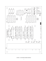
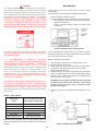
Temperature Setpoints (System Control Algorithm)
The boiler has a hysteresis type control, which means that it will
begin heating the water when the temperature sensed by the control
probe (inlet or tank) falls below the operating setpoint minus the
differential setpoint for stage 1. It will stop heating the water when
the temperature rises to the operating setpoint. If the system has
multiple stages then the differential setpoint for each stage is also
subtracted from the operating setpoint. The following examples will
further explain this operation.
Setup: 2 stage system, operating setpoint - 140, stage 1 to 2
differential setpoints = 10.
Example 1. Temperature begins at 150 and drops to 90, see Figure
2A. At 140 the system remains in idle mode. As the temp drops to
130 (140-10) stage 1 turns on and stage 2 remains off. At 120 stage
2 also turns on.
Example 2. Temperature begins at 90 and rises to 150, see Figure
2B. At 100 both stages are on. This is the case when a boiler is first
started and the controlling temperature is below the operating
setpoint minus all of the differential setpoints. At that time both
stages are turned on, in sequence from 1 to 2. At 130 stage 2 turns
off. At 140 both stages are off.
Stages 1 and 2 will turn on in sequence from 1 to 2.
FIGURE 2A.
10
FIGURE 2B.
The following status information is displayed from this screen:
Status Displayed
*(True Condition)
Input
Output
ECO
LWCO
Blk Flue
Flow
Low Gas
Tstat
Hi Limit
Pump
IRI Gas Pwr
IRI Gas
Pwr Vent
Alarm
Pwr Vent Pwr
Outlet temperature too high
Water Level low
Flue blocked
Water flowing
Gas pressure low
Thermostat requesting heat
Outlet temp exceeds High Limit setpoint
Pump output activated
IRI output relay activated
IRI Gas Valve on
Power Vent running
Alarm output activated
Power Vent output relay activated
- - - - STAGES 1 to 4 - - - Blower pressure sufficient
Blower High output activated
Blower pressure sufficient
Blower low output activated
Igniter current sufficient for ignition
Igniter output is activated
Gas output relay activated
Gas pressure too high
Flame detected
open
open
open
closed
open
closed
---------closed
closed
-------
---------------------On
On
------On
On
closed
---closed
------------open
----
---On
---On
---On
On
-------
BlwHi Prv
Blw Hi
BlwLo Prv
Blw Lo
Ignt Cur
Ignit
Gas Relay
Hi Gas
Flame
FIGURE 5. SYSTEM STATUS SCREEN.
UIM Operating Procedures
screens, up/down arrows appear on the right side of the screen to
indicate that there are additional lines either above or below the
displayed four lines.
• Menu Screen:
Displayed when the user presses the "Menu" key. This screen is
the selection point for the other 9 screens.
• Temperature Screen:
Displays the sensed temperatures of the Outlet, Inlet, and Tank
probes. Also displayed is the calculated Delta T (Outlet minus
Inlet) for the system. Shorted ("Short") and disconnected ("----")
probes are also displayed.
• System Status Screen:
This screen is used to view the status of switch inputs and output
states. An asterisk (*) is displayed next to the label when the
status is "True" (the description is fulfilled). For example, if water
is flowing, or detected by the flow sensor, then an "*" will appear
in front of the Flow label (i.e. *Flow). Another example would be
the ECO switch. If the outlet temperature is too high the display
will show: *ECO.
FIGURE 3. UIM.
The UIM receives commands from the user and displays
operational information to the user via an LCD (liquid crystal
display) up to eleven LED's, and five touch switches. The LCD
provides information to the user by the use of 10 menu-activated
screens. Within each of the screens, helpful information can be
displayed by pressing the "Help" button. The LED's visually inform
the user about the mode the system is in. The touch switches
allow the user to control the operation of the system. The operation
of these parts is described below:
NOTE: The LWCO, IRI Gas Valve, Powered Vent and High Gas
inputs are optional inputs. Flame sensing, Igniters, and Blowers
are optional on Stages 2, 3 and 4. (Except on a 4-stage system,
stage 2 always has an Igniter, Blower, and Flame Sensor. Those
dipswitches on stage 2 are not relevant.) One or two speed blowers
can be used on any stage.
The System monitors the inputs at these times:
UIM Screens:
On all screens a double vertical bar appears on the right side of
the display each time a key is touched to indicate that a key has
been activated. On several screens an indicator ">" appears on
the left side of the display to indicate the active line. The "Up/
Down" keys are used to move the indicator to the desired line and
the "Select" key is pressed to select the line. Also, on most of the
• ECO, LWCO, Blocked Flue, Low Gas, Hi Limit, and Hi Gas - at
all times for a fault condition.
• Tstat - at all times for open/closed conditions.
• Pump, IRI Gas and Powered Vent - for an on condition when
their respective outputs (Pump, IRI Gas Pwr, Powered Vent
Power) are turned on and an off condition at all other times.
11
• Flow - for an on condition when the pump is on (no check for off
state)
• High Speed Blower Prover - when the High Speed Blower is on.
• Low Speed Blower Prover - when either the High or Low Speed
Blowers are on.
• Igniter Current - for an on condition approximately 18 seconds
after the Igniter is turned on until the igniter is turned off and an
off condition at all other times.
• Flame - for an on condition approximately 5 seconds after the
gas valve is turned on until the valve is turned off and at all other
times for an off condition.
•
While the CCB is in the Heating mode the activated FCB stage
moves from Idle, to Pre-Purge, to Heat Igniter, to Check for Flame,
and then to Heating. The process waits in this state until the call
for heat is satisfied, the thermostat input is opened, or a fault
occurs. When heat is satisfied, the sequence continues to PostPurge and then back to Idle. If three tries for ignition has been
selected on the CCB dipswitch and flame is not detected at the
appropriate time, then the sequence moves to the Inter-Purge
state for 15 seconds and the FCB heat sequence is repeated. If
flame is still not detected after the third try the process declares
a fault, jumps out of sequence and goes to the error state. Other
types of faults detected at any time will also cause a jump to the
error state.
Control Status Screen:
Displays the software that the CCB and FCB micros are in. The
CCB has 8 possible states and the FCB's have 9. The normal
CCB states sequence is to move from Idle, to Pre-Circulate, then
to Heating Stage 1-4 when a call for heat is initiated. Once heat
has been satisfied, the sequence moves to Post-Circulate and
then back to Idle. If a fault occurs at any time, the process jumps
out of sequence and goes directly to the appropriate Hard or Soft
Fault state.
Description of CCB control states:
•
•
•
•
•
•
•
•
Hard Fault State: (See "Fault Description" section for list of
soft and Auto Reset faults.) The CCB turns off the Powered
Vent and the IRI Gas. The pump remains on for the selected
post-circulate time to cycle the hot water out of the boiler. The
FCB's are commanded to shut down and the Alarm output is
turned on. The green LED turns off and the red "Service" turns
on and off (flashes). The only way to exit this state is for the
user to press the Select key while the current error screen is
displayed. The fault is logged in the error history when the fault
state is exited.
Idle:
The yellow "Standby" LED is turned on and the system waits for
a heat request (determined by the Thermostat and controlling
probe inputs). All outputs are off in this state except that if the
Post-Circulate time is set to continuous the pump will be on.
When the heat request is received, the system moves to the
Pre-Circulate state.
Pre-Circulate:
The yellow LED is turned off and the green "Running" LED is
turned on. The green LED will remain on for all other states
except the fault states. If enabled the powered vent and the
IRI gas valve are turned on. A command is sent to all active
stages to cold purge the system. Cold purging clears out any
combustion gas that may be in the combustion chamber.
When purging is complete the system moves to the Heat State.
Heat Stages 1-4:
The system will command the FCB micros to start their heat
sequence starting with stage 1. Stages 2 through 4 will be
activated in order based on an algorithm that determines how
much heat is needed. The system will remain in this state until
the heat request is satisfied, the Tstat is opened, or a fault occurs.
Soft Fault State: (See "Fault Description" section for list of soft
and Auto Reset faults.)
The CCB turns off the Powered Vent and the IRI Gas. The pump
remains on for the selected post-circulate time to cycle the hot
water out of the boiler. The FCB's are commanded to shut down
and the Alarm output is turned on. The green LED turns off and
the red "Service" turns on. The CCB remains in this state until
one of the following occurs:
One hour passes (automatic restart after one hour)
If Communications error system will automatically restart if
communications are OK.
If user presses Select key while current error screen is displayed
(Hard reset).
If high-limit error - the outlet temperature drops below the high
limit trip point minus the high limit differential. (outlet water
temperature drops to safe level).
The fault is logged in the error history when the fault state is
exited.
Description of FCB control states:
•
•
•
•
12
Idle State:
If a Silicon Nitrite igniter is being used then its condition is
determined and any error is declared. The system will remain in
this state until the CCB requests a heating cycle or a cold purge.
The blowers, igniter, and gas relay are turned off.
Pre-Purge State:
If the stage does not have a blower, this state is skipped and
the system advances to the Heat Igniter State. Otherwise the
Hi-Speed Blower is turned on. After 10 to 34 seconds (34
seconds for cold purging) the system switches to the Heat
Igniter State. If the blower on this stage is a 2-speed then the
Hi-Speed is turned off and the Low-Speed is turned on before
switching states.
Heat Igniter State:
The igniter relay is turned on and a go command is sent.
Responses returned from the current feedback sensor is
checked. If the current feedback sensor is still active after
approximately 18 seconds have passed, then the system
advances to the Check for Flame state. If the signals do not
occur then an error is declared unless the Ignition Tries dipswitch
is set to three. Then the system advances to Inter-Purge state
and retries ignition until it completes three tries. Then it will declare
an error.
Check for Flame State:
The gas valve is turned on. After 1.5 seconds, the system
checks that the gas valve relay is on. If it is not, the ignition trial
is considered to have failed and the system advances to the
Inter-Purge state, if any ignition trials remain, otherwise an error
is declared.
The flame sensor is checked. If flame is detected, the igniter
is turned off and if the blower is low speed, it is switched to
high speed. The state machine then advances to the Heating
State. If after 5 seconds, the flame is still not sensed then the
ignition trial is considered to have failed. The state machine
advances to Inter-Purge if any ignition trials remain, otherwise
an error is declared.
•
Heating State:
The system remains in this state until the call for heat is cancelled
or a fault occurs. The system returns to the Idle state if the call for
heat is cancelled and to the appropriate fault state if a fault occurred.
3. Touch the SELECT key.
Inter-Purge State:
The gas valve and the igniter are turned off. The low blower is
turned off and the high-speed blower on. After approximately 15
seconds the high-speed blower is turned off, the low speed blower
on, and the system goes back to the Heating Igniter State.
5. Touch the SELECT key.
•
Post-Purge State
The gas valve and the igniter are turned off. If this stage does
not have a blower the system returns to the idle state. If it does
have a blower then the low-speed blower is turned off and the
high-speed blower on. After approximately 25 seconds, the
system returns to the Idle state.
•
•
Error State
The gas valve and the igniter are turned off. The FCB micro tells
the CCB micro which error has occurred. The system waits in this
state until the CCB sends a command to clear the error. Then the
Silicon Nitrite micro is reset and the system returns to the idle state.
•
•
4. Scroll the ">" with the DOWN key until it is pointing to
OPERATING SETPOINT.
6. Use the UP or DOWN key to select the value you wish to enter.
7. Touch the SELECT key to accept and store the new value.
High Limit:
The outlet temperature probe contains both an ECO switch and
a thermistor for temperature measurement. The sensed outlet
temperature is used for the automatically resettable High Limit
setpoint. If the sensed outlet temperature exceeds the High Limit
setpoint, a "soft lockout" condition will occur and the burner will
be shut off. This fault condition is automatically cleared when
the temperature drops below the high limit setpoint minus the
high limit differential.
HIGH LIMIT SETPOINT ADJUSTMENT PROCEDURE
The High Limit setpoint has a range of 90 Degrees F to 210 Degrees
F for a GW and a range of 90 Degrees to 235 Degrees F for a GB.
Use the following procedure to change the automatically resettable
High Limit Setpoint:
Cold Purge State
Cold purge occurs when the CCB micro commands all blowers
to go on before lighting the first stage to clean the unit of gases.
This state normally lasts approximately 32 seconds but on a
special situation can last up to 5 minutes. If on the first call for
heat after power up, any blower prover switch is open, this state
will take up to 5 minutes before declaring an error. This special
mode is used by service technicians to adjust the blower shutters.
1. Touch the MENU key.
2. Scroll the ">" with the DOWN key next to USER SETTING
SCREEN.
The CCB will wait the normal cold purge time (normally 32
seconds) before checking for activation of all active blower provers.
If all are active at this time the CCB cancels the cold purge request.
After the first cold purge has been done a flag is set to prevent
further activation of the shutter adjust 5 min. delay. Any further
requests for cold purge will last the normal cold purge time. The
FCB will go into fault mode if the blower prover does not activate
after 15 seconds. This time allows the blower relay to activate, the
blower to come up to speed, and the response from the blower
prover to be filtered.
3. Touch the SELECT key.
4. Scroll the ">" with the DOWN key until it is pointing to HIGH
LIMIT SETPOINT.
5. Touch the SELECT KEY.
6. Use the UP and DOWN key to select the value you wish to enter.
7. Touch the SELECT key to accept and store the new value.
User Settings Screen:
Each setpoint or user setting has either a limited selection of values, or
a limited range of values. The Up/Down keys are used to change values.
After changing an item, the Select key is pressed to accept the change,
or the Menu key is pressed to reject the change and restore the item to
its original value. The following setpoints can be changed:
•
High Limit Differential:
The outlet temperature must be below the automatic High Limit
setpoint minus the High Limit Differential setpoint before a call
for heat can be generated.
HIGH LIMIT DIFFERENTIAL SETPOINT
ADJUSTMENT PROCEDURE
Operating Setpoint:
This setpoint sets the base temperature for the control algorithm,
see page 10.
The High Limit Differential Setpoint has a range of 1 Degree F to 50
Degrees F for all models. Use the following procedure to change
the High Limit Differential Setpoint:
OPERATING SETPOINT ADJUSTMENT PROCEDURE
1. Touch the MENU key.
The system has a standard programmable Operating Setpoint range
of 70 Degrees F to 190 Degrees F for a GW and of 70 Degrees F to
220 Degrees F for a GB. The user can easily change the Operating
Setpoint at any time by using the following procedure. When any
configuration or setpoint is changed (and the Select key touched),
the new value is IMMEDIATELY saved to non-volatile memory. The
factory default setting is 120 Degrees F.
2. Scroll the ">" with the down key next to USER SETTING
SCREEN.
3. Touch the SELECT key.
1. Touch the MENU key.
4. Scroll the ">" with the DOWN key until it is pointing to HIGH
LIMIT DIFFERENTIAL SETPOINT.
2. Scroll the ">" with the DOWN key next to the USER SETTING SCREEN.
5. Touch the SELECT key.
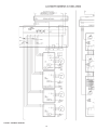
13
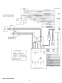
FIGURE 3. WIRING DIAGRAM
14
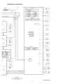
15
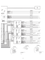
FIGURE 4. SCHEMATIC DIAGRAM
16
17
on the elapsed hours value at the time the error occurred. It is
displayed in hours and minutes. This error remains displayed as
long as it is still valid. When cleared it is moved to the Error
History Screen. The system will automatically jump to this screen
when an error is detected. It will also go to this screen upon
power-up if an error was still valid when power was turned off.
6. Use the UP or DOWN key to select the value you wish to enter.
7. Touch the SELECT key to accept and store the new value.
OPERATING DIFFERENTIAL SETPOINT
ADJUSTMENT PROCEDURE
NOTE: Errors are cleared from this screen by pressing the
"select" key.
Each of the stages has an independent Operating Differential Setpoint.
The range of these setpoints is from 1 Degree F to 50 Degrees F for
all models. Use the following procedure to change this setpoint:
•
Error History Screen:
This screen displays a list of the last 9 errors (with timestamps)
that have occurred. The last error to occur is displayed first. If a
new error occurs this screen is presented to display the error.
•
Reload Defaults Screen:
From this screen the user can restore the factory default values
for screen adjustable configurations by pressing the Select key.
The values restored are as follows:
1. Touch the MENU key.
2. Scroll the ">" with the DOWN key next to USER SETTING
SCREEN.
3. Touch the SELECT key.
4. Scroll the ">" with the DOWN key until it is pointing to
OPERATING DIFFERENTIAL SETPOINT.
GW Models
Oper Setpnt (Operating Setpoint) - 145° F (63° C)
Stage1 Diff (Operating Setpoint Differential) = 3° F (2° C)
Stage2 Diff (Operating Setpoint Differential) = 6° F (3° C)
Hi LImit (High LImit Setpoint) = 210° F (99° C)
Hi Limit Dif (High Limit Differential) = 20° F (11° C)
5. Touch the SELECT key.
6. Scroll the ">" with the DOWN key until it is pointing to the STAGE
you want.
7. Touch the SELECT KEY.
GB Models
Oper Setpnt (Operating Setpoint) = 190° F (88° C)
Stage1 Diff (Operating Setpoint Differential) = 3° F (2° C)
Stage2 Diff (Operating Setpoint Differential) = 6° F (3° C)
Hi LImit (High LImit Setpoint) = 230° F (110° C)
Hi Limit Dif (High Limit Differential) = 20° F (11° C)
8. Use the UP and DOWN key to select the value you wish to enter.
9. Touch the SELECT key to accept and store the new value.
•
•
•
Temperature Units:
Temperature can be displayed in either °F or °C units.
Both Models
Tempert Units (Temperature Units) = F
Post Cir Secs (Post Circulation pump delay = 45 seconds
Network Address (Network Address) = (non-valid address)
Post Circulate Delay Time:
The time circulation pump will stay on after the burner is turned off. The
time in seconds is adjustable with the following values: 45, 90, 180 or
continuous. If the continuous value is selected the pump will remain on
at all times and the post circulate state time will be set at 45 seconds.
UIM Touch Switches
Below the LCD display are five touch switches or keys, that the
operator uses to operate the system.
Network Address:
This is a unique number assigned to this boiler to differentiate it
from other boilers or water heater on the same A. O. Smith
proprietary network. A valid Network Address can be any number
from 1 to 31. It is set by default to zero, which is an invalid address.
The boiler will not communicate until it is changed to a valid and
unique number. This prevents two units from trying to respond
to the same request from the PC or supervisory network device.
•
Menu Key:
Pressing this key activates the menu screen where the other
screens can be accessed.
•
Select Key:
This key performs several functions. Screens can be selected
from the menu screen by pressing this key when the">" appears
next to the screen desired.
Configuration Settings Screen:
Displays the status of the dipswitches installed on all boards as
described on page 9.
On the User Settings screen items that appear next to a ">" symbol
can be selected with this key. If a setpoint configuration item is selected,
the ">" will then flash slowly to indicate that the item has been selected.
The Up and Down keys are then used to change its value.
Log & System Info Screen:
Displays the following information:
Elapsed hours of operation (Total time system has been powered
up)
Number of running minutes (Number of minutes system has been
in the run mode)
Number of cycles for each stage (Number of times stage has been
in heat mode).
Kbtu rating of the boiler (0 to 5750Kbtu in 10Kbtu increments)
The software revision level of the CCB, and FCB micro-controllers.
From the Current Error Screen this key is used to reset the system
from an error:
•
Current Error Screen:
• Displays the last error that the system has detected plus a
timestamp of when the error occurred. (The time stamp is based
18
Up and Down Keys:
These keys are used to move upwards and downwards in
screens to reach a desired item and to change setpoints and
user settings. They have an auto increment/decrement feature
for some of the configurations and values. When you first press
one of the keys and value changes by 1 count, then wait 1/2
second and changes slowly until the key is released or if held
for 3 or more seconds it will change the value quickly.
On multiple stage boilers there are also eight LED's on the lower
right that indicate the state of the individual FCB's. The red LED's
are only on when the main red LED is on and indicate which FCB
has the error. The green LED indicates when flame is proved on
that particular stage, unless the dipswitch for sensing flame is turned
off. Then the LED indicates that the gas valve has turned on.
Help Key:
Pressing the Help key from any screen displays helpful
information about that screen. From the menu screen, general
help information is displayed as to how to use the user interface.
To return to the previous screen press the Help or Select keys,
or press Menu key to go to the menu screen. If a small down
arrow appears in the lower right hand corner then there is off
screen content below what is displayed. Press the down arrow
to scroll down to this information. After scrolling down an up arrow
will appear in the upper right hand corner to indicate off screen
content above what is displayed.
Fault Messages and Troubleshooting Guide
The EMC5000 system does excessive self-diagnostics and displays
detected faults on the UIM display in an easy to read manner. There
are approximately 80 different faults that can be detected. Some of
the faults are caused by internal problems and some by external
causes. The faults create different types of system lockouts (shut
down). Hard lockouts are serious problems that require the user to
manually restart the system. Soft lockouts can be reset by the user
or after 60 minutes the system will automatically clear the error and
restart. Auto Reset lockouts will monitor the cause of the fault and if
the fault clears itself the system resets itself. Faults with Immediate
Reset lockouts are caused by faults that are momentary in nature.
The fault is recorded and the system immediately resets itself. The
following table shows the fault messages and some possible
troubleshooting hints:
UIM LED's
The three LED's to the right of the LCD indicate the status of the
overall system. The red LED indicates that a fault has been detected
and the system has stopped running. It is on continuously for soft
faults and flashes for hard faults. The Yellow LED indicates that the
boiler is in a ready mode waiting for a call for heat command. When
on continuously the Green LED indicates that the system is in the
heating mode. If it is flashing it indicates that the UIB is in the
initialization mode when the touch switches are being calibrated.
TROUBLESHOOTING IGNITION SYSTEM
Fault Messages and Lockout Status (* = stage number: 1 or 2)
Fault Displayed
Description
Red LED
Lockout
“Display Fail” Communications with UIM interrupted
Continuous
Auto Reset
•
Check communication cable to UIM. Try moving to other Internal Communications connector on CCB. Also check
the connectors where the cable is plugged in for best connecting wires.
“Comm. Fail Stg.*”
Communications with FCB interrupted
Continuous
•
Same as above. Also try swapping FCB and UIM communications cables.
Auto Reset
“Low AC Voltage”
Line voltage less than 90 vac
Continuous
Auto Reset
•
Check incoming power line for loss of voltage. May also be caused by a power line brown-out (momentary loss of
voltage)
“Low 24VAC” Voltage from transformer less than 18 vac
Continuous
Auto Reset
•
Check transformer output. Should be over 24vac. May be caused by excessive current drain or a faulty transformer
“Brown Out Reset”
Indicates a brown out reset occurred
---None
•
Caused by a momentary dip in voltage on the CCB +5vdc power bus. Contact factory. (Not considered a serious
problem if it only occurs on very rare occasions.)
“Timeout Reset”
Indicates a watchdog reset occurred
---None
•
Caused when the micro executes the software in an improper way. Contact factory. (Not considered a serious
problem if it only occurs on very rare occasions.)
“CCB Overflow”
Stack overflow - recorded in history only
---Immediate Reset
•
Caused when the micro overfills its memory stack. Contact factory. (Not considered a serious problem if it only
occurs on very rare occasions.)
“CCB Underflow”
Stack underflow - recorded its history only
---Immediate Reset
•
Caused when the micro underfills its memory stack. Contact factory. (Not considered a serious problem if it only
occurs on very rare occasions.)
“Sequence Err”
Incorrect flow of critical code
Flashing
HARD
•
Caused when the micro executes software code in an incorrect manner. Contact factory.
“A/D Fail CCB”
Error in analog input reading
Flashing
HARD
•
Caused when the Analog to Digital converter section of the micro operates improperly. Contact factory.
“EEProm Error”
Not implemented
----
None
“ROM Failure Stg*”
ROM contents incorrect
Flashing
HARD
•
Caused when the Read Only Memory on one of the FCB micros operates improperly. Contact factory.
19
“ROM Failure CCB”
ROM contents incorrect
Flashing
HARD
•
Caused when the Read Only Memory on the CCB micro operates improperly. Contact factory.
“Hdwr Short Stg**
FCB output pin shorted
Flashing
HARD
•
Caused when a pin on one of the FCB micros is not in the output state it should be in. Contact factory.
“Hdwr Short CCB”
CCB output pin shorted
Flashing
HARD
•
Caused when a pin on the CCB micro is not in the output state it should be in. Contact factory.
“CPU Fail Stg**
FCB processor failed internal check
Flashing
HARD
•
Caused when one of the FCB micros does not pass its internal checks. Contact factory.
“CPU Fail CCB”
CCB processor failed internal check
Flashing
•
Caused when the CCB micro does not pass its internal checks. Contact factory.
HARD
“RAM Failure CCB”
CCB Ram check failed
Flashing
HARD
•
Caused when the CCB micros Random Access Memory operates incorrectly. Contact factory.
“FCB Comm Timeout”
FCB did not receive command from CCB
Continuous
SOFT
•
Caused when communications between the CCB and the FCB are interrupted. May occur when a surge of power on
a nearby device (i.e. arc welder) creates an EMI burst. Not a serious problem if it occurs rarely.
“No Flow”
Water is not flowing
Continuous
SOFT
Caused by the flow switch being open when it should be closed. Check water lines, pump, flow switch contacts,
wiring.
“Blower Prov Stg*”
blower pressure is too low
Continuous
SOFT
•
Caused by either the High-Speed or Low-Speed blower prover switches being open when they should have been
closed. Check blowers, switch contacts, wiring, and for air leaks.
•
“Blocked Flue”Flue is Blocked
Continuous
SOFT
•
Caused by the blocked flue switch contacts being open when they should have been closed. Check for flue blockage,
switch contacts, wiring.
“High Limit”
•
Outlet temp. exceeded high limit setpoint
Continuous
Auto Reset
Caused when the temperature of the outlet probe exceeds the high limit setpoint. This is an internal “software” limit
switch and not an actual device. Check that the over temperature is not being caused by improper setup or operation
of the boiler.
“ECO fault”
•
Outlet temp is too high
Flashing
HARD
Caused when the ECO (a thermostat) contacts in the Outlet probe are open when they should be closed. Fault may
be due to high outlet temperature, bad switch contacts in the ECO, or disconnected wiring. Note: The ECO can be
checked by disconnecting the outlet probe from the CCB and reading the resistance across the two active pins on the
connector at the end of the probe cable. The value should be approximately 0 ohms when the temperature of the
probe is less than 220°F.
“Low Water”
•
Water level is too low
Flashing
HARD
Caused by the Low Water Cut Out device not closing its feedback switch contacts when it should. Check water line,
switch contacts, wiring, LW/CO.
“Low Gas”
•
Gas pressure is too low
Flashing
HARD
Caused by the Low Gas switch being open when it should be closed. Check gas line, switch contacts, wiring.
“IRI Gas”
IRI Gas Valve did not turn on
Flashing
HARD
Caused by the IRI Gas Valve not closing its feedback switch contacts when it should. Could also be caused by a
problem with the relay output on the CCB. Check output to IRI Gas Valve, switch contacts, wiring.
•
“Powered Vent”
Power vent not running
Flashing
HARD
•
Caused by the Powered Vent device not closing its feedback switch contacts when it should. Could also be caused
by a problem with the relay output on the CCB. Check output to powered vent, switch contacts, wiring.
“High Gas Stg*”
Gas pressure too high
Flashing
HARD
•
Caused by the High Gas switch being open when it should be closed. Check gas line, switch contacts, wiring.
“Inlet Probe” Inlet probe shorted or open
Flashing
HARD
•
Caused when the thermistor in the probe or the wiring to the probe is shorted or disconnected. Check the probe.
Note: The thermistor and wiring can be checked by disconnecting the probe from the CCB and reading the resistance
across the two active pins on the connector at the end of the probe cable. The value should be approximately 10K
ohms (value will change slightly with changes in temperature).
“Outlet Probe:”
Outlet probe shorted or open
Flashing
HARD
•
Caused when the thermistor in the probe or the wiring is shorted or disconnected. Check the probe. Note: the
thermistor and wiring can be checked by disconnecting the probe from the CCB and reading the resistance across
the two active pins on the connector at the end of the probe cable. The value should be approximately 10K ohms
20
(value will change slightly with changes in temperature).
“Tank Probe”
Tank (Remote) probe shorted or open
Flashing
HARD
•
Caused when the thermistor in the probe or the wiring is shorted or disconnected. Check the probe. Note: the
thermistor and wiring can be checked by disconnecting the probe from the CCB and reading the resistance across
the two active pins on the connector at the end of the probe cable. The value should be approximately 10K ohms
(value will change slightly with changes in temperature).
“Igniter Stg*” Igniter current is too low
Flashing
HARD
•
Caused by a low current draw problem with the igniter. This may occur if the igniter is old, damaged,
or disconnected and no longer draws the proper level of current. This condition will affect the ability of the igniter to
get hot enough to fire the gas properly. Check the igniter and its associated wiring.
“Igniter Pwr Stg*”
Improper power applied to igniter circuit
Flashing
HARD
•
Caused by improper line power being applied to the igniter circuitry. Check line connections. Paying particular
attention to the earth ground connection. Also check that line voltage does not exceed 132 vac rms.
“Igniter Hdwr Stg*”
Hardware problems with igniter circuit
Flashing
HARD
"Gas Relay Stg*"
Gas Valve Relays did not turn on
Flashing
HARD
"Flame Stg*"
Flame not detected
Flashing
HARD
"Blwr Low Stg*"
Low speed blower relay did not turn on
Flashing
HARD
•
Caused by a failure of a relay on the FCB. Contact factory.
"Blwr Hi Stg*" High speed blower relay did not turn on
Flashing
HARD
•
Caused by a failure of a relay on the FCB. Contact factory.
"Short Cycle Cond."
Burner cycle rate above 30 per hour
SEE BELOW
---•
Caused when a stage performs more than 30 heat cycles in one hour. When this fault is detected the system continues
to operate but the calls for heat are forced to occur no faster than every 180 seconds. While this system is in this short cycle
operating mode the yellow "Standby" LED flashes. Check system setup and operation.
Other troubleshooting hints:
1. Input switches can be easily checked by observing their activation on the UIM System Status screen. Force the boiler to remain
in the Standby mode by opening the Thermostat input or by setting the operating setpoint to the minimum so that the system
does not request heat. Then short out the contacts on the switch and verify that an asterisk "*" appears next to the appropriate
input on the screen. If it does not then look for the problem to be in the wiring or connectors between the switch and the CCB.
2. When troubleshooting a particular problem the heating sequence time can be shortened by turning off the dipswitches for
operation devices that are not needed during troubleshooting.
3 The pump can be activated during the "Standby" mode by changing the post-circulate time too continuous.
4. All Hi-Speed blowers can be activated for 5 minutes by opening any Hi-Speed blower prover switch prior to turning on the power.
This activates the "shutter adjust" mode. During this time, activation of all of the blower prover switches can be checked on the
"system status" screen.
5. Opening the Thermostat input leads will force the system to remain in the standby mode.
6. Running the system with the gas turned off will allow the system to run through all operating steps up to flame sensing.
7. Proper operation of the flame sensing circuit can be almost completely verified through the use of a 14007 diode. The anode
end of the diode should be connected to the appropriate flame sense lead and the cathode end (bar) of the diode should be
connected to the case of the boiler (earth ground connection). Gas is not needed for this procedure and therefore should be off.
It is also desirable to disable the command for heat by opening the thermostat leads. After apply power the system should
declare an error because flame is being sensed at the wrong time. Shift to the "System Status" screen and scroll down to the
appropriate "Flame" input. The asterisk "*" should appear when the diode is connected and not when it is disconnected.
8. The CCB can be individually checked out be setting the 10 position CCB dipswitch to off. This will make the system operate as
a single stage and disable the other FCB's.
9. Watching the Control States screen while troubleshooting the heating sequence will help determine what is causing the problem.
Knowing what state the CCB and FCB's are in when the problem occurs will help to pinpoint a possible source of the fault.
10.Write down the proper positions of the dip switches after initial installation and compare them to the present dipswitch setting
shown on the "Configuration Settings" screen. This will catch any accidental changing of the dipswitches.
21
MAIN BURNERS
DANGER
HOT WATER TEMPERATURES REQUIRED FOR AUTOMATIC
DISHWASHER AND LAUNDRY USE CAN CAUSE SCALD BURNS
RESULTING IN SERIOUS PERSONAL INJURY AND/OR DEATH.
THE TEMPERATURE AT WHICH INJURY OCCURS VARIES WITH
THE PERSON'S AGE AND TIME OF EXPOSURE. THE SLOWER
RESPONSE TIME OF CHILDREN, AGED OR DISABLED
PERSONS INCREASES THE HAZARDS TO THEM. NEVER
ALLOW SMALL CHILDREN TO USE A HOT WATER TAP, OR TO
DRAW THEIR OWN BATH WATER. NEVER LEAVE A CHILD OR
DISABLED PERSON UNATTENDED IN A BATHTUB OR SHOWER.
Check main burners every three months for proper flame
characteristics.
The main burner should display the following characteristics:
• Provide complete combustion of gas.
• Cause rapid ignition and carry over of flame across entire burner.
• Give reasonably quiet operation during initial ignition,
operation and extinction.
• Cause no excessive lifting of flame from burner ports;
see Figure 5.
FIGURE 5. BURNER FLAME CHARACTERISTICS
THE WATER HEATER SHOULD BE LOCATED IN AN AREA
WHERE THE GENERAL PUBLIC DOES NOT HAVE ACCESS TO
SET TEMPERATURES.
If the preceding burner characteristics are not evident, check for
accumulation of lint or other foreign material that restricts or blocks
the air openings to the burner or boiler.
IT IS RECOMMENDED IN DOMESTIC HOTWATER
APPLICATIONS THAT LOWER WATER TEMPERATURES BE
USED TO AVOID THE RISK OF SCALDING. IT IS FURTHER
RECOMMENDED, IN ALL CASES, THAT THE WATER
TEMPERATURE BE SET FOR THE LOWEST TEMPERATURE
WHICH SATISFIES THE USER'S HOT WATER NEEDS. THIS
WILL ALSO PROVIDE THE MOST ENERGY EFFICIENT
OPERATION OF THE BOILER AND MINIMIZE SCALE
FORMATION IN THE HEAT EXCHANGER, THUS PROLONGING
THE LIFE OF THE BOILER.
NOTE: Cleaning of main burners.
1.
2.
3.
4.
Shut off all gas and electricity to unit. Allow boiler to cool.
Remove main burners from unit.
Check that burner venturi and ports are free of foreign matter.
Clean burners with bristle brush and/or vacuum cleaner.
DO NOT distort burner ports.
5. Reinstall burners in unit. Ensure that all the screws on the burner
flange are tightened securely so that the gasket will provide a
good seal. Also, ensure that each orifice is centered with the
venturi opening of every burner.
Note: Make sure the washer of each pre-jet orifice is inserted
at least 1/4 into the burner tube and that it is not touching
the sides of the burner tube. This is critical for proper
operation, see Figure 6.
SETTING THE WATER HEATER TEMPERATURE AT 120°F (49°C)
WILL REDUCE THE RISK OF SCALDS. SOME STATES/
PROVINCES REQUIRE SETTINGS AT SPECIFIC LOWER
TEMPERATURES. TABLE 1 BELOW SHOWS THE
APPROXIMATE TIME-TO-BURN RELATIONSHIP FOR NORMAL
ADULT SKIN.
6. Check for good flow of combustion and ventilating air to the
unit.
TABLE 1. Risk of Scalds
Temperature
Setting
Time to Produce 2nd & 3rd
Degree Burns on Adult Skin
Over 170°F (77°C)
Nearly instantaneous
160°F (71°C)
About 1/2 second
150°F (66°C)
About 1-1/2 seconds
140°F (60°C)
Less than 5 seconds
130°F (54°C)
About 30 seconds
120°F (49°C) or less
More than 5 minutes
USE ANTI-SCALD VALVE(S) in the hot water system to reduce the
risks of scalding at points of use such as lavatories, sinks and bathing
facilities.
FIGURE 6. BURNER/ORIFICE INSERTION
22
After placing the boiler in operation, check the ignition system safety
shut-off devices for proper operation. To accomplish this with the
main burners operating, close the valve on the manifold. Within
four seconds the main burners should extinguish. If this does not
occur immediately, discontinue gas supply by closing main manual
shut-off and call a qualified serviceman to correct the situation. If
the burners extinguish, then light boiler in accordance with lighting
and operating instructions.
Inspect the external surfaces of the vent system every 6 months for
corrosion and leakage. Inspect the vent terminations for corrosion
and foreign matter (including ice) which may be blocking the
exhausting flue products. Call a qualified service agent to replace
or repair any corroded or leaking parts.
For installations above 4500 feet (1350 m), refer to HIGH ALTITUDE
INSTALLATIONS in the Installation Manual (P/N 212511-000).
DELIMING
Qualified service agent must inspect internal surfaces of the vent
system and the boiler at least once a year.
The amount of calcium carbonate (lime) released from water is in
direct proportion to water temperature and usage. The higher the
water temperature or water usage, the more lime deposits are
dropped out of the water. This is the lime scale which forms in
pipes, boilers and on cooking utensils.
DO NOT STORE COMBUSTIBLE MATERIALS, GASOLINE, OR
OTHER FLAMMABLE VAPORS, LIQUIDS IN THE AREA OF THE
APPLIANCE. NONCOMPLIANCE MAY RESULT IN FIRE OR
EXPLOSION. DO NOT OBSTRUCT THE FLOW OF COMBUSTION
OR VENTILATION AIR TO THE APPLIANCE.
The usage of water softening equipment greatly reduces the
hardness of water. However, this equipment does not always remove
all of the hardness (lime). For this reason it is recommended that a
regular schedule for deliming be maintained.
CHEMICAL VAPOR CORROSION
Boiler corrosion and component failure can be caused by airborne
chemical vapors. Spray can propellants, cleaning solvents,
refrigerants, calcium or sodium chloride (water softener salts), waxes,
chlorine and process chemicals are typical compounds that are
potentially corrosive. These materials are corrosive at very low
concentration levels with little or no odor to reveal their presence.
Products of this sort should not be stored near the boiler. Air which
is brought in contact with the boiler should not contain any of these
chemicals. The boiler should be provided with air from outdoors
when installed in environments having corrosive atmospheres.
The time between cleaning will vary from two to six months
depending upon water conditions and usage. A change of
approximately 5°F (3°C) in the normal temperature rise through the
boiler is usually an indication that scale should be removed. For
long life, copper or brass is recommended for all valves, pipe and
fittings.
CAUTION
CIRCULATION PUMP
LIME ACCUMULATION CAN REDUCE THE LIFE OF THE
EQUIPMENT, REDUCE EFFICIENCY AND WASTE FUEL. BOILER
FAILURE DUE TO LIME OR SCALE BUILDUP VOIDS THE
WARRANTY.
Refer to the pump manufacturer's schedule of maintenance for
frequency and method of lubricating the pump and motor. Inspect
the pump once a month for leaky mechanical seals and/or O-rings
and loose or damaged components. Contact a qualified service
agent to replace or repair parts as required.
COMBUSTION AIR BLOWER
The bearings in the motor are pre-lubricated and sealed at the
factory. The bearings should be oiled once every six months per
the manufacturer's recommended maintenance schedule. Use SAE29 non-detergent oil.
BLOCKED VENT SHUT-OFF SYSTEM
The boiler is equipped with a blocked vent shut-off system which
will close the gas valve and shut off the main burner gas when there
is excessive pressure pressuring the vent system due to a partially
or completely blocked vent. The display on the front panel will
indicate this failure condition.
RELIEF VALVE
The safety relief valve should be opened at least twice a year to
check its working condition. This will aid in assuring proper pressure
relief protection. Lift the lever at the top of the valve several times
until the valve seats properly and operates freely.
DO NOT ATTEMPT TO OPERATE THE BOILER if this situation
occurs. Shut the boiler off before performing all the steps shown in
"TO TURN OFF GAS TO APPLIANCE" section of the Lighting and
Operating Instructions.
DANGER
THE WATER PASSING OUT OF THE VALVE DURING CHECKING
OPERATION MAY BE EXTREMELY HOT. BEFORE OPERATING
RELIEF VALVE, MAKE SURE DRAIN LINE IS INSTALLED TO
DIRECT DISCHARGE TO A SAFE LOCATION SUCH AS AN OPEN
DRAIN, TO AVOID SCALDING OR WATER DAMAGE.
Contact a qualified service agent to inspect the unit and vent system
and correct the problem.
VENT SYSTEM
The flue products are corrosive in nature and if the boiler is vented
horizontally the flue gases are at a higher pressure than the
surrounding air pressure. Inspection of the boiler and vent system
is necessary to insure that flue gas leakage to the surrounding area
does not occur.
WARNING
SHOULD OVERHEATING OCCUR OR THE GAS SUPPLY FAIL TO
SHUT OFF, TURN OFF THE MANUAL GAS CONTROL VALVE TO
THE APPLIANCE.
23
NEW BOILER LIMITED WARRANTY
A. O. Smith Corporation, the warrantor, extends the following LIMITED WARRANTY to the owner of this hydronic boiler:
1.
If within TEN years after initial installation of the boiler, the heat exchanger shall prove upon examination by the warrantor to be defective in material
or workmanship, the warrantor, at his option, will exchange or repair such part or portion. This term is reduced to FIVE years if this boiler is used for
volume hot water supply purposes other than hydronic space heating.
a. This warranty is extended to the owner for all other parts or portion during the FIRST year following initial installation of this boiler.
b. The warranty on the repair or replacement of the part or portion will be limited to the unexpired term of the original warranty.
2.
CONDITIONS AND EXCEPTIONS
This warranty shall apply only when the boiler is installed in accordance with local plumbing and building codes, ordinances and regulations, the
printed instructions provided with it and good industry practices. In addition, an appropriately sized safety relief valve certified to the ASME Boiler and
Pressure Vessel Code must have been installed and fresh water used for filling and makeup purposes;
a. This warranty shall apply only when the boiler is used:
(1) at temperatures not exceeding the maximum setting of its operative and/or high limit control;
(2) at water pressure not exceeding the working pressure shown on the boiler;
(3) when filled with boiler water, free to circulate at all times and with the heat exchanger free of damaging scale deposits;
(4) in a noncorrosive and non-contaminated atmosphere;
(5) in the United States, its territories or possessions, and Canada;
(6) at a water velocity flow rate, not exceeding or below the Boiler's designed flow rates;
b. Any accident to the boiler, any misuse, abuse (including freezing) or alteration of it, any operation of it in a modified form will void this warranty.
3.
SERVICE AND REPAIR EXPENSE
Under this limited warranty the warrantor will provide only a replacement part. The owner is responsible for all other costs. Such costs may include
but are not limited to:
a. Labor charges for service removal, repair or reinstallation of the component part;
b. Shipping, delivery, handling, and administrative charges for forwarding the replacement part from the nearest distributor and returning the
claimed defective part to such distributor.
c. All cost necessary or incidental for any material and/or permits required for installation of the replacement.
4.
LIMITATIONS ON IMPLIED WARRANTIES
Implied warranties, including any warranty of merchantability imposed on the sale of this boiler under state law are limited to one (1) year duration for
the boiler or any of its parts. Some states or provinces do not allow limitations on how long an implied warranty lasts, so the above limitation may not
apply to you.
5.
CLAIM PROCEDURE
Any claim under the warranty should be initiated with the dealer who sold the boiler, or with any other dealer handling the warrantor’s products.
If this is not practical, the owner should contact:
U.S. Customers
A. O. Smith Water Products Company
500 Tennessee Waltz Parkway
Ashland City, TN 37015
Telephone: 800-323-2636
a.
b.
6.
Canadian Customers
A. O. Smith Enterprises Ltd.
P. O. Box, 310 - 768 Erie Street
Stratford, Ontario N5A 6T3
Telephone: 800-265-8520
The warrantor will only honor replacement with identical or similar parts thereof which are manufactured or distributed by the warrantor.
Dealer replacements are made subject to in-warranty validation by warrantor.
DISCLAIMERS
NO OTHER EXPRESS WARRANTY HAS BEEN OR WILL BE MADE ON BEHALF OF THE WARRANTOR WITH RESPECT TO THE
MERCHANTABILITY OF THE BOILER OR THE INSTALLATION, OPERATION, REPAIR OR REPLACEMENT OF THE BOILER. THE WARRANTOR
SHALL NOT BE RESPONSIBLE FOR WATER DAMAGE, LOSS OF USE OF THE UNIT, INCONVENIENCE, LOSS OR DAMAGE TO PERSONAL
PROPERTY OR OTHER CONSEQUENTIAL DAMAGE. THE WARRANTOR SHALL NOT BE LIABLE BY VIRTUE OF THIS WARRANTY OR
OTHERWISE FOR DAMAGE TO ANY PERSONS OR PROPERTY, WHETHER DIRECT OR INDIRECT, AND WHETHER ARISING IN CONTRACT
OR TORT.
a. Some states or provinces do not allow the exclusion or limitation of the incidental or consequential damage, so the above limitations or exclusions
may not apply to you.
b. This warranty gives you specific legal rights, and you may also have other rights which vary from state to state or province to province.
Fill in the following for your own reference. Keep it. Registration is not a condition of warranty. The model and serial number are found on the boiler’s rating
plate.
Owner______________________________________________________________________________________________________________________
Installation Address________________________________________________________________________________________________________
City and State or Province ___________________________________________________________________________________________________
Date Installed
___________
Model No.
___________________________
Serial No. ____________________________
Dealer’s Name______________________________________________________________________________________________________________
Dealer’s Address__________________________________________________________________Phone No. ________________________________
FILL IN WARRANTY AND KEEP FOR FUTURE REFERENCE
24