1
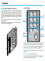
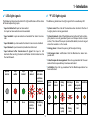
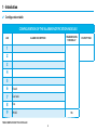
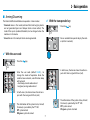
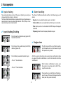
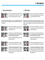
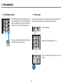
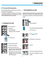
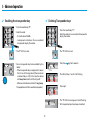
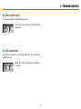
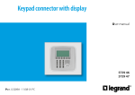
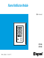
Alarms Notification Module
User manual
1
2
3
4
5
6
7
8
9
0
5739 54
5739 55
Part. U3628A - 11/08-01 PC
Contents
1. Introduction
■ The Alarms Notification Module
✔ User interface
✔ LEDs light signals
✔ “P” LED light signals
✔ Configuration table
4
4
5
5
6
2. Basic operation
■ Arming/Disarming
✔ With the user code
✔ With the transponder key
■ Inputs choking
✔ Inputs Enabling/Disabling
■ Alarms handling
✔ Burglar alarm
✔ Technical Fault Alarm
✔ PANIC Alarm
✔ Anti-tamper alarm
✔ Alarm stop
7
7
7
8
8
8
8
9
9
10
10
3. Advanced operation
■ The code and the transponders
✔ Customizing the user code
✔ Retrieving the factory set code
✔ Enabling the transponder key
✔ Deleting Transponder keys
■ Silencing the keys
■ LED suppression
11
11
11
12
12
13
13
4. Maintenance and troubleshooting
3
1 - Introduction
✔ User interface
■ The Alarms Notification Module
The Alarms Notification Module is a safety device, capable of notifying
burglary, technical faults and panic alarms locally and send them to the
Video Handset and to the Switchboard, where they will be displayed.
The Alarms Notification Module is capable of handling 8 independent inputs and one additional input dedicated to panic alarm signals
(PANIC).
Each input can be enabled or disabled. Its state is indicated by the
corresponding LED.
The system can be armed/disarmed by entering the 5 digit numeric
code or by using a transponder key.
LED
Keypad
“P” key
with LED
Transponder
reader
PANIC key
• LED: Leds 1 – 8 provide alarm notification from the burglary and technical faults inputs, LED 9 is dedicated to the panic alarm notification.
• Needle key with LED: this key gives access to the starting up procedure, Code/Transponder set up and Resetting of the Module.
• PANIC key: it generates an emergency call, even with the system
disarmed.
• Transponder reader: Transponder keys reader.
• Keypad: numeric keys for entering the user code. The
access to the arming/disarming procedure.
4
key gives
1 - Introduction
✔ LEDs light signals
✔ “P” LED light signals
The following tables describe the LEDs light notifications of the states
of the corresponding inputs.
The following table show the light signals for the needle key LED.
• Input not detected: input not connected.
• System armed: the state of the module when technical fault and
• Input enabled: input connected and enabled for alarm transmis-
• System disarmed: state of the Module when technical fault and bur-
An input not connected cannot be enabled.
burglary alarms can be generated.
sion.
glary alarms are not generated (panic and tamper alarms remain
active). The state of the inputs (enabled/disabled) can be changed
when the module is in this mode.
• Input disabled: input connected but alarm transmission disabled.
• Input alarmed: input connected, enabled and alarmed.
• Input alarmed after transmission of signal: the input is still
• Arming phase: it shows the passing of the output timing.
• Anti-tamper alarm: notification that the Module has been tam-
alarmed after sending the alarm notification to the Handset and to
the Switchboard.
pered with.
• Code/transponder management: the set up procedure for the user
code or the transponder keys have been activated.
• Installation: the start up procedure for the Module operation has
Input not
detected
Off
Input
enabled
Red
Input
disabled
Green
Input
alarmed
Red flashing
quickly +
Buzzer on
been activated.
Input alarmed
after alarm
notification
transmission
Red flashing
slowly
5
System
armed
System
disarmed
Arming
phase
Anti-tamper
alarm
Off
Green
Red
flashing
quickly
Red
flashing
slowly
Codes/
Installation
transponders
management
Deep
Red
Orange
1 - Introduction
✔ Configuration table
CONFIGURATION OF THE ALARMS NOTIFICATION MODULE
LED
TRANSMISSION
TIME DELAY
ALARM DESCRIPTION
1
2
3
4
5
6
Flood
7
Gas leak
8
Fire
9
PANIC
10 s
TO BE COMPLETED BY THE INSTALLER
6
OUTPUT TIME
2 - Basic operation
■ Arming/Disarming
✔ With the transponder key
The Alarms Notification Module can operate in 2 main modes:
• Disarmed: when in this mode, technical fault and burglary alarms
• Press the
• Armed: when in this mode, all alarms can be generated.
• Run an enabled transponder key by the read-
are not generated (panic and tamper alarms remain active). The
state of the inputs (enabled/disabled) can be changed when the
module is in this mode.
key
er (within 4 seconds).
✔ With the user code
• Press the
key
• In both cases, the device shows the active in-
• Enter the user code (default 12345) , to
puts with their assigned LEDs on (red).
change the mode of operation. Once the
code has been entered, a confirmation beep
will be heard:
- short beep, correct code entered
- long beet, wrong code entered
• In both cases, the device shows the active inputs with their assigned LEDs on (red).
• The information of the system status, Armed/
Disarmed, is provided by the “P” LED.
Off: system armed
ON green: system disarmed
• The information of the system status, Armed/
Disarmed, is provided by the “P” LED.
Off: system armed
ON green: system disarmed
7
2 - Basic operation
■ Inputs choking
■ Alarms handling
The enabling/disabling status of the inputs (choking) can only be
changed when the system is disarmed.
The Alarms Notification Module is capable of distinguishing between a
connected and a non connected (not detected - LED off) input. A non
connected input cannot be enabled.
The Alarms Notification Module notifies the following types of
alarms:
• Burglar: when an enabled burglary input is activated;
• Technical fault: when an enabled technical fault input is activated;
• Panic: when input no. 9 is activated or the PANIC key on the keypad
is pressed;
• Tampering: when the anti-tamper protection is open.
✔ Inputs Enabling/Disabling
• Press the key of a disabled input (green LED)
to enable it (red LED).
✔ Burglar alarm
• Press the key of an enabled input (red LED) to
• The LED assigned to this input flashes quickly
disable it (green LED).
and the device emits a short acoustic signal
that repeats every second.
• Press the 0 key to enable/disable all inputs
After the waiting time delay has expired (see configuration table
on page 6) the alarm notification is sent to the Handset and to the
Switchboard.
st
- Press a 1 time to Enable
• After the alarm notification has been sent,
the acoustic signal stop and the LED’s flashing will become slow.
- Press a 2nd time to Disable
• To remove the visual notification of the alarm,
press the key of the input that generated the
alarm (with the system disarmed).
8
2 - Basic operation
✔ Technical Fault Alarm
✔ PANIC Alarm
• The LED assigned to the technical fault input
• The LED 9, assigned to the alarmed input
After the waiting time delay has expired (see configuration table
on page 5) the alarm notification is sent to the Handset and to the
Switchboard.
After the waiting time delay has expired (10 seconds), the alarm
notification is sent to the Handset and to the Switchboard. The alarm
response handling procedure is then referred to the Caretaker’s Lodge
Switchboard.
• After the alarm notification has been sent,
• After the alarm notification has been sent,
• To remove the visual notification of the alarm,
• To remove the visual notification of the alarm,
The Alarms Notification Module carries out the
following operations:
The Alarms Notification Module carries out the
following operations:
- If the cause that generated the alarm is not resolved: the visual notification is not removed.
- If the cause that generated the alarm is not resolved: the visual notification is not removed.
- If the cause that generated the alarm has been
resolved: the visual notification is removed.
The device will also send a technical fault
alarm reset notification to the Handset and to
the Switchboard.
- If the cause that generated the alarm has been
resolved: the visual notification is removed.
The device will also send a technical fault
alarm reset notification to the Handset and to
the Switchboard.
flashes quickly and the device emits a short
acoustic signal that repeats every second.
flashes quickly and the device emits an acoustic signal that will last 10 seconds.
the acoustic signal stop and the LED’s flashing will become slow.
the acoustic signal stop and the LED’s flashing will become slow.
press the key of the input that generated the
alarm (with the system disarmed).
press the key of the input that generated the
alarm (with the system disarmed).
9
2 - Basic operation
✔ Anti-tamper alarm
✔ Alarm stop
• If the Alarms Notification Module is tampered
To stop an alarm before this is sent to the Handset and to the Switchboard, within the time limit specified by the configuration:
with, a notification is sent to the Handset and
to the Switchboard. At the same time the “P”
LED will turn red and start flashing slowly.
• Press the
• To remove the notification, reset the tamper-
key
• Enter the user code (default 12345).
ing contact and arm the system.
or
• Run an enabled transponder key by the
reader.
10
3 - Advanced operation
■ The code and the transponders
✔ Retrieving the factory set code
The Alarm Notification Module can accept only one user code (5 numeric digits) and 10 transponder keys.
The code (factory set to 12345) can be changed at any time. To replace a
transponder key after the maximum number of keys has been reached,
all keys need to be deleted and then re-registered.
Reinstating of the factory set user code (if the current code has been
forgotten) can be done following the procedure below, provided
that a registered transponder key is available (otherwise contact the
installer).
✔ Customizing the user code
• Press the needle key “P”.
• Press the needle key “P”.
• Enter the code:
• Run an enabled transponder key by the reader.
• The “P” LED turns red
- First activation: 12345
- Subsequent activations: personal code
• Press the
• The “P” LED turns red
for 5 seconds.
• The LEDs of keys 1 and 2 start flashing.
• Enter the new code (eg.: 99999)
• The device will emit a sound.
• Re-enter the new code (eg.: 99999)
• Press key 2.
- If the code has been re-entered correctly,
2 beep will be heard and the LED will go off.
• The “P” LED turns orange and starts flashing.
• The factory set code 12345 has now been
- If the code has been re-entered incorrectly, 1
1 long beep will be heard and the procedure
will need to be repeated.
activated.
11
3 - Advanced operation
✔ Enabling the transponder key
✔ Deleting Transponder keys
• Press the needle key “P”.
• Press the needle key “P”.
• Enter the code or run an enabled transponder
• Enter the code:
- First activation: 12345
key by the reader.
- Subsequent activations: Run an enabled
transponder key by the reader.
• The “P” LED turns red.
• The “P” LED turns red.
• Run a transponder key to be enabled by the
• Press the
key for 5 seconds.
reader:
- If the transponder key is recognised, it means
that it can still be registered (the maximum
number of keys is 10). In this case the device
will beep twice and the LED will go off.
• The LEDs of keys 1 and 2 start flashing.
- Otherwise the device will emit 1 long beep.
• Press key 1.
The procedure will then need to be repeated.
• The “P” LED turns orange and starts flashing.
• All transponder keys have been cancelled.
12
3 - Advanced operation
■ Silencing the keys
It is possible to enable/disable the keys’ sound.
• Press key 1 for 5 seconds, to enable/disable
the sound.
■ LED suppression
It is possible to suppress the display of the LEDs status when the
system is armed.
• When the system is disarmed, press key 2 for
5 seconds.
13
4 - Maintenance and troubleshooting
✔ A false alarm is received by a system sensor
The sensor is probably faulty: choke the zone and contact the
installer.
✔ I have forgotten the user code
Retrieve the factory set code (see page 11).
✔ I have lost a transponder key
Cancel all transponders and re-register the ones to be used
(see page 12).
14
World Headquarters and
International Department
87045 LIMOGES CEDEX FRANCE
: 33 5 55 06 87 87
Fax : 33 5 55 06 74 55
www.legrandelectric.com
Legrand reserves at any time the right to modify the contents of this booklet and to communicate, in any form
and modality, the changes brought to the same.
Installer stamp