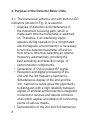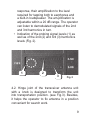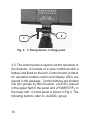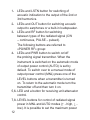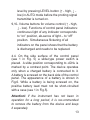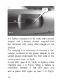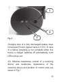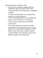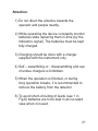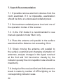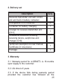
1
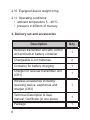
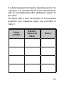
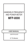
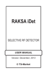
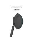
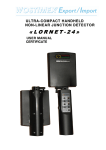
HANDHELD NON-LINEAR
JUNCTION DETECTOR
«LORNET»
USER MANUAL
CERTIFICATE
© TS-Market
Contents
USER MANUAL...........................................3
1. Introduction.............................................3
2. Specifications:........................................4
3. Delivery set and accessories................6
4. Purpose of the Detector Basic Units....8
5. Safety Measures...................................18
6. Operation Order....................................18
7. Search Recommendation....................22
CERTIFICATE............................................24
1. General..................................................24
2. Delivery set...........................................25
3. Warranty................................................25
6. Importer:................................................26
7. Claims Data...........................................26
2
USER MANUAL
1. Introduction
The non-linear junction detector “LORNET” (further
NLJD) is used for search and location of electronic
devices both in active and switch-off state. The
detector opera-tion is based on the property
of semiconductor components to generate a
response at the 2d and 3d harmonics when
radiated by an RF probing signal. Semiconductor
components of artificial origin will have a higher
level second harmonic while semi-conductor
components of natural origin (e.g. oxide films) will
have a higher level third harmonic respectively. An
NLJD analyzes the 2d and 3d harmonics response
of the radiated objects, which enables a quick and
reliable identification of electronic devices and
natural oxide semiconductors.
The NLJD “LORNET” automatically finds the best
receiving frequency channel free of noise and
distortion providing flawless operation even in
the complicated electro-magnetic environment.
The frequency tuning algorithm implemented in
“LORNET” automatically selects the RF probing
signal frequency such that the noise level in 2d
harmonic receiving channel is held minimal, while
3
digital processing of a demodulated signal gives
maximum sensitivity.
There are two types of radiated signals:
• continuous wave carrier (CW);
• pulse modulated carrier with a duty ratio
44 (pulse).
This enables to combine wide detection range and
reliable identification of the devices found. Output
power automatic control mode significantly
simplifies
operator’s
work.
“LORNET”
simultaneously displays the 2d and 3d harmonics
levels at its LED panel. Besides, the 2d and 3d
harmonics levels can be estimated in turn aurally
by click repetition rate reproduced through a
built- in loudspeaker or wireless earphones.
2. Specifications:
2.1. Radiated signal types:
• continuous wave carrier;
• pulse modulated carrier with a duty ratio 44.
2.2. Carrier frequency step 0.2MHz within a tuning
range of (890 … 891)MHz.
Automatic frequency selection. Possibility of
radiation at the carrier frequency with a minimum
noise level in the 2d harmonic receiver path.
4
2.3. Maximum radiated power in
the CW mode ≤2W
2.4. Peak radiated power in the pulse
mode ≤10W.
2.5. Manual or automatic control of the radiated
power level.
Dynamic control range of 30dB down from the
maximum output power value with 11 level
gradations.
2.6. Receivers sensitivity better than –150dBW
given a 10dB signal to noise ratio.
2.7. Receivers tuning frequencies equal to the
transmitter double and triple frequencies.
2.8. Receiving path dynamic range ≥ 70dB.
2.9. Time of continuous operation with a lithium-Ion
battery at the maximum radiated power:
• ≥ 3 hours in the pulse mode;
• ≥ 1,5 hours in the CW mode.
• unlimited operation time from 220V mains
with a power adapter connected.
5
2.10. Equipped device weight ≤1kg.
2.11. Operating conditions:
• ambient temperature 5…40°C;
• pressure ≥ 450mm of mercury.
3. Delivery set and accessories
6
Description
Q-ty
Receiver-transmitter unit with control
unit and built-in battery container
1
Changeable Li-Ion batteries
2
Container for battery charging
1
Charger for receiver-transmitter unit
(CH1)
1
Wireless accessories including:
receiving device, earphones and
charger (CH2)
1
Technical Description & User
manual, Certificate (in one piece)
1
Package
1
The device
appearance is
shown in Fig. 1,
where:
1- LED indicator;
2-Transceiver
antenna unit
combined with
an indicator;
1
2
3-Telescopic
arm;
4- Control panel
with a power
section and a
battery (fixed
underneath).
Wireless
earphones,
chargers and
additional batteries
are not shown in
the figure.
Fig. 1
3
4
7
4. Purpose of the Detector Basic Units
4.1. The transceiver antenna unit with built-in LED
indicators (shown in Fig. 2) is used for:
• Analysis of distortion and interference in
the instrument receiving path, which is
made each time the transmitter is switched
on. Therefore, if an interfering signal
appears during operation (in a complicated
electromagnetic environment) it is necessary
to turn the detector transmitter off and on
from time to time thus selecting an optimal
frequency automatically, providing the
best sensitivity and detection range of
semiconductor components.
• Generation of CW or pulsed RF signal.
• Reception and digital processing of the
2nd and the 3rd frequency harmonics.
Simultaneous display of the 2nd and the
3rd harmonics levels gives the opportunity
to distinguish with a high reliability between
signals of artificial semiconductors integrated
in electronic devices and natural corrosive
ones which appear at oxidation of connecting
points of various metals.
• Demodulation of the 2nd and 3rd harmonics
8
response, their amplification to the level
required for tapping both to earphones and
a built-in loudspeaker. The am-plification is
adjustable within a 20 dB range. The operator
can listen to demodulated signals of the 2nd
and 3rd harmonics in turn.
• Indication of the probing signal levels (1) as
well as of the 2nd (2) and 3rd (3) harmonics
levels (Fig. 2).
1
2
3
Fig. 2
4.2. Hinge joint of the transceiver antenna unit
with a knob is designed to transform the unit
into transportation position. (see Fig.3). Besides,
it helps the operator to fix antenna in a position
convenient for search work.
9
1
2
Fig. 3: 1- Fixing device; 2- Hinge joint.
4.3. The control panel is used to control operation of
the detector. It consists of a case combined with a
battery and fixed on the arm. Control board, buttons
for operation modes control and display LEDs are
placed in the package. Control buttons are divided
into two groups by their function: «AUDIO» placed
in the upper half of the panel and «POWER RF» in
the lower half. Control panel is shown in Fig.4 The
following buttons refer to «AUDIO» group:
10
1
10
2
9
3
8
4
7
5
6
Fig. 4
11
1- LEDs and LSTN button for switching of
acoustic indication to the output of the 2nd or
3rd harmonics.
2- LEDs and OUT button for switching acoustic
output to earphones or a built-in loudspeaker.
3- LEDs and RF button for switching
between types of the radiated signal (CW
– continuous, PULSE – pulsed).
The following buttons are referred to
«POWER RF» group:
4- LEDs and PWR button to switch on/off
the probing signal transmitter. When the
instrument is switched on the automatic mode
of output power control (AUTO) is set by
default. To switch over to a manual mode of
output power control (MNL) press one of the
LEVEL buttons when a transmitter is turned
on. To return to the automatic mode turn the
transmitter off and then turn it on.
5,6- LED and a button for receiving unit attenuator
control.
7,8- LEVEL buttons for control of radiated signal
power in MNL and AUTO modes (↑ - high, ↓ low). It is possible to set the maximum power
12
level by pressing LEVEL button (↑ - high, ↓ low) in AUTO mode before the probing signal
transmitter is turned on.
9,10- Volume buttons for volume control (↑ - high,
↓ - low). Functions of control panel indicators:
continuous light of any indicator corresponds
to “on” position, ab-sence of light – to “off”
position. Simultaneous flickering of all
indicators on the panel shows that the battery
is discharged and needs to be replaced.
4.4. On the side surface of the control panel
(see 1 in Fig. 5) a slide-type power switch is
placed. A slide position corresponding to «ON» is
marked by a contrast point. The device operates
only when a charged battery is connected to it.
A battery is screwed on the back side of the control
panel. The appearance of a battery is shown in
Fig.6. While a battery is being screwed on, the
positive battery lead must not be short-circuited
with a case (see 1 in Fig.5).
Attention! If the instrument has not been in
operation for a long period, it is rec-ommended
to remove the battery from the device and keep
it separately.
13
1
Fig. 5
4.5. Battery charging is to be made with a power
adapter and a battery charger supplied with
the instrument only. Using other chargers is not
allowed.
For charging it is necessary to connect a lowvoltage connector of the power adapter to the
socket placed underneath the front side of the
control panel. (see 1 in Fig.6).
A red LED (see 2 in Fig.6) is lighting while
charging (see 2 in Fig.6). When a battery is
completely charged, a red LED goes out,
and a green LED lights up (see 3 in Fig.6).
14
1
2
Fig. 6
3
Charging time of a fully discharged battery does
not exceed 5 hours (typical value is 3.5 h). In case
of a failure (charging is not complete within five
hours) a charger switches off automatically, both
LEDs will go out.
4.6. Wireless telephones consist of a receiving
device and earphones. Appearance of the
receiving device and position of control units are
shown in Fig.7
15
16
Charge indicator
(lights during charging)
“ON” indicator
(lights at turn-on)
Slide-type switch
Volume control
Socket for power
adapter
Socket for phones
connection
Receiving device operation order:
• Using a power adapter supplied with the
instrument make sure with a help of the
charge indicator that the battery is completely
charged.
• Connect head phones to a corresponding
socket of a receiving device.
• Turn the receiving device on by a slide-type
switch (control by the turn-on indicator).
• Using volume control set a comfortable
volume level.
• If the receiving device is turned on when
the detector is off, then there is only a noise
signal in the head phones at higher volume.
After turning on acoustic indicator signals
corresponding to the operating mode of the
detector appear in the earphones.
17
5. Safety Measures
5.1. By requirements of electric safety the detector
corresponds to protection class 1 (according to the
Russian standard).
5.2. The instrument is to be operated only by
persons who have been duly instructed for
safety measures while working with electric and
measuring devices with open RF energy radiators.
6. Operation Order
6.1. Remove the detector from the package, and
the battery from a protective case, connect the
battery to the detector. After device transportation
at negative temperatures it is necessary to keep the
device in the switch-off state at room temperature
at least for 30 minutes.
6.2. To start operation set the battery and turn
«LORNET» on by the power switch placed on the
control panel (Fig.5). The 2nd and 3rd indicators
on the control panel will light up, indicating that the
18
detector has been powered on.
One yellow LED should be lighting on the antenna
unit (a circle scale of the probing signal power
indicator). Its initial position corresponds to the
maximum power of the probing signal. The probing
signal transmitter is off (it is turned on after pressing
PWR button only).
The 2nd and 3rd harmonics indicators should not
light (flashing of the first LEDs of the 2nd and 3rd
scales is permitted).
Turn on the probing signal transmitter pressing
PWR button. This will switch on the transmitter
pulse mode and the automatic mode of signal power
control. The power of a radiated signal will change
depending on a signal level at the 2nd harmonic
receiver input. In this mode sound information
of the 2nd harmonic response is applied to the
loadspeaker or head phones. When switching
on mode 3-RD by pressing LSTN on the control
unit, output power of the transmitter is adjusted
automatically depending on a signal level at the
3rd harmonic receiver input. Sound information
of the 3rd harmonic response is applied to the
loudspeaker or head phones.
19
To switch over to the manual mode of the probing
signal power control (MNL indicator lights up)
press one of LEVEL buttons after the probing
signal transmitter has been turned on. Turn the
probing signal transmitter off and then turn it on for
a reverse switch over.
If it is necessary to tap the third harmonic response
turn on mode 3–RD using LSTN button on the
control panel.
During operation in premises with a lot of electronic
devices, you will normally have to decrease
the level of the probing signal by 2-4 points
counterclockwise from the initial position.
The optimum level of the probing signal is reached
experimentally.
6.3. Simultaneous flashing of all indicators on
the control panel indicates that the battery is
discharged and needs to be replaced urgently. In
this case the power should be turned off and the
battery - replaced.
6.4. If a response signal is to be tapped by phones,
switch over acoustic indication to the head phones
mode pressing the corresponding button on the
control panel (see 2 in Fig.4) and turning wireless
phones on (according to their User Manual).
20
Attention:
1) Do not direct the antenna towards the
operator and people nearby.
2) While operating the device constantly monitor
batteries state replacing them in-time (by the
indicators signal). The batteries must be kept
fully charged.
3) Charging should be done with a charger
supplied with the instrument only.
4) Self – assembling or - disassembling and use
of undue chargers is forbidden.
5) When the operation is finished, or during
long operation breaks, it is recommended to
remove the battery from the detector.
6) To avoid short-circuiting of leads (see 1 in
Fig.6) batteries are to be kept in an iso-lated
case when not used.
21
7. Search Recommendation
7.1. If possible remove electronic devices from the
room examined. If it is impossible, examination
should be done at a decreased radiated power.
7.2. Set maximum radiated power level and one of
the operation modes of the receiver.
7.3. In the CW mode it is recommended to use
manual operation mode “Man” only.
7.4. Place the antenna unit parallel to the surface
examined at the distance not exceeding 10cm.
7.5. Slowly moving the antenna unit parallel to
the surface examined and changing orientation of
antennas, analyze changes in the signal received
at the 2nd and 3rd har-monics visually by the
indicator (aurally the click repetition rate should be
maximum).
7.6. Analysis of the received 2nd and 3rd harmonics
levels is made by number of LEDs lighting on the
corresponding indicator scale.
22
7.7. Remove the antenna unit from the surface
examined or decrease output power and repeat
measurements stated in 7.5. of the present
manual. For a more accurate location as well as
for protection of receiving devices from overload
it is possible to de-crease the signal level using
attenuators.
7.8. When an artificial р-n transition is found you
will normally see stable lighting of the 2nd harmonic
indicator LEDs. While rapping at the suspected
place of a p-n transition, readings of LEDs do not
change.
7.9. When a natural р-n transition is found, you
will observe stable lighting of the 3rd harmonic
indicator LEDs. While rapping at the examined
surface intensively, readings of indicators by the
3rd harmonic will change, as a rule.
The search technique offered does not reflect all
nuances which may appear in each exact case,
and represents a recommendation only.
23
CERTIFICATE
1. General
1.1.Before operation thoroughly study User
Manual for «LORNET».
1.2.The Certificate is included in the delivery
set and should be always kept with the
instrument.
1.3.If the device is sent for repair or to a different
place during operation the Certificate is to be
shipped with the instrument.
1.4.Marks in the Certificate should be done intime.
1.5.All records in the Certificate should be
made by ink only, distinctly and carefully. All
unauthorized erasures, blots and corrections
are not permissible.
1.6.It is forbidden to make any notes or records in
the fields and on the cover of the Certificate.
24
2. Delivery set
Description
Receiver-transmitter unit with control
unit and built-in battery container
Changeable Li-Ion batteries
Container for battery charging
Charger for receiver-transmitter unit
(CH1)
Wireless accessories including:
receiving device, earphones and
charger (CH2)
Technical Description & User manual,
Certificate (in one piece)
Package
Q-ty
1
2
1
1
1
1
1
3. Warranty
3.1. Warranty period for «LORNET» is 18 months
upon supply to the customer.
3.2. Life time is 6 years.
3.3. If the device fails during warranty period
provided the customer has followed all the
25
operation, transportation and storage rules, the
manufacturer is to make the repair free of charge
or replace the device.
3.4. Warranty does not cover power elements.
6. Importer:
TS-Market Ltd.
Building 10-1 Sosnovaya Alleya, Zelenograd,
Moscow, the Russian Federation, 124489.
Tel.: +7(495) 638-8800
Fax.: +7 (499) 940-9575
www.ts-market.com
[email protected]
7. Claims Data
In case of a package damage during transportation
claims are applied to the transportation organization
according to the respective regulations.
If the delivery set is not complete or the NLJD is
damaged, provided that its package is not damaged,
an Act is made together with a representative of
the manufacturer.
26
If a defect appears during the warranty period, the
customer is to send the NLJD to the manufacturer
with an accompanying letter, stating the reason of
the claim.
All claims with a brief description of encountered
problems and measures taken are recorded in
Table 1.
Claim
content
Reason,
measures
taken
Notes
27