1
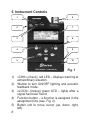
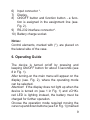
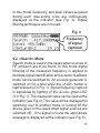
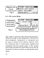
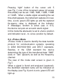
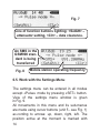
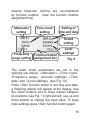
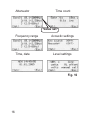
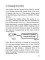
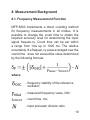
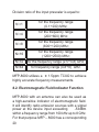
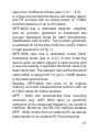
HANDHELD FREQUENCY
AND POWER METER
MFP-8000
USER MANUAL
CERTIFICATE
© TS-Market
Contents
1. General..................................................3
2. Warning.................................................5
3. Delivery Set...........................................6
4. Specifications.......................................7
5. Instrument Controls.............................8
6. Operating Guide...................................9
6.1. «Panorama» Mode......................10
6.2. «Search» Mode........................... 11
6.3. «Fix Level» Mode........................12
6.4. «Pulse» Mode..............................13
6.5. Work with the Settings Menu.......14
7. Charging the battery..........................17
8. Measurement Background................19
8.1. Frequency Measurement.............19
8.2. Electromagnetic Field Indicator...20
8.3. Operating Failures.......................22
9. Manufacturer`s Warranty...................22
10. Importer:............................................23
10. Claims Data.......................................23
1. General
The present User Manual is for a handheld
frequency and power meter MFP-8000 describing
its prin-ciples of operation.
MFP-8000 can be used to measure frequency
and power of radio signals in a wide range of
develop-ment, diagnostic, adjustment and search
applications related to radio devices.
Specialists are familiar with manual field indicators
of MFP series used for these purposes with an
option of measuring frequency. These handheld
devices have worked reliably during many years,
the latest from them is MFP-3.
The handheld frequency and power meter
MFP-8000, developed on the basis of the latest
advances in the RF components and technology
and vast engineering and operating experience
incorporates the best properties and features of
MFP instruments.
MFP-8000 can detect any sources of radio emission
within the frequency range from 100 kHz up to
8GHz featuring sensitivity of -53dBm with a typical
S/N ration of 5dB. That means that a transmitting
device with an output power of +7dBm (5mW)
coupled to a matched 1/4 wavelength antenna can
be easily detected from the distance of up to 8m.
MFP-8000 provides the user with a wealth of
functions:
• It can determine frequency of the input signal
within a frequency range from 100 kHz to 8
GHz.
• It can measure power of the input signal within
a level range from -50dBm to +30dBm.
• It can identify in the input signal characteristic features of the data transfer protocol for
different communication standards (GSM
900/1800/1900, DECT), e.g. for GSM it can
determine “SMS” and “Talk” operating modes,
as well as the frequency channel.
• It can automatically tune radio receivers and
spectrum analyzers to the measured signal
frequency via a built-in interface (option, ordered separately).
• It can use its built-in memory, clock and calendar functions to protocol and store measurement re-sults.
• It can be integrated into automated systems of
radio monitoring via a serial interface.
• It can utilize acoustic feedback mode during
search work.
• It supports surveillance mode when it responds to signals with a power level exceed
ing a specified threshold.
MFP-8000 has the following features:
• 30dB input attenuator adjusted in 10dB steps.
• Count time selection.
• Input frequency range selection.
• User level correction setting.
• Battery charge/discharge control.
• Real-time clock and calendar.
• Built-in light and acoustic indication.
• RS-232 interface.
2. Warning
Attention! The manufacturer reserves the right
to make small design changes not decreasing
(but im-proving) its operating specifications. In
this case the present User manual may not fully
correspond to the modification of the device you
have. To get comprehensive and the most upto-date information, please, download the latest
versions of the User Manual at the manufacturer`s
web-site www.elvira.ru.
Before turning the device on study the present
Manual thoroughly, and further strictly follow its requirements.
It is strictly forbidden to disassemble the device
independently and to connect to it devices not
covered in the present Manual.
Warranty and after-warranty service of the device
is provided by the manufacturer only if the present
manual is submitted and the Certificate is properly
filled in, and there is no damage of sealing.
If there are mechanical damages in the device,
if the device has been operated in a chemically
aggressive environment, if water, dirt and insects
are found inside the device, or if a user violates the
operating instructions, sealing and requirements
of this Manual the warranty liabilities become
ineffective.
3. Delivery Set
№
1
2
3
4
5
6
7
8
9
Name, type
MFP-8000
Antenna А-1
Antenna А-2
N-BNC adapter
RS-232 interface cable
Charger
User Manual
Certificate
Package box
Number, pcs.
1
1
1
1
1
1
1
1
1
4. Specifications
•
•
•
•
Frequency range: 100 kHz…8 GHz.
Maximum safe input level: +30dBm (1W).
Input impedance: 50 Ohm.
Dynamic range of power level measurement:
90dB, (-60dBm…+ 30dBm).
• Accuracy of power level measurement:
± 0.5dB.
• Sensitivity for frequency measurement:
≤-45dBm (-45dBm 1.26mV) for the
frequency range (300¸6000) MHz, ≤12,68mV
(-25dBm) for the ranges (0.1¸ 0.3) MHz
and (6000¸8000) MHz.
• Typical sensitivity of power measurement:
≤ -53dBm (S/N >5dB).
•13MHz reference oscillator: ± 2.5ppm
(-30 +80 °C), ±1,5ppm (+25 °C).
• VSWR ≤1,5.
• Operating temperature range: from 0°C
up to +50 °C.
• Power supply: a built-in Li-Ion battery
3.6 W/1.95 А/h.
• Average current consumption: ≤ 250 mA.
• Input connector: N-type (female).
• Dimensions: 115mm х 70mm х 27mm.
5. Instrument Controls
1
6
2
7
3
8
4
9
5
10
Fig. 1
1) «CHK» (check) red LED – displays warning at
extraordinary situation.
2) *Button to turn ON/OFF lighting and acoustic
feedback mode.
3) «LOCK» (lockup) green LED – lights after a
signal has been found.
4) Function button – a function is assigned in the
assignment line (see. Fig. 2).
5) Button unit to move cursor (up, down, right,
left).
6) Input connector *.
7) Display.
8) ON/OFF button and function button - a function is assigned in the assignment line (see.
Fig. 2).
9) RS-232 interface connector*.
10) Battery charge socket.
Notes:
Control elements, marked with (*), are placed on
the lateral side of the case.
6. Operating Guide
The device is turned on/off by pressing and
keeping ON/OFF button for about 3 seconds (see
8 in Fig. 1).
After turning-on the main menu will appear on the
display (see. Fig. 2), where the operating mode
can be selected.
Attention! If the display does not light up when the
device is turned on (see 1 in Fig. 1) and «CHK»
red LED is lighting instead, the battery must be
charged for further operation.
Choose the operation mode required moving the
cursor up and down buttons (see 5 in Fig. 1) (marked
with reverse brackets). A mode is activated after
pressing button 4 (see Fig. 1) marked at the display
in the function assignment line.
Function
assignment
line
Fig. 2
6.1. «Panorama» Mode
Attenuator
Frequency
counter line
Power
meter
line
Function
assigned to
the button
Time count
Battery
state
Frequency
range
indicator
Current time
Fig. 3
Panorama mode can be used in all cases of
measuring frequency and power of an electric
signal applied to the instrument’s input connector.
10
In this mode frequency and level values acquired
during each mea-suring cycle are continuously
displayed at the indicator (see Fig. 3). Digital
filtering techniques are not used.
Fig. 4
Frequency
of signal
captured
6.2. «Search» Mode
Search mode is used in the cases when sources of
RF emission are to be found. In this mode digital
fil-tering of the measured frequency is applied to
facilitate signal identification and acoustic feedback
mode can be switched on. An acoustic generator is
switched on for a time while the «AUD» button is
kept pressed (2 in Fig. 1). Signal frequency capture
is signalized by lighting of the «Lock» green LED
(3 in Fig. 1). The measured value can be read at the
indicator (see Fig.4). This value will be displayed till
switching over to another mode or turning off the
device (even in the cases when signal sources are
switched off). If no signal is found the appropriate
message is displayed at the indicator (see Fig. 5).
11
Signal is not
found
Fig. 5
6.3. «Fix Level» Mode
Threshold
mark at the
level scale
Fig. 6
Excess threshold relative to
the background level
This mode is used for radio monitoring purposes.
When this mode is first switched on, the level of
elec-tromagnetic background is measured and
its value is stored to the internal memory. Then
the measured level is continuously updated and
compared with the stored value. If the current
level value exceeds the memorized one by the set
threshold, the device outputs an appropriate alarm
signal.
12
Pressing “right” button of the cursor unit 5
(see Fig. 1) one of five increment values (of excess
thre-sholds) can be set: +3dB, +6dB, +12dB, +18dB
or +24dB. When a stable signal exceeding the set
thre-shold appears, the instrument captures it in realtime, «Lock» green LED lights up and the captured
fre-quency value is displayed at the indicator.
If «Message» function is active (see cl. 6.5.)
the device out-puts an acoustic alarm signal.
In this mode the attenuator is set to «Auto» position
and indication level - to «Line» position by default.
6.4. «Pulse» Mode
«Pulse» mode is used to identify the data transfer
protocol for communication systems operating
in GSM 900/1800/1900 and DECT standards.
Besides, in the GSM standard the device
determines the type of the transferred data: “SMS”
(text) or “Talk” (speech) as well as the frequency
channel.
The view of this mode start screen is given in
Fig.7.
When a signal is found and analyzed (captured),
the identified standard name will be indicated at
the display (see Fig. 8) and «Lock» green LED will
light up.
13
Fig. 7
Line of function buttons lighting: <SetAtt> –
attenuator setting, <Clr> – data clearance.
An SMS in the
GSM900 standard is being
transferred
Fig. 8
Mobile station operating frequency
6.5. Work with the Settings Menu
The settings menu can be entered in all modes
except «Pulse» mode by pressing «SET» button.
View of the settings menu window is given
in Fig. 9.
All movements in this menu and its sub-menus
are made using cursor buttons (unit 5 - see Fig. 1)
ac-cording to arrows: up, down, right, left. The
position active at the moment is marked with
14
reverse brack-ets. Actions are accomplished
by function buttons (view the function buttons
assignment line).
Attenuator
setting
Time count
setting
Setting of
time and date
Sound
setting
Frequency Function button
range setting assignment line
Level
settings
Fig. 9
The exact mode parameters are set in the
opening sub-menus: «Attenuator», «Time count»,
«Frequency range», «Acoustic settings», «Time,
date» and «Level settings» (see Fig. 10).
Press <Set> function button to set time and date,
a flickering marker will appear at the display. Use
the cursor buttons unit to move marker between
its positions (see Fig. 1) right and left, use up and
down buttons to change the input value. To keep
input settings press <Set> function button again.
15
Attenuator Time count
Value set
Frequency range
Time, date
Acoustic settings
Level settings
Fig. 10
16
7. Charging the battery
The charge indicator placed in the right top corner
of the display shows the charge level of the builtin battery (see Fig. 11). The battery charge level
is approximately proportional to number of black
sectors.
To charge the battery when the device is on,
connect a charger included with the instrument to
the «CHG» socket (10 in Fig. 1), then to the mains.
While the battery is being charged, the number of
black sectors will increase. When charging is over
all sectors are black, the device goes on operating.
The bat-tery charging time in this case is about
seven hours.
Indicator of battery
charge/discharge
Fig. 11
If the device is off when a charger is connected to
it, it will automatically switch over to the «QUICK
CHARGE» mode (a corresponding inscription
appears on the display). Charging time of a
discharged battery is about 3 hours in this mode.
When the battery charging is over, the device turns
off automati-cally.
17
Attention! If the battery is discharged greatly, then
a display does not switch on immediately. First
«CHK» red LED lights, then the device switches
over to «QUICK CHARGE» mode after some
time (after the battery voltage achieves a certain
value), and charging process goes on as described
above.
Please note that the lifetime of a built-in battery is
limited: in 2 years from the date of the device manufacture it stops to provide its nominal capacity, and
in 5 years it is subject to obligatory replacement
re-gardless of its working state.
The battery capacity value can be implicitly
estimated by the charging time of a fully
discharged battery. Decrease of charging time of
a fully discharged battery by two times compared
to the initial condition is a signal for a battery
replacement.
Replacement of the battery is made by the
manufacturer (ELVIRA Production Company Ltd.).
18
8. Measurement Background
8.1. Frequency Measurement Function
MFP-8000 implements a direct counting method
for frequency measurements in all modes. It is
possible to change the count time to obtain the
required accuracy level for determining the input
signal frequen-cy. Count time can be set within
a range from 1ms up to 1000 ms. The relative
uncertainty of a frequen-cy value averaged over the
count time does not exceed the value determined
by the following formula:
where:
- frequency stability of the reference
oscillator;
- measured frequency value, kHz;
- count time, ms;
- input prescaler division ratio.
19
Division ratio of the input prescaler is equal to:
N =1
for the frequency range
(0.1÷200) MHz;
N =4
for the frequency range
(200÷600) MHz;
N =8
for the frequency range
(600÷1200) MHz;
N=16
for the frequency range
(1200÷2500) MHz;
N=32
for the frequency range (2.5÷4,8) GHz;
N=64
for frequency range (4.8÷8) GHz.
MFP-8000 utilizes a ± 1.5ppm TCXO to achieve
highly accurate frequency measurements.
8.2. Electromagnetic Field Indicator Function
MFР-8000 with an antenna can also be used as
a high-sensitive indicator of electromagnetic field.
It will identify radio emission sources with a signal
power at the device input exceeding
-53dBm
within a frequency range from 100 kHz up to 8 GHz.
For that purpose MFР – 8000 has a corresponding
20
selec-tion of different modes (see cl. 6.1…6.5).
In a free environment the device will reliably detect
any RF sources with an output power of +7dBm
from the distance of up to 20 meters.
MFP-8000 has a dedicated detector, amplifier
and an acoustic generator to implement the
acoustic feed-back mode for radio microphones
identification and location. The acoustic generator
is switched on for the time while the «AUD» button
is kept pressed (2 in Fig. 1).
MFР–8000 also has a dedicated «close field»
monitoring mode (see cl. 6.3.). In this mode the
device gives an alarm signal if a radio source with
a level exceeding a specified threshold value has
been identi-fied. The operator can set the threshold
value within a range from +3 up to +24dB relative
to the back-ground level.
Besides, MFP-8000 can store to its internal
memory an entire measurements protocol with up
to 1000 values for future analysis.
MFР - 8000 can automatically tune scanning
receivers (e.g. AOR 8000 type) or spectrum
analyzers to the measured frequency via a built-in
interface. Moreover, the RS-232 interface enables
MFР - 8000 control from an external PC as well as
data transfer to an external PC for processing.
21
8.3. Operating Failures
Electrostatic discharge, high power electromagnetic
pulses and other extraordinary effects may negatively impact on the device correct operation.
Under certain conditions it may even “hang-up”
and not respond to the control buttons. In this
case try to use the «reset» button first. For that
purpose carefully press the “reset” button with a
thin object (e.g. with an unbent clip) through a hole
placed on the back cover of the device near the
acoustic generator grating. After that the device
should reboot and return to the main menu. If it
nevertheless does not, contact the manufacturer.
9. Manufacturer`s Warranty
The manufacturer guarantees device operating
capability provided that the customer follows
operation, transportation and storage conditions
stated in the present User Manual.
Warranty period for the device is 18 months from
the acceptance date. The acceptance date must
be fixed in the present User Manual.
If the device fails during warranty period provided
that a customer follows operation, transportation
and storage conditions stated in the present User
Manual, the manufacturer will remove the defect
free of charge and take measures to exclude such
defects in future.
22
10. Importer:
TS-Market Ltd.
Building 10-1 Sosnovaya Alleya, Zelenograd,
Moscow, the Russian Federation, 124489.
Tel.: +7(495) 638-8800
Fax.: +7 (499) 940-9575
www.ts-market.com
[email protected]
10. Claims Data
In case of package damage during transportation
claims are presented to the freight forwarder.
If the delivery set is not complete or the handheld
frequency and power meter MFP - 8000 is
damaged, provided that a package is not damaged,
an Act is made together with a representative of
the manufac-turer.
If a defect appears during the warranty period, a
customer is to send the handheld frequency and
power meter MFP - 8000 to the manufacturer with
an accompanying letter, stating the reason of the
claim.
All claims put in, their brief description and
measures taken are recorded in Table 1.
23
Claim
content
24
Reason,
measures
taken
Notes


![Defining Event Handlers [Backbase Manual]](http://vs1.manualzilla.com/store/data/005692904_1-d6f01c41c66ce6049d8fb6a78592ae1b-150x150.png)