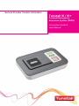
1
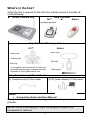
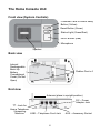
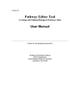
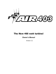
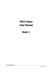
Service Provider Contact information Tunstall Vi / Vi+ Personal Emergency Response System (PERS) Connection Guide & User Manual Contents What’s in the box?......................................................................... 3 The Home Console Unit ................................................................ 4 Installation Advice ......................................................................... 5 How to install................................................................................................. 7 Using the PERS ............................................................................. 9 Making a Call to the Response Center ......................................................... 9 Canceling a Help Call ................................................................................... 9 Using the yellow Customer Care or Home Away button .............................. 9 Answering calls remotely via the portable Help Activator ............................. 9 Status Warnings & Voice Messages .......................................... 10 Telephone-Line Monitoring & Messages .................................................... 10 DC (electrical) Power Back-Up Monitoring & Messages ............................ 10 Home Console Unit Messages & Status Lights .......................................... 11 Help Activator Indicator Light ...................................................................... 11 Removing & Returning your System .......................................... 12 Disconnecting the system ........................................................................... 12 Help and Advice........................................................................... 13 False alarms ............................................................................................... 13 Troubleshooting .......................................................................................... 13 Cleaning ...................................................................................................... 13 Moisture ...................................................................................................... 13 Battery information ...................................................................................... 13 FCC Notices ................................................................................. 14 Technical Details ......................................................................... 16 Environmental ............................................................................................. 16 Standards .................................................................................................... 16 IMPORTANT NOTE: Calls to the Response Center and Customer Care or Home Away Help Line may be monitored and recorded for training and operational purposes, and to improve the quality of our service. 2 What’s in the box? When the box is opened for the first time, please ensure it includes all of the following: Home Console Unit Help Activator iVi™ or Amie+ intelligent pendant Help Activator Wearing options iVi™ Amie+ Neck cord Neck cord Clothing clip Belt clip Belt clip Your supplier will provide the iVi with your preferred wearing option, please read the separate iVi user guide before use. Wrist strap Telephone Line and Power Cords ⓐ Telephone cord (10 foot cable) ⓑ DC power adaptor (10 foot cable) Guide: Connection Guide and User Manual If any of the above items are missing, please contact your service provider. NOTE: Retain all packaging in case the equipment needs to be transported or returned. 3 The Home Console Unit Front view (System Controls) Customer Care or Home Away Button (Yellow) Reset Button (Green) Status Light (Green/Red) HELP Button (Red) Microphone Speaker Back view Internal Rechargeable Back-Up Battery Compartment Cover (Do Not Open) Rubber Feet x 4 End view Antenna (place in upright position) DC – Power Adaptor Jack - Jack for Home Telephone / Answering LINE – Telephone Cord Jack Machine 4 AUX – Accessory Socket Installation Advice The initial set-up of your PERS is important in providing a safe and reliable service. Please carefully read the “Do’s and Don’ts” section prior to connecting your system. If you have any questions, please contact your Service Provider. Do’s Do: Place the Home Console Unit on a flat, sturdy, non-metallic surface near a modular phone jack and electrical power outlet that is powered at all times. Do: Place the Home Console Unit in a central location in the home to optimize voice and Help Activator range. Do: If you have a cordless telephone, attach the base station directly to the jack labeled on the rear of the Home Console Unit Do: Update your information with the Response Center if your household or responder information changes or you move to a new or secondary home. Do: Contact your Service Provider if the Red or Orange LED on your Help Activator flashes or does not illuminate when pressed or if you lose any part of your system. Do: Regularly test the system using the Help Activator to ensure you are comfortable with the service and accustomed to speaking with the Response Center. Don’ts Do not: Expose the Home Console Unit to water or other liquids. Do not: Connect cables other than those supplied with the unit. Do not: Place your Home Console Unit next to something that makes a lot of noise, such as a television, radio, air conditioner or washing machine. Do not: Put your Home Console Unit next to your stove or close to any other heat source. Do not: Put your Home Console Unit in a place where it will get damp, such as a bathroom, or near house plants that are sprayed at any time. Do not: Place the Home Console Unit close to any large metal objects, such as refrigerators or microwave ovens, as large pieces of metal can inhibit the range of the Help Activator. Do not: Place items on top of the Home Console Unit. Do not: Place your Home Console Unit closer than four feet to something that may emit electromagnetic interference, such as a cordless telephone, CD, video player or personal computer, as this may inhibit the range of your Help Activator. 5 If you have broadband/cable phone service The home console unit contains a built in DSL filter so it is compatible with broadband/cable telephone phone service. A separate DSL filter is not required. WARNING IF YOU HAVE A BROADBAND/CABLE PHONE SERVICE AND THERE IS A POWER FAILURE If there is a power failure to your home, your telephone service will become disabled unless you have a back-up power supply connected to your home or modem. Although the PERS unit does have an internal back-up battery, it will be unable to transmit a signal to the Response Center because there is no dial tone. Important safety notice – seize line wiring information If you have more than one telephone in your home sharing the same telephone number/line as the Home Console Unit and one of those phone extensions is in use or off the hook, the system will not operate without the installation of an RJ31x seize line telephone jack. Contact your telephone service carrier to arrange for the installation of this phone jack. The system is to be wired in accordance with the following diagram. A separate line cord (part number XD3605044) is required to connect to an RJ31x jack. 6 How to install Step 1 - Connecting the power and telephone line cords Step A – Plug the supplied telephone cord ⓐ into the jack on the rear of Home Console Unit labeled LINE. Disconnect your existing telephone line from the telephone jack and insert the one supplied with the system into the telephone wall jack. Step B – Plug the telephone into the jack on the Home Console Unit labeled . If you have an answering machine, plug the answering machine into the rear of the console first and then plug the telephone into the answering machine. Step C – Plug the DC power adaptor ⓑ into the jack on the Home Console labeled DC and then connect a power outlet that is always on (not controlled by a wall switch or timer). Step D – Stand the antenna upright. 7 Step 2 – Initial System Test Press the button on the Help Activator. The two-way voice Home Console Unit will beep and transmit a signal to the Response Center. A Response Center operator will speak with you over the Home Console Unit to activate the service, verify personal and responder information and ensure the system is working properly. If you have more than one Help Activator, please be sure to send a signal to the Response Center by pressing the button of each activator. IMPORTANT NOTE: The operation of your system is dependent upon compatible phone service. A change in telephone service after proper installation may render the system inoperative. If the phone service is changed or modified, the subscriber must verify the system compatibility by successfully activating the system with the Response Center. If the signal is not received by the Response Center, the phone service may not be compatible and the system will not operate as intended. Step 3 – Help Activator Range Test The range of all programmed help activators can be tested without calling the Response Center. The range of help activator(s) should be tested upon installation or relocation of the Home Console Unit to confirm coverage around your home. To put the Home Console Unit into walk/range test mode, follow these simple steps; 1. 2. 3. Press and hold the GREEN RESET button on the home console unit until it beeps. After releasing the button, the unit will announce “PROGRAMMING MODE”. Test the help activator by pressing the button. If you are in range, the Home Console Unit will announce “PERSONAL TRIGGER” or “FALL DETECTOR” depending on the help activator supplier to you. Test in different locations of your home. If you do not hear “PERSONAL TRIGGER” after pressing the help activator, you are out of range. Try to find a more central location for the Home Console Unit to allow for improved activator range coverage. The Home Console Unit will automatically exit range test mode after 2 minutes. To manually exit the range test mode, press the GREEN RESET button. IMPORTANT NOTE: It is important to test the help activator in all the areas of your home, including the bathroom, basement and garage, as environmental conditions such as furnishings or building structure may affect the range. An emergency call will NOT be initiated if the help activator is pressed and it is out of range of the Home Console Unit. 8 Using the PERS Making a Call to the Response Center Press the button on the Help Activator or the red HELP button on the Home Console Unit. Canceling a Help Call If you accidentally press the Help Activator button, immediately press the GREEN RESET button on the Home Console Unit to cancel the signal. Using the yellow Customer Care or Home Away button The Home Console Unit is equipped with a yellow Customer Care or Home Away button. The availability of Customer Care or Home Away is determined by your Service Provider. If the Customer Care or Home Away is enabled, you will be provided with specific instructions on its operation. If Customer Care or Home Awayis not enabled, pressing the yellow button will provide no functionality. Answering calls remotely via the portable Help Activator The Help Activator can be used to answer incoming telephone calls remotely by pressing its button while the Home Console Unit or connected telephone is ringing. When pressed, the Home Console Unit will answer the call and allow you to communicate with the caller hands free via the Home Console Unit. To revert to handset mode, just pick up the handset of the connected telephone. Replacing the handset will end the call. To end a hands free call, press the Help Activator button again. 9 Status Warnings & Voice Messages Telephone-Line Monitoring & Messages If the telephone line goes out of service, becomes inoperable or cord becomes disconnected from the jack or console, the Home Console Unit will announce ‘WARNING – the telephone line is disconnected’ after 1 minute and the red status light will flash once every second. This warning will be repeated every 30 seconds until the telephone service is restored. If you hear this voice message, check to make sure that the telephone line and electrical power connections to the Home Console Unit and wall are secure. If the message persists, the following issues may be the cause of the problem; 1. 2. 3. Telephone line may be out-of-service. The telephone line connection to your home may be disconnected or compromised. If you have broadband or cable phone service and electrical power goes out, there will be no dial tone unless you have an un-interruptible power supply connected to the modem. If all connections are secure and the warnings continue, press the GREEN RESET button to silence the warning. Please note that during this condition, the system will be unable to send a signal to the Response Center. If the warning continues after power and phone service is restored, contact your local telephone line company or call your Service Provider. DC (electrical) Power Back-Up Monitoring & Messages If a DC power failure occurs, the Home Console Unit will continue to work using its backup battery, however, as a warning the red help button will flash once every 4 seconds (see section – Home Console Unit Messages on the next page). The unit will also announce ‘WARNING – there is no electrical power’. This warning is repeated every 5 minutes. To silence the warning press the GREEN RESET button. If the power failure lasts for more than 1 hour, during the next hour the unit will automatically transmit a signal to the Response Center. A call will then be raised periodically to the Response Center until the electrical power is 10 restored. The battery provides approximately 30 hours of backup battery to allow you to call the Response Center during a power outage. If you have Broadband/Cable phone service, the PERS may be unable to send a signal due no phone line service. Home Console Unit Messages & Status Lights Customer Care/Home Away Button (Yellow) On Off Status LED (Green/Red) Green LED on Red LED flashing (1 every 4 seconds) CUSTOMER CARE Home console unit status To be determined by your Service Provider To be determined by your Service Provider Home console unit status Normal mode Low battery Red LED flashing (1 every second) Telephone line disconnected Red/Green flashing Radio blocking detected. Check that the home unit is not close to any other electrical devices such as a computer, television, fan, mobile phone. If so, turn-off or move the equipment away from the home unit and check if this stops the warning. Alarm Button (Red) Home console unit status On Normal mode Flashing (1 every 4 seconds) Flashing (1 every second) Normal mode running on battery RESET HELP Alarm mode Help Activator Indicator Light Indicator lights Light off Light on when pressed Light flashing red after the button is pressed Message Description Normal mode When the button is pressed, the lights will steadily illuminate for a short period The battery is low. Contact your Service Provider. 11 Light flashing orange No light when pressed Fall Detector error detected. Contact your Service Provider immediately. The internal battery is fully depleted. The button will not work. Contact your Service Provider. Removing & Returning your System Please contact your Service Provider before attempting to remove or return your system. Prior to disconnecting the System, please inform the Response Center by either activating the Home Console Unit or by calling. Disconnecting the system 1. Remove all wires from the rear of the Home Console Unit including the telephone line and power adaptor. To remove cords, press down gently on each clip and pull the cord from both the ‘DC’ and ‘LINE’ jacks. Also remove the cord connected to telephone from the jack labeled. After 1 minute of being disconnected from both the power outlet and telephone line, the Home Console Unit will automatically power down ready for packaging. 2. Locate the original box and enclose the following items: 3. Home Console Unit Help Activator(s) Neck Cord Wrist Strap Belt Clip Telephone Line Cord A/C Power Adaptor After you have properly packed up all equipment in the original box, please contact your Service Provider for instruction on the proper method for returning your equipment. IMPORTANT NOTE: If any equipment is not returned, the subscriber and/or billing party will be responsible for lost equipment charges in accordance with the Service Agreement. 12 Help and Advice False alarms If you accidentally activate a help call by inadvertently pressing your help activator or the red HELP button on the home console unit, please do not worry. The Response Center operator is always happy to talk with you. Troubleshooting If your home console unit does not work: Ensure the telephone cord is plugged into the main telephone jack – see page 7. Ensure that the DC power adaptor is plugged into the unit and a nonswitched (always on) electrical outlet. Ensure that DC power supply is being supplied to the home console unit (the green LED light should be on). If the home console unit has a lit or flashing light, please see the Home Console Unit messages and status lights section. Cleaning Dust the home console unit with a soft cloth which can be lightly moistened with a gentle detergent if required. Ensure that no moisture goes through the speaker grill. The Help Activator can also be cleaned in the same manner. Moisture Don’t position your home console unit where it may come into contact with water or moisture. Help activators are waterproof (to IP67 standard) up to 3 feet water depth. They can be worn in the shower or bath however they should not be submerged for more than 30 minutes. Battery information Please contact your Service Provider if batteries need to be replaced. Do not open the battery compartment or attempt to replace the battery. 13 FCC Notices Federal Communications Commission (FCC) notices This equipment complies with Part 68 of the FCC rules and the requirements adopted by the ACTA. On the exterior of the cabinet of this equipment is a label that contains, among other information, a product identifier in the format US:G2XAL03B57004. If requested, this number must be provided to the telephone company. • • • • • ACTA Registration Number: Ringer Equivalence Number (REN): Facility Interface Code (FIC): Service Order Code (SOC): USOC Jack Type: US: G2XAL03B57004 0.3 02LS2 9.0F RJ11C Universal Service order Code (USOC): RJ11C A FCC compliant telephone cord and modular plug is provided with this equipment. This equipment is designed to be connected to the telephone network or premises wiring using a compatible modular jack that is Part 68 compliant. See Installation Instructions for details. Ringer Equivalence Number (REN): 0.3 The REN is used to determine the quantity of devices that may be connected to the telephone line. Excessive RENs on the telephone line may result in the devices not ringing in response to an incoming call. Typically, the sum of RENs should not exceed five (5.0). To be certain of the number of devices that may be connected to a line (as determined by the total RENs) contact the local telephone company. If this equipment, causes harm to the telephone network, the telephone company will notify you in advance that temporary discontinuance of service may be required. But if advance notice isn't practical, the telephone company will notify the customer as soon as possible. Also, you will be advised of your right to file a complaint with the FCC if you believe it is necessary. The telephone company may make changes to its facilities, equipment, operations or procedures that could affect the operation of the equipment. If this happens, the telephone company will provide advance notice so you can make the necessary modifications to maintain uninterrupted service. This equipment (home console unit) contains no user serviceable parts. If trouble is experienced with this equipment, for repair or warranty information please call your service provider. If the equipment is causing harm to the telephone network, the telephone company may request that you disconnect the equipment until the problem is resolved. 14 Connection to party line service is subject to state tariffs. Contact the state public utility commission, public service commission or corporation commission for information. If your home has specially wired alarm equipment connected to the telephone line, ensure the installation of this equipment (home base) does not disable your alarm equipment. If you have questions about what will disable alarm equipment, consult your telephone company or a qualified installer. Alarm dialing equipment must be able to seize the telephone line and place a call in an emergency situation. It must be able to do this even if other equipment (telephone, answering system, computer modem, etc.) already has the telephone line in use. To do so, alarm dialing equipment must be connected to a properly installed RJ31X jack that is electrically in series with and ahead of all other equipment attached to the same telephone line. Proper installation is depicted in the following figure. If you have any questions concerning these instructions, you should consult your telephone company or a qualified installer about installing the RJ31X jack and alarm dialing equipment for you. This equipment has been tested and found to comply with the limits for a Class B digital device, pursuant to part 15 of the FCC Rules. These limits are designed to provide reasonable protection against harmful interference in a residential installation. This equipment generates, uses and can radiate radio frequency energy and, if not installed and used in accordance with the instructions, may cause harmful interference to radio communications. However, there is no guarantee that interference will not occur in a particular installation. If this equipment does cause harmful interference to radio or television reception, which can be determined by turning the equipment off and on, the user is encouraged to try to correct the interference by one or more of the following measures: Reorient or relocate the receiving antenna. Increase the separation between the equipment and receiver. Connect the equipment into an outlet on a circuit different from that to which the receiver is connected. Consult Customer Care or contact your Service Provider. Personal Help Activator (Part Number 63604/01, 63604/12, 66004/09) FCC ID: G2X-63604A, FCC ID: G2X-6360412, FCC ID: G2X-66004V This Device complies with Part 15 of the FCC Rules. Operation is subject to the following two conditions: (1) This device may not cause harmful interference, and (2) This device must accept any interference received, including interference that may cause undesired operation. Warning: Changes or modifications to this unit not expressly approved by the party responsible for compliance could void the user’s authority to operate the equipment. 15 Technical Details Weight: Dimensions: DC power: Stand-by battery: Back-up time: Radio frequency: Radio range: REN: External connections: 1.26lb (575g) 7.28” x 4.80” x 1.61” (185 x 122 x 41mm) (WxLxD) 110 to 120v DC power receptacle 1200mAhr capacity (continually internally recharged) 30 hours of stand-by operation with one 30 minute alarm call (minimum expected at date of purchase and when fully charged) 312.00MHz 390ft (120m) in free space 0.3 10ft (3m) telephone line cord with type RJ11 plug, DC power adaptor with 10ft (3m) cable An optional RJ31x line cord 10ft (3m) part number XD3605044A is available – Contact Customer Care 1-877903-5111 Environmental Temperature: Humidity: Operating temperature (to perform to full specification) = 0°C to 45°C, storage = -10°C to 50°C Operating relative humidity (non condensing to perform to full specification) = 0 to 80%, storage relative humidity (non condensing) = 0 to 93% Standards US: Canadian: FCC CFR47 part 15, FCC CFR47 part 68, ETL/UL1637, ETL/UL1635 CETL/CSA22.2 No 205, RSS210 Design and Manufacture: ISO9001:2008 303 Tunstall Americas 100 Freight Street Pawtucket RI 02860 800-286-2622 MD5 Tunstall Canada, Inc 111 Zenway Blvd. Unit 6A Woodbridge, Ontario Canada L4H 3H9 800-892-2205 Tunstall Americas Response Center and Customer Care 1-877-903-5111 tunstall.com Our policy of continual development means that product specification and appearance may change without notice. © 2015 Tunstall Healthcare Group Ltd. ® TUNSTALL is a registered trademark. Manufactured by Tunstall Healthcare Group, Whitley Lodge, Whitley Bridge, Yorkshire DN14 0HR Tel: +44 1977 661234 Fax: +44 1977 662450 Email: [email protected] D5707038A