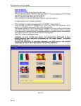
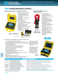
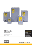
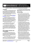
1
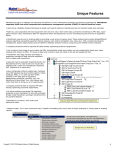
SD3 Diagnostics System User Manual
4. BASIC SD3NET PC Software
Page 60
SD3 Diagnostics System User Manual
4.1 Introduction
SD3NET PC is the Basic System on the PC used to manage the SD3 diagnostics system.
The program has the following main functions:
• Install diagnostics programs (SD3 and SD2);
• Download ECU software from PC to SD3;
• Update SD3 Operating System
• Analyze and process data acquired by the SD3;
• General management of the SD3 (time);
• Run PC SD3 and SD2 diagnostics software.
To perform any operation on the SD3 (except running software on the SD2 PC), you must turn on the Tester,
enter the "Start PC Communications" menu from the Main tester Menu and, depending on the
communications mode selected, make your connection.
• Serial: Cable connecting the Tester to one of the free serial RS232C lines on the PC.
• USB: Cable connecting the Tester to one of the free USB port lines on the PC.
• Ethernet: Crossover cable connecting the Tester to the PC if it is a 1-1 connection; or cable
connecting the Tester to the corporate network.
• Wireless: Insert the special Wireless card into SD3 the Tester
For a short description of the cables see paragraph 1.2.
The main screen is shown in fig. 4.1.1.
Fig. 4.1.1
Page 61
SD3 Diagnostics System User Manual
4.2 Update Menu
This menu is used to update the software on the SD3 Tester and to install/update the diagnostics
software on the PC (including the basic SD3NET PC software).
Fig. 4.2.1
Page 62
SD3 Diagnostics System User Manual
4.2.1 Update ECU Software
This option can be selected by clicking on the tool bar button shown on the left.
This menu allows you to load the SD3 diagnostics software available on CD into both the SD3 and SD2 (new
release). To load a program, insert the CD into the PC, select "Update ECU Software" and hook up the
Tester to the PC in "Start PC Communications" mode; the window shown in fig. 4.2.2 appears.
Fig. 4.2.2
To the centre-left, select the CD and/or directory where the installation files are located. The PC will display
the list of diagnostics programs available on the CD on the centre-right of the screen. Select the programs
you wish to load into the Tester. This can be done as follows:
• By clicking on "Select All", to select all the diagnostics programs on the CD;
• By highlighting a particular program with the mouse pointer and clicking on "Select one";
• By dragging a program from the centre-right panel to the bottom of the screen.
The selected programs appear in the bottom part of the window. If you make an erroneous selection, either
close the entire window and start again by selecting Update "ECU Software", or just click on "Deselect All".
To start the load, press "Transfer".
The PC first checks the Tester to see whether an upgrade has already been loaded in a different language
from the one currently selected. In this case it issues a warning. You can continue with the load procedure,
but the diagnostics software may be in different languages on the Tester or the same program may present
different messages in different languages.
Page 63
SD3 Diagnostics System User Manual
4.2.2 PC Update
This option can be selected by clicking on the tool bar button shown on the left.
This menu lets you install/update the diagnostics software on the PC of the SD2/SD1 porting, the basic
SD3NET software included.
To update, insert the CD into the PC, select "Update" and the window shown in figure 4.2.3 appears.
Fig.4.2.3
On the left, select the CD and/or directory where the installation files are located. The PC will display the list
of diagnostics programs available on the CD on the centre-right of the screen. Select the programs you wish
to load into the Tester. This can be done as follows:
• Click on "Select All", to select all the diagnostics programs on the middle list;
• Use the mouse to highlight a particular software;
You can deselect all by pressing the special "Deselect All" button.
To start the updating, press "Update".
If the update also includes the basic SD3NET PC software, a message will appear prompting you to
deactivate the basic software.
These files will only be updated when the program is rebooted.
4.2.3 Exit
Exits the SD3NET program
Page 64
SD3 Diagnostics System User Manual
4.3 PC Communication Menu
This option can also be selected by clicking on the button on the tool bar button to the side.
This menu lets you run the diagnostics software on the SD3 and SD2 PC to perform the main Test Cycles.
Use the mouse to select the desired diagnostics software and then press "RUN".
The native SD3 software (for Quattroporte M139 and 613 Scaglietti F137 vehicles) does not prompt for the
communications line (iso1, iso2, can etc..) because it is automatically selected by the tester.
For SD2 diagnostics software, a window appears where you can select the communications line (ISO1,
ISO2, RS232, CAN).
Fig. 4.3.1
Page 65
SD3 Diagnostics System User Manual
4.3.1 Running the software on the PC
This option can be selected by clicking on the tool bar button shown on the left.
Fig.4.3.2.
Page 66
SD3 Diagnostics System User Manual
In this menu you can run the Diagnostics software on the SD3 and SD2 PC to perform Test cycles.
The menu is shown in 4.3.2.
On the left side of the screen is a list of the diagnostics software developed for the SD3 diagnostics system;
on the right side you can run an application that lets you use the diagnostics software developed for the
Ferrari SD2 and Maserati SD2 system.
Running native SD3 Software
To run the native SD3 software you must set the SD3 Tester to "PC COMMUNICATIONS" mode
(Remember, the line and PC/ SD3 Tester communications setting must be aligned).
From the list, select the desired software and press "RUN", or double click on the name of the software. (see
chapter 4 for a description of the typical SD3 diagnostics software).
Run Ferrari/Maserati SD2 Software
To run the SD2 software you must set the SD3 Tester to "START SD2 EMULATOR COMMUNICATION"
mode
WARNING:
- THIS MODE USES THE SERIAL LINE.
- CONNECT THE HARNESS (SD3-CBL07) TO THE SD3 TESTER
Press "FERRARI SD2 EMULATION", or "MASERATI SD2 EMULATION" depending on which diagnostics
system you wish to run.
Once you have pressed one of the 2 buttons, access to the Basic SD3NET PC software will be denied until
the diagnostics have been completed. Then a "Basic SD2 Emulator Software " will be run similar to the one
indicated above for the SD2 diagnostics system.
Graphically the Basic Emulator Software is similar to the previous software, but the following functions are no
longer available:
- Update SD2 Tester
- Update
- Reset Tester Disc
- Select serial port
- Transfer Operating System
To actually run the diagnostics software, select "Run PC Software" from the Diagnostics Menu.
The software checks the SD3 Tester for the SD2 software, and displays a list of the systems for which
diagnostics can be run, indicating the presence of the software on the PC.
At this point you must
- Select a system from the list
- Select the Tester->ECU communications line (ISO1, ISO2, CAN, RS232)
- Run the Software.
Once system diagnostics has been completed, the unit automatically returns to the BASIC SD2 EMULATOR
software.
To complete the Emulation session, close the program; This operation restores control of the BASIC
SD3NET PC software.
For additional information on the basic SD2 CD software, see the user's manual contained in the CD for the
basic SD3NETPC software in the MANUALSD2 directory. (Remember that the chapters regarding Updating
the SD2 Tester and Operating System Transfer are meaningless for the emulator).
Page 67
SD3 Diagnostics System User Manual
Page 68
SD3 Diagnostics System User Manual
4.3.2 SD3 Tester Settings
This option can be selected by clicking on the tool bar button shown on the left.
Fig.4.3.3
This menu lets you select the type of communications channel to run SD3 tester diagnostics. The SD3 test
can communicate through: RS232 serial port, neworkt (TCP/IP through normal network interface card or
wireless) and USB port .
The SD3 is preset to perform diagnostics through a serial port (communication used in the SD2 tester, for
those familiar with that unit).
At the top of the window, there are some buttons you can use to determine the type of communication. The
particular setting of each communications channel is indicated just below each of these selection buttons.
In particular:
Serial: You can choose from up to 10 communications ports presented. Because of the limitations of
serial devices, the only way you can be sure that the communications port is actually connected to the tester
is to run specific requests For this reason, using the multiple choice button, you must select the desired port
(which must be connected to the SD3 tester).
The PC Desktop normally has two communications ports: COM1 and COM2. If there is only one, it is
normally COM1. For the portable units, the rules for PCs normally hold although they are more likely to have
several available ports. You can check serial port status of your operating system in the list of hardware
devices under "My computer".
LAN: Offers a list of testers; it was previously configured (see paragraph 4.5.1). For each of these, a
brief description and the network IP address is displayed. To select the desired tester, just select it from the
list (using the mouse or keyboard); this operation highlights it in the colours used by your operating system.
USB: Offers a list of testers. It must be detected when this window is opened. Each tester is
identified by a brief description and by the virtual USB port it is connected to. To select the desired tester,
just select it from the list (using the mouse or keyboard); this operation highlights it in the colours used by
your operating system.
Once you have made your choice, press Save and the modification goes into effect. If you do not wish to
make any modification to communications, press cancel.
Key functions:
SAVE: Sets communications and saves it for future access to this page.
CANCEL: Exits without making the modification
Page 69
SD3 Diagnostics System User Manual
4.4 Tester Data Menu
The Tester Data menu manages the data acquired and printed out with the ECU diagnostics
software.
Fig. 4.4.1
4.4.1 Print Menu
This option can be selected by clicking on the tool bar button shown on the left.
With the Tester connected in "Start PC Communications" mode, select "Print" and the window shown in
figure 4.5.1.1 appears. The upper box displays the print files performed with the connected SD3. The type
(Parameter, Error, ...), the date and time of the start and end of acquisition, the size of the file in bytes and
the name of the diagnosed ECU are reported for each file. Use the mouse to select/deselect the Tester files
(select/deselect all files using "Select All" and "Deselect All"). After selecting one or more files, transfer them
to the PC using "Copy Selection to PC", or delete them using "Delete Selection". The two operations
(transfer and delete) are independent of each other, hence transferring the files does not automatically
delete them from the Tester, and files can be deleted without being transferred to the PC.
Page 70
SD3 Diagnostics System User Manual
Fig. 4.4.2
Use "Update Tester List" to read the list of Tester files again. The lower field of the window in fig. 4.4.2
displays the printout/acquisition files previously transferred to the PC. Use the mouse to select/deselect the
PC files (you can also select all files using "Select All"). Selected files can be deleted using "Delete
Selection" or displayed on the PC using "View Selected Printouts". In this case, a window similar to the one
in fig. 4.4.3 appears.
To detect the files copied on your disk please check paragraph 4.4.3.
Page 71
SD3 Diagnostics System User Manual
Fig. 4.4.3
In this case two files have been selected. In the main box we can see the contents of one of them; to see the
contents of the other, click on the name of the file at the top of the window below the name of the window
itself. Use "Print Displayed Data" to print out the file in the main box; use "Print All and Vehicle Data" to print
out all the files in the window preceded by the data for one of the vehicles previously inserted from the
"Vehicle Data" menu (see par. 4.5.3).
4.4.2 Acquisition Menu
This option can be selected by clicking on the tool bar button shown on the left.
Select "Acquisition" with the Tester connected in "Start PC Communications" mode to call up the window in
figure 4.4.4. The box at the top displays the acquisition files performed by the SD3 connected. The type
(Parameter, Errors, ...), the date and time of the start and end of acquisition, the size of the file in bytes are
reported for each file. Use the mouse to select/deselect the Tester files (select/deselect all files using
"Select" and "Deselect" buttons). After selecting one or more files, transfer them to the PC using the "Copy"
button and/or delete them using "Delete". The two operations (transfer and delete) are independent of each
other, hence< transferring the files does not delete them from the Tester, and files can be deleted without
being transferred to the PC.
Page 72
SD3 Diagnostics System User Manual
Fig. 4.4.4
Use "Update" to read the list of Tester files again. The lower field of the window shown in fig. 4.4.3 displays
the acquisition files previously transferred to the PC. Use the mouse to select/deselect the PC files (select all
files using Select All). Selected files can be deleted using "Delete" or displayed on the PC using "Display". In
this case, a window similar to the one in fig. 4.4.4 appears.
To detect the files copied on your disk please check paragraph 4.4.3.
Page 73
SD3 Diagnostics System User Manual
Fig. . 4.4.5
The Simple Graph lets you display one single piece of Acquisition Data fig. 4.4.6
Fig. . 4.4.6
The graph with two Y-axes presents two Y-axes, the first on the left of the graph, the second on the right.
The two data refer their values to the two different axes (fig. 4.4.7).
Page 74
SD3 Diagnostics System User Manual
Fig. 4.4.7
Page 75
SD3 Diagnostics System User Manual
The graph with two Y-axes and several series presents two Y-axes, the first on the left of the graph, the
second on the right. The value of the first two pieces of data inserted refers to the two different axes. All the
other series inserted show only the trend of the data not represented by the axes; these values can only be
viewed using the cursor (Fig. . 4.4.8).
Fig. 4.4.8
Page 76
SD3 Diagnostics System User Manual
The graph with percentage Y-axis presents only one proportional Y-axis. It displays the trend for the series;
the maximum peak is 100% while the minimum peak 0%. If the data has a constant value for the entire
duration of the acquisition, the values are represented at 50%. (fig. 4.4.9).
Fig. 4.4.9
Page 77
SD3 Diagnostics System User Manual
After deciding what type of graph you wish to use, select the data to assign to the graph. Press FORWARD
in the window in fig. 4.4.10 and the parameters and error selection screen for the graph appears
The names of the files selected before entering the acquisition processing menu appear at the top. With the
mouse, click on the names or scroll with the arrows to view the data acquired in the various files. Once
selected from the list at the top, press the ADD button to assign the data to the graph data list. The first piece
of data selected is assigned to the first Y-axis, the second to the second Y-axis and the others are assigned
to the Additional Series. If you want to assign data directly to a specific axis, use the buttons ADD TO FIRST
Y-AXIS and ADD TO SECOND Y-AXIS. When data is assigned to the first or the second axis, its name, data
type and source file are placed in the rectangles next to the relevant button. The rectangles assume the color
for its data type: parameters are yellow, errors are red. If you had selected simple graph mode, the functions
relative to the second Y-axis and to the additional series are not available. If the graph with two Y-axes was
selected, the functions relative to the additional series are not available. If the graph with percentage axis
was selected, the functions relative to the Y-axes are not available and all the series will be arranged by
means of the ADD button in the list at the bottom.
Fig. 4.4.10
Page 78
SD3 Diagnostics System User Manual
SELECTION BAR
The selection bar is the bar located on the left side of the screen and contains buttons and scroll bars which
enable you to modify the aspect of the graph currently active on the bar itself. The active graphic window is
the one with the title bar in a different colour from the others and is in the foreground with respect to the
others. The contents of the selection bar will now be analyzed (Fig.4.4.11)
Fig. 4.4.11
NEW GRAPH Button Calls up the graph type selection screen. The selectable data always refers to the
selected acquisition files.
DATA TABLE Button Calls up the data table from which the graph is drawn. The first column indicates the
index of the sample acquired; followed by the column indicating the real time of he sample, and by the
column with the value the piece of data (be it error or parameter) assumed at the time on the same line (fig. .
4.4.12).
In the case where the maximum number of samples is less than 16000, only the buttons CONTINUE (closes
the table and returns to graphs) and PRINT (prints the table to paper) appear. If the number of samples is
greater, two further buttons appear (NEXT PAGE, PREVIOUS PAGE) which allow you to also view the data
after the first 16000.
Page 79
SD3 Diagnostics System User Manual
Fig. 4.4.12
CONFIGURE Button A window appears presenting the various options which may be set by the user. You
can select the line colours and size of the series of graphs (on screen and for printing). Press
PRESETTINGS to return to the configuration set at the time the program was installed.
Fig. 4.4.13
Page 80
SD3 Diagnostics System User Manual
X-AXIS
Fig. 4.4.14
The X-axis group allows you to modify the X-axis range.
This may be used to examine a short interval of a long acquisition.
With the Scroll bar, you can scroll through the graph toward the beginning or end of the data acquisition.
With the Graph Range bar you can select the quantity of acquisition to be viewed: if Graph Range is at
maximum value (displayed in the rectangle on the side), it means that the graph represents the data from the
moment in which acquisition started to the moment in which it ended. In this case scrolling is not possible.
Y-AXIS
Fig. 4.4.15
The Y-axis group allows you to modify the Y-axis range.
This may be used to view small variations, which a very wide range would not display.
With the scroll bar you can scroll through the graph toward the higher or lower range of the acquisition.
With the Min bar the value of the minimum range is modified (displayed in the rectangle).
With the Max bar the value of the maximum range is modified (displayed in the rectangle).
When the Min bar is at the minimum possible value and the Max bar at the maximum possible value,
scrolling is not possible.
Clicking on the rectangle containing the current minimum range value, this value is assumed as minimum
possible value for the range.
Clicking with the mouse on the rectangle containing the current maximum range value, this value is assumed
as maximum possible value for the range.
Page 81
SD3 Diagnostics System User Manual
CURSOR
Fig. 4.4.16
Moving the Cursor Scroll bar lets you view the values of all the samples acquired. The value is described by
the rectangle underneath; simultaneously a vertical line is displayed on the graph in correspondence to the
instant whose value is to be read. This operation can be carried out directly on the graph by pressing the
mouse button on the desired point.
SERIES Button. The series button opens a window where the information on the various series in the graph
may be viewed (fig. 4.4.17). This information is:
- the colour in which the series is displayed in the graph;
- the data name;
- the unit of measure. This information is not available for analogue-type parameters and for errors;
- the type of data: parameter or error;
- the ECU name. This information is not available if the acquisition software has not been installed on the
PC;
- the ECU software code;
- the date on which the acquisition was carried out;
- the acquisition start time;
- the acquisition end time;
- the file name from which the series was loaded.
This information may also be viewed by clicking with the mouse on the coloured rectangles alongside the
graph, each of which is associated with a series.
fig.4.4.17
Page 82
SD3 Diagnostics System User Manual
4.4.3 Print file and acquisition file management.
All files downloaded from tester to PC (print error, parameter and so on…) are copied in special
folders. Sometimes using these files is not related to the SD3 software (for instance, when a copy of them is
sent to the After Market service): it could be therefore convenient to use the operating system “Windows
Explorer” function to copy and paste them.
The folders identification is possible reading them directly through the setting environment of the
SD3 software, paragraph 4.5.1 (see fig. 4.5.2, directory).
The files generated are coded in order to be used through SD3: check their date to determine the
last ones downloaded.
4.5 Maintenance Menu
This menu manages the data for the workshop and vehicle being tested, and it can run a number of
maintenance and configuration procedures on the PC and SD3 software.
Fig. 4.5.1
Page 83
SD3 Diagnostics System User Manual
4.5.1 Set Communications parameters
This option can be selected by pressing the tool bar button shown on the left.
Fig. 4.5.2
In this menu you can change the operating settings for the basic software and the SD3 system ECU
software.
Be very careful when making modifications. These modifications can compromise the proper
operation of ALL SD3 system applications.
This window is divided into 4 distinct subgroups: serial port selection, Serial BarCode, LAN Settings and
Directory.
We shall now examine them in detail:
Serial port selection: This sets the serial communications port loaded upon start. To select the desired port,
select a value from the list presented. Remember that this setting can also be modified from the
communications selection window (paragraph 4.3.1).
Serial BarCode: This sets the communications port used by the BarCode reader. To select the desired port,
select a value from the list presented.
LAN Settings: This sets the IP address for the networked testers. Each new address is written into a special
text box prearranged for point notation (e.g. 174.234.123.12). Each IP address can be assigned a
description (using its text box). Press "Update" and the new address will be placed on the list of IP
addresses. If you wish to remove one or more IP addresses, select them from the list and press Remove
Selection. Instead, if you press Remove All button, ALL the addresses will be removed from the list. If you
Page 84
SD3 Diagnostics System User Manual
wish to modify a single IP address, just select it and press Modify IP. The data for this address will be
displayed in the text box. You can use the Add button to make modifications.
DIRECTORY: You can set the directories used by the program. Modifying them means losing any previously
set connection data. Do not change the directory unless expressly advised by the Technical Services
Department or the Network Administrator. If you assign a new directory for the program, the party using the
SD3 and its software must be enabled to write, read and make software modifications. Press ... to display the
tree of system folders which makes selection easier.
The directories that can be modified refer to:
Data: The strings, variable parts of the programs and customizable settings are stored;
System: Indicates the folder where the SC3 DLL are stored;
Cycles Log: Indicates the folder where the cycles LOGs are stored
DB Versions: Indicates the folder holding the database of the versions to be used in the cycle;
Acquisitions: Indicates the folder where the SD3 acquisitions are stored;
Print: Indicates the folder where the SD3 printouts are stored.
Press Save, and the settings become effective, press Cancel to return to the previous settings.
Key functions:
Add: Press to add an IP address to the list
Modify IP: Press to modify the information for an IP address on the list
Remove selection: Press to remove the selected IP addresses from the list
Remove all: Press to remove all IP addresses from the list
...: Press to scroll through the directory tree to search for a valid directory
Save: Makes the modifications effective
Cancel: Exits the window without saving the modifications
4.5.2 Workshop data
This option can be called up with the button on the tool bar. This menu lets you enter workshop data.
Fig. 4.5.3
When entering these data, remember that at least one character must be entered in every field. The
maximum number of characters per workshop name and address is 45, while the telephone number can be
Page 85
SD3 Diagnostics System User Manual
up to 20 digits long. When the program is first run, the workshop data must be inserted. The data will be
printed on the heading of all reports printed out with the SD3 software.
Key functions:
ACCEPT: Confirms and stores the Workshop data
CANCEL: Cancels
PRINT: It lets you print out the data
HELP: It lets you open a help window
4.5.3 Vehicle data
This option can be selected by clicking on the tool bar button shown on the left.
This menu is for entering the data for the vehicle being tested.
Fig. 4.5.4
Once the data have been entered, save them in the general database by using the UPDATE button.
The data can be recovered and printed out together with the data acquisition files from the Tester.
Page 86
SD3 Diagnostics System User Manual
Key functions:
UPDATE: Confirms and stores the vehicle data in the general database
CANCEL: Cancel
PRINT: Prints out the data
HELP: Opens a help window
4.5.4 Vehicle Database
This option can be selected by clicking on the tool bar button shown on the left.
Fig. 4.5.5
This menu lists the vehicle data for all vehicles tested in the workshop. In this way it is possible to recover
the data for a any previously tested vehicle without having to enter the data again. To access this data, click
on the serial number of the vehicle in question. This opens the Vehicle Data menu (par. 4.6.2).
This makes it possible to update the information (number of kilometres, date, special notes, etc....), and the
updates will be automatically used in all further printouts.
Key functions:
EXIT: Quits the menu
PRINT: It lets you print out the list
HELP: Opens a help window
Page 87
SD3 Diagnostics System User Manual
4.5.5 Select Language
This menu sets the display language for the PC software. It is a very important menu, since when
any diagnostics programs are loaded into the SD3, they will be loaded in this language version. This is
therefore the first step: as diagnostics software updates are loaded into the SD3 Tester, be sure the PC is
configured to use this language (otherwise the SD3 could have diagnostics programs with texts in different
languages).
The Select Language menu can be activated from the window in fig. 4.5.1
Fig. 4.5.6
The blue-highlighted button represents the current setting; to change the setting, select the button for the
desired language (using the PC's arrow and/or tab keys) and press "Enter" or left-click on the button
corresponding to the desired language. The setting becomes active when you exit the window and will
remain valid until a new selection is made, even after switching off the PC. To exit the menu without
changing the current setting, press "Esc" on the PC keyboard or left-click on the Cancel button.
Page 88
SD3 Diagnostics System User Manual
4.5.6 Transfer Operating System
This option lets you update the SD3 operating system. It only needs to be updated in the special
circumstances listed below.
This function should be used only in the following two cases: new version, previous version restore.
The FERRARI/MASERATI Service Centre provides a new release of the SD3 operating system. The user
hooks up the SD3 and set it to "Start PC Communications" mode. At this point, select Transfer Operating
System from the Maintenance Menu. A dialogue box (fig. 4.5.7) lets you select where the operating systems
is located either on hard disk (or CD). Once selected, press UPDATE. Should there be some problem in
connecting -or incomplete download- an error message will be displayed and it will be necessary to repeat all
the operation before using the SD3 Tester.
Fig 4.5.7
Page 89
SD3 Diagnostics System User Manual
4.6 Information Menu
This option can be selected by clicking on the tool bar button or using the menu on the top right of the
PC's screen.
Fig. 4.6.1
This screen shows the versions of the SD3NET PC Software. If the SD3 Tester is not connected or the
Tester software release is not in PC LINK mode, the free disk space and the number of the SD3 Tester
cannot be displayed.
Key functions:
PRINT: It lets you print out the versions
HELP: Opens a help window
CONTINUE: It lets you quit the menu
Page 90
SD3 Diagnostics System User Manual
5. Problem solving
Page 91
SD3 Diagnostics System User Manual
5.1 The screen remains yellow when the tester is switched on.
It happens when the SD3 basic system is corrupted. The situation can be restored simply
downloading a restoring operating system (indicated by the letter R in the description). Usually the operating
system delivered through the sw installation CD can restore also the basic software. In this mode the tester
dialogues with the PC only via serial line so that it is necessary to set the basic software on PC, in order to
use the serial communication.
After restoring it is advisable to delete all ECU softwares and to download them again, since their
functioning is not guaranteed.
5.2 The communication through serial line does not work.
If one has selected the serial communication but can not dialogue with the tester, we suggest checking the
following conditions:
1. The serial cable must be correctly joint between the selected port and the SD3 Tester gate.
2. The serial cable must be the one provided with the tester.
3. The SD3 tester should be set on “serial communication”.
4. The SD3 tester should communicate with the PC by a RS232 serial line.
5. On the PC it should be selected the serial communication.
6. The serial communication port selected should be the same to which the SD3 tester is joint.
7. There should not be any other programs active on the PC using the same communication port.
If all these conditions had been ascertained and still the communication does not work, try and use a
different serial port, setting the basic sw on PC on the new gate.
5.3 The communication by network cable does not work.
The reason for which a tester joint by a network cable does not work can be several. Firstly, it is necessary to
understand whether the tester is joint to a local net or directly to the network interface card of a PC.
5.3.1 Tester joint to a local net.
First of all one should remind the SD3 tester does not support receival of addresses from the network server:
it actually can manage only fix IP addresses. In accordance with one’s own network Administrator one
should therefore select a valid and enabled net address, then set it. Again, communication restraints on the
net can disable the communication itself of the tester. Please mind –the communication port used by the
tester is port 2000; the one for remote PC print is port 50000; the one for the remote keyboard is gate 7000.
The SD3 tester replies to PING: therefore, to determine whether it is reachable from the net it is enough to
perform the PING to its address.
5.3.2 Tester directly joint to the PC.
First of all check the cable joint to the PC is a cross-over cable (one of these cables is provided together with
the SD3 tester). After that, one should check the IP address of the PC is a subnet compatible with the IP
address of the tester.
It is possible to try this configuration:
-PC side: configure the TCP/IP protocol into the net settings with fixed IP address (the possibility to get the
IP address should not be set). The value of the fixed IP should be set on 172.28.2.100; subnet mask
255.255.0.0; leave empty the preset port way field
Tester side: set LAN 172.28.2.99 as IP and as subnet mask 255.255.0.0.
5.3.3 General problems
To communicate via network cable or company net, the tester must be configured with NET Communication;
furthermore, at that moment it should be enabled to dialogue with the PC.
Page 92
SD3 Diagnostics System User Manual
Again, one should select the correct TESTER among the list of testers in LAN.
5.4 The wireless communication does not work properly.
The problems of a wireless communication can be different ones, as for the connection via network cable.
One should remember that when the board is correctly inserted within the tester, the IP address and the
subnet mask of the LAN are no more valid: in this case, the IP wireless and the SUBNET MASK Wireless are
used. Furthermore, possible different IP addresses set on the LAN net should not be compatible with the
ones of the wireless. To check this point, it is enough to set to zero the IP LAN address value.
Now it is necessary to determine if the Wireless connection takes place through an access point or through a
point-point communication.
5.4.1 Tester connected to an access point
Check the ACCESS POINT functionality is selected into the SD3 configuration. To determine this, one
should get into the SD3 configuration and check that in the yellow rectangle within the wireless zone is
written ACCESS POINT. To this point one should control that the text square indicated by SSID ACCESS
POINT corresponds to the network access point name (it is recommended to control the Access Point
manual as well). Other problems and their solutions refer to a tester connected to a local net: see therefore
5.3.1 “Tester joint to a local net”.
5.4.2 Tester connected in point-point mode
In this case, to communicate it is necessary that the IP wireless address of the SD3 tester is in a subnet PC
compatible. If this setting seems complicated, a possible solution is:
-PC side: configure the TCP/IP protocol in wireless settings with fixed IP address (the possibility to get the IP
address directly should not be set). Set 192.38.3.200 as the fixed IP value; 255.255.0.0 as subnet mask;
leave empty the preset port way field.
-TESTER side: set 192.38.3.199 as IP LAN WIRELESS and as subnet mask 255.255.0.0.
5.4.3 General problems
In order to communicate through a point-point wireless net or access point, the tester has to be configured
with NET Communication and has to be able to dialogue with the PC at that moment. It is as well necessary
to select the correct tester within the list of tester LAN connected. We recall you that from the PC side, the
cryptography of the packets already sent should not be enabled .
5.5 The USB communication does not work properly.
If the serial communication was selected and one can not communicate with the tester, we suggest
controlling the following conditions:
1- The USB cable is properly joint to the SD3 tester.
2- The USB cable is the one provided together with the Sd3 tester.
3- The SD3 tester is set on USB communication.
4- The SD3 tester communicates with the PC via USB.
5- The correct SD3 tester on USB gate is selected on the PC; if more than one tester are visualized,
disconnect all testers, select the USB communication again (after quitting and getting again into the
window for SELECTING COMMUNICATION on the PC).
N.B.
It is sometimes possible that the SD3 tester is not read as present. This is usually a temporary situation
connected or a particular state of the PC and of the tester at reading moment.
To sort out the problem it should be enough quitting the selection screen of the communication PC and
entering again.
Page 93
SD3 Diagnostics System User Manual
5.6 When the tester is switched on it displays a screen: “WAIT SOFTWARE DOWNLOAD”.
This situation indicates that the operating system on the tester is corrupted or that keys 1 and 2 of the tester
were pressed during the start up.
It is not this second situation, one should restore the previous status by downloading an operating system on
tester. In this mode actually the tester is able to communicate by serial port and USB port. One should
therefore enter the download window of the operating system and download the last updated version.
5.7 When the tester is switched on it blocks; the yellow screen to restore it does not appear.
To sort out the situation it is enough to restart the tester keeping key 1 and 2 pressed until the screen WAIT
SOFTWARE DOWNLOAD appears. Then downloading the last available operating system via serial or USB
port.
5.8 When the tester is switched on, it shows the unblock environment.
It is the case of the tester usage expiry date: to sort out the problem it is enough to ask again for new codes
and enter them. Should it appear before the expiry date, try and enter newly the code given at the
subscription time.
5.9 No tester in LAN available within the “Communication selection” environment.
Unlike what happens with a serial port, that is always present, or with an USB port automatically read, the
tester network connected must be entered through the set menu of the PC basic software. See chapter
4.5.1, “Communication parameter settings”.
Page 94
SD3 Diagnostics System User Manual
6. PC Diagnostics Software
Page 95
SD3 Diagnostics System User Manual
6.1 Diagnostics Software Operation
Each diagnostics software will be different from all others depending on the particular ECU it tests
and also the version of the software being used. The following operational description covers the diagnostics
for a particular ECU developed in parallel with the SD3. It serves to give general indication on how the
various diagnostics menus appear; it should be understood that each diagnostics program will have its own
specific documentation.
At the outset, a configuration file is loaded from the tester. The program uses this file to display the
errors/parameters. Depending on the line selected, this load can take from 10 to 30 seconds.
Then some modules are run on the SD3 tester to maintain dialogue with the ECU.
If the diagnostics program was successfully run, a screen will appear like the one in fig. 6.1.1
Fig.6.1.1
When it terminates, you are requested to turn the key to ON and proceed with initialization of the selected
ECU.
If the initialization is successful (the ECU responds correctly) the bar on at the top of the window turns yellow
and displays the information received from the ECU (e.g. sw release, hw release, etc.). If initialization was
not successful, the bar turns red; you can still reinitialize the system from inside the various menus.
On the left side of the main screen you will find the buttons that provide access to the various menus.
Normally the following functions are present:
• Error Menu:
• Parameter Menu:
• Test Cycle
• Data Acquisition
Page 96
SD3 Diagnostics System User Manual
•
•
Information
Exit
Fig.6.1.2
Page 97
SD3 Diagnostics System User Manual
6.1.1 PC Error Menu
Select Errors to go to a menu in which the program continuously prompts the ECU to determine
whether any errors are stored in its memory. It then displays the errors status (No Error or the list of errors
encountered). If there are any errors in the ECU's memory, the screen will be similar to the one shown in
fig. 6.1.1.1
Fig. 6.1.1.1.
Press "PGUP" and "PGDN" to scroll through the pages, press "TAB" or the arrows to select a given error and
display any additional information. (Fig.6.1.1.2)
Page 98
SD3 Diagnostics System User Manual
Fig. 6.1.1.2
In this screen, press HELP to access the interactive Help for solving problems and to connection with
electrical and manual devices in the workshop.
From the main errors window press delete to delete the errors (fig.6.1.1.3)
Fig. 6.1.1.3
Press print to print the errors present and the additional information.
Page 99
SD3 Diagnostics System User Manual
6.1.2 PC Parameter Menu
Select Parameters and press "Enter" to enter a menu where the software runs constantly sending
the ECU dynamic parameter display requests. This screen could appear like the one in figure 6.1.2.1.
Fig. 6.1.2.1.
There are generally two types of parameters:
• Analogue parameters (such as engine rpm): the value of the parameter and its dimensions are
displayed.
• Digital parameters (Such as vehicle check state): the decoded value is shown in its actual meaning.
Press "PGUP" and "PGDN" to scroll through the pages. Press "TAB" or the arrow keys to select a given
parameter and display any additional information.
Press Print to print the parameters.
Page 100
SD3 Diagnostics System User Manual
6.1.3 Cycle menu:
Select cycle to run a series of steps to objectively check the ECU selected on the vehicle.
Each Test Cycle has its own particular structure. The only steps which are always present are:
Insert Vehicle Data
ECU Identification
Delete and Check Initial Errors
Cycle Log
Print results
Fig. 6.1.3.1.
Page 101
SD3 Diagnostics System User Manual
Fig. 6.1.3.2.
Page 102
SD3 Diagnostics System User Manual
6.1.4 Acquisition Menu
modes:
Select the Data Acquisition menu to acquire the ECU parameters and errors in one of the following
Without Display (unlimited)
With Display (max 3 parameters/errors)
After selecting the desired parameters/errors (Fig.6.1.4.1)
Fig. 6.1.4.1.
You must select the data acquisition mode.
Acquisition without Display Mode
Press "Start Acquisition" to start saving the values. The program continues saving until you press "End
Acquisition". (Fig. 6.1.4.2)
The screen shows only the number of samples taken and the acquisition time. This mode lets you take more
frequent samples.
When completed you are prompted to save the data. (Fig. 6.1.4.3)
The data can be displayed in the Acquisition display menu.
Page 103
SD3 Diagnostics System User Manual
Fig. 6.1.4.2.
Fig. 6.1.4.3.
Acquisition with Display Mode
Press "Start Acquisition" to start saving the values. The program continues saving until you press "End
Acquisition". (Fig. 6.1.4.4)
During acquisition, self-calibrated graphs of the data selected are displayed. Because of the data graphs,
this mode can take less frequent samples than the acquisition without display mode.
You are nevertheless prompted to save the data
The data can be displayed in the Acquisition display menu.
Page 104
SD3 Diagnostics System User Manual
Fig. 6.1.4.4.
Page 105
SD3 Diagnostics System User Manual
7. Cabling
Page 106
SD3 Diagnostics System User Manual
7.1 Description of the Cabling
This section gives an overview of the cables supplied as standard with the SD3.
EOBD SD3 diagnostics cable (SD3-CBL06)
Fig. 7.1
Page 107
SD3 Diagnostics System User Manual
Multimeter cable (SD3-CBL02)
Fig. 7.2
Network power supply cable (SD3-CBL05)
Fig. 7.3
The network power supply is of the universal type (110V-220V 50Hz-60Hz). The network connection cable
can be replaced; the cable supplied is standard for the Italian market.
Page 108
SD3 Diagnostics System User Manual
Cigarette lighter power supply (SD3 CBL09)
Fig. 7.4
Page 109
SD3 Diagnostics System User Manual
Diagnostics cable with harness for SD2-type diagnostics (SD3-CBL07)
Fig. 7.5
ISO1 extension that can be used with the SD2 harness (SD3-CBL10)
Fig. 7.6
ISO2 extension that can be used with the SD2 harness (SD3-CBL11)
Fig. 7.7
Power supply connection cable between the SD2 harness (SD3 CBL-07) and the EOBD Cable owned by the
dealer for vehicles prior to the Maserati Quattroporte and Ferrari 612 Scaglietti (SD3-CBL08).
Fig. 7.8
Page 110
SD3 Diagnostics System User Manual
Serial cable for SD3 - PC RS232 connection (SD3-CBL01)
Fig. 7.9
3-meter USB cable for PC-SD3 connection
Fig. 7.10
5-meter Crossover Ethernet 10/100Mbit PC-SD3
Fig. 7.11
SD3 Wireless PC-SD3 (Warning: the photo is only indicative)
Fig. 7.12
Page 111
SD3 Diagnostics System User Manual
B-CAN adaptor (CBL12) (Warning: the photo is only indicative).
Fig 7.13
Page 112
SD3 Diagnostics System User Manual
8. Notes
Manual Versions:
2.0 issued on 29/11/2004
Page 113
SD3 Diagnostics System User Manual
Page 114