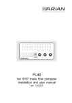
Download Flow Cad software V2.0 Users manual.
Transcript
Flow Cad software V2.0 Users manual. ____________________________________________________________________________ 1 Flow Cad software V2.0 Users manual, rev. c, www.arian.cl 1.0 The FL40 flow computer. 2.0 Arian ISO-5167 Flow Cad software. 3.0 Start up. 3.1 General description 3.2 Setting up flow conditions. 3.3 Setting up flow units. 3.4 Calculation results. 4.0 Fluids 4.1 Steam 4.2 Natural gas 4.3 Defined fluids library 4.3.1 Editing a fluid 4.3.2 Lookup tables 4.3.3 Using Aiche Dippr 801 coefficients 4.3.4 Density for gases 4.3.5 Density for liquids 4.3.6 Viscosity, gases 4.3.7 Viscosity, liquids 4.3.8 Isentropic expansion coefficient 4.4 Nist library 4.4.1 Installing Nist database 4.4.2 Nist fluid types and selection. 4.4.3 Custom mixtures. 4.4.4 Generating tables. 5.0 Primary device 5.1 Iso5167 Primary Device 5.2 Volumetric input mass flow 5.2.1 General volumetric case 5.2.2 Vortex flow meter 5.3 Spyrax sarco Gilflo ILVA primary element 5.4 McCrometer V-Cone or Wafer-Cone 6.0 Instrument parameters. 6.1 Setting instrument parameters. 6.2 Uploading configuration to the FL40 References 4 5 6 6 9 9 10 12 12 13 14 15 15 15 17 18 18 19 19 20 20 20 22 23 25 25 27 27 29 30 31 32 32 33 34 ____________________________________________________________________________ 2 Flow Cad software V2.0 Users manual, rev. c, www.arian.cl ____________________________________________________________________________ 3 Flow Cad software V2.0 Users manual, rev. c, www.arian.cl 1.0 The FL40 flow computer. The FL40 is a powerful multivariable flow computer specifically designed for use on primary devices designed under the ISO5167 standard but can be used also in other devices as will be described in the present manual. Calculates actual mass flow from the 3 following parameters measured continuously dP P1 T1 Differential pressure input (e.g. 4-20ma, 0-10V,..) Up stream fluid pressure input (e.g. 4-20ma, 0-10V,..) Up stream fluid temperature input (Pt100, thermocouples, 4-20ma, 0-10V) The fluid physical properties are stored on the FL40 so it calculates actual mass flow rate or volumetric flow if you prefer. Additionally haves a 6 digit flow totalizer with alarms and communications functionalities that are described in detail in it’s user manual. Here we will concentrate on describing the input configuration for the FL40 witch is done with the help of the Arian Flow Cad software. ____________________________________________________________________________ 4 Flow Cad software V2.0 Users manual, rev. c, www.arian.cl 2.0 Arian ISO-5167 Flow Cad software. The Arian Flow Cad software is used for calculating discharge coefficient and expansion factor as ISO5167 describes. The software generates a configuration file that is downloaded to the FL40 with the RPS PC configuration system. So you don’t need to introduce manually a large set of configuration parameters. Is strongly recommend to have a copy of the ISO 5167 document while you read this manual. To install the software you will need a PC computer with -windows 95 operating system or better. -svga 800x600 color monitor. Uncompress it in any empty folder of your PC. That is all what you need to do, you are ready for start up. Since the program does not make any change on windows registry, you may just delete all the files on the folder to uninstall it. ____________________________________________________________________________ 5 Flow Cad software V2.0 Users manual, rev. c, www.arian.cl 3.0 Start up. ___________________________________________________________________________ 3.1 General description Since flow cad version 2 had become larger and more complete, we will follow several prepared examples to explain how it works. Execute application ArianFlowCad_V2.exe, you will get the main form: The context menus are the following [File / Open] [File / Save] [File / Save as] [File / Report] [File / Exit] Opens a new project file with extension .fld Saves the project file. Saves with different name. Generates a project report files to be printed later. In this example (filename.flw) will generate filename _Report.txt and filename_Report_Data.csv Quits [Fluid] [Device] [Notes] [Instrument] Select and edit fluid properties. Select the primary device type. Add here comments about the project. Configuration files generation for the FL40b On the program go to [ File / Open ] in the upper context menu and open files\examples\example_Air.flw This is an example for air flowing on a orifice plate as you may check going to [ fluid ] and [Device] menus. ____________________________________________________________________________ 6 Flow Cad software V2.0 Users manual, rev. c, www.arian.cl ____________________________________________________________________________ 7 Flow Cad software V2.0 Users manual, rev. c, www.arian.cl Now press the “calculate” command and you must obtain something like this. As you may see this example is for air flowing thru a 100mm bore orifice plate in a 200mm pipe at any flow condition in a range from 1 to 2 Atm fluid upstream pressure, 0C to 30C temperature and 800 to 2400 Pa differential pressure on the orifice plate. Calculation results are given in the lower frame as 8 lines corresponding to the combination of the 2 limits (min. and max. ) given for P, T, dP as specified in the [ Flow Conditions ] frame. You may think as 3 dimensional space composed of 3 axes P, T and dP delimited by minimum and maximum values, this way defining a cube with 6 side planes and 8 corner points. Each line on the list represents a corner point in the cube and any actual flow condition corresponds to a point inside this hypothetical cube. ____________________________________________________________________________ 8 Flow Cad software V2.0 Users manual, rev. c, www.arian.cl ___________________________________________________________________________ 3.2 Setting up flow conditions. P Upstream fluid pressure range must be contained within this limits. If your pressure sensor/transmitter measures absolute pressure (referred to absolute vacuum) then select “Absolute” units. But if the sensor measures relative to atmospheric pressure, then you must set “Gauge” units and specify the actual atmospheric pressure. T Upstream fluid temperature range must be within this range. dP Differential pressure range maximum and minimum you expect to have. The minimum can not be cero, mainly because ISO5167 needs a minimum Reynolds number of about 4000 typically. With cero differential pressure you have cero fluid linear velocity and cero Reynolds. ___________________________________________________________________________ 3.3 Setting up flow units. Qm Set the mass flow units on witch you want the results to be presented. Mass units can be of the volumetric equivalent type e.g. standard cubic feet or standard cubic meter. If you set volumetric equivalent mass flow units for mass flow rate, the you must then specify the standard conditions (pressure and temperature). For example if you are working with air : Qm = Stnd(Cubic Ft) Standard Conditions = 1 Atm , 21 C Then the mass flow rate will be expressed in units of mass equivalent to the mass contained in 1 cubic feet of air at 1Atm and 21C. That is 33.96 grams. Qv Same as previous but for volume flow units. Velocity Same as previous but for linear velocity. ____________________________________________________________________________ 9 Flow Cad software V2.0 Users manual, rev. c, www.arian.cl ___________________________________________________________________________ 3.4 Calculation results. On pressing calculate command you obtain in the lower 8 line lower frame the detailed flow conditions, fluid properties and results for the orifice plate flow as follows. First 3 columns are P, T, and dP in the units specified in the [ flow conditions frame ] The next 3 columns are the following fluid physical calculated properties : Density ( ρ1 ) for the fluid at specified T, P limits in MKS units always. Viscosity ( µ1 ) of the fluid at specified T, P limits in Pascal*Sec units. Remember that 1 Pa*Sec = 1000 (centi Poise) Isentropic exponent ( k ) of the fluid at specified T, P limits (dimensionless). Following columns contain measuring device ( ISO 5167 orifice plate in this case) results and information. Qm Mass flow rate ( QM ) in specified units. Qv Volumetric flow rate ( QV ) in specified units. Velocity Fluid linear velocity (υ1 ) in specified units. Re(D) upstream Reynolds number ( Re D ) C discharge coefficient ( C ) Expansion factor ,upstream ( ε 1 ) P loss The pressure loss is the difference in static pressure between the pressure measured at the wall on the upstream side of the primary device at a section where the influence of the approach impact pressure adjacent to the plate is still negligible (approximately D upstream of the primary device) and that measured on the downstream side of the primary device where the static pressure recovery by expansion of the jet may be considered as just completed (approximately 6D downstream of the primary device). ____________________________________________________________________________ 10 Flow Cad software V2.0 Users manual, rev. c, www.arian.cl This is good approximation (not exact) for the effect of the primary device on flow before it is installed. Must not be confused with dP, the pressure difference on the primary element walls. In general is expected to have dP larger than P loss. Uncertainty % The quadratic sum for the estimated uncertainty of C and estimated uncertainty in ε 1 as predicted by the ISO5167 standard. This is the uncertainty on the flow rate QM , if no additional errors are made on measurements. For details refer to ISO5167-:1991, Section 11.2.2 ISO5167 Condition not satisfied This last column expresses if the ISO5167 standard is satisfied or not. If you read the document you will find that there are several restrictions on the bore and pipe diameter, the Reynolds number, etc. This restriction comes from the fact that the ISO standard was obtained from experimental results that are bounded under certain limits. Is important to take care in being within the ISO5167 limits unless you want the uncertainty on C and ε 1 to be undetermined. The ISO standard warranties that errors uncertainties are predicted. So you must change your flow limits or primary device if you find a message in this column. The message will tell you which is the limit or restriction that is not satisfied. ____________________________________________________________________________ 11 Flow Cad software V2.0 Users manual, rev. c, www.arian.cl 4.0 Fluids The physical fluid properties needed for flow calculations are density, viscosity and isentropic (this last one only for gases). Arian Flow Cad V2, comes with routines and tables for the typical most common fluids such as steam, natural gas , air, nitrogen, oxygen and some others. New fluids can be defined by means of programmed formulas or equations, involving for example expansion factor , Aiche coefficients, values for some operating point. Nist database interfaces directly with this software so it can be used if you have the license. The Nist ddl comes with definitions for pure fluids, mixes and rules for creating custom mixes. ___________________________________________________________________________ 4.1 Steam Steam properties are calculated using the IAPWS Industrial Formulation 1997 for the Thermodynamic Properties of Water and Steam ( www.iapws.org ) The following 3 cases are considered: Super heated steam T, P measured. Steam at a temperature higher than the boiling temperature at the working pressure conditions. Is needed to measure both pressure and temperature. Saturated steam, P only measured. Upstream pressure is the same of the chamber where steam is produced. (water boiled). Pressure is measured and the steam temperature calculated from tables. For example at 1Atm water boils at 100C, at 1.2Atm boils at 105C, etc. Saturated steam, T only measured. This is the similar to the last case but temperature is measured. Pressure is obtained from “vapor pressure” tables from measured temperature. ____________________________________________________________________________ 12 Flow Cad software V2.0 Users manual, rev. c, www.arian.cl ___________________________________________________________________________ 4.2 Natural gas The AGA No.8 DC92 formulas are used as described on ISO12213 document for computing natural properties. Natural gas may have different compositions, so for a particular case molar concentration in % of each component must be specified. Normalize button is used for setting the sum of molar concentrations equal to 100%. This is done multiplying all concentrations by a fixed constant that modifies each individual concentration in order to be the sum 100%. Selected components can be set as fixed so their molar % will not change on normalization. ____________________________________________________________________________ 13 Flow Cad software V2.0 Users manual, rev. c, www.arian.cl ___________________________________________________________________________ 4.3 Defined fluids library Fluids from library are specified by separated for density, viscosity and isentropic coefficient and each of this properties by formulas, Aiche Dippr801 database coefficients or previously generated lookup tables. Specified or defined fluids are stored as files on the /lib folder. You may select the defined fluid with the [ Ok ] command or modify it with the [ Edit ] command. For creating a new fluid, edit a defined one and change fluid name. ____________________________________________________________________________ 14 Flow Cad software V2.0 Users manual, rev. c, www.arian.cl 4.3.1 Editing a fluid The following are edit form parameters and functions. Name file name on /lib folder that will contain the fluid information. Formula optional short formula information. State must be specified for the working fluid Description short optional description of the fluid. Notes optional larger text for fluid description. Test frame allows to check density, viscosity and isentropic coefficient for a specified working point. Density, viscosity and isentropic coefficient are edited in separated forms each containing specific formulas and methods now described. 4.3.2 Lookup tables Lookup tables are text files stored in /lib/tables folder with extensions *.TBD , *.TBV , *.TBK for density , viscosity and isentropic expansion coefficient respectively. Tables are generated with this same program when the /nist/refprop.dll file is available, that is when you have installed the NIST Reference fluid thermodynamic and transport properties database (REFPROP) V9.0 or later www.nist.gov/srd/nist23.cfm. But if you don’t have installed NIST database, still generated tables can be used with the advantage of having more speed since tables are pre-calculated data. 4.3.3 Using Aiche Dippr 801 coefficients Aiche Dipprr801 database coefficients may be used if you have the database. Examples using this coefficients for Acetone, ethane and water are provided. Information for those examples are in web site www.aiche.org/dippr where you may buy the complete database for over 2000 components. Dipprr801 database use formulas and coefficient sets to be used for each compound. Some of the formulas are the following: Formula # 100 Y = A + BT + CT 2 + DT 3 + ET 4 101 B Y = exp A + + C ln(T ) + DT E T 102 Y = AT B C D 1+ + 2 T T ____________________________________________________________________________ 15 Flow Cad software V2.0 Users manual, rev. c, www.arian.cl 103 −C Y = A + B exp D T 104 Y = A+ 105 A Y= X B 106 107 B C D E + 3 + 8 + 9 T T T T Y = A(1 − Tr ) T and Tr = TC T with X = 1 + 1 − C X D with X = B + CTr + DTr + ETr 2 C T Y = A + B sinh C T ( ) 2 E + D T cosh E T 3 2 ( ) For example, water liquid density is obtained by formula 100 with precision < 0.2% in the range 273.16K to 353.15K using the following coefficients: A = -1.3851E+01 B = 6.4038E-01 C = -1.9124E-03 D = 1.8211E-06 E = 0 ____________________________________________________________________________ 16 Flow Cad software V2.0 Users manual, rev. c, www.arian.cl 4.3.4 Density for gases __________________________________________________________ Constant Sets a constant density __________________________________________________________ Look up table __________________________________________________________ Real Gas Equation, Z constant Density is calculated using the real gas equation P ZRT d = Mw Mw Molecular weight gr/mol Z Compressibility factor, Z = 1 for ideal gases R =8.314472E3 Pa M3 / K / mol __________________________________________________________ Real Gas Equation, Z as Redlich-Kwong Same real gas equation but Z is calculated solving Redlich-Kwong formula: Z 3 − Z 2 − ( B 2 + B − A) Z − AB = 0 1 A= 9( 2 B= (2 Tr = T Pr = P 1 3 Pr 2.5 − 1) Tr 1 3 − 1) Pr 3 Tr TC PC with TC = critical temperature. with PC = critical pressure. __________________________________________________________ Aiche Dippr801 second virial SVR Second virial coefficient (b) is obtained from Aiche formula 104. Then molar density is obtained form the equation: − P + ρ + bρ 2 = 0 RT d = ρ * Mw ____________________________________________________________________________ 17 Flow Cad software V2.0 Users manual, rev. c, www.arian.cl 4.3.5 Density for liquids __________________________________________________________ Constant Liquids are incompressible fluids, density changes on temperature and pressure changes are small so a constant could be a good approximation. __________________________________________________________ Look up table __________________________________________________________ Aiche Dippr801 liquid density LDN Usually formulas 105 or 100 are used for liquid density. 4.3.6 Viscosity, gases __________________________________________________________ Constant Sets a constant value for viscosity __________________________________________________________ Look up table __________________________________________________________ Aiche Dippr801 Gas viscosity VVS Commonly Aiche formula 102 is used. Note that setting C=D=0 you obtain the exponential equation AT B approximation AT B C D 1+ + 2 T T Aiche formula 102 µ= Exponential approximation µ = AT B If you have two known viscosities at a nearby operating temperature, e.g. µ 2 at temperature T2 and µ1 at T1 , solve the following formulas for A ,B and use them in Aiche formula 102 with C=D=E=0 ln µ 2 µ1 B= ln T2 T 1 A= µ2 (T2 ) B ____________________________________________________________________________ 18 Flow Cad software V2.0 Users manual, rev. c, www.arian.cl 4.3.7 Viscosity, liquids __________________________________________________________ Constant __________________________________________________________ Look up table __________________________________________________________ Aiche Dippr801 Liquid Viscosity LVS Commonly Aiche formula 101 is used, but note that you may use Andrade formula if you set C=D=0. Aiche formula 101 B µ = exp A + + C ln(T ) + DT E T Andrade’s formula B µ = exp A + T Andrade equation haves only 2 coefficients A and B , then if you have known viscosities µ 2 at temperature T2 and µ1 at T1 , solve the following formulas for A ,B and use them in Aiche formula 101 with C=D=E=0 ln µ 2 µ1 B= 1 − 1 T T1 2 A = ln (µ 2 ) − B T2 4.3.8 Isentropic expansion coefficient __________________________________________________________ Constant In general, isentropic coefficient is a slow varying property, so it may be approximated by a constant value __________________________________________________________ Look up table __________________________________________________________ Ideal Gas Aiche ICP The isentropic coefficient is calculated using : (C P ) i the ideal gas specific heat at constant pressure. C k i = P CV (C P ) i = i (C P ) i − R (C P ) i is obtained from Aiche formula 107 and R =8.314472E3. __________________________________________________________ Real Gas, Aiche ICP, Redlich-Kwong Z Isentropic exponent is calculated for a real gas using (C P ) i (obtained from Aiche formula 107) and the actual compressibility Z obtained by Redlich-Kwong from Tc and Pc critical parameters. For more information refer to Miller pages 2.112-2.113. ____________________________________________________________________________ 19 Flow Cad software V2.0 Users manual, rev. c, www.arian.cl ___________________________________________________________________________ 4.4 Nist library NIST Reference fluid thermodynamic and transport properties database (REFPROP) V9.0 www.nist.gov/srd/nist23.cfm is not a integral part of this program, it must be purchased apart to the NIST. Once installed it will connect directly to FlowCad software as if it was part of it. ___________________________________________________________________________ 4.4.1 Installing Nist database First you must install NIST REFPROP software in the same PC as FlowCad, following provided instructions. Once done, files will be located by default in: C:/Program Files/Refprop In the /Refprop folder is a file called refprop.dll, and 2 sub folders named Fluids and Mixtures. Place a copy of that file and 2 subfolders in the folder ArianFlowCad/nist Now you must have: ArianFlowCad/nist/Fluids ArianFlowCad/nist/Mixtures ArianFlowCad/nist/CustomMix ArianFlowCad/nist/refprop.dll The /CustomMix folder already was in /nist folder and is not part of the database, will contain your custom defined mixtures. The /Fluid and /Mixtures folders contain files corresponding to Nist pure and predefined mixtures provided by Nist. ___________________________________________________________________________ 4.4.2 Nist fluid types and selection. Now can be used the Nist database from Arian Flow Cad selecting the Nist option from the fluid selection frame. There are three types of fluids: pure, mixtures and custom mixtures. Pure fluids and Mixtures are provided by Nist, custom mixtures are user defined using Nist mixture rules for the pure components used in the mixture. Is necessary to specify first the phase state you are expecting to have at operating conditions for your selected fluid. With the [ Ok ] command you select the fluid and with [ Information ] you may obtain information about general properties for the selected fluid and also test it at some T, P point ____________________________________________________________________________ 20 Flow Cad software V2.0 Users manual, rev. c, www.arian.cl If it’s a mixture then information about components is presented. ____________________________________________________________________________ 21 Flow Cad software V2.0 Users manual, rev. c, www.arian.cl ___________________________________________________________________________ 4.4.3 Custom mixtures. Selecting custom mix type and by pressing [Information command ] you will have the following form: If you are creating a new custom mix, modify “New file name” field , before saving Modify the mixture with Add and Remove component commands, specifying the molar fractions for the new component and if it will be fixed or variable. With the normalize command, the variable molar fractions will be adjusted in order to have a total sum of molar fractions equal one. Short name field is an optional text for reference. Is recommended to test the fluid at a typical T, P operating point for your project . ____________________________________________________________________________ 22 Flow Cad software V2.0 Users manual, rev. c, www.arian.cl ___________________________________________________________________________ 4.4.4 Generating tables. Tables containing density, viscosity and isentropic exponent may be generated for any pure, mixture or custom mixture fluid from the Nist fluid selection frame by pressing the [Table generate] command. Generated tables will be stored in the /lib/tables folder for later use in this same PC or in other that doesn’t have the Nist database installed. Table file name Table file name to be stored in /lib/tables. Information notes Optional reference text for the table. Property Select the property for witch the table will be made, file extensions will be .tbd, .tbv, .tk depending on the property selected. In the table range frame you must specify the upper and lower limits of the table for temperature and pressure and also the number of points contained. ____________________________________________________________________________ 23 Flow Cad software V2.0 Users manual, rev. c, www.arian.cl The table may have for example 20 temperature points for range from 300 to 400 Kelvin and 4 pressure points from 100000 to 1E6 Pascal. This way the table will contain 20*4 = 80 points , any intermediate T, P point will be interpolated with the 4 nearest points. Pressing the generate command the table is generated, but not stored. In the precision frame is presented the maximum error expected for the table and the T, P point where was found. In general the more the points in the table, more precision. In the middle frame, four T,P lines are listed with properties and phase state for the lower and upper T and P limits. The software will check that the phase state in those limit points is same you already specified in the previous “Nist fluid selection” form. No phase change is allowed within the table. Finally the lower frame is the table data itself that will be stored in /lib/tables folder when [Save] command pressed. ____________________________________________________________________________ 24 Flow Cad software V2.0 Users manual, rev. c, www.arian.cl 5.0 Primary device Primary device type is selected from the Device menu and may be of the types described as follows. ___________________________________________________________________________ 5.1 Iso5167 Primary Device This option is for primary devices described on ISO5167 document. Iso Type Select the standard under you want to do the calculations. Iso5167-1:1991 Sec.8 Orifice plate Iso5167-1:1991 Sec.9 Nozzle Iso5167-1:1991 Sec.10 Venturi tube Iso5167-1:1991 Sec.10.1 Venturi tube Iso5167-1:1991 Sec.10.2 Venturi nozzle ____________________________________________________________________________ 25 Flow Cad software V2.0 Users manual, rev. c, www.arian.cl Iso5167-1:1991/Amd.1:1998 Orifice plate Iso5167-2:2003 Orifice plate Iso5167-3:2003 Nozzle Iso5167-4:2003 Venturi tube Case Once the standard is defined, there are usually different cases you must specify. For example for a orifice plate, you must specify this design options: Corner Taps D and D/2 Taps Flange Taps For a nozzle, cases are: ISA 1932 Nozzle Long radius Nozzle Bore diameter (d) You must set the bore diameter and the units (e.g. mm, inch,..) Optionally you may introduce the bore material and the temperature at witch you measured that diameter. This information is used for example in a situation where the primary device will operate with a heat gas at 200C. The bore diameter changes by thermal expansion. Used diameter must be the one at that temperature, but is not easy to put a caliper inside a pipe at 200C. So you may measure the diameter with a caliper at environmental temperature (e.g. 25C) and specify the bore material and temperature of your measurement. The software haves thermal expansion coefficients tables for typical bore and Pipe material and will correct continuously for the diameter at operating temperature. Upstream Pipe diameter (D) Here accounts same considerations as for bore diameter. ____________________________________________________________________________ 26 Flow Cad software V2.0 Users manual, rev. c, www.arian.cl ___________________________________________________________________________ 5.2 Volumetric input flow rate correction Flow cad may be used with volumetric flow meters and compensate with current density to obtain mass flow. Some of them may already have a linear output but others not. In such case you may use a several points table. Applications for the table can be also for open channel flow measurement where you may describe the flow level relation in the table. The mass input table option is when you already have a mass flow rate ( eg. from a coreolis) and you need to have the volumetric flow rate for verification porpuses. 5.2.1 General volumetric case Typical applications are positive displacement devices that have a pulse output proportional to the flow. At lower end viscosity effects makes pulse frequency slower inducing a non-linear but repeatable behavior. For example, the manufacturer provides the following table with 4 points: Frequency Flow (cubic meter/hour) 0Hz 0 500Hz 1384 1000Hz 2281 1500Hz 3034 This example is files\examples\turbine1.flw file. The maximum specified pulse output for the device is 2000Hz and is connected to a 420mA transmitter scaled as 0-2000Hz . The 4-20mA will be the Fl40 main input. In this case our “User Units” are the frequency 0-2000Hz. Table will be introduced specifying the number of points, units and upper end as follows: ____________________________________________________________________________ 27 Flow Cad software V2.0 Users manual, rev. c, www.arian.cl Graphic is intended for verification purposes, e.g. verifying you have correctly introduced table data expecting to have a regular curve. Table points are represented in the graphic as green circles. rd Data is interpolated between table points using 3 order polynomials segments for having a smooth curve instead of a set of straight segments. Refresh command draws or refreshes the graphic with new table data. The “test point” frame evaluates the curve at any point, for example with 180Hz , flow is 554.34 M3/Hour. Later when configuring the Fl40 flow computer in the [Instrument] tab , you will have to use this same user units in the input setup. ____________________________________________________________________________ 28 Flow Cad software V2.0 Users manual, rev. c, www.arian.cl 5.2.2 Vortex flow meter Vortex flow meters give a linear volumetric flow output, there is no need to specify more than 2 points for the table. For example a vortex flow meter that measures steam haves a 4-20ma output corresponding to 0 - 4500 cubic meter/hour. (open file files\examples\vortex.flw) In this case we will set an auxiliary scale 0 – 100% and refer to it as our user units. Same as previous example, later when configuring the flow computer in the [Instrument] tab , you will have to use this 0 –100 user units in the input setup. ____________________________________________________________________________ 29 Flow Cad software V2.0 Users manual, rev. c, www.arian.cl ___________________________________________________________________________ 5.3 Spyrax sarco Gilflo ILVA primary element Arian flow cad can be used with Spyrax Sarco ILVA devices. For example load the file located in /files/examples/ Spyrax_sarco_ILVA.flw , and go to Device menu, there you will find the following DN150 ILVA device example. Data is provided by the manufacturer on your device calibration document . ____________________________________________________________________________ 30 Flow Cad software V2.0 Users manual, rev. c, www.arian.cl ___________________________________________________________________________ 5.4 McCrometer V-Cone or Wafer-Cone Load the example file located in /files/examples/ McCrometer_Vcone.flw , and go to Device menu, you will find the following V-cone example. You must fill the Cd (discharge coefficient) vs Reynolds number table provided by the manufacturer as well as the v-cone size. With the “Calibration verification test point” frame you may test the device for a specified fluid (density, viscosity, isentropic coefficient provided) at a T,P operating point when a differential pressure dP is present on the element. Results will be the estimated mass flow on the device. ____________________________________________________________________________ 31 Flow Cad software V2.0 Users manual, rev. c, www.arian.cl 6.0 Instrument parameters. Once made the calculations and no restrictions reported you may prepare FL40 flow computer configuration. 6.1 Setting instrument parameters. Open the example file on \files\examples\Air.flw. On the main menu first press the [Calculate] command to verify there is no comments or problems, then go to [Instrument] menu where you will have the following form: Specify up-stream pressure sensor calibrated limits on the [Pressure sensor] frame. Low and high are the pressure values at low and high scale of the sensor (e.g. 4ma-20ma or 0v-10v). Later on the instrument you will set the input type, but now you must specify limits only. Set also the units type depending on transmitter type (absolute or gauge units). The same must be done for differential pressure transmitter scale on the [Differential pressure sensor] frame. ____________________________________________________________________________ 32 Flow Cad software V2.0 Users manual, rev. c, www.arian.cl On the [Flow rate display] frame you set the flow rate type, units and scale for the mass a volumetric rates that the FL40 will display. If you need to have some custom flow rate units set the constant [k mult] to be multiplied to the flow rates, other way this constant must be 1. Flow rates will be calculated internally in floating point format so you may set the decimal places you need in the configuration menu of the FL40. Only take care that if you will use the lower 4 digit display for a flow rate, then the maximum display would be 9999. Check that on operating conditions this number never be exceeded. If necessary then use [k mult] =0.001 for example. When you press [Calculate], the contents of the bottom list will be calculated, they are listed for the 8 limit conditions. Display column shows exactly what will be the 4 digit rate reading on the FL40. Test different values for K by pressing [Calculate] command in order to have different display readings and select the better option. Arian flow cad is intended to configure and set up the flow measurement on the Fl40 mass flow meter, its output will be a configuration file. Pressing the [Config File] button will generate that configuration file *.sfg ( e.g. “Air.sfg” in this case) containing binary data to be downloaded to the FL40 using the RPS software. It will be placed in the same folder of the project file (e.g. files\examples\) Also is generated file Air.csv ( coma separated variables format) containing a list of calculated flow rates for different conditions, it can be opened as a spread sheet. 6.2 Uploading configuration to the FL40 By other side the RPS (remote programming software) application will upload the *.sfg file and also help you setting other FL40 parameters such as alarms, pressure inputs type, temperature input type, 4-20ma outputs and communications. Place a copy of the Air.sfg configuration file in the "\rps\files" subdirectory of the RPS software. Then run RPS software with the FL40 connected to the PC and go to menu [Device] > [File write] and select the Air.sfg when requested. Refer to the FL40 users manual and the RPS software manual for more information. ____________________________________________________________________________ 33 Flow Cad software V2.0 Users manual, rev. c, www.arian.cl References ISO-5167: ISO-5167-1:1991(E) Measurement of fluid flow by means of pressure differential devices. Part1: Orifice plates, Nozzles and Venturi tubes inserted in circular cross-section conduits running full. Ref. No.: ISO5167-1:1991(E) ISO-5167-1:1991/Amd.1:1998(E) Amendment ISO-5167: Measurement of fluid flow by means of pressure differential devices inserted in circular cross-section conduits running fullPart1: General principles and requirements, Second edition, 2003-03-01, Ref. No.: ISO 5167-1:2003(E). Part2: Orifice plates, Second edition, 2003-03-01, Ref. No.: ISO 5167-2:2003(E). Part3: Nozzles and Venturi Nozzles, Second edition, 2003-03-01, Ref. No.: ISO 51673:2003(E). Part4:Venturi tubes, Second edition, 2003-03-01, Ref. No.: ISO 5167-4:2003(E). AGA No.8 DC92: Starling, K.E., Savidge, J.L.: Compressibility Factors for Natural Gas and Other Hydrocarbon Gases", American Gas Association (AGA) Transmission Measurement Committee Report No. 8, American Petroleum Institute (API) MpMS, chapter 14.2, second edition, November 1992. ISO 12213: Natural gas - Calculation of Compression factor Part1: Introduction and guidelines Part2: Calculation using molar-composition analysis IAPWS-IF97: Release on the IAPWS Industrial Formulation 1997 for the Thermodynamic Properties of Water and Steam The International Association for the Properties of Water and Steam, Erlangen, Germany, September 1997, www.iapws.org NIST: Reference fluid thermodynamic and transport properties database (REFPROP) V9.0 www.nist.gov/srd/nist23.cfm. General: Richard W. Miller, Flow Measurement Engineering Handbook. Third edition McGraw-Hill. ISBN0-07-042366-0 ____________________________________________________________________________ 34 Flow Cad software V2.0 Users manual, rev. c, www.arian.cl


