1
CONTENTS
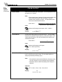
SAFETY INSTRUCTIONS .............................................................................................................. 1
1. INTRODUCTION
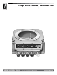
1.1 Unit Description ............................................................................................................ 2
1.2 Specifications ............................................................................................................... 3
2. INSTALLATION
2.1 General Mounting Hints ............................................................................................. 10
2.2 Mounting Diagrams .................................................................................................... 10
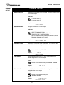
3. APPLICATIONS
3.1 Steam Mass ............................................................................................................... 13
3.2 Steam Heat ................................................................................................................ 14
3.3 Steam Net Heat .......................................................................................................... 15
3.4 Steam Delta Heat ....................................................................................................... 16
3.5 Corrected Gas Volume ............................................................................................... 17
3.6 Gas Mass ................................................................................................................... 18
3.7 Gas Combustion Heat ................................................................................................ 19
3.8 Corrected Liquid Volume ............................................................................................ 20
3.9 Liquid Mass ................................................................................................................ 21
3.10 Liquid Combustion Heat ........................................................................................... 22
3.11 Liquid Sensible Heat ................................................................................................ 23
3.12 Liquid Delta Heat ...................................................................................................... 24
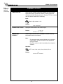
4. WIRING
4.1 Terminal Designations ................................................................................................ 25
4.2 Typical Wiring Connections ........................................................................................ 26
4.2.1 Flow Input ................................................................................................... 26
4.2.2 Stacked DP Input ....................................................................................... 26
4.2.3 Pressure Input ............................................................................................ 26
4.2.4 Temperature Input ...................................................................................... 27
4.2.5 Temperature 2 Input ................................................................................... 27
4.3 Wiring In Hazardous Areas ........................................................................................ 28
4.3.1 Flow Input ................................................................................................... 28
4.3.2 Pressure Input ............................................................................................ 28
4.3.3 Temperature Input ...................................................................................... 28
5. UNIT OPERATION
5.1 Front Panel Operation Concept for Operate Mode .................................................... 29
5.2 General Operation ...................................................................................................... 30
5.3 Password Protection .................................................................................................. 30
5.4 Relay Operation ......................................................................................................... 30
5.5 Pulse Output ............................................................................................................. 30
5.6 Analog Outputs ........................................................................................................... 30
5.7 Function Keys; Display Grouping .......................................................................... 30
5.8 RS-232 Serial Port Operation .................................................................................... 31
5.8.1 PC Communications .................................................................................. 31
5.8.2 Operation of RS-232 Serial Port with Printers ............................................ 31
5.9 RS-485 Serial Port Operation .................................................................................... 31
5.10 Pause Computations Prompt ................................................................................... 31
6. PROGRAMMING
6.1 Front Panel Operation Concept for Program Mode ................................................... 32
6.2 EZ Setup .................................................................................................................... 33
6.3 Detailed Menu Descriptions ....................................................................................... 34
6.4 System Parameters .................................................................................................... 36
6.5 Display ....................................................................................................................... 41
6.6 System Units .............................................................................................................. 43
6.7 Fluid Data ................................................................................................................... 50
6.8 Flow Input ................................................................................................................... 55
6.9 Other Input ................................................................................................................. 67
6.10 Pulse Output ............................................................................................................ 70
6.11 Current Output .......................................................................................................... 73
6.12 Relays ...................................................................................................................... 75
6.13 Communication ........................................................................................................ 79
6.14 Network Card ........................................................................................................... 88
6.15 Service & Analysis .................................................................................................... 89
CONTENTS
7. PRINCIPLE OF OPERATION
7.1 General ...................................................................................................................... 97
7.2 Square Law Flowmeter Considerations ..................................................................... 97
7.3 Flow Equations ........................................................................................................... 97
7.3.1 Flow Input Computation ............................................................................. 97
7.3.2 Pressure Computation ............................................................................... 98
7.3.3 Temperature Computation .......................................................................... 98
7.3.4 Density/Viscosity Computation ................................................................... 98
7.3.5 Corrected Volume Flow Computation ........................................................ 99
7.3.6 Mass Flow Computation ........................................................................... 100
7.3.7 Combustion Heat Flow Computation ....................................................... 100
7.3.8 Heat Flow Computation ............................................................................ 101
7.3.9 Sensible Heat Flow Computation ............................................................. 101
7.3.10 Liquid Delta Heat Computation .............................................................. 101
7.3.11 Expansion Factor Computation for Square Law Flowmeters ................. 101
7.3.12 Uncompensated Flow Computation ....................................................... 102
7.4 Computation of the D.P. Factor ................................................................................ 103
8. RS-232 SERIAL PORT
8.1 RS-232 Serial Port Description ................................................................................ 104
8.2 Instrument Setup by PC Over Serial Port ................................................................ 104
8.3 Operation of Serial Communication Port with Printers ............................................. 104
8.4 SP4000 RS-232 Port Pinout .................................................................................... 104
9. RS-485 SERIAL PORT
9.1 RS-485 Serial Port Description ................................................................................ 105
9.2 General .................................................................................................................... 105
9.3 Operation of Serial Communication Port with PC .................................................... 105
9.4 SP4000 RS-485 Port Pinout .................................................................................... 105
10. FLOW COMPUTER SETUP SOFTWARE
10.1 System Requirements ............................................................................................ 106
10.2 Cable and Wiring Requirements ............................................................................ 106
10.3 Installation for Windows™3.1 or 3.11 ..................................................................... 106
10.4 Using the Flow Computer Setup Software ............................................................. 106
10.5 File Tab ................................................................................................................... 107
10.6 Setup Tab ............................................................................................................... 107
10.7 View Tab ................................................................................................................. 108
10.8 Misc. Tab ................................................................................................................ 108
11. GLOSSARY OF TERMS
10 Glossary Of Terms .................................................................................................... 109
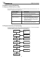
12. Diagnosis and Troubleshooting
12.1 Response of SP4000 on Error or Alarm ................................................................. 112
12.2 Diagnosis Flowchart and Troubleshooting ............................................................. 112
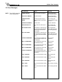
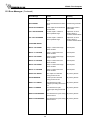
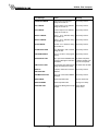
12.3 Error Messages ...................................................................................................... 113
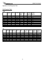
Appendix A
Fluid Properties Table .................................................................................................... 116
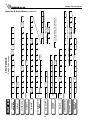
Appendix B - Setup Menus
Setup Menus with Operator Code Access ..................................................................... 117
Setup Menus with Supervisor Code Access .................................................................. 118
Warranty ...................................................................................................................................... 119
Decoding Part Number ................................................................................................................ 119
SP4000 Flow Computer
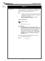
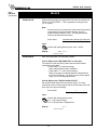
SAFETY INSTRUCTIONS
!
The following instructions must be observed.
•
This instrument was designed and is checked in accordance with
regulations in force EN 60950 (“Safety of information technology
equipment, including electrical business equipment”).
A hazardous situation may occur if this instrument is not used for its
intended purpose or is used incorrectly. Please note operating
instructions provided in this manual.
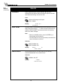
•
The instrument must be installed, operated and maintained by
personnel who have been properly trained. Personnel must read and
understand this manual prior to installation and operation of the
instrument.
•
The manufacturer assumes no liability for damage caused by incorrect
use of the instrument or for modifications or changes made to the
instrument.
Technical Improvements
•
The manufacturer reserves the right to modify technical data without
prior notice.
1
SP4000 Flow Computer
1. Introduction
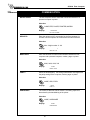
1.1 Unit Description:
The SP4000 Flow Computer satisfies the instrument requirements
for a variety of flowmeter types in liquid, gas, steam and heat
applications. Multiple flow equations are available in a single
instrument with many advanced features.
The alphanumeric display offers measured parameters in easy
to understand format. Manual access to measurements and
display scrolling is supported.
The versatility of the Flow Computer permits a wide measure of
applications within the instrument package. The various hardware
inputs and outputs can be “soft” assigned to meet a variety of
common application needs. The user “soft selects” the usage of
each input/output while configuring the instrument.
The isolated analog output can be chosen to follow the volume
flow, corrected volume flow, mass flow, heat flow, temperature,
pressure, or density by means of a menu selection. Most
hardware features are assignable by this method.
The user can assign the standard RS-232 Serial Port for data
logging, or transaction printing, or for connection to a modem or
two way pager for remote meter reading.
A PC Compatible software program is available which permits
the user to rapidly redefine the instrument configuration.
Language translation option features also permit the user to
define his own messages, labels, and operator prompts. These
features may be utilized at the OEM level to creatively customize
the unit for an application or alternately to provide for foreign
language translations. Both English and a second language
reside within the unit.
NX-19
The NX19 feature is available for Natural Gas calculations where
the user requires compensation for compressibility effects.
Compensation for these compressibility effects are required at
medium to high pressure and are a function of the gas specific
gravity, % CO2, % Nitrogen, as well as temperature and pressure.
The compressibility algorithm used is that for NX-19.
Stacked differential pressure transmitter option
This option permits the use of a low range and high range DP
transmitter on a single primary element to improve flow transducer
and measurement accuracy.
Peak demand option
This option permits the determination of an hourly averaged flow
rate. Demand last hour, peak demand and time/date stamping for
applications involving premium billing.
Data logging option
This option provides data storage information in 64k of battery
backed RAM. Items to be logged, conditions to initiate the log and
a variety of utilities to clear and access the data via the RS-232
port are provided.
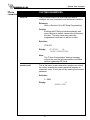
Peak Demand Option
There are applications where customer charges are determined
in part by the highest hourly averaged flowrate observed during
a billing period.
The peak demand option for the SP4000 is intended for
applications where it is important to compute such an hourly
average flowrate, to note the value of the peak occurrence and
the corresponding time and date of that event.
The demand last hour rate is computed based on the current
total and the total 60 minutes prior. This value is recomputed
every 5 minutes.
The peak demand is the highest value observed in the demand
last hour.
The time and date stamp is the time and date at which the
highest peak demand occurred.
The Demand Last Hour and/or Peak Demand can be directly
viewed on the display by pressing the RATE key and then
scrolling through the rates with the ^/v arrow key until the
desired item is viewed.
The Peak Time and Date stamp can be viewed on the display
by pressing the TIME and then scrolling through the time
related parameters using the ^/v arrow keys until the desired
item is viewed.
All of these items can be included into the scrolling display list
along with the other process values and totalizers in a user
selectable list.
The peak demand may be cleared by pressing the CLEAR key
while viewing the PEAK DEMAND or by means of a command
on the serial port.
The Peak Time and Date stamp can be viewed on the display
by pressing the TIME and then scrolling through the time
related parameters using the ^/v arrow keys until the desired
item is viewed.
The Demand Last Hour and Peak Demand can be assigned to
one of the analog outputs. The demand last hour or peak
demand could thusly be output on a recording device such as a
strip chart recorder or fed into a building energy automation
system.
The Demand Last Hour and Peak Demand can be assigned to
one of the relays. The customer can be notified that he is
approaching or exceeding a contract high limit by assigning the
demand last hour to one of the relays and setting the warning
point into the set point. A warning message would also be
displayed.
The peak demand may be used in conjunction with the print list
and data logger to keep track of hourly customer usage
profiles.
The Demand Last Hour, Peak Demand, and Time and Date
Stamp information can be accessed over the serial ports. The
Peak Demand may also be reset over the serial ports.
The peak demand option may also be used as a condition to
call out in remote metering by modem or two way pager.
EZ Setup
The unit has a special EZ setup feature where the user is guided
through a minimum number of steps to rapidly configure the
instrument for the intended use. The EZ setup prepares a series
of questions based on flow equation, fluid, and flowmeter type
desired in the application.
2
SP4000 Flow Computer
Analog Input:
Ranges
Voltage: 0-10 VDC, 0-5 VDC, 1-5 VDC
Current: 4-20 mA, 0-20 mA
Basic Measurement Resolution: 16 bit
Update Rate: 2 updates/sec minimum
Automatic Fault detection: Signal over/under-range,
Current Loop Broken
Calibration: Operator assisted learn mode. Learns Zero
and Full Scale of each range
Fault Protection:
Fast Transient: 1000 V Protection (capacitive clamp)
Reverse Polarity: No ill effects
Over-Voltage Limit:
50 VDC Over voltage protection
Over-Current Protection: Internally current limited
protected to 24 VDC
Optional: Stacked DP transmitter 0-20 mA or 4-20 mA
Pulse Inputs:
Number of Flow Inputs: one
Input Impedance: 10 k Ω nominal
Trigger Level: (menu selectable)
High Level Input
Logic On: 2 to 30 VDC
Logic Off: 0 to .9 VDC
Low Level Input (mag pickup)
Selectable sensitivity: 10 mV and 100 mV
Minimum Count Speed: 0.25 Hz
Maximum Count Speed: Selectable: 0 to 40 kHz
Overvoltage Protection: 50 VDC
Fast Transient: Protected to 1000 VDC (capacitive clamp)
1.2 Specifications:
Environmental
Operating Temperature: 0 to +50 C
Storage Temperature: -40 to +85 C
Humidity : 0-95% Non-condensing
Materials: UL, CSA, VDE approved
Approvals: CE Approved Light Industrial, UL/CSA Pending
Display
Type: 2 lines of 20 characters, VFD
Character Size: 0.3" nominal
User selectable label descriptors and units of measure
Keypad
Keypad Type: Membrane Keypad
Keypad Rating: Sealed to Nema 4
Number of keys: 16
Raised Key Embossing
Enclosure
Enclosure Options: Panel, Wall, Explosion Proof
Size: See Chapter 2; Installation
Depth behind panel: 6.5" including mating connector
Type: DIN
Materials: Plastic, UL94V-0, Flame retardant
Bezel: Textured per matt finish
Equipment Labels: Model, safety, and user wiring
NX-19 Compressibility Calculations
Temperature
-40 to 240 F
Pressure
0 to 5000 psi
Specific Gravity
0.554 to 1.0
Mole % CO2
0 to 15%
Mole % Nitrogen
0 to 15%
Temperature, Pressure, Density Inputs
The compensation inputs usage are menu selectable for
temperature, temperature 2, pressure, density, steam trap
monitor or not used.
Power Input
The factory equipped power options are internally fused. An
internal line to line filter capacitor is provided for added transient
suppression. MOV protection for surge transient is also
supported
Universal AC Power Option:
85 to 276 Vrms, 50/60 Hz
Fuse: Time Delay Fuse, 250V, 500mA
DC Power Option:
24 VDC (16 to 48 VDC)
Fuse: Time Delay Fuse, 250V, 1.5A
Transient Suppression: 1000 V
Calibration: Operator assisted learn mode
Operation: Ratiometric
Accuracy: 0.01% FS
Thermal Drift: Less than 100 ppm/C
Basic Measurement Resolution: 16 bit
Update Rate: 2 updates/sec minimum
Automatic Fault detection:
Signal Over-range/under-range
Current Loop Broken
RTD short
RTD open
Transient Protection: 1000 V (capacitive clamp)
Reverse Polarity: No ill effects
Over-Voltage Limit (Voltage Input): 50 VDC
Over-Current Limit (Internally limited to protect input to
24 VDC)
Flow Inputs:
Flowmeter Types Supported:
Linear FlowmetersTurbine
Square Law Flowmeters- Optional
Other FlowmetersOptional
Available Input Ranges
(Temperature / Pressure / Density / Trap Monitor)
Current: 4-20 mA, 0-20 mA
Resistance: 100 Ohms DIN RTD
100 Ohm DIN RTD (DIN 43-760, BS 1904):
Three Wire Lead Compensation
Internal RTD linearization learns ice point resistance
1 mA Excitation current with reverse polarity protection
Temperature Resolution: 0.1°C
3
SP4000 Flow Computer
Datalogger (optional)
Type: Battery Backed RAM
Size: 64k
Initiate: Key, Interval or Time of Day
Items Included: Selectable List
Data Format: Printer or CSV Access via RS-232 command
Analog Outputs
The analog output usage is menu assignable to correspond
to the Heat Rate, Uncompensated Volume Rate, Corrected
Volume Rate, Mass Rate, Temperature, Density, or Pressure.
(Peak demand and demand last hour optional)
Number of Outputs: 2
Type: Isolated Current Sourcing (shared common)
Isolated I/P/C: 500 V
Available Ranges: 0-20 mA, 4-20 mA (menu selectable)
Resolution: 16 bit
Accuracy: 0.05% FS at 20 Degrees C
Update Rate: 5 updates/sec
Temperature Drift: Less than 200 ppm/C
Maximum Load: 1000 ohms
Compliance Effect: Less than .05% Span
60 Hz rejection: 40 dB minimum
EMI: No effect at 10 V/M
Calibration: Operator assisted Learn Mode
Averaging: User entry of DSP Averaging constant to
cause an smooth control action
Stored Information (ROM)
Steam Tables (saturated & superheated), General Fluid
Properties, Properties of Water, Properties of Air, Natural
Gas
User Entered Stored Information (EEPROM / Nonvolatile
RAM)
Transmitter Ranges, Signal Types
Fluid Properties
(specific gravity, expansion factor, specific heat, viscosity,
isentropic exponent, combustion heating value, Z factor,
Relative Humidity)
Units Selections (English/Metric)
RS-232 Communication
Uses: Printing, Setup, Modem, Two Way Pager, Datalogging
Baud Rates: 300, 600, 1200, 2400, 4800, 9600, 19200
Parity: None, Odd, Even
Device ID: 0 to 99
Protocol: Proprietary, Contact factory for more information
Chassis Connector Style: DB 9 Female connector
Power Output: 8V (150 mA max.) provided to Modem or
Two Way Pager
RS-485 Communication (optional)
Uses: Network Communications
Baud Rates: 300, 600, 1200, 2400, 4800, 9600, 19200
Parity: None, Odd, Even
Device ID: 1 to 247
Protocol: ModBus RTU
Chassis Connector Style: DB 9 Female connector
Excitation Voltage
24 VDC @ 100 mA overcurrent protected
Relay Outputs
The relay outputs usage is menu assignable to (Individually
for each relay) Hi/Lo Flow Rate Alarm, Hi/Lo Temperature
Alarm, Hi/Lo Pressure Alarm, Pulse Output (pulse options),
Wet Steam or General purpose warning (security).
(Peak demand and demand last hour optional)
Number of relays: 2 (3 optional)
Contact Style: Form C contacts (Form A with 3 relay option)
Contact Ratings: 240 V, 1 amp
Fast Transient Threshold: 2000 V
Isolated Pulse output
The isolated pulse output is menu assignable to
Uncompensated Volume Total, Compensated Volume Total,
Heat Total or Mass Total.
Isolation I/O/P: 500 V
Pulse Output Form (menu selectable): Open Collector NPN
or 24 VDC voltage pulse
Nominal On Voltage: 24 VDC
Maximum Sink Current: 25 mA
Maximum Source Current: 25 mA
Maximum Off Voltage: 30 VDC
Saturation Voltage: 0.4 VDC
Pulse Duration: User selectable
Pulse output buffer: 8 bit
Real Time Clock
The Flow Computer is equipped with either a super cap or a
battery backed real time clock with display of time and date.
Format:
24 hour format for time
Day, Month, Year format for date
Daylight Savings Time (optional)
Measurement
The Flow Computer can be thought of as making a series of
measurements of flow, temperature/density and pressure
sensors and then performing calculations to arrive at a result(s)
which is then updated periodically on the display. The analog
outputs, the pulse output, and the alarm relays are also
updated. The cycle then repeats itself.
Step 1: Update the measurements of input signalsRaw Input Measurements are made at each input using
equations based on input signal type selected. The system
notes the “out of range” input signal as an alarm condition.
Step 2: Compute the Flowing Fluid ParametersThe temperature, pressure, viscosity and density equations
are computed as needed based on the flow equation and
input usage selected by the user.
4
SP4000 Flow Computer
Step 3 : Compute the Volumetric FlowVolumetric flow is the term given to the flow in volume units.
The value is computed based on the flowmeter input type
selected and augmented by any performance enhancing
linearization that has been specified by the user.
Step 4: Compute the Corrected Volume Flow at Reference
ConditionsIn the case of a corrected liquid or gas volume flow calculation,
the corrected volume flow is computed as required by the
selected compensation equation.
In the setup menu, the flow computer activates the correct
setup variables based on the instrument configuration, the
flow equation, and the hardware selections made for the
compensation transmitter type, the flow transmitter type, and
meter enhancements (linearization) options selected. All
required setup parameters are enabled. All setup parameters
not required are suppressed.
Also note that in the menu are parameter selections which
have preassigned industry standard values. The unit will
assume these values unless they are modified by the user.
Step 5 : Compute the Mass FlowAll required information is now available to compute the mass
flow rate as volume flow times density. A heat flow computation
is also made if required.
Most of the process input variables have available a “default”
or emergency value which must be entered. These are the
values that the unit assumes when a malfunction is determined
to have occurred on the corresponding input.
Step 6: Check Flow AlarmsThe flow alarm functions have been assigned to one of the
above flow rates during the setup of the instrument. A
comparison is now made by comparing the current flow rates
against the specified hi and low limits.
It is possible to enter in a nominal constant value for
temperature or density, or pressure inputs by placing the
desired nominal value into the default values and selecting
"manual". This is also a convenience when performing bench
top tests without simulators.
Step 7: Compute the Analog OutputThis designated flow rate value is now used to compute the
analog output.
The system also provides a minimum implementation of an
“audit trail” which tracks significant setup changes to the unit.
This feature is increasingly being found of benefit to users or
simply required by Weights and Measurement Officials in
systems used in commerce, trade, or “custody transfer”
applications.
Step 8: Compute the Flow Totals by SummationA flow total increment is computed for each flow rate. This
increment is computed by multiplying the respective flow rate
by a time base scaler and then summing. The totalizer format
also includes provisions for total rollover.
Step 9: Pulse Output ServiceThe pulse output is next updated by scaling the total increment
which has just been determined by the pulse output scaler
and summing it to any residual pulse output amount.
Step 10: Update Display and Printer OutputThe instrument finally runs a task to update the various table
entries associated with the front panel display and serial
outputs.
Instrument Setup
The setup is password protected by means of a numeric lock
out code established by the user. The help line and units of
measure prompts assure easy entry of parameters.
An EZ Setup function is supported to rapidly configure the
instrument for first time use. A software program is also
available which runs on a PC using a RS-232 Serial for
connection to the Flow Computer. Illustrative examples may
be down loaded in this manner.
The standard setup menu has numerous subgrouping of
parameters needed for flow calculations. There is a well
conceived hierarchy to the setup parameter list. Selections
made at the beginning of the setup automatically affect
offerings further down in the lists, minimizing the number of
questions asked of the user.
Simulation and Self Checking:
This mode provides a number of specialized utilities required
for factory calibration, instrument checkout on start-up, and
periodic calibration documentation.
A service password is required to gain access to this
specialized mode of operation. Normally quality, calibration,
and maintenance personnel will find this mode of operation
very useful.
Many of these tests may be used during start-up of a new
system. Output signals may be exercised to verify the electrical
interconnects before the entire system is put on line.
The following action items may be performed in the Diagnostic
Mode:
Print Calibration/Maintenance Report
View Signal Input (Voltage, Current, Resistance, Frequency)
Examine Audit Trail
Perform a Self Test
Perform a Service Test
View Error History
Perform Pulse Output Checkout / Simulation
Perform Relay Output Checkout / Simulation
Perform Analog Output Checkout / Simulation
Calibrate Analog Inputs using the Learn Feature
Calibrate Analog Output using the Learn Feature
Schedule Next Maintenance Date
Note that a calibration of the analog input/output will advance
the audit trail counters since it effects the accuracy of the
system.
5
SP4000 Flow Computer
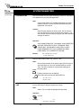
Operation of Steam Trap Monitor
In applications on Saturated Steam, the otherwise unused
Compensation Input may be connected to a steam trap
monitor that offers the following compatible output signal levels:
4mA = trap cold
12 mA = trap warm and open (blowing)
20 mA = trap warm and closed
The user can also define whether he just wants the data
stored into the datalogger, or if he wants the data both stored
in the datalogger and sent out over the RS232 port in the
DATALOG ONLY menu.
The user can define the format he wishes the data to be
output in using the DATALOG FORMAT menu. Choices are
PRINTER and DATABASE. PRINTER format will output the
data records in a form suitable to dump to a printer. DATABASE
format will output the values in a CSV, or Comma Separated
Variable with Carriage return delimiting of each record.
In normal operation a steam trap is warm and periodically
opens and closes in response to the accumulation of
condensate. A cold trap is indication that it is not purging the
condensate, a trap that is constantly blowing is an indication
that it is stuck open. To avoid a false alarm, the SP4000
permits the user to program a delay, or time period, which
should be considered normal for the trap to be either cold, or
open. An alarm will only be activated if the trap is detected as
continuously being in the abnormal states for a time period
greater than this TRAP ERROR DELAY time.
A number of serial commands are also included to access
and manipulate information stored with in the datalogger.
Among these RS232 command capabilities are the following
actions:
Clear Data Logger
Send all Data in Datalogger
Send Only New Data since Datalogger was last Read
Send Data for the date included in the request
Send the column heading text for the CSV data fields
Send the column units of measure text for the CSV data
fields
Store one new record into datalogger now
Read Number of New Records in the datalogger
Read number of records currently in the datalogger
Read the maximum number of records capacity of the
datalogger
Move Pointer Back N records
Dump Record at Pointer
Dump records newer than pointer
Dump data from N records back
The user selects to use the Compensation Input for Trap
Monitoring by selecting “4-20mA TRAP STATUS as the INPUT
SIGNAL for OTHER INPUT1.
The user can program the ERROR DELAY time in HH:MM
format into both the TRAP ERROR DELAY (cold trap error)
menu and the TRAP BLOWING DELAY (trap stuck open)
menu.
The SP4000 will warn the operator of a TRAP ERROR when
an abnormal condition is detected. The error can be
acknowledged by pressing the ENTER key. However, the
problem may reassert itself if there is a continued problem
with the steam trap.
The datalogger option is used in conjunction with the RS-232
port in remote metering applications.
In addition, the event is noted in the ERROR LOG.
It is also possible for the user to program a trap malfunction
as one of the conditions worthy of a CALL OUT of a problem
by selecting this error in the ERROR MASK.
The technical details associated with the serial commands
are listed in Universal Serial Protocol Manual available upon
request.
RS-232 Serial Port
The Flow Computer has a general purpose RS-232 Port
which may be used for any one of the following purposes:
The Data-Logging option of the SP4000 can also be used to
log the performance of the trap by storing the % of time the
trap has been cold, and/or blowing open during the datalog
interval.
Transaction Printing
Data Logging
Remote Metering by Modem
Remote Metering by Two Way Pager
Computer Communication Link
Configuration by Computer
Print System Setup
Print Calibration/Malfunction History
Datalogging Option
The Datalogging Option for the SP4000 permits the user to
automatically store sets of data items as a record on a periodic
basis. A datalog record may be stored as the result of either a
PRINT key depression, or an INTERVAL, or a TIME OF DAY
request for a datalog.
The user defines the list of items to be included in each
datalog by selecting these in the PRINT LIST menu located
within the COMMUNICATIONS SUBMENU.
Instrument Setup by PC’s over Serial Port
A Diskette program is provided with the Flow Computer
that enables the user to rapidly configure the Flow Computer
using an Personnel Computer. Included on the diskette are
common instrument applications which may be used as a
starting point for your application. This permits the user to
have an excellent starting point and helps speed the user
through the instrument setup.
The user selects what will trigger a datalog record being
stored in the PRINT INITIATE menu. The choices are PRINT
KEY, INTERVAL, and TIME OF DAY.
The user can select the datalog store interval in a HH:MM
format in the PRINT INTERVAL menu.
The user can also select the store time of day in a 24 hr
HH:MM format in the PRINT TIME menu.
6
SP4000 Flow Computer
In most applications using modem communications, the
SP4000’s RS232 USAGE is first set equal to MODEM.
Each SP4000 on a shared modem cable is given a unique
serial device address or DEVICE ID. The BAUD RATE is
commonly set to 2400, the PARITY set to NONE, and the
HANSHAKING set to NONE to complete the basic setup.
The remote PC’s communication settings are chosen to
match these.
Operation of Serial Communication Port with Printers
The Flow Computer’s RS-232 channel supports a number
of operating modes. One of these modes is intended to
support operation with a printer in metering applications
requiring transaction printing, data logging and/or printing
of calibration and maintenance reports.
For transaction printing, the user defines the items to be
included in the printed document. The user can also select
what initiates the transaction print generated as part of the
setup of the instrument. The transaction document may be
initiated via a front panel key depression.
The level of complexity of the Supetrol-2 to Modem
connection can range from simple to more complex.
In a simple system a remote PC will call into the telephone
number of the modem. The modem will answer the call,
and establish a connection between the SP4000 and the
remote PC. An exchange of information can now occur.
The SP4000 will act as a slave and respond to commands
and requests for information from the remote MASTER
PC. The MASTER PC will end the exchange by handing
up.
In data logging, the user defines the items to be included in
each data log as a print list. The user can also select when
or how often he wishes a data log to be made. This is done
during the setup of the instrument as either a time of day or
as a time interval between logging.
The system setup and maintenance report list all the
instrument setup parameters and usage for the current
instrument configuration. In addition, the Audit trail
information is presented as well as a status report listing
any observed malfunctions which have not been corrected.
However, it is more common that the SP4000 will be used
to control the modem. In these applications the following
communication menu settings would be used:
RS232 USAGE = MODEM
DEVICE ID, BAUD RATE, PARITY, and
HANDSHAKING are set
MODEM CONTROL = YES
DEVICE MASTER = YES (When multidropping
several SP4000's, only one unit will be the DEVICE
MASTER)
MODEM AUTO ANSWER = YES (This instructs the
unit to answer incoming calls)
HANG UP IF INACTIVE = YES (This instructs the
unit to hang up the line if no activities occur within
several minutes).
The user initiates the printing of this report at a designated
point in the menu by pressing the print key on the front
panel.
Operating Serial Communication Port with Modems
The SP4000 offers a number of capabilities that facilitate
its use with modems. The SP4000’s RS232 port can be
connected to a modem in order to implement a remote
metering system that uses either the phone companies
standard phone lines or cellular telephone system. In
addition to remote meter readings, the serial commands
may also be used to examine and/or make setup changes
to the unit, and to check for proper operation or investigate
problems. Several hundred commands are supported. A
compatible industrial modem accessory and interconnecting
cabling is offered in the MPP2400N specifically designed
for use with the SP4000.
A more complex form of a remote metering system can be
implemented where the SP4000 will initiate a call to contact
the remote PC at a scheduled time and/or in the event of a
problem that has been detected. In these applications the
SP4000 has additional setup capabilities including:
The SP4000 must have a unique identifier assigned
to it (using the TAG NUMBER)
Call Out Telephone number must be entered in the
CALL OUT NUMBER
The scheduled call out time for the daily reading
must be entered in CALL OUT TIME
A decision must be made whether the unit will be
used to call on error(s) in CALL ON ERROR
The particular error conditions to call out on must be
defined in the ERROR MASK
The NUMBER OF REDIALS to be attempted if line
is busy must be entered in that cell
HANG UP IF INACTIVE= YES will disconnect the
call if remote computer does not respond.
The SP4000 and Modem can be used together to create
systems with one or more of the following capabilities:
1. Poll the SP4000 unit for information from a remote
PC.
2. Call Out from the SP4000 unit to a remote PC on a
scheduled reading time and/or crisis basis
3. Some combination of the above two descriptions where
the unit is polled by one PC and calls into to a different
PC if a problem is detected.
In fact, up to five ST-2 units can share the same modem.
Each SP4000 must have a unique DEVICE ID. This
multidropping of flow computers on a single modem is
popular when there are several flow computers mounted
near each other.
7
SP4000 Flow Computer
To setup the information to be sent in this example:
Setup your desired PRINT LIST
Setup what will initiate the storage of information in
the PRINT INITIATE menu
Setup any related parameters: PRINT INTERVAL or
PRINT TIME
Set DATALOG ONLY = YES if data records will
be sent at a later time
= NO if data records will be
sent immediately as well as
being stored
Set DATALOG FORMAT = PRINTER
Consult the Universal Serial Commands User Manual for
details on the individual commands supported by the
SP4000. Contact the SPONSLER Flow Applications Group
for a discussion on the remote metering system capabilities
you are considering.
NOTE: Some modems can be configured in advance to
answer incoming calls, terminate phone connections if
communications is lost. In such applications there may be
no need for the SP4000 to be functioning to “control” the
modem. Setting the RS233 USAGE = COMPUTER will
likely work.
To setup the communication channel, the following
communication menu settings would be used:
RS232 USAGE = PAGER
Set the DEVICE ID,
BAUD RATE= 9600,
PARITY= NONE,
HANDSHAKING=NONE
DEVICE MASTER = YES (When multidropping
several SP4000, only one unit will be the DEVICE
MASTER)
CALL OUT NUMBER = <email name of receiver> or
<PIN of receiving PAGER>
CALL OUT TIME = time of a scheduled call out in
HH:MM format (if used set a different call
out time to each unit, several hours apart)
NUMBER OF REDIALS = 3 (if there is poor coverage
unit will try to up to 3 times)
PAGER PIN NUMBER = <enter the Pager Pin
Number given you by Skytel >
DESTINATION TYPE= E-MAIL (or PAGER PIN if
pager or mailbox)
MAX BLOCK SIZE = 3 (This is number of blocks (14) of 128 bytes to be sent in each message.
A smaller number of blocks increases the
chance of successful communication
transfers.
Operating Serial Communication Port with Two Way
Paging
The SP4000 offers a number of capabilities that facilitate
its use with two way paging systems. The SP4000’s RS232
port can be connected to a compatible two way pager
transceiver in order to implement a wireless, two way
paging, remote metering system. A compatible, industrial
Two Way Pager Transceiver accessory is offered in the
TWPNW specifically designed for use with the SP4000. A
monthly service contract with a two way paging provider,
for example Skytel, is required. The remote user or system
sends or receives information from the SP4000 using either
a Two Way Pager, such as Motorola’s Pagerwriter 2000
pager, or by email via the INTERNET.
In addition to obtaining remote meter readings, the serial
commands may also be used to examine and/or make
setup changes to the unit, and/or to check for proper
operation or investigate problems. Several hundred
commands are supported.
The SP4000 and TWPNW can be used together to create
systems with one or more of the following capabilities:
1. Poll the SP4000 unit for information from a remote PC
over the Internet via email.
2. Call Out from the SP4000 unit to a remote PC on a
scheduled reading time and/or crisis basis by email
and the internet
3. Some combination of the above two descriptions where
the unit is polled by one PC and calls into to a different
PC or pager if a problem is detected.
If you also wish the unit to CALL OUT in the event of a
problem, the following menu settings would be used:
CALL ON ERROR = YES
ERROR MASK configured to suit the applications
needs
In fact, up to five ST-2 units can share the same Two Way
Pager. Each SP4000 must have a unique DEVICE ID. This
multidropping of flow computers on a single Two Way
Pager is popular when there are several flow computers
mounted near each other.
The SP4000’s RS232 USAGE is first set equal to PAGER.
Each SP4000 on a shared PAGER is given a unique serial
device address or DEVICE ID. The BAUD RATE is
commonly set to 9600, the PARITY set to NONE, and the
HANSHAKING set to NONE to complete the basic setup.
In a simple system, the SP4000 will send an email to an
address programmed into the unit. The recipient will receive
a daily email report containing the information desired in
the form of a readable report.
8
SP4000 Flow Computer
A more complex form of a remote metering system can be
implemented where the SP4000 will initiate a call to a
“mailbox” at Skytel. The Remote PC can access his mailbox
and read and process the various messages over the
internet as part of a customer billing system. Skytel offers a
software developers kit for customers wishing to create
custom solutions.
Initial Installation and Startup
When a SP4000 / TWP pair are first put on line, several
service actions are required. These include:
1. Allow time for the SP4000 to charge the batteries in
the TWPNW (see note below)
2. Set up an account with Skytel and choose a suitable
service plan for this application
3. Initializing the Pager using the SP4000 INITIALIZE
PAGER utility
4. Registering the pager with Skytel using the SP4000
REGISTER PAGER utility
5. Observe a sample exchange of information between
the SP4000 and the remote user using the CLP
PROGRESS
In each message, the SP4000 provides a header containing
information that can be used to determine such items as:
1. What is the TAG NO of the device that sent the
information?
2. What is its SENSOR SN
3. What is its DEVICE ID?
4. What type of message follows?
a. Exception Report (Message Type-1)
b. Send one Data Set (Message Type 2)
c. Send all new Datalog Data Sets (Message type 3)
5. What is the time and data of the first data record?
6. What information is contained in the data fields of CSV
that follow?
7. Message Delimiter (CRLF)
8. For commands returning data, the data now follows in
a CSV format
NOTE: It is important to wait 24 hours for the Two Way
Pager Transceiver to charge its batteries prior to
initial use. Otherwise irradic problems may occur
during registration.
Special Utilities for steps 3, 4, and 5 are built into the
SP4000. These may be summarized as follows:
INITIALIZE PAGER = YES causes the SP4000 to send
commands to initialize the pager. The
responses to the command can be either
SUCCESS if all is well or FAILED if a
problem is detected.
Consult the Universal Serial Commands User Manual for
details on the individual commands supported by the
SP4000.
Contact the SPONSLER Flow Applications Group for a
discussion on the remote metering system capabilities you
are considering.
REGISTER PAGER = YES causes the SP4000 to attempt
to establish a connection with a local Skytel
tower. A series of informative messages
will appear as the SP4000 attempts to
register your PAGER PIN NUMBER with
Skytel. Note that your service plan must be
setup with Skytel before attempting to
register the pager.
The responses to the command can be
either SUCCESS if all is well or FAILED if a
problem is detected.
RS-485 Serial Port (optional)
The RS-485 serial port can be used for accessing flow
rate, total, pressure, temperature, density and alarm status
information. The port can also be used for changing presets
and acknowledging alarms.
CLP PROGRESS is a diagnostic menu location that
provides information on the information
exchanges for test purposes (see CLP
Progress Menu in chapter 6). Contact the
applications group at SPONSLER if
problems are encountered in initial setup or
use of two way paging applications.
9
SP4000 Flow Computer
2. Installation
General Mounting Hints
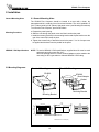
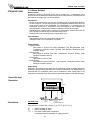
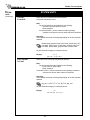
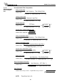
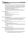
2.1 General Mounting Hints:
The SP4000 Flow Computer should be located in an area with a clean, dry
atmosphere which is relatively free of shock and vibration. The unit is installed in a
5.43" (138mm) wide by 2.68" (68mm) high panel cutout. (see Mounting Dimensions)
To mount the Flow Computer, proceed as follows:
Mounting Procedure
a. Prepare the panel opening.
b. Slide the unit through the panel cutout until the it touches the panel.
c. Install the screws (provided) in the mounting bracket and slip the bracket over the
rear of the case until it snaps in place.
d. Tighten the screws firmly to attach the bezel to the panel. 3 in. lb. of torque must
be applied and the bezel must be parallel to the panel.
NEMA4X / IP65 Specifications
NOTE: To seal to NEMA4X / IP65 specifications, supplied bezel kit must be used
and panel cannot flex more than .010".
When the optional bezel kit is used, the bezel adaptor must be sealed to the
case using an RTV type sealer to maintain NEMA4X / IP65 rating.
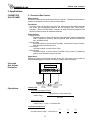
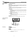
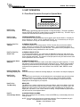
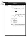
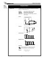
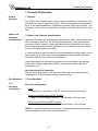
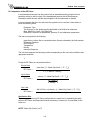
2.2 Mounting Diagrams:
Bezel Kit Mounting
Standard Mounting
SP4000
SP4000
Bezel Adaptor
Gasket
Mounting Bracket
Mounting Bracket
Dimensions
5.67 (144)
0.28 (7.2)
3.43
(87)
RATE
147.43 GPM
TOTAL 267395.749 GAL
START
STOP
TOTAL
1
RATE
2
PRE 1
3
TEMP
4
GRAND
6
SCROLL
7
PRE 2
8
DENS
9
PRINT
5
TIME
0
–
CLEAR
MENU
HELP
•
ENTER
6.15
(156)
0.4 (10)
Dotted Line Shows Optional Bezel Kit
Dimensions are in inches (mm)
10
5.43
(138)
Panel
Cutout
2.83
(72)
6.18
0.5
(13)
2.68
(68)
SP4000 Flow Computer
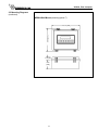
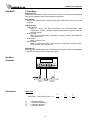
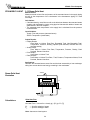
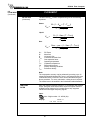
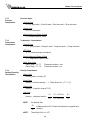
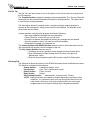
2.2 Mounting Diagrams:
(continued)
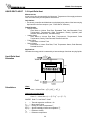
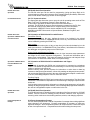
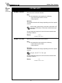
NEMA4 Wall Mount (mounting option F)
9.86 (250)
12.97 (329)
1.75 (44)
5.13
(130)
11
SP4000 Flow Computer
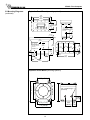
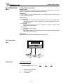
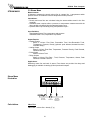
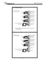
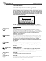
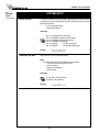
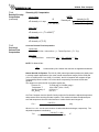
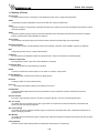
Explosion Proof Mount (mounting option X)
12.06
(306.3)
9.31
(236.5)
5.1
(129.5)
3.81 6.56
(96.8) (166.6)
1/4" - 20UNC-2B
TAP x 5/16" DEEP
(6) HOLES CENTERED
ON THREE SIDES FOR
MOUNTING
.28 ±.02
(7.1 ±.5)
3.5
(88.9)
3
(76.2)
1.31
(33.3)
2.13
(54)
10.6
(269.2)
1/4" - 20UNC-2B
TAP x 5/16" DEEP
(6) HOLES CENTERED
ON THREE SIDES FOR
MOUNTING
8.88
(225.5)
3.5
(88.9)
3.13
(79.4)
1/2"- 14 NPT PLUGS
(2 PLACES)
3
(76.2)
4.63
(117.5)
3.13
(79.4)
3.0
(76.2)
1.75
(44.5)
.5
(12.7)
.5
(12.7)
2.5
(63.5)
5.09
(129)
2.5
(63.5)
.25
(6.35)
10.19
(258.8)
10.19
(258.8)
Explosion Proof Mount (mounting option E)
11.5 (292.1)
7.75 (196.9)
9.125 (231.8)
6.25 (158.8)
10.5 (266.7)
2.2 Mounting Diagrams:
(continued)
1/2" - 14 NPT Plugs
(2 Places)
2.25
(57.2)
6.75 (171.5)
7.75 (196.9)
12
3.25 2.25
(82.6) (57.2)
SP4000 Flow Computer
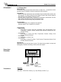
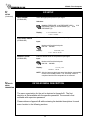
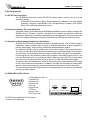
3. Applications
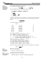
CORRECTED
GAS VOLUME
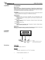
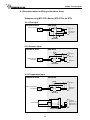
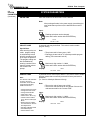
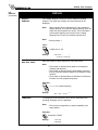
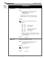
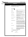
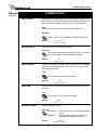
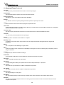
3.1 Corrected Gas Volume
Measurements:
A flowmeter measures the actual volume flow in a gas line. Temperature and pressure
sensors are installed to correct for gas expansion effects.
Calculations:
• Corrected Volume is calculated using the flow, temperature and pressure inputs as
well as the gas characteristics stored in the flow computer (see "FLUID DATA"
submenu). Use the "OTHER INPUT" submenu to define reference temperature and
reference pressure values for standard conditions.
Output Results:
• Display Results
Corrected Volume or Actual Volume Flow Rate, Resettable Total, Non-Resettable
Total, Temperature, Pressure, Density (optional: peak demand, demand last
hour, time/date stamp)
• Analog Output
Corrected Volume or Actual Volume Flow Rate, Temperature, Pressure, Density,
Peak Demand, Demand Last Hour
• Pulse Output
Corrected Volume or Actual Volume Total
• Relay Outputs
Corrected Volume or Actual Volume Flow Rate, Total, pressure, Temperature
Alarms, Peak Demand, Demand Last Hour
Applications:
Monitoring corrected volume flow and total of any gas. Flow alarms are provided via
relays and datalogging is available via analog (4-20mA) and serial outputs.
Corrected
Gas Volume
Illustration
Calculations
Volume Flow
TOTAL
1
RATE
2
PRE 1
3
TEMP
4
GRAND
6
SCROLL
7
PRE 2
8
DENS
9
Pressure
Transmitter
Flowmeter
PRINT
5
TIME
0
–
CLEAR
MENU
HELP
•
ENTER
Temperature
Transmitter
Pulse Input; Average K-Factor
input frequency • time scale factor
Volume Flow =
K-Factor
Analog Input; Linear
Volume Flow = % input • Full Scale Flow
Corrected Volume Flow
P
Corrected Volume Flow = Volume Flow •
•
Pref
13
Tref
T
•
Zref
Z
SP4000 Flow Computer
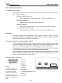
GAS MASS
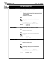
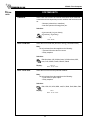
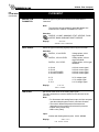
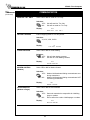
3.2 Gas Mass
Measurements:
A flowmeter measures the actual volume flow in a gas line. Temperature and pressure
sensors are installed to measure temperature and pressure.
Calculations:
• Density and mass flow are calculated using gas characteristics stored in the flow
computer.
Output Results:
• Display Results
Mass or Volume Flow Rate, Resettable Total, Non-Resettable Total,
Temperature, Pressure, Density (optional: peak demand, demand last hour,
time/date stamp)
• Analog Output
Mass or Volume Flow Rate, Temperature, Pressure, Density, Peak Demand,
Demand Last Hour
• Pulse Output
Mass or Volume Total
• Relay Outputs
Mass or Volume Flow Rate, Total, Pressure, Temperature, Density Alarms,
Peak Demand, Demand Last Hour
Applications:
Monitoring mass flow and total of gas. Flow alarms are provided via relays and datalogging
is available via analog (4-20mA) and serial outputs.
Gas Mass
Illustration
TOTAL
1
RATE
2
PRE 1
3
TEMP
4
GRAND
6
SCROLL
7
PRE 2
8
DENS
9
Pressure
Transmitter
Calculations
Flowmeter
PRINT
5
TIME
0
–
CLEAR
MENU
HELP
•
ENTER
Temperature
Transmitter
Mass Flow
Mass Flow = Actual Volume Flow • ρref •
ρref
Tref
Pref
Zref
=
=
=
=
Reference density
Reference temperature
Reference pressure
Reference Z-factor
14
P
•
Pref
Tref
T
•
Zref
Z
SP4000 Flow Computer
GAS COMBUSTION
HEAT
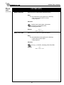
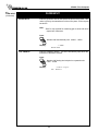
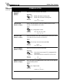
3.3 Gas Combustion Heat
Measurements:
A flowmeter measures the actual volume flow in a gas line. Temperature and pressure
sensors are installed to measure temperature and pressure.
Calculations:
• Density, mass flow and combustion heat are calculated using gas characteristics
stored in the flow computer.
Output Results:
• Display Results
Heat, Mass or Volume Flow Rate, Resettable Total, Non-Resettable Total,
Temperature, Pressure, Density (optional: peak demand, demand last hour,
time/date stamp)
• Analog Output
Heat, Mass or Volume Flow Rate, Temperature, Pressure, Density, Peak
Demand, Demand Last Hour
• Pulse Output
Heat, Mass or Volume Total
• Relay Outputs
Heat, Mass or Volume Flow Rate, Total, Pressure, Temperature Alarms, Peak
Demand, Demand Last Hour
Applications:
Calculate the energy released by combustion of gaseous fuels.
Gas Combustion
Heat
TOTAL
1
RATE
2
PRE 1
3
TEMP
4
GRAND
6
SCROLL
7
PRE 2
8
DENS
9
Pressure
Transmitter
Calculations
Flowmeter
PRINT
5
TIME
0
–
CLEAR
MENU
HELP
•
ENTER
Temperature
Transmitter
Combustion Heat Flow
Combustion Energy = C • ρref • Q •
C
ρref
Q
= Specific combustion heat
= Reference density
= Volume flow
15
P
•
Pref
Tref
T
•
Zref
Z
SP4000 Flow Computer
Corrected
Liquid Volume
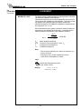
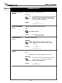
3.4 Corrected Liquid Volume
Measurements:
A flowmeter measures the actual volume flow in a liquid line. A temperature sensor is
installed to correct for liquid thermal expansion. A pressure sensor can be installed to
monitor pressure. Pressure measurement does not affect the calculation.
Calculations:
• Corrected Volume is calculated using the flow and temperature inputs as well as the
thermal expansion coefficient stored in the flow computer (see "FLUID DATA"
submenu). Use the "OTHER INPUT" submenu to define reference temperature and
density values for standard conditions.
Output Results:
• Display Results
Corrected Volume and Actual Volume Flow Rate, Resettable Total, NonResettable Total, Temperature, Pressure, Density (optional: peak demand,
demand last hour, time/date stamp)
• Analog Output
Corrected Volume and Actual Volume Flow Rate, Temperature, Pressure,
Density, Peak Demand, Demand Last Hour
• Pulse Output
Corrected Volume and Actual Volume Total
• Relay Outputs
Corrected Volume and Actual Volume Flow Rate , Total, Pressure, Temperature
Alarms, Peak Demand, Demand Last Hour
Applications:
Monitoring corrected volume flow and total of any liquid. Flow alarms are provided via
relays and datalogging is available via analog (4-20mA) and serial outputs.
Corrected
Liquid Volume
Illustration
TOTAL
1
RATE
2
PRE 1
3
TEMP
4
GRAND
6
SCROLL
7
PRE 2
8
DENS
9
Flowmeter
Calculations
Optional
Pressure
Transmitter
PRINT
5
TIME
0
–
CLEAR
MENU
HELP
•
ENTER
Temperature
Transmitter
Volume Flow
Pulse Input; Average K-Factor
input frequency • time scale factor
Volume Flow =
K-Factor
Analog Input; Linear
Volume Flow = % input • Full Scale Flow
Corrected Volume Flow
Corrected Volume Flow = vol. flow • (1 - α • (Tf-Tref))2
α
= Thermal expansion coefficient • 10-6
16
SP4000 Flow Computer
Liquid Mass
3.5 Liquid Mass
Measurements:
Actual volume flow is measured by the flowmeter. Temperature is measured by the
temperature transmitter. A pressure transmitter can be used to monitor pressure. Pressure
measurement does not affect the calculation. A density transmitter may be used in place
of a temperature transmitter for direct density measurement.
Calculations:
• The density and mass flow are calculated using the reference density and the thermal
expansion coefficient of the liquid (see "FLUID DATA" submenu)
Output Results:
• Display Results
Mass or Volume Flow Rate, Resettable Total, Non-Resettable Total,
Temperature, Pressure, Density (optional: peak demand, demand last hour,
time/date stamp)
• Analog Output
Mass or Volume Flow Rate, Temperature, Pressure, Density, Peak Demand,
Demand Last Hour
• Pulse Output
Mass or Volume Total
• Relay Outputs
Mass or Volume Flow Rate, Total, Temperature, Pressure, Density Alarms,
Peak Demand, Demand Last Hour
Applications:
Monitoring mass flow and total of any liquid. Flow alarms are provided via relays and
datalogging is available via analog (4-20mA) and serial outputs.
Liquid Mass
Illustration
TOTAL
1
RATE
2
PRE 1
3
TEMP
4
GRAND
6
SCROLL
7
PRE 2
8
DENS
9
Flowmeter
Calculations
Optional
Pressure
Transmitter
PRINT
5
TIME
0
–
CLEAR
MENU
HELP
•
ENTER
Temperature
Transmitter
T1
NOTE:
A density transmitter may be used
for direct density measurement.
Volume Flow
As calculated in section 3.4
Mass Flow
Mass Flow = volume flow • (1-a • (T1-Tref))2 • ref. density
α
= Thermal expansion coefficient • 10-6
17
SP4000 Flow Computer
LIQUID COMBUSTION 3.6 Liquid Combustion Heat
HEAT
Measurements:
Actual volume flow is measured by the flowmeter. Temperature is measured by the
temperature transmitter. A pressure transmitter can be used to monitor pressure. Pressure
measurement does not affect the calculation.
Calculations:
• The density, mass flow and combustion heat are calculated using the fluid
characteristics stored in the flow computer. (see "FLUID DATA" submenu)
Output Results:
• Display Results
Combustion Heat, Mass or Volume Flow Rate, Resettable Total, Non-Resettable
Total, Temperature, Pressure, Density (optional: peak demand, demand last
hour, time/date stamp)
• Analog Output
Combustion Heat, Mass or Volume Flow Rate, Temperature, Pressure, Density,
Peak Demand, Demand Last Hour
• Pulse Output
Combustion Heat, Mass or Volume Total
• Relay Outputs
Combustion Heat, Mass or Volume Flow Rate, Total, Temperature, Pressure
Alarms, Peak Demand, Demand Last Hour
Applications:
Calculate the energy released by combustion of liquid fuels
Liquid Combustion
Heat Illustration
TOTAL
1
RATE
2
PRE 1
3
TEMP
4
GRAND
6
SCROLL
7
PRE 2
8
DENS
9
Flowmeter
Calculations
Optional
Pressure
Transmitter
PRINT
5
TIME
0
–
CLEAR
MENU
HELP
•
ENTER
Temperature
Transmitter
T1
Volume Flow
As calculated in section 3.4
Heat Flow
Heat Flow = C • volume flow • (1-α • (T1-Tref))2 • ref. density
α
C
= Thermal expansion coefficient • 10-6
= Specific combustion heat
18
SP4000 Flow Computer
LIQUID SENSIBLE
HEAT
3.7 Liquid Sensible Heat
Measurements:
Actual volume flow is measured by the flowmeter. Temperature is measured by the
temperature transmitter. A pressure transmitter can be used to monitor pressure. Pressure
measurement does not affect the calculation.
Calculations:
• The density, mass flow and sensible heat are calculated using the fluid characteristics
stored in the flow computer. (see "FLUID DATA" submenu)
Output Results:
• Display Results
Sensible Heat, Mass or Volume Flow Rate, Resettable Total, Non-Resettable
Total, Temperature, Pressure, Density (optional: peak demand, demand last
hour, time/date stamp)
• Analog Output
Sensible Heat, Mass or Volume Flow Rate, Temperature, Pressure, Density,
Peak Demand, Demand Last Hour
• Pulse Output
Sensible Heat, Mass or Volume Total
• Relay Outputs
Sensible Heat, Mass or Volume Flow Rate, Total, Temperature, Pressure Alarms,
Peak Demand, Demand Last Hour
Applications:
Calculate the energy stored in a condensate with respect to water at 32°F (0°C).
Liquid Sensible Heat
Illustration
TOTAL
1
RATE
2
PRE 1
3
TEMP
4
GRAND
6
SCROLL
7
PRE 2
8
DENS
9
Flowmeter
Calculations
Optional
Pressure
Transmitter
PRINT
5
TIME
0
–
CLEAR
MENU
HELP
•
ENTER
Temperature
Transmitter
T1
Volume Flow
As calculated in section 3.4
Heat Flow
Heat Flow = C • volume flow • (1-α • (T1-Tref))2 • ref. density • (T1 - 32)
α
C
= Thermal expansion coefficient • 10-6
= Specific heat
19
SP4000 Flow Computer
LIQUID DELTA HEAT
3.8 Liquid Delta Heat
Measurements:
Actual volume flow is measured by the flowmeter. Temperature of the supply and return
lines are measured by the temperature transmitters.
Calculations:
• The density, mass flow and delta heat are calculated using values of the heat carrying
liquid stored in the flow computer. (see "FLUID DATA" submenu)
Output Results:
• Display Results
Heat, Mass or Volume Flow Rate, Resettable Total, Non-Resettable Total,
Temperature1, Temperature2, Delta Temperature, Density, (optional: peak
demand, demand last hour, time/date stamp)
• Analog Output
Heat, Mass or Volume Flow Rate, Temperature1, Temperature2, Delta
Temperature, Density, Peak Demand, Demand Last Hour
• Pulse Output
Heat, Mass or Volume Total
• Relay Outputs
Heat, Mass or Volume Flow Rate, Total, Temperature Alarms, Peak Demand,
Demand Last Hour
Applications:
Calculate the energy which is extracted by a heat exchanger from heat carrying liquids.
T2
Temperature
Transmitter
Liquid Delta Heat
Illustration
Warm
Water
TOTAL
1
RATE
2
PRE 1
3
TEMP
4
GRAND
6
SCROLL
7
PRE 2
8
DENS
9
PRINT
5
TIME
0
–
CLEAR
MENU
HELP
•
ENTER
Cold
Flowmeter
Calculations
T1
Temperature
Transmitter
Water
Heat = Volume Flow • ρ(T1) • [h(T2) – h(T1)]
Other heat carrying liquids
Heat = C • volume flow • (1-α • (T1-Tref))2 • ρref • (T2 - T1)
WHERE: Delta T > Low Delta T Cutoff
α
C
ρ(T1)
h(T1)
h(T2)
ρref
Tref
=
=
=
=
=
=
=
Thermal expansion coefficient • 10-6
Mean specific heat
Density of water at temperature T1
Specific enthalpy of water at temperature T1
Specific enthalpy of water at temperature T2
Reference density
Reference temperature
20
SP4000 Flow Computer
STEAM MASS
3.9 Steam Mass
Measurements:
A flowmeter measures the actual volume flow in a steam line. A temperature and/or
pressure sensor is installed to measure temperature and/or pressure.
Calculations:
• Density and mass flow are calculated using the steam tables stored in the flow
computer.
• Saturated steam requires either a pressure or temperature measurement with the
other variable calculated using the saturated steam curve.
• Optional steam trap monitoring using Compensation Input 1.
Input Variables:
Superheated Steam: Flow, temperature and pressure
Saturated Steam: Flow, temperature or pressure
Output Results:
• Display Results
Mass or Volume Flow Rate, Resettable Total, Non-Resettable Total,
Temperature, Pressure, Density (optional: peak demand, demand last hour,
time/date stamp)
• Analog Output
Mass or Volume Flow Rate, Temperature, Pressure Density, Peak Demand,
Demand Last Hour
• Pulse Output
Mass or Volume Total
• Relay Outputs
Mass or Volume Flow Rate , Total, Pressure, Temperature, Alarms, Peak
Demand, Demand Last Hour
Applications:
Monitoring mass flow and total of steam. Flow alarms are provided via relays and
datalogging is available via analog (4-20mA) and serial outputs.
Steam Mass
Illustration
TOTAL
1
RATE
2
PRE 1
3
TEMP
4
GRAND
6
SCROLL
7
PRE 2
8
DENS
9
Pressure
Transmitter
Calculations
714
Flowmeter
PRINT
5
TIME
0
CLEAR
MENU
HELP
•
ENTER
Condulet
Temperature
Transmitter
Mass Flow
Mass Flow = volume flow • density (T, p)
21
–
SP4000 Flow Computer
STEAM HEAT
3.10 Steam Heat
Measurements:
A flowmeter measures the actual volume flow in a steam line. A temperature and/or
pressure sensor is installed to measure temperature and/or pressure.
Calculations:
• Density, mass flow and heat flow are calculated using the steam tables stored in the
flow computer. The heat is defined as the enthalpy of steam under actual conditions
with reference to the enthalpy of water at T=0°C.
• Saturated steam requires either a pressure or temperature measurement with the
other variable calculated using the saturated steam curve.
• Optional steam trap monitoring using compensation input.
Input Variables:
Superheated Steam: Flow, temperature and pressure
Saturated Steam: Flow, temperature or pressure
Output Results:
• Display Results
Heat, Mass or Volume Flow Rate, Resettable Total, Non-Resettable Total,
Temperature, Pressure, Density (optional: peak demand, demand last hour,
time/date stamp)
• Analog Output
Heat, Mass or Volume Flow Rate, Temperature, Pressure, Density, Peak
Demand, Demand Last Hour
• Pulse Output
Heat, Mass or Volume Total
• Relay Outputs
Heat, Mass or Volume Flow Rate , Total, Pressure, Temperature Alarms, Peak
Demand, Demand Last Hour
Applications:
Monitoring heat flow and total heat of steam. Flow alarms are provided via relays and
datalogging is available via analog (4-20mA) and serial outputs.
Steam Heat
Illustration
TOTAL
1
RATE
2
PRE 1
3
TEMP
4
GRAND
6
SCROLL
7
PRE 2
8
DENS
9
Pressure
Transmitter
Flowmeter
PRINT
5
TIME
0
–
CLEAR
MENU
HELP
•
ENTER
Temperature *
Transmitter
* or Steam Trap Monitor
Calculations
Heat Flow
Heat Flow = Volume flow • density (T, p) • Sp. Enthalpy of steam (T, p)
22
SP4000 Flow Computer
STEAM NET HEAT
3.11 Steam Net Heat
Measurements:
A flowmeter measures the actual volume flow in a steam line. A temperature and a
pressure sensor are installed to measure temperature and/or pressure. All measurements
are made on the steam side of a heat exchanger.
Calculations:
• Density, mass flow and net heat flow are calculated using the steam tables stored in
the flow computer. The net heat is defined as the difference between the heat of the
steam and the heat of the condensate. For simplification it is assumed that the
condensate (water) has a temperature which corresponds to the temperature of
saturated steam at the pressure measured upstream of the heat exchanger.
• Saturated steam requires either a pressure or temperature measurement with the
other variable calculated using the saturated steam curve.
• Optional steam trap monitoring using compensation input.
Input Variables:
Superheated Steam: Flow, temperature and pressure
Saturated Steam: Flow, temperature or pressure
Output Results:
• Display Results
Heat, Mass or Volume Flow Rate, Resettable Total, Non-Resettable Total,
Temperature, Pressure, Density, (optional: peak demand, demand last hour,
time/date stamp)
• Analog Output
Heat, Mass or Volume Flow Rate, Temperature, Pressure, Density, Peak
Demand, Demand Last Hour
• Pulse Output
Heat, Mass or Volume Total
• Relay Outputs
Heat, Mass or Volume Flow Rate , Total, Pressure, Temperature Alarms, Peak
Demand, Demand Last Hour
Applications:
Monitoring the thermal energy which can be extracted by a heat exchanger taking into
account the thermal energy remaining in the returned condensate. For simplification it is
assumed that the condensate (water) has a temperature which corresponds to the
temperature of saturated steam at the pressure measured upstream of the heat exchanger.
Steam Net Heat
Illustration
Water
TOTAL
1
RATE
2
PRE 1
3
TEMP
4
GRAND
6
SCROLL
7
PRE 2
8
DENS
9
PRINT
5
TIME
0
–
CLEAR
MENU
HELP
•
ENTER
Steam
Calculations
Net Heat Flow
Pressure
Transmitter
Flowmeter Temperature
Transmitter
*
* or Steam Trap Monitor
Net Heat Flow = Volume flow • density (T, p) • [ED (T, p)– EW (TS(p))]
ED
Ew
TS(p)
= Specific enthalpy of steam
= Specific enthalpy of water
= Calculated condensation temperature
(= saturated steam temperature for supply pressure)
23
SP4000 Flow Computer
STEAM DELTA HEAT
3.12 Steam Delta Heat
Measurements:
Measures actual volume flow and pressure of the saturated steam in the supply piping
as well as the temperature of the condensate in the downstream piping of a heat
exchanger.
Calculations:
• Calculates density, mass flow as well as the delta heat between the saturated steam
(supply) and condensation (return) using physical characteristic tables of steam and
water stored in the flow computer.
• The saturated steam temperature in the supply line is calculated from the pressure
measured there.
Input Variables:
Supply: Flow and pressure (saturated steam)
Return: Temperature (condensate)
Output Results:
• Display Results
Heat, Mass or Volume Flow Rate, Resettable Total, Non-Resettable Total,
Temperature, Pressure, Density (optional: peak demand, demand last hour,
time/date stamp)
• Analog Output
Heat, Mass or Volume Flow Rate, Temperature, Pressure, Density, Peak
Demand, Demand Last Hour
• Pulse Output
Heat, Mass or Volume Total
• Relay Outputs
Heat, Mass or Volume Flow Rate , Total, Pressure, Temperature Alarms, Peak
Demand, Demand Last Hour
Applications:
Calculate the saturated steam mass flow and the heat extracted by a heat exchanger
taking into account the thermal energy remaining in the condensate.
Temperature
Transmitter
Steam Delta Heat
Illustration
Water
TOTAL
1
RATE
2
PRE 1
3
TEMP
4
GRAND
6
SCROLL
7
PRE 2
8
DENS
9
PRINT
5
TIME
0
–
CLEAR
MENU
HELP
•
ENTER
Saturated
Steam
Pressure
Transmitter
Calculations
Flowmeter
Delta Heat Flow
Net Heat Flow = Volume flow • density (p) • [ED (p)– EW (T)]
ED
Ew
= Specific enthalpy of steam
= Specific enthalpy of water
Note: Assumes a closed system.
24
SP4000 Flow Computer
4. WIRING
4.1 Terminal Designations
Two Relay Terminations
1
2
3
4
5
6
7
8
9
10
11
12
13
14
15
16
17
18
19
20
21
22
Three Relay Option Terminations
DC OUTPUT
PRESSURE
RTD EXCIT (+)
(TEMP 2)
RTD SENS (+)
IN
Iin (+)
RTD SENS (-)
PULSE OUTPUT (+)
PULSE OUTPUT (-)
ANALOG OUTPUT 1 (+)
ANALOG OUTPUT 2 (+)
ANALOG OUTPUT COMMON (-)
1
2
3
4
5
6
7
8
9
10
11
12
13
14
15
16
DC OUTPUT
PRESSURE
RTD EXCIT (+)
(TEMP 2)
RTD SENS (+)
IN
Iin (+)
RTD SENS (-)
PULSE OUTPUT (+)
PULSE OUTPUT (-)
ANALOG OUTPUT 1 (+)
ANALOG OUTPUT 2 (+)
ANALOG OUTPUT COMMON (-)
NO
COM RLY1
NC
NC
COM RLY2
NO
17
18
19
20
21
22
N.O. RLY1
COM. RLY1
N.O. RLY3
COM. RLY3
N.O. RLY2
COM. RLY2
DC OUTPUT
PULSE IN
---------COMMON
RTD EXCIT (+)
RTD SENS (+)
RTD SENS (-)
23 AC LINE
24 AC LINE
FLOW
IN
Vin (+)
Iin (+)
TEMPERATURE
IN
Iin (+)
DC (+)
DC (-)
**
POWER IN
DC OUTPUT
PULSE IN
---------COMMON
RTD EXCIT (+)
RTD SENS (+)
RTD SENS (-)
23 AC LINE
24 AC LINE
**In trap monitor mode, terminal 7 is used for Iin (+) from trap monitor.
25
Vin (+)
Iin (+)
FLOW
IN
TEMPERATURE
IN
Iin (+)
DC (+)
DC (-)
**
POWER IN
SP4000 Flow Computer
4.2 Typical Wiring Connections:
4.2.1 Flow Input
3-30 VDC Pulses
(i.e. SP714, SP717 Flowmeter)
10 mV Signal
(i.e. Turbine Flowmeter
with Magnetic Pickup)
Analog 4-20 mA Transmitter
(i.e. F/I Converter,
SP712, SP720-2)
Analog Voltage Transmitter
(i.e. Turbine Flowmeter
with F/V Converter, SP711-3)
+
Pulse
3-30 V –
Mag
10 mV –
+
4-20
mA
–
+
0-5
VDC
–
1
2
3
4
1
2
3
4
1
2
3
1
2
3
4
(+) 24 V Out
Pulse In
Common
Pulse In
Common
(+) 24 V Out
4-20 mA In
(+) V In
Common
4.2.2 Pressure Input
4-20 mA Pressure
Transmitter
26
+
4-20
mA
–
8
9
10
11
(+) 24 V Out
4-20 mA In
SP4000 Flow Computer
4.2.3 Temperature Input
RTD Connections
2, 3 & 4 wire RTD's
2-Wire
RTD
5 RTD Excitation (+)
6 RTD Sense (+)
7 RTD Sense (–)
3-Wire
RTD
5 RTD Excitation (+)
6 RTD Sense (+)
7 RTD Sense (–)
4-Wire
RTD
5 RTD Excitation (+)
6 RTD Sense (+)
7 RTD Sense (–)
–
4-20 mA Temperature
Transmitter
4-20
mA
*
+
7 4-20 mA In
8 (+) 24 V Out
* Or optional steam trap monitoring input in some saturated
steam applications.
4.2.4 Temperature 2 Input
RTD Connections
2, 3 & 4 wire RTD's
2-Wire
RTD
9 RTD Excitation (+)
10 RTD Sense (+)
11 RTD Sense (–)
3-Wire
RTD
9 RTD Excitation (+)
10 RTD Sense (+)
11 RTD Sense (–)
4-Wire
RTD
9 RTD Excitation (+)
10 RTD Sense (+)
11 RTD Sense (–)
+
4-20 mA Temperature
Transmitter
4-20
mA
27
–
8 (+) 24 V Out
9
10
11 4-20 mA In
SP4000 Flow Computer
4.3 Recommendation for Wiring In Hazardous Areas
Examples using MTL787S+ Barrier (MTL4755ac for RTD)
4.3.1 Flow Input
Hazardous Area
Q/∆P
3 4
4-20 +
SP712, SP720-2
–
28V
Diode
2 1
Safe Area
1
2
3
4
24V Out
4-20mA In
Common
MTL787S+
4.3.2 Pressure Input
Hazardous Area
Safe Area
4-20 +
P
3 4
4-20mA Pressure
Transmitter
–
28V
Diode
2 1
4 Common
8 24V Out
9
10
11 4-20mA In
MTL787S+
4-20 –
T
4 3
4-20mA Temperature
Transmitter
Safe Area
+
28V
Diode
1 2
4.3.3 Temperature Input
Hazardous Area
4 Common
5
6
7 4-20mA In
8 24V Out
1
2
3
3-Wire RTD
MTL4755ac
28
7 8 9 10 11 12 13 14 15 16 17
4
5
6
MTL787S+
4
5
6
7
8
Common
RTD Excit (+)
RTD Sens (+)
RTD Sens (–)
SP4000 Flow Computer
5. UNIT OPERATION
5.1 Front Panel Operation Concept for Operate Mode
RATE
147.43 GPM
TOTAL 267395.749 GAL
TOTAL
1
RATE
2
GRAND
6
SCROLL
7
ALARM 1
3
TEMP
4
PRINT
5
ALARM 2
8
PRES
9
TIME
0
–
CLEAR
MENU
HELP
•
ENTER
How To Use
On-Line Help
HELP
On-line help is provided to assist the operator in using this product. The help is available
during OPERATE and SETUP modes simply by pressing the HELP key. The HELP key is
used to enter decimals when entering numeric values.
How To View
Process Values
VIEWING PROCESS VALUES
In the OPERATE mode, several keys have a special, direct access feature, to display an
item of interest (i.e. RATE, TOTAL, ALARM SETPOINT, etc.). Press the key to view your
choice. Press the ∆ ∇ keys to view other items in that group.
How To Clear The
Totalizer
CLEARING TOTALIZER
To clear the totalizers, you must press the TOTAL Function Key to select the totalizer
group. Press the ∆ ∇ keys to select the desired totalizer. Once the desired totalizer is
displayed, press the CLEAR key to reset the total. The operator will be prompted to verify
this action and to enter a password if the unit is locked.
How To Clear The
Grand Total
CLEARING GRAND TOTAL
To clear the grand totalizers, you must press the GRAND Function Key and use the ∆ ∇
keys to select the desired grand total. Once the grand total is selected, press the CLEAR
key to reset the grand total. The operator will be prompted to verify this action and to enter
service password if the unit is locked.
How To Enter Alarm
Setpoints
ALARM SETPOINT KEYS
ALARM 1 & ALARM 2 keys are used to view and/or change the alarm setpoints. To view
the setpoints, simply press the desired Alarm setpoint key once. Rapidly press the alarm
setpoint keys several times for direct editing of the alarm setpoints. The operator will be
prompted to enter password if the unit is locked. Press CLEAR, "###", ENTER to enter
value.
How To Activate The
Scrolling Display List
SCROLL
Press the Scroll key to activate the scrolling display list. See section 6 to setup the display list.
How To Use
The Print Key
PRINT
The PRINT key is used to print on demand when the communication port is set for printer.
When the PRINT key is pressed, a user defined list of data (TOTAL, RATE, ALARM
SETPOINT, etc.) is sent to the RS-232 port. A timed message of "PRINTING" will be
displayed to acknowledge the print request.
How To Use
The Menu Key
MENU KEY
The MENU key is used to view/enter the Instrument Setup and Service Mode. Press the
MENU key to access the Setup and Service modes. (See section 6 for Setup mode). The
MENU key is also used for a "Pop-Back" function. When the MENU key is pressed, the
display will "Pop-Back" to the current submenu heading. Multiple MENU key depressions
will return the unit to the Operate Mode.
How To
Acknowledge Alarms
ACKNOWLEDGING ALARMS
Most alarm messages are self-clearing. Press the ENTER key to acknowledge and clear
latching alarms.
NOTE: Some keys and functions are password protected. Enter the password to gain
access. The passwords are factory set as follows:
Private = 1000, Service = 2000
29
SP4000 Flow Computer
General
Operation
5.2 General Operation
This instrument is used primarily to monitor flowrate and accumulated total. The inputs
can be software configured for a variety of flowmeter, temperature and pressure sensors.
The standard output types include: Pulse, Relay, Analog and RS-232 The unit can
display the flowrate, total and process variables. RS-485 is an available option for a
second communication channel.
Password Protection
5.3 Password Protection
After an Private and/or Service Code is entered in the "System Parameters" Submenu
Group. (see section 6.3, Private Code and Service Code sub-menus), the unit will be
locked. The unit will prompt the user for the password when trying to perform the
following functions:
Clear Totals
Clear Grand Totals (service code required)
Edit a Setup Menu Item
Edit Alarm Setpoints (ALARM 1 & ALARM 2 Keys)
The Service Code should be reserved for service technicians. The Service Code will
allow access to restricted areas of the Service and Test menus. Changes in these
areas may result in lost calibration information.
Relay Operation
5.4 Relay Operation
Two relay alarm outputs are standard. The relays may also be used for pulse outputs.
The relays can be assigned to trip according to various rate, total, temperature or
pressure readings. The relays can be programmed for low/high alarms, latch or unlatch,
or as relay pulse outputs.
ALARM SETPOINT 1 (RLY1) and ALARM SETPOINT 2 (RLY2) are easily accessible
by pressing the ALARM 1 or ALARM 2 key on the front panel.
Pulse Output
5.5 Pulse Output
The isolated pulse output is menu assignable to any of the available totals. The pulse
output duration and scaling can be set by the user. The pulse output is ideal for
connecting to remote totalizers or other devices such as a PLC. See section 1.2 for
electrical specifications.
Analog Outputs
5.6 Analog Outputs
The analog outputs are menu assignable to correspond to any of the process parameters.
The outputs are menu selectable for 0-20 mA or 4-20 mA. The analog outputs are ideal
for "trend" tracking using strip chart recorders or other devices.
Function Keys
Display Grouping
5.7 Function Keys; Display Grouping
TOTAL
Press the
to view HEAT TOTAL, MASS TOTAL, CORRECTED VOLUME
GRAND TOTAL
TOTAL, VOLUME TOTAL
Press the
to view GRAND HEAT, GRAND MASS, GRAND CORRECTED
RATE
VOLUME, GRAND VOLUME
Press the
to view HEAT, MASS , CORRECTED VOLUME, VOLUME,
TEMPERATURE
PEAK DEMAND, DEMAND LAST HOUR
Press the
to view TEMPERATURE 1, TEMPERATURE 2, DELTA
PRESSURE
TEMPERATURE, DENSITY
Press the
to view PRESSURE, DIFFERENTIAL PRESSURE, , Y1,
TIME
SPECIFIC ENTHALPY
Press the
to view TIME/DATE, PEAK TIME/DATE, ACCUMULATIVE
POWER LOSS TIME, TIME OF LAST POWER OUTAGE, TIME POWER
WAS LAST RESTORED
30
SP4000 Flow Computer
RS-232 Serial Port
Operation
5.8 RS-232 Serial Port Operation
The RS-232 serial port can be used for programming (using the Setup Disk) or for
communicating to printers and computers in the Operating Mode (Run Mode). Enhanced
uses include remote metering by modem or two way pager.
PC Communications
5.8.1 PC Communications:
The Setup Disk also allows the user to query the unit for operating status such as Flow
Rate, Flow Total, Temperature, Pressure, Alarm Setpoints, etc.
In this mode of operation the RS232 port is assumed connected to a
computer. The SP4000 will act as a slave and answer requests from the PC. See
the Universal Protocol Users Manual for a complete listing of the commands
set supported. A DDE/OPC Server is also available for use in exchanging
information with DDE Clients such as Spread Sheets, Database Programs, and
HMI software.
RS-232 Serial Port
Operation of RS-232 Serial
Port with Printers
5.8.2 Operation of RS-232 Serial Port with Printers:
Transaction Printing
For transaction printing, the user defines the items to be included in the printed
document (see section 6.13 COMMUNICATION, Print List). The transaction document
can be initiated by pressing the PRINT key.
Data Logging
The user can select when (time of day) or how often (print interval) the data log is to be
made (see section 6.13 COMMUNICATION, Print Initiate). Information will be stored to
the datalogger and optionally output to the RS-232 port.
System Setup and Maintenance Report
The system setup and maintenance report lists all of the instrument setup parameters
and usage for the current instrument configuration. The audit trail information and a
status report is also printed. This report is initiated in the Service and Analysis Group
(see section 6.15 SERVICE & ANALYSIS, Print System Setup).
Operation of RS-232 Serial
Port with Modems and
Pagers
5.8.3 Operation of RS-232 Serial Port with Modems and Pagers
Modem
In this mode of operation the RS232 port is assumed to be connected to a telephone
modem. The SP4000 is responsible for communicating to a remote computer through the
modem to perform such actions as:
Answer incoming calls, process requests for information or action items or data log
contents or change setup parameters, call out daily readings to designed phone number,
call out to designated phone number in the case of a designated exception or malfunction
in the unit, terminating telephone calls if a connection is lost.
Two Way Paging
In this mode of operation the RS232 port is assumed to be connected to a Two Way Pager
Transceiver. The SP4000 is responsible for communicating to the pager to perform such
actions as:
Look for and process requests for information or change setup parameters, call out daily
readings to designed pager/email address, call out to designated pager/email address in
the case of a designated exception or malfunction in the unit.
RS-485 Serial Port
Operation
5.9 RS-485 Serial Port Operation
The RS-485 serial port is intended to permit operation of the flow computer in a RS-485
network. Access is limited to reading process variables, totalizers, error logs and to
executing action routines such as clearing totalizers, alarms, and changing setpoints.
Pause Computations
Prompt
5.10 Pause Computations Prompt
The user will be prompted with a "Pause Computations" message when making significant
setup changes to the instrument. Pausing computations is necessary to make any
significant changes. With computations paused, all outputs assume a safe state equal
to that of an unpowered unit. Computations resume when exiting the setup menu.
31
SP4000 Flow Computer
6. PROGRAMMING
6.1 Front Panel Operation Concept for Program Mode
The SP4000 is fully programmable through the front panel. The instrument setup menu
structure is based on a number of topical submenu groups with one submenu group for
each instrument function. Each submenu contains all of the individual settings associated
with that function. During the instrument setup, setup topics are shown on the bottom
line of the display while the detailed selection options are shown on the top line. A help
menu is available for each menu item.
Please review the following key usage summary before attempting to setup the instrument.
TOTAL
1
RATE
2
PRE 1
3
TEMP
4
PRINT
5
GRAND
6
SCROLL
7
PRE 2
8
DENS
9
TIME
0
–
CLEAR
MENU
HELP
•
ENTER
CAUTION: When the computations are paused the instrument outputs will go to a
safe state which is the same as if the unit lost power. All calculations stop.
Key Usage Summary:
Menu Key
MENU KEY
Pressing the MENU key while in the "HOME" position will select the view setup
parameters mode. Thereafter, the MENU key is used to "pop up" one menu level (i.e.
return to the start of the submenu group). The unit will "pop up" one level for each time
the MENU key is pressed until finally returning to the "HOME" position of
showing the "scroll" display list.
Up & Down
Arrow Keys
UP & DOWN ARROW KEYS
Use the UP and DOWN arrow keys to navigate through the submenu groups. The up
and down arrow keys are also used to view the next/previous selection in a selection
list within a submenu cell. When entering text characters, the UP and DOWN arrow
keys are used to scroll through the available character sets for each individual
character location. Press the ENTER key to accept the character and advance to the
next character.
Help Key
HELP KEY
On-line help is available to assist the user during instrument setup. A quick help is
provided at each setup step. Press the HELP key to display a help message for the
current setup selection. This key is also used to enter decimals during numeric entry
sequences.
Numeric Entry
Keys
NUMERIC ENTRY KEYS
The keys labeled "0 - 9", "–", ".", CLEAR and ENTER are used to enter numerical
values. A leading 0 will assume that you intend to enter a minus "–" sign.
The standard numeric entry sequence is: CLEAR, "###", ENTER.Numeric entry values
are bounded or clamped by minimum and maximum permitted values.
CLEAR
Clear Key
CLEAR KEY
The CLEAR key is used to clear numeric values to "0".
ENTER
Enter Key
ENTER KEY
The ENTER key is used to accept the current value and advance to the next selection
(Successfully terminate the current numeric entry sequence).
MENU
HELP
•
0
–
9
32
SP4000 Flow Computer
6.2
EZ
SETUP
EZ SETUP
EZ SETUP
The EZ Setup routine is a quick and easy way to configure the most
commonly used instrument functions. We recommend first
completing the EZ Setup routine for the flow equation and meter
type for your initial application. The setup can then be customized
using the complete submenu groups described later in this chapter.
Caution:
Entering the EZ Setup mode automatically sets many
features to a default value (without prompting the user).
This may cause any previously programmed information to
be lost or reset.
Selection:
YES, NO
Display:
EZ Setup
Example:
Gas Corrected Volume
Turbine Flowmeter
UNITS
EZ SETUP?
YES
PAUSE COMPUTATIONS
Note:
The "Pause Computations" warning message informs the
user that all computations are halted while programming EZ
Setup.
Select the desired units of measure.
Selection:
METRIC, ENGLISH
Display:
FLOW EQUATION
ENGLISH
UNITS?
Select the flow equation appropriate for your application.
Selection:
STEAM MASS, STEAM HEAT, STEAM NET HEAT,
STEAM DELTA HEAT, GAS CORRECTED VOLUME, GAS
MASS, GAS COMBUSTION HEAT, LIQ.CORRECTED
VOLUME, LIQUID MASS, LIQ. COMBUSTION HEAT,
LIQUID SENSIBLE HEAT, LIQUID DELTA HEAT
Display:
33
GAS CORRECTED VOLUME
FLOW EQUATION
SP4000 Flow Computer
6.2
EZ
SETUP
(Continued)
EZ SETUP
FLUID TYPE
Select the type of fluid appropriate for your application.
Selection:
GENERIC, DRY AIR, NATURAL GAS, NATURAL GAS
(NX19), HUMID GAS, HUMID AIR, HYDROGEN, ARGON,
METHANE, NITROGEN, CARBON DIOXIDE, PROPANE,
OXYGEN, ETHANE, HELIUM
Display:
FLOWMETER TYPE
NITROGEN
FLUID TYPE
Select the flowmeter type used in your application.
Selection:
LINEAR, SQR LAW, SQR LAW-LIN., LINEAR 16 PT, SQR
LAW 16 PT, SQR LAW-LIN. 16 PT, LINEAR UVC, GILFLO,
GILFLO 16 PT, BYPASS
Display:
INPUT SIGNAL
LINEAR
FLOWMETER TYPE
Select the appropriate input signal.
Selection:
4-20 mA, 0-20 mA, 0-5 Vdc, 1-5 Vdc, 0-10 Vdc, DIGITAL:
10 mV LEVEL, DIGITAL: 100 mV LEVEL, DIGITAL: 2.5 V
LEVEL, 4-20mA STACKED, 0-20mA STACKED, 4-20mA
LINEAR MANIFOLD, 0-20mA LINEAR MANIFOLD
Display:
K-FACTOR
DIGITAL 2.5 V LEVEL
INPUT SIGNAL
Enter the K-Factor for the flowmeter.
Input:
TOTAL
1RATE
2
Number with floating decimal point:
0.0001...999999
Display:
INPUT SIGNAL
(TEMPERATURE)
123.67 P/ft3
K-FACTOR
Select the appropriate pressure input signal.
Selection:
MANUAL TEMPERATURE, 4-20 TEMPERATURE,
0-20 TEMPERATURE, RTD TEMPERATURE
Display:
4-20 PRESSURE (ABS.)
INPUT SIGNAL
34
SP4000 Flow Computer
6.2
EZ
SETUP
(Continued)
EZ SETUP
LOW SCALE VALUE
(TEMPERATURE)
Enter the full scale value for the pressure input signal.
Input:
TOTAL
1RATE
2
Number with fixed decimal point:
000.000 ... 999.999
Display:
FULL SCALE VALUE
(TEMPERATURE)
32.00 ° F
FULL SCALE VALUE
Enter the full scale value for the pressure input signal.
Input:
TOTAL
1RATE
2
Number with fixed decimal point:
000.000 ... 999.999
Display:
DEFAULT VALUE
(TEMPERATURE)
752.00 ° F
FULL SCALE VALUE
Enter the default value for the pressure input signal.
Input:
Number with fixed decimal point:
000.000 ... 999.999
Display:
35
70.00 ° F
DEFAULT VALUE
SP4000 Flow Computer
6.2
EZ
SETUP
(Continued)
EZ SETUP
INPUT SIGNAL
(PRESSURE)
Select the appropriate pressure input signal.
Selection:
TOTAL
1RATE
2
MANUAL PRESSURE, 4-20 PRESSURE (ABS.),
0-20
PRESSURE (ABS.), 4-20 PRESSURE (G),
0-20
PRESSURE (G)
Display:
FULL SCALE VALUE
(PRESSURE)
4-20 PRESSURE (ABS.)
INPUT SIGNAL
Enter the full scale value for the pressure input signal.
Input:
TOTAL
1RATE
2
Number with fixed decimal point:
000.000 ... 999.999
Display:
DEFAULT VALUE
(PRESSURE)
580.000 psia
FULL SCALE VALUE
Enter the default value for the pressure input signal.
Input:
TOTAL
1RATE
2
Number with fixed decimal point:
000.000 ... 999.999
Display:
14.696 psia
DEFAULT VALUE
NOTE: After the last entry has been saved, the display automatically
returns to the HOME position. The “EZ Setup” routine is
completed and the flow computations are resumed.
6.3
DETAILED
MENU
DESCRIPTION
DETAILED MENU DESCRIPTION
The menu organization for the unit is depicted in Appendix B. The first
depiction is that available with the operator password. The second is that
available with supervisor password.
Please reference Appendix B while reviewing the detailed descriptions for each
menu location in the following sections.
36
SP4000 Flow Computer
6.4
SYSTEM
PARAMETERS
SYSTEM PARAMETERS
EZ SETUP
The EZ Setup routine is a quick and easy way to
configure the most commonly used instrument functions.
Reference:
Refer to Section 6.2 for EZ Setup Programming.
Caution:
Entering the EZ Setup mode automatically sets
many features to default values without informing
the user. This may cause any previously
programmed information to be lost or reset
Selection:
YES, NO
Display:
EZ SETUP?
NO
PAUSE COMPUTATIONS
Note:
The "Pause Computations" warning message
informs the user that all computations are halted
while programming EZ Setup.
ACCESS CODE
This is the menu location where the operator can unlock
the unit by entering the correct password (operator or
supervisor code), or lock the unit by entering the incorrect
password.
Selection:
0 - 9999
Display:
37
0
ACCESS CODE
SP4000 Flow Computer
6.4
SYSTEM
PARAMETERS
(Continued)
SYSTEM PARAMETERS
FLOW EQUATION
The Flow Equation sets the basic functionality of the unit. Choose the
Flow Equation for your particular application.
Note:
Various setup data is only available depending on the flow
equation selected. The flow equation also determines the
assignment of the inputs.
Caution:
Select the flow equation as the first step. We recommend
using the EZ Setup to select the proper flow equation. The
user can then enter the submenu groups and make additional
changes as desired.
Selection:
GAS COMBUSTION HEAT, GAS MASS, GAS CORRECTED
VOLUME, STEAM DELTA HEAT, STEAM NET HEAT,
STEAM HEAT, STEAM MASS, LIQUID DELTA HEAT,
LIQUID SENSIBLE HEAT, LIQ. COMBUSTION HEAT,
LIQUID MASS, LIQ. CORRECTED VOLUME.
Display:
ENTER DATE
GAS CORRECTED VOLUME
FLOW EQUATION
Enter the date in this format: Day - Month - Year.
Note:
After prolonged breaks in the power supply (several days) or
upon initial start-up of the unit, the date and time must be
reset. This does not apply to units with the datalogger or
language option.
Input:
CLEAR
ENTER
Flashing selections can be changed.
Store and Confirm entries with the ENTER key
Display:
DAYLIGHT SAVINGS
TIME
08 FEB 1996
ENTER DATE
The "Daylight Savings" mode allows the unit to automatically adjust
the time according to daylight savings time change
Note:
Select "Yes" to enable the Daylight Savings Mode
Selection:
Yes, No
Display:
Yes
DAYLIGHT SAVINGS
38
SP4000 Flow Computer
6.4
SYSTEM
PARAMETERS
(Continued)
SYSTEM PARAMETERS
ENTER TIME
Enter the actual time in this format: Hours - Minutes
Note:
After prolonged breaks in the power supply (several days) or
upon initial start-up of the unit, the date and time must be
reset.
Input:
CLEAR
TOTAL
Flashing selections can be changed.
Store and Confirm entries with the ENTER key
1RATE
2
ENTER
Display:
PRIVATE CODE
Special Note:
After returning to the run
mode, program editing
is automatically locked
after 60 seconds as long
as no keys are pressed
The program editing can
also be disabled by
entering a number other
than the private code at
the Access Code
prompt.
SERVICE CODE
Note:
The Service Code will allow
access to the same
information as the Private
Code with the following
additional functions:
•
•
•
•
•
•
•
•
•
•
Change the Service Code
Change the Order Code
Change the Serial No.
Clear Grand Total
Clear Errors in Error Log
View & Perform calibration in Service & Analysis
Menu
Restore Factory Calibration Information in Service
& Analysis Menu
Set Next Calibration Date
Print Maint.Report
Perform Service Test
13:24
ENTER TIME
A personal code may be defined. This code is used to enable
program editing.
Note:
• The private code is factory set to 1000
• Entering a private code of "0" will always enable program
editing (Turns automatic lock off)
Input:
CLEAR
TOTAL
Maximum 4 digit number: 0...9999
Store and Confirm entries with the ENTER key
1RATE
2
ENTER
Display:
1000
PRIVATE CODE
A personal service code may be defined. This code is used to enable
program menus that are normally reserved for factory and service
personnel.
(i.e.: Service & Analysis Submenu Group)
Note:
• The service code is factory set to 2000
• The service code submenu will only appear if the service
code was entered for the "Access Code".
Input:
CLEAR
TOTAL
1RATE
2
ENTER
Maximum 4 digit number: 0...9999
Store and Confirm entries with the ENTER key
Display:
39
2000
SERVICE CODE
SP4000 Flow Computer
6.4
SYSTEM
PARAMETERS
(Continued)
SYSTEM PARAMETERS
ENGINEERING CODE
Note:
The Engineering Code will
allow access to the same
information as the Private
Code with the following
additional functions:
•
•
•
•
•
•
•
•
•
•
Change the Service Code
Change the Order Code
Change the Serial No.
Clear Grand Total
Clear Errors in Error Log
View & Perform calibration in Service & Analysis
Menu
Restore Factory Calibration Information in Service
& Analysis Menu
Set Next Calibration Date
Print Maint.Report
Perform Service Test
TAG NUMBER
A personal enginerring code may be defined. This code is used to
enable program menus that are normally reserved for engineering
personnel.
(i.e.: Service & Analysis Submenu Group)
Note:
• The engineering code is factory set to 3000
• The engineering code submenu will only appear if the
engineering code was entered for the "Access Code".
Input:
CLEAR
TOTAL
Maximum 4 digit number: 0...9999
Store and Confirm entries with the ENTER key
1RATE
2
ENTER
Display:
3000
SERVICE CODE
A personalized tag can be entered for unit I.D. purposes.
Note:
• Maximum of 10 characters.
• Spaces are considered characters and must be confirmed
by pressing the ENTER key.
Input:
Alphanumeric characters for each of 10 positions
1...9; A...Z;_, <, =, >, ?, etc.
Flashing selections can be changed.
Store and Confirm entries with the ENTER key.
Display:
FT101
TAG NUMBER
40
SP4000 Flow Computer
6.4
SYSTEM
PARAMETERS
(Continued)
SYSTEM PARAMETERS
ORDER CODE
The order code (part number) of the unit can be entered. This will
help in identifying what options were ordered.
Note:
• The order number is set at the factory and should only be
altered if options are added in the field by an authorized
service technician.
• Maximum of 10 characters.
Input:
Alphanumeric characters for each of 10 positions
1...9; A...Z;
Flashing selections can be changed.
Store and Confirm entries with the ENTER key
Display:
SERIAL NUMBER
SP4000V10P
ORDER CODE
The serial number of the unit is assigned at the factory.
Note:
Maximum of 10 characters.
Input:
Alphanumeric characters for each of 10 positions
1...9; A...Z;
Display:
SERIAL-NO. SENS.
SN 12345
SERIAL NUMBER
The serial number or tag number of the flowmeter can be entered.
Note:
Maximum of 10 characters.
Input:
Alphanumeric characters for each of 10 positions
1...9; A...Z;_, <, =, >, ?, etc.
Flashing selections can be changed.
Store and Confirm entries with the ENTER key.
Display:
41
SN 12345
SERIAL-NO. SENS.
SP4000 Flow Computer
6.5
DISPLAY
DISPLAY
SCROLL LIST
Select the variable that are to be displayed in the "HOME position"
during normal operation. Each variable can be assigned to line 1
(L1), line 2 (L2) or NO (removed from scroll list).
Note:
• To initiate the scroll list press the SCROLL key. The list will
be displayed in groups of two, each group is displayed for
approximately 3 to 4 seconds.
• Any alarm messages will be displayed periodically,
alternating throughout the scroll list.
Selection (with Prompt):
CHANGE? YES, NO
ADD TO LIST? L1, L2, NO
Variable Selection:
HEAT FLOW, MASS FLOW, VOLUME FLOW, STD.
VOLUME FLOW, TEMP.1, TEMP.2, DELTA T, PRESSURE,
DENSITY, SPEC. ENTHALPY, TIME, DATE, HEAT TOTAL,
HEAT GRAND TOTAL, MASS TOTAL, MASS GRAND
TOTAL, STD VOLUME TOTAL, STD.V. GRAND TOTAL,
VOLUME TOTAL, VOL. GRAND TOTAL, PEAK DEMAND,
DEMAND LAST HOUR, PEAK DEMAND TIME, PEAK
DEMAND DATE
Note: Variable selection will vary depending on Flow Equation
selected and options supplied.
Display:
ADD TO LIST?
HEAT FLOW?
42
L1
SP4000 Flow Computer
6.5
DISPLAY
(Continued)
DISPLAY
DISPLAY
DAMPING
The "display damping" constant is used to stabilize fluctuating
displays. The higher the constant, the less fluctuation will be
displayed.
Note:
Relay response time is affected by the value entered for
display damping. The larger the display damping value, the
slower the relay response time will be. This is intended to
prevent false triggering of the relays. Enter a display
damping factor of zero (0) for fastest response time.
Note:
• Factory setting: 1
Input:
CLEAR
TOTAL
2 digits max; 0...99
1RATE
2
ENTER
Display:
CONSTANT?
1
DISPLAY DAMPING
Enter the number of decimal places for numerical values.
MAX. DEC. POINT
Note:
• The number of decimal places applies to all displayed
variables and totalizers.
• The number of decimal places is automatically reduced if
there is insufficient space available on the display for large
numbers.
• The number of decimal places set here does not affect the
functions set in the programming setup.
Selection:
CLEAR
TOTAL
0, 1, 2, 3 or 4 (decimal places)
1RATE
2
ENTER
Display:
3
MAX. DEC. POINT
LANGUAGE
The language can be selected in which all text, parameters and
operating messages are to be displayed.
Note:
• This function is supported by a special capability in the
setup diskette.
Selection:
ENGLISH, OTHER
Display:
43
ENGLISH
LANGUAGE
SP4000 Flow Computer
6.6
SYSTEM
UNITS
SYSTEM UNITS
TIME BASE
Select "one" unit of time to be used as a reference for all measured
or derived and time-dependant process variables and functions such
as:
• flowrate (volume/time; mass/time)
• heat flow (amount of energy/time) etc.
Selection:
/s (per second), /m (per minute),
/h (per hour), /d (per day)
Display:
HEAT FLOW UNIT
/h
TIME BASE
Select the unit for heat flow (amount of energy, combustion heat).
Note:
The unit selected here also applies to the following:
• Zero and full scale value for current.
• Relay setpoints
Selection:
kBtu/time base, kW, MJ/time base, kCal/time base, MW,
tons, GJ/h, Mcal/h, Gcal/h, Mbtu/h, Gbtu/h
Display:
HEAT TOTAL UNIT
kBtu/h
HEAT FLOW UNIT
Select the unit of heat for the particular totalizer.
Note:
The unit selected here also applies to the following:
• Pulse value for pulse output
• Relay setpoints
Selection:
kBtu, kWh, MJ, kCal, MWh, tonh,GJ, Mcal, Gcal, Mbtu, Gbtu
Display:
kBtu
HEAT FLOW UNIT
44
SP4000 Flow Computer
6.6
SYSTEM
UNITS
(Continued)
SYSTEM UNITS
MASS FLOW UNIT
Select the unit of mass flowrate (mass/time base).
Note:
The unit selected here also applies to the following:
• Zero and full scale value for current
• Relay setpoints
Selection:
lbs/time base, kg/time base, g/time base,
t/time base, tons(US)/time base,
tons(long)/time base
Display:
MASS TOTAL UNIT
lbs/h
MASS FLOW UNIT
Select the unit of mass for the particular totalizer.
Note:
The unit selected here also applies to the following:
• Pulse value for pulse output
• Relay setpoints
Selection:
lbs, kg, g, t, tons(US), tons(long), hlbs, Klbs, Mlbs
Display:
45
lbs
MASS TOTAL UNIT
SP4000 Flow Computer
6.6
SYSTEM
UNITS
(Continued)
SYSTEM UNITS
COR.VOL.
FLOW UNIT
Select the unit of corrected volumetric flowrate
(corrected volume/time base).
Note:
The unit selected here also applies to the following:
• Zero and full scale value for current
• Relay setpoints
Corrected Volume = volume measured under operating
conditions converted to volume under reference conditions.
Selection:
The available selections will change depending on the flow equation
selected.
bbl/time base, gal/time base, l/time base, hl/time base, dm3/
time base, ft3/time base, m3/time base, scf/time base, Nm3/
time base, NI/time base, igal/time base, mcf/time base
All units listed above apply to corrected volume.
Display:
COR. VOLUME
TOT.UNIT
scf/h
COR.VOL. FLOW UNIT
Select the unit of volume for the particular totalizer.
Note:
The unit selected here also applies to the following:
• Pulse value for pulse output
• Relay setpoints
Corrected Volume = volume measured under operating conditions
converted to volume under reference conditions.
Selection:
The available selections will change depending on the flow equation
selected.
bbl, gal, l, hl, dm3, ft3, m3, scf, Nm3, NI, igal, mcf
All units listed above apply to corrected volume.
Display:
scf
COR.VOLUME TOT.UNIT
46
SP4000 Flow Computer
6.6
SYSTEM
UNITS
(Continued)
SYSTEM UNITS
VOLUME FLOW UNIT
Select the unit for volumetric flowrate.
Note:
The unit selected here also applies to the following:
• Zero and full scale value for current
• Relay setpoints
Selection:
The available selections will change depending on the flow equation
selected.
bbl/time base, gal/time base, l/time base, hl/time base, dm3/
time base, ft3/time base, m3/time base, acf/time base, igal/
time base
All units listed above apply to the actual volume measured under
operating conditions.
Display:
VOLUME TOTAL UNIT
ft3/h
VOLUME FLOW UNIT
Select the unit for uncorrected volume totalizer.
Note:
The unit selected here also applies to the following:
• Pulse value for pulse output
• Relay setpoints
Selection:
The available selections will change depending on the flow equation
selected.
bbl, gal, l, hl, dm3, ft3, m3, acf, igal
All units listed above apply to the actual volume measured under
operating conditions.
Display:
47
ft3
VOLUME TOTAL UNIT
SP4000 Flow Computer
6.6
SYSTEM
UNITS
(Continued)
SYSTEM UNITS
DEFINITION bbl
In certain countries the ratio of gallons (gal) per barrels (bbl) can vary
according to the fluid used and the specific industry. Select one of the
following definitions:
• US or imperial gallons
• Ratio gallons/barrel
Selection:.
US: 31.0 gal/bblfor beer (brewing)
US: 31.5 gal/bblfor liquids (normal cases)
US: 42.0 gal/bblfor oil (petrochemicals)
US: 55.0 gal/bblfor filling tanks
imp: 36.0 gal/bbl
for beer (brewing)
imp: 42.0 gal/bbl
for oil (petrochemicals)
Display:
TEMPERATURE UNIT
US: 31.0 gal/bbl
DEFINITION bbl
Select the unit for the fluid temperature.
Note:
The unit selected here also applies to the following:
• Zero and full scale value for current
• Relay setpoints
• Reference conditions
• Specific heat
Selection:
°C (Celsius), °F (Fahrenheit),
°K (Kelvin), °R (Rankine)
Display:
oF
TEMPERATURE UNIT
48
SP4000 Flow Computer
6.6
SYSTEM
UNITS
(Continued)
SYSTEM UNITS
PRESSURE UNIT
Select the unit for process pressure.
Note:
The unit selected here also applies to the following:
• Zero and full scale value for current
• Relay setpoints
• Reference conditions
Differential pressure is in mbar for Metric selections
Differential pressure is in "H2O f or English selections
Selection:
bara, kpaa, kc2a, psia, barg, psig, kpag, kc2g
Definitions:
bara
kpaa
kc2a
psia
bar
kpa
kg/cm2
psi
barg
kpag
kc2g
psig
bar
kpa
kg/cm2
psi
Absolute pressure
("a" for absolute)
Gauge pressure compared to
atmospheric pressure
("g" for gauge)
Gauge pressure differs from absolute pressure by the
atmospheric pressure, which can be set in the submenu
group "OTHER INPUT".
Display:
DENSITY UNIT
psia
PRESSURE UNIT
Select the unit for the density of the fluid.
Note:
The unit selected here also applies to the following:
• Zero and full scale value for current
• Relay setpoints
Selection:
kg/m3, kg/dm3, #/gal, #/ft3
(# = lbs = 0.4536 kg)
Display:
49
#/ft3
DENSITY UNIT
SP4000 Flow Computer
6.6
SYSTEM
UNITS
(Continued)
SYSTEM UNITS
SPEC. ENTHALPY
UNIT
Select the unit for the combustion value (spec. enthalpy).
Note:
The unit selected here also applies to the following:
• Specific thermal capacity
(kWh/kg → kWh/kg - °C)
Selection:
btu/#, kWh/kg, MJ/kg, kCal/kg
(# = lbs = 0.4536 kg)
Display:
LENGTH UNIT
Btu/#
SPEC. ENTHALPY UNIT
Select the unit for measurements of length.
Selection:
in, mm
Display:
in
LENGTH UNIT
50
SP4000 Flow Computer
6.7
FLUID DATA
FLUID DATA
FLUID TYPE
Select the fluid. There are three types:
1. Steam / Water
All information required for steam and water (such as saturated steam
curve, density and thermal capacity) is permanently stored in the flow
computer.
2. Fluid Displayed
Preset information for other fluids (such as air and natural gas) is
stored in the flow computer and can directly adopted by the user.
If the preset values need to be changed to fit your specific process
conditions, then proceed as follows:
Select the fluid (air or natural gas) and press the ENTER key (this
sets all of the preset values).
Re-select the submenu group "FLUID TYPE", now choose
"GENERIC" and ENTER. Now the preset values for the previously
selected fluid can be altered.
3. Generic Fluid
Select the setting "GENERIC" for the Fluid type submenu. The
characteristics of any fluid can now be defined by the user.
Selection:
GENERIC, WATER, SATURATED STEAM, SUPERHEATED
STEAM, DRY AIR, HUMID AIR, HUMID GAS, NATURAL
GAS, NATURAL GAS (NX-19), HYDROGEN, ARGON,
METHANE, NITROGEN, CARBON DIOXIDE, PROPANE,
OXYGEN, ETHANE, HELIUM
Display:
REF. DENSITY
GENERIC
FLUID TYPE
Select the density for a generic fluid at reference temperature and
pressure (see "STP REFERENCE" in "OTHER INPUT" submenu
group).
Input:
Number with floating decimal point: 0.0001...10000.0
Display:
51
.0760 #/ft3
REF. DENSITY
SP4000 Flow Computer
6.7
FLUID DATA
(Continued)
FLUID DATA
THERM. EXP. COEF.
Enter the thermal expansion coefficient for a generic liquid. The
coefficient is required for the temperature compensation of volume
with various flow equations (i.e. Liquid Mass or Corrected Liquid
Volume).
Input:
TOTAL
1RATE
2
Number with floating decimal point: 0.000...100000 (e-6)
The thermal expansion coefficient can be calculated as follows:
ρ(T1 )
1c=
ρ(T 0)
• 10
6
T 1 - T0
c
T0,T1
ρ (T0,T1)
Thermal expansion coefficient
Temperatures at known points (see below)
Density of the liquid at temperature T0 or T1
For optimum accuracy, choose the reference temperatures
as follows:
T0: midrange temperature
T1: choose a second point at or near the maximum process
temperature
106
The value entered is internally multiplied by a factor of 10-6
(display: e-6/temp. unit) since the value to be entered is
very small.
Display:
COMBUSTION HEAT
104.300 (e-6/oF)
THERM.EXP.COEF.
Enter the specific combustion heat for generic fuels.
Input:
TOTAL
1RATE
2
Number with floating decimal point: 0.000...100000
Display:
SPECIFIC HEAT
1000.000 kBtu/lbs
COMBUSTION HEAT
Enter the specific heat capacity for generic fluids. This value is
required for calculating the delta heat of liquids.
Input:
TOTAL
1RATE
2
Number with floating decimal point: 0.000...10.000
Display:
10.000 kBtu/lbs-° F
SPECIFIC HEAT
52
SP4000 Flow Computer
6.7
FLUID DATA
(Continued)
FLUID DATA
FLOW. Z-FACTOR
Enter a Z-factor for the gas at operating conditions.
The Z-factor indicates how different a "real" gas behaves from an
"ideal gas" which exactly obeys the "general gas law" (P x V/T =
constant; Z=1). The further the real gas is from its condensation point,
the closer the Z-factor approaches "1".
Note:
• The Z-factor is used for all gas equations.
• Enter the Z-factor for the average process conditions
(pressure and temperature).
Input:
TOTAL
1RATE
2
Number with fixed decimal point: 0.1000...10.0000
Display:
REF. Z-FACTOR
1.000
FLOW. Z-FACTOR
Enter a Z-factor for the gas at reference conditions.
Note:
• The Z-factor is used for all gas equations.
• Define the standard conditions in the submenu "STP
REFERENCE" (OTHER INPUT submenu group).
Input:
Number with fixed decimal point: 0.1000...10.0000
Display:
ISENTROPIC EXP.
1.000
REF. Z-FACTOR
Enter the isentropic exponent of the fluid. The isentropic exponent
describes the behavior of the fluid when measuring the flow with a
square law flowmeter.
The isentropic exponent is a fluid property dependent on operating
conditions.
Note:
Select one of the "SQR LAW" selections in "FLOWMETER
TYPE" of submenu group "FLOW INPUT" to activate this
function.
Input:
TOTAL
1RATE
2
Number with fixed decimal point: 0.1000...10.0000
Display:
53
1.4000
ISENTROPIC EXP.
SP4000 Flow Computer
6.7
FLUID DATA
(Continued)
FLUID DATA
MOLE % NITROGEN
Enter the Mole % Nitrogen in the anticipated natural gas mixture.
This information is needed by the NX-19 computation
Note:
Select "NATURAL GAS (NX-19)" in "FLUID TYPE" to activate
this function.
Input:
TOTAL
1RATE
2
Number with fixed decimal point: 0.00...15.00
Display:
MOLE % CO2
0.00
MOLE % NITROGEN
Enter the Mole % CO2 in the anticipated natural gas mixture. This
information is needed by the NX-19 computation
Note:
Select "NATURAL GAS (NX-19)" in "FLUID TYPE" to
activate this function.
Input:
TOTAL
1RATE
2
Number with fixed decimal point: 0.00...15.00
Display:
VISCOSITY COEF. A
0.00
MOLE % CO2
Enter the Viscosity coefficient A for the anticipated fluid. This
information is needed by the viscosity computation for UVC and for
Reynolds Number calculations.
Note:
Select "SQUARE LAW 16PT" or "LINEAR UVC" in
"FLOWMETER TYPE" to activate this function.
Input:
TOTAL
1RATE
2
Number with fixed decimal point: 0.000000...1000000
Display:
0.000444
VISCOSITY COEF. A
54
SP4000 Flow Computer
6.7
FLUID DATA
(Continued)
FLUID DATA
VISCOSITY COEF. B
Enter the Viscosity coefficient B for the anticipated fluid. This
information is needed by the viscosity computation for UVC and for
Reynolds Number calculations.
Note:
Select "SQUARE LAW 16PT" or "LINEAR UVC" in
"FLOWMETER TYPE" to activate this function.
Input:
TOTAL
1RATE
2
Number with fixed decimal point: 0.000000...1000000
Display:
Computation
of Viscosity
Coef. A and B
0.3850
VISCOSITY COEF. B
Computation of Viscosity Coef. A and B
The flow computer solves an equation which computes the viscosity as a function of temperature. Two
parameters must be entered for this calculation to be performed. These are the setup parameters Viscosity
Coef. A and Viscosity Coef. B. A table listing these values for common fluids is available from SPONSLER.
Alternately, if your intended fluid is not listed, the Viscosity Coef. A and B can be derived from two known
temperature/viscosity pairs. Begin by obtaining this information for you intended fluid. Convert these known
points to units of Degrees F and centipoise (cP)
The information is now in a suitable form to compute the Viscosity Coef. A and Viscosity Coef. B using the
following equation based on the fluid state.
For a liquid, A and B are computed as follows:
B=
A=
(T1 + 459.67) • (T2 + 459.67) • ln [ cP1/cP2]
(T2 + 459.67) - (T1 + 459.67)
cP1
.
exp [ B / ( T1 + 459.67) ]
For a gas, A and B are computed as follows:
B=
A=
NOTE: cS =
% RELATIVE
HUMIDITY
ln [ cP2 / cP1]
.
ln [ (T2 +459.67) / (T1 + 459.67)]
cP1
.
(T1 + 459.67)B
cP
.
Density (in kg/l)
Enter the % Relative Humidity in the anticipated gas mixture. This
information is needed to more accurately compute the density of a
Humid gas.
nput:
TOTAL
1RATE
2
Number with fixed decimal point: 0.000000...100.0000
Display:
55
0.3850
% RELATIVE HUMIDITY
SP4000 Flow Computer
6.8
FLOW INPUT
FLOW INPUT
FLOWMETER TYPE
Select the flowmeter type. The flow equation (see SYSTEM
PARAMETERS) and the flowmeter selected here determine the
basic operation of the flow computer.
.
Selection:
LINEAR
Volumetric flowmeter with linear pulse or analog
output.
SQR LAW
Differential pressure transmitter without square
root extraction, with analog output.
SQR LAW-LIN.
Differential pressure transmitter with square root
extraction and analog output.
LINEAR 16 PT*
Volumetric flowmeter with nonlinear pulse or
analog output; with 16 point linearization table.
SQR LAW 16 PT*
Differential pressure
transmitter without square root extraction, with
analog output and 16 point linearization table.
SQR LAW-LIN. 16 PT*
Differential pressure
transmitter with square root extraction, analog
output and 16 point linearization table.
LINEAR UVC
Volumetric Turbine flowmeter with UVC
calibration curve documentation and pulse
output.
LINEAR MANIFOLD
Linear manifold consists of 2 linear flowmeters
used in conjunction with an external bypass/
diverter value. It may be used with turbine, PD,
Mag, Vortex flowmeters equipped with analog
outputs to extend the allowable turndown range.
GILFLO
Gilflo flowmeters are special purpose differential
pressure type flowmeters with an analog output
where the differential pressure is linear with flow.
GILFLO 16PT
Gilflo 16 PT flowmeters are special purpose
differential pressure type flowmeters with an
analog output where the differential pressure is
approximately linear with flow, but can be further
enhanced by a 16 point linearization table.
BYPASS
BYPASS is a selection for use with
Bypass(Shuntflow) flowmeters equipped
with a pulse output.
* A linearization table must be entered by user.
(see "LINEARIZATION" submenu).
Display:
LINEAR
FLOWMETER TYPE
56
SP4000 Flow Computer
6.8
FLOW INPUT
(Continued)
FLOW INPUT
SQUARE LAW
FLOWMETER
Select the type of square law flowmeter to be used with the
instrument.
Note:
This selection will only appear if one of the Square Law
selections were made in "FLOWMETER TYPE".
Selection:
ORIFICE, V-CONE, ANNUBAR, PITOT, VENTURI, FLOW
NOZZLE, BASIC SQRLAW/TARGET, WEDGE
Display:
INPUT SIGNAL
ORIFICE
SQUARE LAW FLOWMETER
Select the type of measuring signal produced by the flowmeter.
Selection:
DIGITAL, 10 mV LEVEL
DIGITAL, 100 mV LEVEL
DIGITAL, 2.5 V LEVEL
4-20 mA
0-20 mA
4-20 mA STACKED
0-20 mA STACKED
4-20 mA current signal
0-20 mA current signal
4-20 mA current signal
0-20 mA current signal
0-5 V
1-5 V
0-10 V
0-5 V voltage signal
1-5 V voltage signal
0-10 V voltage signal
Display:
LOW SCALE
Voltage pulses, 10mV
trigger threshold.
Voltage pulses, 100mV
trigger threshold.
Voltage pulses, 2.5V trigger
threshold.
4-20 mA
INPUT SIGNAL
Set the low scale value for the analog input signal.
The value entered here must be identical to the value set for the
flowmeter.
Note:
• For flowmeters with analog/linear output, the flow computer
uses the selected system units for volumetric flowrate.
• The units for differential pressure flowmeters are
dependent on the system units selected for pressure:
- Imperial units [inches H2O]
- Metric units: [mbar]
Input:
Number with floating decimal point: 0.000...999999
Display:
57
.000 ft3/h
LOW SCALE VALUE
SP4000 Flow Computer
6.8
FLOW INPUT
(Continued)
FLOW INPUT
FULL SCALE
Set the full scale value for the analog input signal.
The value entered here must be identical to the value set for the
flowmeter.
Note:
• For flowmeters with analog/linear output, Target, generic
square law and Gilflo flowmeters, the flow computer uses
the selected system units for volumetric flowrate.
• The units for differential pressure flowmeters are
dependent on the system units selected for pressure:
- Imperial units [inches H2O]
- Metric units: [mbar]
Input:
TOTAL
1RATE
2
Number with floating decimal point: 0.000...999999
Display:
LOW SCALE-HI
RANGE
10000.00 ft3/h
FULL SCALE VALUE
Set the low scale value for the high range transmitter analog input
signal.
The value entered here must be identical to the value set for the
flowmeter.
Note:
• The units for differential pressure flowmeters are
dependent on the system units selected for pressure:
- Imperial units [inches H2O]
- Metric units: [mbar]
Input:
TOTAL
1RATE
2
Number with floating decimal point: 0.000...999999
Display:
FULL SCALE-HI
RANGE
.000 ft3/h
LOW SCALE-HIGH RANGE
Set the full scale value for the high range transmitter analog input
signal.
The value entered here must be identical to the value set for the
flowmeter.
Note:
• The units for differential pressure flowmeters are
dependent on the system units selected for pressure:
- Imperial units [inches H2O]
- Metric units: [mbar]
Input:
TOTAL
1RATE
2
Number with floating decimal point: 0.000...999999
Display:
10000.00 ft3/h
FULL SCALE VALUE
58
SP4000 Flow Computer
6.8
FLOW INPUT
(Continued)
FLOW INPUT
SWITCH UP DP
Enter the value of delta P at which the unit will begin using the hi
range delta P pressure transmitter signal.
Input:
TOTAL
1RATE
2
Number with floating decimal point: 0.000...999999
Display:
SWITCH DOWN DP
0.000 in H2O
SWITCH UP DP
Enter the value of delta P at which the unit will begin using the lo
range delta P pressure transmitter signal.
Input:
TOTAL
1RATE
2
Number with floating decimal point: 0.000...999999
Display:
LOW FLOW
CUTOFF
0.000 in H2O
SWITCH UP DP
Enter the low flow cutoff. This is used as a switchpoint for creep
suppression. This can be used to prevent low flows from being
registered.
Input:
TOTAL
1RATE
2
Number with floating decimal point: 0.000...999999
Display:
K-FACTOR
.000 ft3/h
LOW FLOW CUTOFF
Enter the K-Factor of the flowmeter.
Note:
• The K-Factor is expressed in pulses per unit volume (as
defined by "total units")
Input:
TOTAL
1RATE
2
Number with floating decimal point: 0.001...999999
Display:
INLET PIPE BORE
.000 ft3/h
LOW FLOW CUTOFF
Enter the inlet pipe diameter or bore for the piping section upstream
of the flow measurement device.
Input:
TOTAL
1RATE
2
Number with floating decimal point: 0.001...1000.00
Display:
59
4.090 in
INLET PIPE BORE
SP4000 Flow Computer
6.8
FLOW INPUT
(Continued)
FLOW INPUT
ENTER BETA
Enter the geometric ratio for the square law device being used. This
value is given by the manufacturer of the orifice plate, or other square
law device.
Note:
"Beta" is only required for measuring gas or steam with some
square law flowmeters.
Input:
CLEAR
TOTAL
1RATE
2
Number with fixed decimal point: 0.0000...1.0000
ENTER
Display:
CAL. DENSITY
1.0000
ENTER BETA
Enter the calibration density. This is the fluid density upon which the
flowmeter's calibration is based.
Input:
CLEAR
TOTAL
1RATE
2
Number with floating decimal point in requested units:
0.000...10.000
ENTER
Display:
8.3372 (#/gal)
CAL. DENSITY
60
SP4000 Flow Computer
6.8
FLOW INPUT
(Continued)
FLOW INPUT
METER EXP. COEF.
The flowmeter pipe expands depending on the temperature of the fluid.
This affects the calibration of the flowmeter.
This submenu allows the user to enter an appropriate correction factor.
This is given by the manufacturer of the flowmeter. This factor converts
the changes in the measuring signal per degree variation from
calibration temperature. The calibration temperature is entered into the
flow computer to 70 F / 21 °C.
Some manufacturers use a graph or a formula to show the influence of
temperature on the calibration of the flowmeter. In this case use the
following equation to calculate the meter expansion coefficient:
1–
Kme =
KME
Q(T)
T
TCAL
Q (T)
Q (TCAL )
T – TCAL
• 1,000,000
Meter expansion coefficient
Volumetric flow at temperature T resp. TCAL
Average process temperature
Calibration temperature
Note:
• This correction should be set in either the flowmeter or in
the flow computer.
• Entering the value "0.000" disables this function
• Value can be calculated from Fa factor
Input:
TOTAL
1RATE
2
Number with floating decimal point:
0.000...999.9 (e-6/°X)
Display:
61
27.111 (E-6/oF)
METER EXP. COEF.
SP4000 Flow Computer
6.8
FLOW INPUT
(Continued)
FLOW INPUT
DP FACTOR
The DP-Factor describes the relationship between the flowrate and the
measured differential pressure. The flowrate is computed according to one of
the three following equations, depending on the selected flow equation:
Steam (or gas) mass flow:
M=
KDP • ε1 •
KDP •
QREF =
ρ
KDP • ε1 • √ 2 • ∆p • ρ
REF
Mass flow
Volumetric flow
Corrected volumetric flow
DP-Factor
Gas expansion factor (Y1)
Operating temperature
Calibration temperature
Differential pressure
Density at flowing conditions
Meter expansion coefficient x 10–6
Reference density
62
√ (2 • ∆p) /ρ
(1 – KME • (T – TCAL ))
Gas corrected volume flow:
M
Q
QREF
KDP
ε1
T
TCAL
∆p
ρ
KME
ρREF
2 • ∆p • ρ
1 – KME • (T – TCAL )
Liquid volume flow:
Q=
√
• (1 – KME • (T – TCAL ))
SP4000 Flow Computer
6.8
FLOW INPUT
(Continued)
FLOW INPUT
DP FACTOR
(Continued)
The DP-Factor (KDP) can be entered manually or the flow computer
can compute it for you. The information necessary for this calculation
can be found on the sizing sheet from a flowmeter sizing program.
Note:
The following data must be entered before the flow computer can
compute the DP-Factor.
1. Flow equation
2. Fluid Data
3. Beta
4. Meter expansion coef. ref
5. STP Ref. temperature*, pressure
7. Inlet Pipe Bore
8. Calibration Temp.
see "SYSTEM PARAMETER"
see "FLUID DATA"
see "FLOW INPUT"
see "FLOW INPUT"
see "OTHER INPUT"
see "FLOW INPUT"
see "OTHER INPUT"
* only for gas flow equations.
Entries:
CHANGE FACTOR?
CHANGE FACTOR?
NO
YES
If "YES" the flow computer will prompt you further:
COMPUTE FACTOR? NO
COMPUTE FACTOR? YES
If "NO":
If "YES":
Enter DP FACTOR
You will be prompted for the following:
ENTER DELTA P
ENTER FLOWRATE
ENTER DENSITY
ENTER TEMPERATURE
ENTER INLET PRESSURE
ENTER ISENTROPIC EXP
63
SP4000 Flow Computer
6.8
FLOW INPUT
(Continued)
FLOW INPUT
DP FACTOR
(Continued)
The flow computer will then compute the gas expansion factor
(ε1), (Y1) using one of the following equation:
Orifice Case:
[
Y1 = ε1 = 1 – (0.41 + 0.35 β4) •
∆p
κ • p1 • 27.7
]
V-Cone, Venturi, Flow Nozzle, Wedge Case:
R=1–
Y1 = ε =
1
∆p
27.7 • p 1
(1 −β4) •
(κ−1)/κ
κ
2/ κ
• R
• (1 - R
)
κ −1
[(1 −(β4 • R
2/ κ
)) • (1 - R)]
Annubar, Pitot, Target Case;
Y1 =
ε1
β
∆p
κ
p1
ε1 = 1.0
Gas expansion factor
BETA (geometric ratio)
Differential pressure
Isentropic exponent
Inlet pressure (absolute)
NOTE: 27.7 is a units conversion constant from the absolute inlet
pressure units to the differential pressure units. (27.7 is for
psia to "H2O, use other units conversions as required.).
64
SP4000 Flow Computer
6.8
FLOW INPUT
(Continued)
FLOW INPUT
DP FACTOR
(Continued)
The DP-Factor (KDP) is then computed using one of the following
equations:
Steam:
KDP =
M • (1 – KME • (T – TCAL))
ε1 • √2 • ∆p • ρ
Liquid:
KDP =
Gas:
KDP =
KDP
M
Q
QREF
ε1
T
TCAL
∆p
ρ
ρREF
Q • (1 – KME • (T – TCAL))
2 • ∆p
ρ
QREF • ρREF • (1 – KME • (T – TCAL))
ε1 • √2 • ∆p • ρ
DP-Factor
Mass flow
Volumetric flow
Corrected volumetric flow
Gas expansion factor
Operating temperature
Calibration temperature
Differential pressure
Density at flowing conditions
Reference density
Note:
The computation accuracy can be enhanced by entering up to 16
values for Reynold's Number DP-Factor in a linearization table (see
"LINEARIZATION"). Each DP-Factor can be calculated using the
above procedure. For every calculation, a sizing sheet is required.
The results have to be entered in the linearization table afterwards.
LOW PASS
FILTER
Enter the maximum possible frequency of a flowmeter with a digital
output. Using the value entered here, the flow computer selects a
suitable limiting frequency for low pass filter to help suppress
interference from higher frequency signals.
Input:
TOTAL
1RATE
2
Max. 5 digit number: 10...40000 (Hz):
Display:
65
40000 Hz
LOW PASS FILTER
SP4000 Flow Computer
6.8
FLOW INPUT
(Continued)
FLOW INPUT
LINEARIZATION
With many flowmeters, the relationship between the flowrate and the
output signal may deviate from an ideal curve (linear or squared).
The flow computer is able to compensate for this documented
deviation using a linearization table.
The appearance of the linearization table will vary depending on
particular flowmeter selected.
Linear flowmeters with pulse output
The linearization table enables up to 16 different frequency & K-factor
pairs. The frequency and corresponding K-factor are prompted for
each pair of values. Pairs are entered in ascending order by frequency.
Linear Flowmeters with pulse outputs and a UVC Curve:
The linearization table enables up to 16 different Hz/cstks and KFactor points. The Hz/cstks and corresponding K-Factors are
prompted for each pair of values. Pairs are entered in ascending
order by Hz/cstks.
Linear flowmeters with analog output
The linearization table enables up to 16 different flowrate &
correction factor pairs. The flowrate and corresponding correction
factor are prompted for each pair of values. The correction factor (kf)
is determined as follows.
Kf =
actual flowrate
displayed flowrate
Linear/squared DP transmitters with analog output
The linearization table enables up to 16 different Reynold's Number
an DP factor pairs. The Reynold's Number and corresponding DP
factor are prompted for each pair of values.
Selection:
CHANGE TABLE?
CHANGE TABLE?
NO
YES
If "YES" the linearization table sequence of prompts will
begin.
Example (for linear flowmeters with analog output)
Enter flow rate:
FLOW ft3/h 3.60
POINT 0
Entry of corresponding correction factor:
COR.FACTOR
1.0000
POINT 0
Note:
Enter "0" for the value of a pair (other than point 0) to exit the
linearization table routine and use the values stored up to that point.
66
SP4000 Flow Computer
6.8
FLOW INPUT
(Continued)
FLOW INPUT
CALIBRATION SHEET
SAMPLE
WORK ORDER #
34094
Calibration :
Fluid :
Test Stand # :
Calib. By :
Calib. Date :
PT.
(TRUE)
SP.GR.
1
0.9974
2
0.9974
3
0.9974
4
0.9974
5
0.9973
6
0.9973
7
0.9973
8
0.9973
9
0.9973
10
0.9973
11
0.9973
12
0.9973
13
0.9973
14
0.9973
15
0.9973
16
0.9973
17
0.9973
18
0.9973
19
0.9980
20
0.9974
Sponsler Company, Inc.
2363 Sandifer Boulevard
Westminster, SC 29693
USA
1
WATER
4
RRB
04/18/02
TEMP.
DEG.FAR.
74.6
75.0
75.0
75.0
75.2
75.2
75.2
75.4
75.4
75.5
75.5
75.5
75.4
75.5
75.6
75.5
75.5
75.6
69.6
74.8
Weight(Lbs):
1.0
Volume Sp. Gr. 1.000
(Gallons Water):
0.1199631
Model #
MF125-CB-PH-3/4FA-4X-N
TRUE VOL.
RATE
TIME
SECONDS
GAL
GPM
0.120275 1.7330698
4.164
0.120281 1.6283490
4.432
0.120281 1.5607422
4.624
0.120282 1.4840414
4.863
0.120283 1.4060022
5.133
0.120284 1.3252011
5.446
0.120285 1.3247213
5.448
0.120287 1.1508915
6.271
0.120288 1.0663825
6.768
0.120289 1.0670185
6.764
0.120290 0.8966837
8.049
0.120289 0.8246481
8.752
0.120288 0.7223778
9.991
0.120290 0.6437791
11.211
0.120290 0.5692422
12.679
0.120290 0.4626826
15.599
0.120290 0.4644705
15.539
0.120290 0.2910838
24.795
0.120198 0.2280511
31.624
0.120277 0.0487584
148.008
MEAN TOTAL PULSES (PER WEIGHT USED):
SENSING ELEMENT CONSTANT (MEAN "K"):
Serial # :
Housing Material :
Rotor Material :
Bearings :
Coil # :
SP24-45G
TOTAL
APPROX.
PULSES
FREQ.HZ.
4973
1194.2843
4971
1121.6155
5017
1084.9913
4984
1024.8818
4912
956.9453
4919
903.2317
4918
902.7166
4916
783.9260
4885
721.7790
4880
721.4666
4883
606.6592
4806
549.1316
4794
479.8318
4780
426.3670
4744
374.1620
4689
300.5962
4681
301.2420
4557
183.7871
4472
141.4116
3741
25.2757
224068
SS-304
17-4
CRYO
(1EA.)
"K"
GAL
41346.898
41328.322
41710.593
41436.111
40836.861
40894.852
40886.333
40868.804
40610.884
40569.114
40593.525
39953.887
39854.366
39737.262
39437.906
38980.875
38914.252
37883.334
37205.229
31103.117
N/A
N/A
Remarks:
Conversion Details: GALLONS (US)
Conversion Medium: Water
41103.117
"K"
39103.117
37103.117
35103.117
33103.117
Rate
31103.117
0.0487584
0.2910838
0.4626826
0.6437791
0.8246481
1.0670185
1.1508915
1.3252011
1.4840414
1.6283490
The above mentioned item has been calibrated with equipment which has an uncertainty of +/- 0.11% and is traceable to the National Institute of
Standards and Tech. per MIl-STD-45662A through test numbers SC721201-22, 30, 33, 34, 37-39M; SC721122-17M; C7881120-4M; SC860617-1M;
SC730808-7M; SC720107-25M; SC721101-13M, 31M, 54M, 57M; SC730322-3M; AND SC730122-14M, 18M. Also through NIST certificate numbers
731/243669; 807675; 86707942; 711/254789; 254366, 67; 251971; 253652; and WWV. Specific gravity referenced at 39.2 degrees Fahrenheit.
* Runs not included in the mean pulses or sensing element constant. # Interpolated runs. X Run outside meter accuracy.
CALIBRATED BY:
CERTIFIED BY:
DATE:
SCI Equipment Calibration:
Last:
Oct-01
Next:
Apr-02
05/06/02
67
SP4000 Flow Computer
6.8
FLOW INPUT
(Continued)
FLOW INPUT
FLOWMETER
LOCATION
Enter the Flowmeter Location
Selection:
Hot, Cold:
Display:
BYPASS CAL.
FACTOR
COLD
FLOWMETER LOCATION
Enter the Bypass Calibration Factor.
Input:
TOTAL
1RATE
2
Max. 6 digit number: 0.000001...999999
Display:
BYPASS EAm
FACTOR
1.000000
BYPASS CAL. FACTOR
Enter the Bypass EAm Factor.
Input:
TOTAL
1RATE
2
Max. 6 digit number: 0.000001...999999
Display:
BYPASS DC
FACTOR
1.000000
BYPASS EAM FACTOR
Enter the Bypass DC Factor.
Input:
TOTAL
1RATE
2
Max. 6 digit number: 0.1...10.0
Display:
BYPASS Ym
FACTOR
1.000000
BYPASS DC FACTOR
Enter the Bypass Ym Factor.
Input:
TOTAL
1RATE
2
Max. 6 digit number: 0.001...1.0
Display:
VIEW INPUT SIGNAL
1.000000
BYPASS YM FACTOR
This feature is used to see the present value of the flow input signal.
The type of electrical signal is determined by the flowmeter input
signal type selection.
Display:
VIEW HIGH RANGE
SIGNAL
150 Hz
VIEW INPUT SIGNAL
This feature is used to see the present value of the high range flow
input signal. The type of electrical signal is determined by the
flowmeter input signal type selection.
Display:
4 mA
VIEW HIGH RANGE SIGNAL
68
SP4000 Flow Computer
6.9
OTHER
INPUT
OTHER INPUT
SELECT INPUT
In addition to the flow input, the flow computer provides two other
inputs for temperature, density and/or pressure signals. In this
submenu, select the particular input which is to be configured in the
following submenus. Input 1 may also be used in conjunction with a
steam trap monitor.
Selection:
TOTAL
1 (input 1: Temperature or Steam Trap Monitor)
1RATE
2
2 (input 2: Pressure, Temperature 2, Density)
Display:
1
SELECT INPUT
INPUT SIGNAL
Determine the type of measuring signal produced by the temperature,
pressure or density sensor.
Note:
When saturated steam is measured with only a pressure sensor,
"INPUT 1 NOT USED" must be selected. If only a temperature
sensor is used, "INPUT 2 NOT USED" must be selected.
Selection:
Input 1 (Temperature):
INPUT 1 NOT USED, RTD TEMPERATURE,
4-20 TEMPERATURE, 0-20 TEMPERATURE, MANUAL
TEMPERATURE*, 4-20 mA TRAP STATUS
Input 2 (Process pressure, Temperature 2, Density):
INPUT 2 NOT USED, 4-20 PRESSURE (G),
0-20 PRESSURE (G), MANUAL PRESSURE*,
4-20 PRESSURE (ABS.), 0-20 PRESSURE (ABS.),
RTD TEMPERATURE 2, 4-20 TEMPERATURE 2,
0-20 TEMPERATURE 2, MANUAL TEMPERAT. 2*, 4-20
DENSITY, 0-20 DENSITY, MANUAL DENSITY*
* Select this setting if a user defined fixed value for the corresponding
measuring value is required.
Display:
69
4-20 TEMPERATURE
INPUT SIGNAL
SP4000 Flow Computer
6.9
OTHER
INPUT
(Continued)
OTHER INPUT
LOW SCALE VALUE
Set the low scale value for the analog current input signal (value for
0 or 4 mA input current). The value entered here must be identical to
the value set in the pressure, temperature or density transmitter.
Input:
TOTAL
1RATE
2
Number with fixed decimal point: -9999.99...+9999.99
Display:
FULL SCALE VALUE
32.00 of
LOW SCALE VALUE
Set the full scale value for the analog current input signal (value for
20 mA input current). The value entered here must be identical to the
value set in the pressure, temperature or density transmitter.
Input:
TOTAL
1RATE
2
Number with fixed decimal point: -9999.99...+9999.99
Display:
DEFAULT VALUE
752.00 of
FULL SCALE VALUE
A fixed value can be defined for the assigned variable (pressure,
temperature, density). The flow computer will use this value in the
following cases:
• In case of error (i.e. defective sensors). The flow computer
will continue to operate using the value entered here.
• if "MANUAL TEMPERATURE", "MANUAL PRESSURE" or
"MANUAL DENSITY" was selected for "INPUT SIGNAL".
Input:
TOTAL
1RATE
2
Number with fixed decimal point: -9999.99...+9999.99
Display:
STP REFERENCE
70.00 of
DEFAULT VALUE
Define the STP reference conditions (standard temperature and
pressure) for the variable assigned to the input. Presently, standard
conditions are defined differently depending on the country and
application.
Input:
TOTAL
1RATE
2
Number with fixed decimal point:
-9999.99...+9999.99
Display:
60.00 of
STP REFERENCE
70
SP4000 Flow Computer
6.9
OTHER
INPUT
(Continued)
OTHER INPUT
BAROMETRIC PRESS.
Enter the actual atmospheric pressure. When using gauge pressure
transmitters for determining gas pressure, the reduced atmospheric
pressure above sea level is then taken into account.
Input:
TOTAL
1RATE
2
Number with floating decimal point:
0.0000...10000.0
Display:
CALIBRATION TEMP.
1.013 bara
BAROMETRIC PRESS.
Enter the temperature at which the flowmeter was calibrated. This
information is used in the correction of temperature induced effects
on the flowmeter body dimensions.
Input:
TOTAL
1RATE
2
Number with fixed decimal point:
-9999.99...+9999.99
Display:
VIEW INPUT SIGNAL
This feature is used to see the present value of the compensation
input signal. The type of electrical signal is determined by the
compensation input signal type selection.
Display:
TRAP ERROR DELAY
68.00 of
CALIBRATION TEMP.
20 mA
VIEW INPUT SIGNAL
Enter the TRAP ERROR DELAY (cold trap error) in HH:MM format. An
alarm will only be activated if the trap is detected as continuously being in the
abnormal states for a time period greater than this TRAP ERROR DELAY
time.
Display:
TRAP BLOWING
DELAY
HH:MM
TRAP ERROR DELAY
Enter the TRAP BLOWING DELAY (trap stuck open) in HH:MM format.
An alarm will only be activated if the trap is detected as continuously being in
the abnormal states for a time period greater than this TRAP BLOWING
DELAY time.
Display:
71
HH:MM
TRAP BLOWING DELAY
SP4000 Flow Computer
6.10
PULSE
OUTPUT
PULSE OUTPUT
ASSIGN PULSE
OUTPUT
Assign the pulse output to a measured or calculated totalizer value.
Selection:
HEAT TOTAL, MASS TOTAL,
CORRECTED VOL. TOTAL,
ACTUAL VOLUME TOTAL
Display:
ACTUAL VOLUME TOTAL
ASSIGN PULSE OUTPUT
72
SP4000 Flow Computer
6.10
PULSE
OUTPUT
(Continued)
PULSE OUTPUT
PULSE TYPE
The pulse output can be configured as required for an external
device (i.e. remote totalizer, etc.).
ACTIVE:
PASSIVE:
POSITIVE:
NEGATIVE:
Internal power supply used (+24V).
External power supply required.
Rest value at 0V (active high).
Rest value at 24V (active low) or external
power supply.
Active:
+
12
24V
– Internal
Power
Push-Pull
Supply
12345678
13
Passive:
12
Open
Collector
13
12345678
+
24V
–
External
Power
Supply
Positive Pulse:
24
0
t
Negative Pulse:
24
0
t
Selection:
PASSIVE-NEGATIVE, PASSIVE-POSITIVE,
ACTIVE-NEGATIVE, ACTIVE-POSITIVE
Display:
73
PASSIVE/POSITIVE
PULSE TYPE
SP4000 Flow Computer
6.10
PULSE
OUTPUT
(Continued)
PULSE OUTPUT
PULSE VALUE
Define the flow quantity per output pulse. This is expressed in units
per pulse (i.e. ft3 / pulse).
Note:
Ensure that the max. flowrate (full scale value) and the pulse
value entered here agree with one another. The max.
possible output frequency is 50Hz. The appropriate pulse
value can be determined as follows:
Pulse value >
estimated max. flowrate (full scale)/sec
required max. output frequency
Input:
TOTAL
1RATE
2
Number with floating decimal point: 0.001...10000.0
Display:
PULSE WIDTH
1.000 ft3/P
PULSE VALUE
Set the pulse width required for external devices. The pulse width
limits the max. possible output frequency of the pulse output. For a
certain output frequency, the max permissible pulse width can be
calculated as follows:
Pulse width <
1
.
2 • max. output frequency (Hz)
Input:
TOTAL
1RATE
2
Number with floating decimal point:
0.01...9.999 s (seconds)
Display:
SIMULATION FREQ.
.01 s
PULSE WIDTH
Frequency signals can be simulated in order to check any instrument
that is connected to the pulse output. The simulated signals are
always symmetrical (50/50 duty cycle).
Note:
• The simulation mode selected affects the frequency output.
The flow computer is fully operational during simulation.
• Simulation mode is ended immediately after exiting this
submenu.
Selection:
OFF, 0.0 Hz, 0.1 Hz, 1.0 Hz, 10 Hz, 50 Hz
Display:
OFF
SIMULATION FREQ>
74
SP4000 Flow Computer
6.11
CURRENT
OUTPUT
CURRENT OUTPUT
SELECT OUTPUT
Select the current output to be configured. The flow computer offers
two current outputs.
Selection:
1 (Current output 1)
2 (Current output 2)
Display:
1
SELECT OUTPUT
ASSIGN CURRENT
OUT
Assign a variable to the current output.
Selection:
HEAT FLOW, MASS FLOW,
COR. VOLUME FLOW, VOLUME FLOW,
TEMPERATURE, TEMPERATURE 2,
DELTA TEMPERATURE, PRESSURE, DENSITY, PEAK
DEMAND, DEMAND LAST HOUR
Display:
CURRENT RANGE
VOLUME FLOW
ASSIGN CURRENT OUT.
Define the 0 or 4 mA low scale current value. The current for the
scaled full scale value is always 20 mA.
Selection:
0-20 mA, 4-20 mA, NOT USED
Display:
LOW SCALE
4-20 mA
CURRENT RANGE
Set the low scale value to the 0 or 4 mA current signal for the
variable assigned to the current output.
Input:
TOTAL
1RATE
2
Number with floating decimal point: -999999...+999999
Display:
FULL SCALE
.000 ft3/h
LOW SCALE VALUE
Set the full scale value to the 20 mA current signal for the variable
assigned to the current output.
Input:
TOTAL
1RATE
2
Number with floating decimal point:
-999999...+999999
Display:
75
1000.00 ft3/h
FULL SCALE VALUE
SP4000 Flow Computer
6.11
CURRENT
OUTPUT
(Continued)
CURRENT OUTPUT
TIME CONSTANT
Select the time constant to determine whether the current output
signal reacts quickly (small time constant) or slowly (large time
constant) to rapidly changing values (i.e. flowrate). The time constant
does not affect the behavior of the display.
Input:
TOTAL
1RATE
2
Max. 2 digit number: 0...99
Display:
1
TIME CONSTANT
CURRENT OUT VALUE
Display the actual value of the current output.
Display:
SIMULATION
CURRENT
0.000 mA
CURRENT OUT VALUE
Various output currents can be simulated in order to check any
instruments which are connected.
Note:
• The simulation mode selected affects only the selected
current output. The flow computer is fully operational
during simulation.
• Simulation mode is ended immediately after exiting this
submenu.
Selection:
OFF, 0 mA, 2 mA, 4 mA, 12 mA, 20 mA, 25 mA
Display:
OFF
SIMULATION CURRENT
76
SP4000 Flow Computer
6.12
RELAYS
RELAYS
SELECT RELAY
Set relay output to be configured. Two or three relay outputs are
available.
Selection:
TOTAL
1
RATE
2
ALARM 1
CLEAR
3
Display:
RELAY FUNCTION
1 (Relay 1)
2 (Relay 2)
3 (Relay 3, optional)
1
SELECT RELAY
Both relays (1 and 2, and optional 3rd relay) can be assigned to
various functions as required:
Alarm functions
Relays activate upon exceeding limit setpoints. Freely assignable to
measured or calculated variables or totalizers.
Malfunction
Indication of instrument failure, power loss, etc.
Pulse output
The relays can be defined as additional pulse outputs for totalizer
values such as heat, mass, volume or corrected volume.
Wet steam alarm
The flow computer can monitor pressure and temperature in
superheated steam applications continuously and compare them to
the saturated steam curve. When the degree of superheat (distance
to the saturated steam curve) drops below 5 °C, the relay switches
and the message "WET STEAM ALARM" is displayed.
NOTE:
Relay response time is affected by the value entered for display
damping. The larger the display damping value, the slower the
relay response time will be. This is intended to prevent false
triggering of the relays. Enter a display damping factor of zero
(0) for fastest relay response time.
Selection:
Different selections are available depending on the flow equation
and type of transmitter selected.
HEAT TOTAL, MASS TOTAL,
CORRECTED VOL. TOTAL,
ACTUAL VOLUME TOTAL, HEAT FLOW,
MASS FLOW, COR. VOL. FLOW,
VOLUME FLOW, TEMPERATURE,
TEMPERATURE 2, DELTA TEMPERATURE, PRESSURE,
DENSITY, WET STEAM ALARM, MALFUNCTION, PEAK
DEMAND, DEMAND LAST HOUR
Display:
77
VOLUME FLOW
RELAY FUNCTION
SP4000 Flow Computer
6.12
RELAYS
(Continued)
RELAYS
RELAY MODE
Set when and how the relays are switched "ON" and "OFF". This
defines both the alarm conditions and the time response of the alarm
status.
Selection:
HI ALARM, FOLLOW
LO ALARM, FOLLOW
HI ALARM LATCH
LO ALARM LATCH
RELAY PULSE OUTPUT
Note:
• For relay functions "MALFUNCTION" and "WET STEAM
ALARM". There is no difference between the modes
"HI......" and "LO......":
(i.e. HI ALARM FOLLOW = LO ALARM FOLLOW,
HI ALARM LATCH = LOW ALARM LATCH)
• Relay mode "RELAY PULSE OUTPUT" defines the relay
as an additional pulse output.
Display:
LIMIT SETPOINT
HI ALARM, FOLLOW
RELAY MODE
After configuring a relay for "Alarm indication" (limit value), the
required setpoint can be set in this submenu. If the variable reaches
the set value, the relay switches and the corresponding message is
displayed.
Continuous switching near the setpoint can be prevented with the
"HYSTERESIS" setting.
Note:
• Be sure to select the units (SYSTEM UNITS) before
entering the setpoint in this submenu.
• Normally open or normally closed contacts are determined
when wiring.
Input:
TOTAL
1RATE
2
Number with floating decimal point: -999999...+999999
Display:
99999.0 ft3/h
LIMIT SETPOINT
1
78
SP4000 Flow Computer
6.12
RELAYS
(Continued)
RELAYS
PULSE VALUE
Define the flow quantity per output pulse if the relay is configured for
"RELAY PULSE OUTPUT".. This is expressed in units per pulse
(i.e. ft3 / pulse).
Note:
Ensure that the max. flowrate (full scale value) and the pulse
value entered here agree with one another. The max.
possible output frequency is 5Hz. The appropriate pulse
value can be determined as follows:
Pulse value >
estimated max. flowrate (full scale)/sec
required max. output frequency
Input:
TOTAL
1RATE
2
Number with floating decimal point: 0.001...1000.0
Display:
PULSE WIDTH
1.000 ft3/P
PULSE VALUE
Enter the pulse width. Two cases are possible:
Case A: Relay set for "MALFUNCTION" or limit value
The response of the relay during alarm status is determined by
selecting the pulse width.
• Pulse width = 0.0 s (Normal setting)
Relay is latched during alarm conditions.
• Pulse width = 0.1...9.9 s (special setting)
Relay will energize for selected duration, independent of
the cause of the alarm. This setting is only used in special
cases (i.e. for activating signal horns).
Case B: Relay set for "RELAY PULSE OUTPUT"
Set the pulse width required for the external device. The value
entered here can be made to agree with the actual flow amount and
pulse value by using the following:
Pulse width <
1
.
2 • max. output frequency (Hz)
Input:
TOTAL
1RATE
2
Number with floating decimal point:
0.01...9.99 s (pulse output)
0.00...9.99 s (all other configurations)
Display:
79
.01 s
PULSE WIDTH
SP4000 Flow Computer
6.12
RELAYS
(Continued)
RELAYS
HYSTERESIS
Enter a hysteresis value to ensure that the "ON" and "OFF"
switchpoints have different values and therefore prevent continual
and undesired switching near the limit value.
Input:
TOTAL
1RATE
2
Number with floating decimal point:
0.000...999999
Display:
RESET ALARM
0.000 psia
HYSTERESIS
The alarm status for the particular relay can be cancelled here if (for
safety reasons) the setting "......, LATCH" has been selected in the
submenu "RELAY MODE". This ensures that the user is actively
aware of the alarm message.
Note:
• When in the HOME position, press the ENTER key to
acknowledge and clear alarms.
• The alarm status can only be permanently cancelled if the
cause of the alarm is removed.
Selection:
RESET ALARM? NO
RESET ALARM? YES
Display:
SIMULATE RELAY
RESET?
NO
RESET ALARM
As an aid during start-up, the relay output may be manually
controlled independent of it's normal function.
Selection:
NORMAL, ON, OFF
Display:
NORMAL
SIMULATE RELAY
80
SP4000 Flow Computer
6.13
COMMUNICATION
COMMUNICATION
RS-232 USAGE
The flow computer can be connected via RS-232 interface to a
personal computer or printer.
Selection:
COMPUTER, PAGER, PRINTER, MODEM
Display:
DEVICE ID
COMPUTER
RS-232 USAGE
Enter the unique unit I.D. tag number for the flow computer if a
number of flow computers are connected to the same interface.
Selection:
Max. 2 digit number: 0...99
Display:
1
DEVICE ID
BAUD RATE
Enter the baud rate for serial communication between the flow
computer and a personal computer, modem, pager or printer.
Selection:
9600, 2400, 1200, 300
Display:
PARITY
9600
BAUD RATE
Select the desired parity. The setting selected here must agree with
the parity setting for the computer, modem, pager or printer.
Selection:
NONE, ODD, EVEN
Display:
HANDSHAKE
NONE
PARITY
The control of data flow can be defined. The setting required is
determined by the handshaking of the printer.
Selection:
NONE, HARDWARE
Display:
81
NONE
HANDSHAKE
SP4000 Flow Computer
6.13
COMMUNICATION
COMMUNICATION
(Continued)
PRINT LIST
Select the variables or parameters which are to be logged or printed
via the RS-232 interface.
Selection (Procedure):
CHANGE? NO
CHANGE? YES
If YES selected, the available variables are displayed one after
another. Only some of the following options are available depending
on the flow equation selected:
ENTER
Store option
advance to next
Print?
PRINT HEADER?
INSTRUMENT TAG?
FLUID TYPE?
TIME?
DATE?
TRANSACTION NO.?
HEAT FLOW?
HEAT TOTAL?
HEAT GRAND TOTAL?
MASS FLOW?
MASS TOTAL?
MASS GRAND TOTAL?
COR. VOLUME FLOW?
COR.VOL.GRAND TOTAL?
VOLUME FLOW?
VOLUME TOTAL?
VOL. GRAND TOTAL?
TEMPERATURE?
TEMPERATURE 2?
DELTA TEMPERATURE?
PROCESS PRESSURE?
DENSITY?
SPEC. ENTHALPY?
DIFF. PRESSURE?
ERRORS?
ALARMS?
PEAK DEMAND?
DEMAND LAST HOUR?
PEAK TIME STAMP?
PEAK DATE STAMP?
TRAP MONITOR?
NO(YES)
NO(YES)
NO(YES)
NO(YES)
NO(YES)
NO(YES)
NO(YES)
NO(YES)
NO(YES)
NO(YES)
NO(YES)
NO(YES)
NO(YES)
NO(YES)
NO(YES)
NO(YES)
NO(YES)
NO(YES)
NO(YES)
NO(YES)
NO(YES)
NO(YES)
NO(YES)
NO(YES)
NO(YES)
NO(YES)
NO(YES)
NO(YES)
NO(YES)
NO(YES)
NO(YES)
"YES" + ENTER: Parameter is added to the print list
"NO" + ENTER: parameter is not printed
After the last option the display advances to the next submenu.
82
SP4000 Flow Computer
6.13
COMMUNICATION
COMMUNICATION
(Continued)
PRINT INITIATE
Datalogger and/or printing variables and parameters over the serial
RS-232 interface can be initiated at regular intervals (INTERVAL) or
daily at a fixed time (TIME OF DAY) or by front key depression.
Note:
Printing can always be initiated by pressing the PRINT key.
Selection:
NONE, TIME OF DAY, INTERVAL, ENABLE PRINT KEY
Display:
DATALOG ONLY
TIME OF DAY
PRINT INITIATE
Select YES or NO for Datalog Only prompt.
Selection:
YES - Data is logged but no information is sent on print event.
NO - Data is logged and immediately transmitted.
Display:
PRINT INTERVAL
YES
DATALOG ONLY
Define a time interval. Variables and parameters will be periodically
logged at regular intervals of this value of time. The setting "00:00"
deactivates this feature.
Input:
TOTAL
1RATE
2
Time value in hours & minutes (HH:MM).
Display:
PRINT TIME
00:00
PRINT INTERVAL
Define the time of day that variables and parameters will be logged
out daily.
Input:
TOTAL
1RATE
2
Time of day in hours & minutes (HH:MM).
Display:
DATALOG FORMAT
00:00
PRINT TIME
Define the Datalog Format.
Selection:
DATABASE PRINTER Display:
83
Data sets sent in comma seperated variable
format.
Individual output variables sent with text
label and units suitable for printing.
PRINTER
DATALOG FORMAT
SP4000 Flow Computer
6.13
COMMUNICATION
COMMUNICATION
(Continued)
SEND INC. TOT. ONLY
Select YES or NO for Send Inc. Tot. Only
Selection:
YES - Unit will send Inc. Tot. Only
NO - Unit will not send Inc. Tot. Only
Display:
INC ONLY SCALER
YES
SEND INC. TOT. ONLY
Enter multiplying factor for Inc Only Scaler
Selection:
X1, X10, X100, X1000
Display:
CLEAR DATALOG
X1
INC ONLY SCALER
Select YES or NO for Clear Datalog
Selection:
YES - Unit wil clear datalog contents
NO - Unit will not clear datalog contents
Display:
MODEM CONTROL
(Modem)
YES
CLEAR DATALOG
Select YES or NO for Modem Control.
Selection:
YES - Modem initializationand dialing commands are sent
during transactions.
NO - Modem initializationand dialing commands are NOT
sent during transactions.
Display:
DEVICE MASTER
(Modem or Pager)
YES
MODEM CONTROL
Select YES or NO for Device Master
Selection:
YES - Sets sole master device responsible for initializing
pager or modem.
NO - Device will not be used to initializepager or modem.
Display:
YES
DEVICE MASTER
84
SP4000 Flow Computer
6.13
COMMUNICATION
COMMUNICATION
(Continued)
MODEM AUTO
ANSWER
(Modem)
Select YES or NO for Modem Auto Answer
Selection:
YES - Modem will answer incoming calls.
NO - Modem will not answer incoming calls.
Display:
CALL OUT NO
(Modem or Pager)
YES
MODEM AUTO ANSWER
Define a Call Out Number. Enter the telephone number, pager
number or email address to be called.
Input:
TOTAL
1RATE
2
max. 16 digit phone number
Display:
CALL OUT TIME
(Modem or Pager)
### ### ### ### ####
CALL OUT NO
Define the Call Out Time. Enter scheduled call out time (24 hr format),
if you want the unit to call out to a remote PC.
Input:
TOTAL
1RATE
2
Time of day in hours & minutes (HH:MM).
Display:
CALL ON ERROR
(Modem or Pager)
00:00
CALL OUT TIME
Select YES or NO for Call On Error prompt.
Selection:
YES - Unit will call out to remote PC if a designated CSI
TOTAL
1RATE
error occurs.
2
NO - Unit will not call out to remote PC if error occurs.
Display:
NUMBER OF REDIALS
(Modem or Pager)
YES
CALL ON ERROR
Enter the Number Of Redials desired in the event of a busy signal or
communication problem.
Input:
max. 2 digit number
Display:
85
3
NUMBER OF REDIALS
SP4000 Flow Computer
6.13
COMMUNICATION
COMMUNICATION
(Continued)
HANG UP IF INACTIVE
(Modem)
Select YES or NO for Hang Up If Inactive
Selection:
YES - Unit will hang up if remote PC fails to respond within
several minutes after connection is established.
NO - Unit will not hang up if remote PC fails to respond
after connection is established.
Display:
PAGER PIN NUMBER
(Pager)
YES
HANG UP IF INACTIVE
Enter Pager Pin Number for local transceiver.
Input:
TOTAL
1RATE
2
max. 16 digit number
Display:
DESTINATION TYPE
(Pager)
### ### ### ### ####
PAGER PIN NUMBER
Select the Destination Type
Selection:
E-MAIL - Data will be sent via pager and internet.
PAGER - Data will be sent to another pager or pager
mailbox.
Display:
REGISTER PAGER
(Pager)
E-MAIL
DESTINATION TYPE
Select YES or NO for Register Pager prompt.
Note:
A message will indicate if registration is successful.
Selection:
YES - Will result in unit and pager attempting to register
with local paging network provider (Skytel)
NO - Advance to next menu item
Display:
YES
REGISTER PAGER
86
SP4000 Flow Computer
6.13
COMMUNICATION
COMMUNICATION
(Continued)
ERROR MASK
(Pager or Modem)
Select YES or NO for Change Error Mask? prompt
Selection:
YES, NO
Display:
00:00
CALL OUT TIME
If YES selected, define the conditions that you wish to call out on. The
possible conditions are displayed one after another.
ENTER
Store option
advance to next
Change?
POWER FAILURE
WATCHDOG TIMEOUT
COMMUNICATION ERROR
CALIBRATION ERROR
PRINT BUFFER FULL
TOTALIZER ERROR
WET STEAM ALARM
OFF FLUID TABLE
FLOW IN OVERRANGE
INPUT1 OVERRANGE
INPUT2 OVERRANGE
FLOW LOOP BROKEN
LOOP1 BROKEN
LOOP2 BROKEN
RTD 1 OPEN
RTD 1 SHORT
RTD 2 OPEN
RTD 2 SHORT
PULSE OUT OVERRUN
Iout 1 OUT OF RANGE
Iout 2 OUT OF RANGE
RELAY 1 HIGH ALARM
RELAY 1 LOW ALARM
RELAY 2 HIGH ALARM
RELAY 2 LOW ALARM
RELAY 3 HIGH ALARM
RELAY 3 LOW ALARM
TRAP ERROR
TRAP BLOWING
INPUT 3 OVERRANGE
INPUT 3 BROKEN
24VDC OUT ERROR
PULSE IN ERROR
INPUT 1 Vin ERROR
INPUT 1 Iin ERROR
INPUT 2 Iin ERROR
INPUT 2 RTD ERROR
INPUT 3 Iin ERROR
INPUT 3 RTD ERROR
PULSE OUT ERROR
Iout 1 ERROR
Iout 2 ERROR
RELAY 1 ERROR
RELAY 2 ERROR
RS-232 ERROR
A/D MALFUNCTION
PROGRAM ERROR
SETUP DATA LOST
TIME CLOCK LOST
DISPLAY MALFUNCTION
RAM MALFUNCTION
DATALOG LOST
NO(YES)
NO(YES)
NO(YES)
NO(YES)
NO(YES)
NO(YES)
NO(YES)
NO(YES)
NO(YES)
NO(YES)
NO(YES)
NO(YES)
NO(YES)
NO(YES)
NO(YES)
NO(YES)
NO(YES)
NO(YES)
NO(YES)
NO(YES)
NO(YES)
NO(YES)
NO(YES)
NO(YES)
NO(YES)
NO(YES)
NO(YES)
NO(YES)
NO(YES)
NO(YES)
NO(YES)
NO(YES)
NO(YES)
NO(YES)
NO(YES)
NO(YES)
NO(YES)
NO(YES)
NO(YES)
NO(YES)
NO(YES)
NO(YES)
NO(YES)
NO(YES)
NO(YES)
NO(YES)
NO(YES)
NO(YES)
NO(YES)
NO(YES)
NO(YES)
NO(YES)
87
SP4000 Flow Computer
6.13
COMMUNICATION
COMMUNICATION
(Continued)
CLP PROGRESS
(Pager)
This is a diagnostic cell for the TWP transceiver. The display shows
Clip (CLP) Progress. This is a diagnostic cell which tracks progress
of two way paging data exchange. If problems are encountered
during use, note the stage at which problems occurred prior to
seeking technical help.
Display:
-124xm Ocur 54stg
CLP PROGRESS
STG DEFINITIONS
0) IDLE
1) WAITING FOR GET MESSGE STATUS
2) WAITING TO REQUEST DIR INFO
3) RECIEVING DIR INFO
4) MAKE A REQUEST FOR MESSAGE
5) START MESSAGE DOWNLOAD
6) WAIT TO REPLY TO A MESSAGE
7) WAIT TO SEND FINAL ACK
8) INTIALIZE XMODEM
9) PARSE DATA
10) SEND RESPONSE
11)WAIT HERE UNTIL ALL BLOCKS ARE
SENT AND THEN ACK
12)WAIT FOR FINAL ACK
13)WAIT FOR TRANSMISSION TO START and
get status
14) WAIT FOR SKYTEL RESPONSE AND GET
STATUS
15) WHEN STATUS IS IN CHECK IF GOOD
then delete OR REPEAT
16)when delete done reset
20)INTIALIZE XMODEM
21)PARSE PRINT LIST DATA
22) SEND XMODEM BLOCK
23) WAIT HERE FOR ALL XMODEM TO BE
SENT
24)WAIT FOR EOT TO BE ACKNOWLEDGE
25)WAIT FOR TRANSMISSON TO START and
get status
26) WAIT FOR SKYTEL TO RESPOND and get
status
27) IF TRANSMISSION IS GOOD END ELSE
REPEAT.
30)INTIALIZE XMODEM
31)PARSE PRINT MAINTENCE DATA
32) SEND XMODEM BLOCK
33) WAIT HERE FOR ALL XMODEM TO BE
SENT
34)WAIT FOR EOT TO BE ACKNOWLEDGE
35)WAIT FOR TRANSMISSON TO START and
get status
36) WAIT FOR SKYTEL TO RESPOND and get
status
37) IF TRANSMISSION IS GOOD END ELSE
REPEAT.
40)INTIALIZE XMODEM
41)PARSE PRINT SETUP DATA
88
42) SEND XMODEM BLOCK
43) WAIT HERE FOR ALL XMODEM TO BE SENT
44)WAIT FOR EOT TO BE ACKNOWLEDGE
45)WAIT FOR TRANSMISSON TO START and get
status
46) WAIT FOR SKYTEL TO RESPOND and get status
47) IF TRANSMISSION IS GOOD END ELSE REPEAT.
50) MODEM STRING FOR SELF CONTACT
51)SEND STRING
52) WAIT FOR ACK SEND EOT OR REPEAT
53)WAIT FOR FINAL ACK
54)WAIT FOR TRANSMISSION TO START AND GET
STATUS
55)WAIT FOR SKYTEL RESPONSE AND GET STATUS
56)WAIT FOR STATUS INFO TO BE RECIEVED THEN
CHECK IF GOOD
57)WAIT FOR SKYTEL MESSAGE
58) WAITING FOR GET MESSGE STATUS
59) WAITING TO REQUEST DIR INFO
60) RECIEVING DIR INFO
61) DELETE MESSAGE
62) RESET CLP
70)INTIALIZE XMODEM
71)PARSE PRINT SETUP DATA
72) SEND XMODEM BLOCK
73) WAIT HERE FOR ALL XMODEM TO BE SENT
74)WAIT FOR EOT TO BE ACKNOWLEDGE
75)WAIT FOR TRANSMISSON TO START and get
status
76) WAIT FOR SKYTEL TO RESPOND and get status
77) IF TRANSMISSION IS GOOD END ELSE REPEAT.
80)INTIALIZE XMODEM
81)PARSE PRINT SETUP DATA
82) SEND XMODEM BLOCK
83) WAIT HERE FOR ALL XMODEM TO BE SENT
84)WAIT FOR EOT TO BE ACKNOWLEDGE
85)WAIT FOR TRANSMISSON TO START and get
status
86) WAIT FOR SKYTEL TO RESPOND and get status
87) IF TRANSMISSION IS GOOD END ELSE REPEAT.
100)RESETING OF THE OF CLP STAGE
101)UNIT IS LOST TRY TO RESYNC.
102) POWER UP DELAY
SP4000 Flow Computer
6.13
COMMUNICATION
COMMUNICATION
(Continued)
MAX BLOCK SIZE
(Pager)
Enter Maximum Block Size. Data transmissions are first partitioned
into 128 character blocks. Up to the recommended maximum number
of blocks can be sent in each transmission. Smaller block counts are
more likely to be sent successfully than larger block counts. 3 is
recommended for preliminary block size.
Input:
TOTAL
1RATE
2
number from 0 to 15
Display:
INITIALIZE PAGER
(Pager)
3
MAX BLOCK SIZE
Select YES or NO for Initialize Pager prompt. Select YES and press
ENTER to locally initialize the pager once installation has been
completed. A message will indicate if initialization is successful.
Initialize Pager before attempting to register pager.
Selection:
YES, NO
Display:
89
YES
INITIALIZE PAGER
SP4000 Flow Computer
6.14
NETWORK CARD
NETWORK
CARD
PROTOCOL
The flow computer can be connected via RS-485 interface to a
personal computer and communicate via Modbus RTU protocol.
Selection:
MODBUS RTU
Display:
DEVICE ID
MODBUS RTU
PROTOCOL
Enter the unique unit I.D. tag number for the flow computer if a
number of flow computers are connected to the same interface.
Selection:
TOTAL
1RATE
2
3 digit number: 1...247
Display:
1
DEVICE ID
BAUD RATE
Enter the baud rate for serial communication between the flow
computer and a personal computer.
Selection:
19200, 9600, 4800, 2400, 1200, 600, 300
Display:
PARITY
9600
BAUD RATE
Select the desired parity. The setting selected here must agree with
the parity setting for the computer.
Selection:
NONE, ODD, EVEN
Display:
NONE
PARITY
90
SP4000 Flow Computer
6.15
SERVICE &
ANALYSIS
SERVICE & ANALYSIS
EXAMINE AUDIT
TRAIL
Two counters contain the number of times the calibration and/or
configuration parameters have been changed. Changes in important
calibration and configuration data are registered and displayed
("electronic stamping"). These counters advance automatically.
These counters cannot be reset so that unauthorized changes can
be identified.
Example:
CAL 015
Display:
ERROR LOG
CFG
076
CAL 015
CFG 076
EXAMINE AUDIT TRAIL
A list of errors that have occurred can be viewed and cleared.
Selection:
VIEW? NO
VIEW? YES
If "YES" is selected the error log can be viewed and errors
individually cleared (if editing enabled with Service Code).
Display:
SOFTWARE
VERSION
CLEAR?
NO
POWER FAILURE
Display the software version of the flow computer. (Contact local
agent for upgrade information)
Example:
02.00.14
Display:
HARDWARE
VERSION
02.00.14
SOFTWARE VERSION
Display the hardware version of the flow computer. (Contact local
agent for upgrade information)
Example:
01.00.01
Display:
91
01.00.01
HARDWARE VERSION
SP4000 Flow Computer
6.15
SERVICE &
ANALYSIS
(Continued)
SERVICE & ANALYSIS
PERFORM
CALIBRATION
This feature allows the calibration of the units inputs and outputs.
NOTE:
This menu item will only
appear if editing is
enabled with Service
Code.
CAUTION:
The calibration should only be performed by qualified technicians.
The calibration procedure requires the use of precision Voltage &
Current sources, a frequency generator, a 100Ω resistor (± 0.1%),
an ammeter, an ohmmeter and a frequency counter. If calibration
fails, use the "Restore Factory Calibration" feature.
Selection:
NO, YES
Display:
VOLTAGE INPUT
CALIBRATION
PERFORM?
YES
CALIBRATION
Connect your voltage source to (+) Pin 2 and (-) Pin 4.
LEARN
0.0 V
(Pin 2)
Apply 0.0 Volts. Press enter to learn 0.0 Volts.
LEARN
10.0 V
(Pin 2)
Apply 10.0 Volts. Press enter to learn 10.0 Volts.
CURRENT INPUT
CALIBRATION
LEARN
0.0 mA
(Pin 2)
LEARN
20.0 mA
(Pin 2)
LEARN
0.0 mA
(Pin 3)
Display:
RESULT:
0.000 V
LEARN 0.0 V PIN 2
Display:
RESULT:
10.000 V
LEARN 10.0 V PIN 2
Connect your current source to (+) Pin 2 and (-) Pin 4.
Apply 0.0 mA. Press enter to learn 0.0 mA.
Display:
RESULT:
0.000 mA
LEARN 0.0 mA PIN 2
Apply 20.0 mA. Press enter to learn 20.0 mA.
Display:
RESULT:
20.000 mA
LEARN 20.0 mA PIN 2
Connect your current source to (+) Pin 3 and (-) Pin 4.
Apply 0.0 mA. Press enter to learn 0.0 mA.
Display:
LEARN
20.0 mA
(Pin 3)
RESULT:
0.000 mA
LEARN 0.0 mA PIN 3
Apply 20.0 mA. Press enter to learn 20.0 mA.
Display:
RESULT:
20.000 mA
LEARN 20.0 mA PIN 3
92
SP4000 Flow Computer
6.15
SERVICE &
ANALYSIS
(Continued)
SERVICE & ANALYSIS
CURRENT INPUT
CALIBRATION
(continued)
LEARN
0.0 mA
(Pin 7)
LEARN
20.0 mA
(Pin 7)
Connect your current source to (+) Pin 7 and (-) Pin 4.
Apply 0.0 mA. Press enter to learn 0.0 mA.
Display:
RESULT:
0.000 mA
LEARN 0.0 mA PIN 7
Apply 20.0 mA. Press enter to learn 20.0 mA.
Display:
RESULT:
20.000 mA
LEARN 20.0 mA PIN 7
Connect your current source to (+) Pin 11 and (-) Pin 4.
LEARN
0.0 mA
(Pin 11)
Apply 0.0 mA. Press enter to learn 0.0 mA.
LEARN
20.0 mA
(Pin 11)
Apply 20.0 mA. Press enter to learn 20.0 mA.
RTD INPUT
CALIBRATION
Temperature
Input
(Pins 5, 6 & 7)
Display:
Display:
RESULT:
0.000 mA
LEARN 0.0 mA PIN 11
RESULT:
20.000 mA
LEARN 20.0 mA PIN 11
Connect a 100Ω resistor between Pins 6 & 7 and place a jumper
wire between Pins 5 & 6.
Press enter to learn RTD resistance on Pins 5, 6 & 7.
Display:
RESULT:
100.00 ohm
LEARN RTD PIN 5-6-7
Connect a 100Ω resistor between Pins 10 & 11 and place a jumper
wire between Pins 9 & 10.
Temperature 2
Input
(Pins 9, 10 & 11)
Press enter to learn RTD resistance on Pins 9, 10 & 11.
Display:
93
RESULT:
100.00 ohm
LEARN RTD PIN 9-10-11
SP4000 Flow Computer
6.15
SERVICE &
ANALYSIS
(Continued)
SERVICE & ANALYSIS
ANALOG OUTPUT 1
CALIBRATION
(Pins 14 & 16)
ADJ
4 mA
(Pins 14 & 16)
Connect your Ammeter (current meter) to (+) Pin 14 and (-) Pin 16.
Observe the reading on the ammeter. Using the numeric keys, enter
the actual reading (in mA) and press enter.
Display:
ADJ
20 mA
(Pins 14 & 16)
ACTUAL?
4.025 mA
ADJ 4mA PIN 14-16
Observe the reading on the ammeter. Using the numeric keys, enter
the actual reading (in mA) and press enter.
Display:
ANALOG OUTPUT 2
CALIBRATION
(Pins 15 & 16)
ADJ
4 mA
(Pins 15 & 16)
ACTUAL?
20.017 mA
ADJ 20mA PIN 14-16
Connect your Ammeter (current meter) to (+) Pin 15 and (-) Pin 16.
Observe the reading on the ammeter. Using the numeric keys, enter
the actual reading (in mA) and press enter.
Display:
ADJ
20 mA
(Pins 15 & 16)
ACTUAL?
4.041 mA
ADJ 4mA PIN 15-16
Observe the reading on the ammeter. Using the numeric keys, enter
the actual reading (in mA) and press enter.
Display:
FREQUENCY OUTPUT
SIMULATION
(Pins 12 & 13)
ACTUAL?
20.006 mA
ADJ 20mA PIN 15-16
Connect your frequency meter to (+) Pin 12 and (-) Pin 13. This
feature is used to check the pulse output. Calibration is not
performed.
Selection:
OFF, 50 Hz, 10 Hz, 1.0 Hz, 0.1 Hz, 0.0 Hz
Display:
OFF
SIMULATION FREQ.
94
SP4000 Flow Computer
6.15
SERVICE &
ANALYSIS
(Continued)
SERVICE & ANALYSIS
RELAY TEST
RELAY 1
TEST
(Pins 17, 18 & 19)
RELAY 2
TEST
(Pins 20, 21 & 22)
Using the ohmmeter, check continuity between pins (17 & 18) and 18
& 19 while turning ON & OFF Relay 1 using the up/down arrow keys.
Press enter when test is completed.
Display:
Using the ohmmeter, check continuity between pins 20 & 21 and (21
& 22) while turning ON & OFF Relay 2 using the up/down arrow
keys. Press enter when test is completed.
Display:
RELAY 3
TEST
(Pins 19 & 20)
INPUT
FREQUENCY
(Pins 2 & 4)
SAVE AS FACTORY
CALIBRATION
Display:
NO
SAVE AS FACTORY CAL.
If you are not satisfied with the calibration results you can restore the
last saved Factory Calibration.
NO
RESTOR FACT. CALIB.
This feature allows you to enter the next date you would like the unit
to be calibrated. This is very useful when components must be
periodically calibrated. This date is included on Print Maint. and
Setup Reports.
Display:
PRINT
MAINT. REPORT
0.000 Hz
INPUT FREQUENCY
The calibration procedure is complete. You may now choose to save
this calibration as the Factory Calibration.
Display:
SET NEXT
CALIBRATION DATE
RELAY 3:
OFF
TEST RELAY 3
Using the frequency generator, apply a frequency to (+) Pin 2 and (-)
Pin 4. Compare the displayed frequency with the input frequency.
Display:
RESTORE FACTORY
CALIBRATION
RELAY 2:
OFF
TEST RELAY 2
Using the ohmmeter, check continuity between pins 19 & 20 while
turning ON & OFF Relay 2 using the up/down arrow keys. Press
enter when test is completed.
Display:
PULSE INPUT TEST
RELAY 1:
OFF
TEST RELAY 1
10 DEC 1999
NEXT CALIBRATION
This feature allows you to transmit a maintenance report over the
RS-232 port for printout. The report includes error messages and
calibration information
Display:
95
NO
PRINT MAINT. REPORT
SP4000 Flow Computer
6.15
SERVICE &
ANALYSIS
(Continued)
SERVICE & ANALYSIS
PRINT SYSTEM SETUP
This feature allows the units setup parameters to be printed to a
connected printer.
Display:
SELF CHECK
NO
PRINT SYSTEM SETUP
This feature starts the self-test of the flow computer. A test is
internally conducted on the EEPROM, A/D Converter, Time/Date
clock, Display and several other hardware circuits.
Display:
SERVICE TEST
(Not available with 3
Relay option)
NOTE:
This will only appear if
editing is enabled with
the Service Code.
RUN?
NO
SELF CHECK
The Service Test requires a special calibration apparatus that
connects to the rear terminals of the unit. This is used to determine
whether the flow computer or the field wiring is faulty. The
calibration apparatus may be purchased from your local distributor.
Display:
RUN?
NO
SERVICE TEST
96
SP4000 Flow Computer
7. Principle Of Operation
General
Operation
7.1 General:
The SP4000 Flow Computer uses several internal calculations to compute the compensated flow based on specific data input. Several computations are performed to
arrive at the uncompensated flow, temperature, pressure, density and viscosity. This
information is then used to compute the Corrected Volume Flow, Mass Flow or Heat
Flow.
Square Law
Flowmeter
Considerations
7.2 Square Law Flowmeter Considerations:
Head class flowmeters are supplied by the manufacturers with a 4-20 mA output span
which is already in flow units. The SP4000 permits the user to enter this flowmeter
information directly. However, closely associated with this information is the density
that was assumed during flowmeter calibration. This information must also be input if
the user is to obtain maximum accuracy.
It is assumed that the user has the printout from a standardized sizing program for the
particular device he will be using. Such standardized printouts list all the necessary
information which the user will then be prompted for.
Several specialized flow equations are listed that are not intended for the standard
unit but to be offered to appropriate OEMs or as special order items. These are
designated by a “†”.
Note concerning Fluid Information
The user will be prompted for Fluid Information during the setup of the instrument.
SeeAppendix A for the properties of several common fluids.
Flow Equations
7.3 Flow Equations:
7.3.1
Flow Input
Computation
Flow Input Computation:
Linear
Input Flow = [% input span • (flow FS - flow low scale)]+ flow low scale
Square Law without External SQRT Extractor
delta P = [(% input span) • ( flow FS - flow low scale)] + flow low scale
Square Law with External SQRT Extractor
delta P = [(% input span)2 • ( flow FS - flow low scale)] + flow low scale
NOTE: For stacked differential pressure option, the appropriate input sensor signal is
used in calculations at all times to maximize accuracy.
97
SP4000 Flow Computer
7.3.2
Pressure
Computation
Pressure Input:
General Case
Pf = [% input span • (Pres full scale - Pres low scale ] + Pres low scale
Gauge Case
Pf = Pf + Barometric
Manual Case or In Event of Fault
Pf = Pressure Default Value
7.3.3
Temperature
Computation
Temperature Computation:
General Case
Tf = [% input span • (Temp full scale - Temp low scale ] + Temp low scale
RTD Case
Tf = f ( measured input resistance)
Manual Case or In Event of Fault
Tf = Temperature Default Value
Delta Temp Case
Delta Temp = T2 - T1
Delta Temp = T1 - T2
7.3.4
Density/Viscosity
Computation
Flowmeter location = cold
Flowmeter location = hot
Density Computation:
Water Case
density_water = density (Tf)
Liquid Case
density = reference density • ( 1 - Therm.Exp.Coef. •( Tf - Tref))2
Steam Case
density = 1/ specific volume(Tf, Pf)
Gas Case
Pf
density = reference density •
Pref
NOTE:
Zref
•
(Tf + 273.15)
Zf
For Natural Gas:
Zref
Zf
NOTE:
(Tref + 273.15)
•
is determined by NX-19 when this selection is supplied and
selected.
Therm.Exp.Coef is (x 10-6)
98
SP4000 Flow Computer
7.3.4
Density/Viscosity
Computation
(continued)
Viscosity (cP) Computation:
Liquid Case
NOTE:
B
cP viscosity = A • exp
Viscosity cS =
viscosity (in cP)
flowing density
density of water @ 4°C
(
( Tf + 459.67)
)
Gas Case
cP viscosity = A • ( Tf + 459.67)B
Steam Case
cP viscosity = f(Tf, Pf)
7.3.5
Corrected
Volume Flow
Computation
Corrected Volume Flow Computation:
Liquid Case
std. volume flow = volume flow • ( 1 - Therm.Exp.Coef. •( Tf - Tref))2
Gas Case
std.volume flow =
volume flow • Pf . • (Tref + 273.15) • Zref .
Pref
( Tf + 273.15)
Zf
NOTE: For Natural Gas:
Zref .
Zf
is determined by NX-19 when this selection is supplied and selected.
Natural Gas NX-19 Equation: The NX-19 (1963) natural gas state equations are widely used
in custody transfer applications. Over most normal measurement ranges, 500 to 5000 psia
(3.5 to 10.4 MPa) and -10 to 100°F (-23 to 38°C), the NX-19 equation will compute the gas
compressibility factor to within 0.2% of the values computed by the newer AGA-8 state
equation.
The ranges over which the NX-19 equation applies are:
Pressure PG
To 5000 psig (10.34 MPa gauge)
Temperature Tf
-40 to 240°F (-40 to 116°C)
Specific Gravity G
0.554 to 1.0
CO2 and N2
0 to 15%
Our Flow Computer uses the Specific Gravity method to first obtain the adjusted temperature
and pressure before entering the state equation. This method calculates the adjusted pressure and temperature from the mole fractions of carbon dioxide and nitrogen as
Padj =
156.47 PG
.
160.8 – 7.22 Gg + 100XC02 – 39.2XN2
psig
Where XC02 and XN2 are the mole fractions of carbon dioxide and nitrogen, respectively. The
adjusted temperature is defined by
Tadj =
226.29 (TF + 460)
99.15 + 211.9 Gg – 100XC02 – 168.1XN2
99
°F
SP4000 Flow Computer
7.3.5
Corrected
Volume Flow
Computation
(continued)
After calculating the adjusted pressure and temperature, the mixture’s pressure and temperature correlations parameters are calculated by
P = P adj + 14.7
T = T adj .
1000
500
The compressibility factor is then calculated by first determining
m = 0.0330378T -2 – 0.0221323T -3 + 0.0161353T -5
n = (0.265827T -2 + 0.0457697T -4 – 0.133185T -1)m -1
2
B = 3 – mn
9mp2
9
n – 2mn3 –
E .
b=
54mp2
2mp2
D = [b + (b 2 + B 3 )0.5]1/3
Where E is a function of the pressure p and temperature T correlation parameters. The equations for E
are given in the following table for the designated regions. The following compressibility Zf is deter-
mined by
Zf =
1
.
B / D – D + n / 3p
NX-19 Natural Gas Regions and E Equations
Ranges
P
0 to 2
0 to 1.3
1.3 to 2.0
1.3 to 2.0
2.0 to 5.0
2.0 to 5.0
2.0 to 5.0
2.0 to 5.0
T
1.09 to 1.40
0.84 to 1.09
0.88 to 1.09
0.84 to 0.88
0.84 to 0.88
0.88 to 1.09
1.09 to 1.32
1.32 to 1.40
E
E1
E2
E3
E4
E5
E6
E7
E8
Ta = T – 1.09
Tb = 1.09 – T
E1 = 1 – 0.00075p2.3 exp (-20Ta) – 0.0011Ta0.5p2(2.17 + 1.4Ta0.5 – p)2
E2 = 1 – 0.00075p2.3 [2 – exp (-20Tb)] – 1.317Tb4p(1.69 – p2)
E3 = 1 – 0.00075p2.3 [2 – exp (-20Tb)] + 0.455(200Tb6 – 0.03249Tb
+ 2.0167Tb2 – 18.028Tb3 + 42.844Tb4)(p – 1.3)[1.69(2)1.25 – p2]
E4 = 1 – 0.00075p2.3 [2 – exp (-20Tb)] + 0.455(200Tb6 – 0.03249Tb
2
+ 2.0167Tb2 – 18.028Tb3 + 42.844Tb4)(p – 1.3)[1.69(2)1.25 + 80(0.88 – t) – p2]
E5 = E4 –X
E6 = E3 –X
E7 = E1 –X
E8 = E7 –X1
X = A (T – 2) + A1(p – 2)2 + A2(p – 2)3 + A3(p – 2)4
X1 = (p – 1.32)2(p –2)[3 – 1.483(p – 2) – 0.1(p –2)2 + 0.0833(p –2)3]
A = 1.7172 – 2.33123T – 1.56796T2 + 3.47644T3 – 1.28603T4
A1 = 0.016299 – 0.028094T – 0.48782T2 – 0.78221T3 + 0.27839T4
A2 = –0.35978 + 0.51419T + 0.165453T2 – 0.52216T3 + 0.19687T4
A3 = 0.075255 – 0.10573T – 0.058598T2 + 0.14416T3 – 0.054533T4
When NX-19 is used for custody transfer applications, the base compressibility factor is calculated by:
Zb =
(1 + 0.00132
)
T
-2
3.25
7.3.6
Mass Flow
Computation
Mass Flow Computations:
7.3.7
Comb. Heat Flow
Computation
Combustion Heat Flow Computations:
mass flow = volume flow • density
combustion heat flow = mass flow • combustion heating value
100
SP4000 Flow Computer
7.3.8
Heat Flow
Computation
Heat Flow Computation:
Steam Heat
heat flow = mass flow • total heat steam(Tf, Pf)
Steam Net Heat
heat flow = mass flow • [total heat steam(Tf, Pf) - heat saturated water(Pf)]
7.3.9
Sensible Heat
Flow
Computation
7.3.10
Liquid Delta Heat
Computation
Steam Delta Heat
heat flow = mass flow • [total heat saturated steam (Pf) - heat water (Tf)]
Sensible Heat Flow:
Special Case for Water
heat flow = mass flow (Tf) • enthalpy ( Tf )
Liquid Delta Heat:
General Case
heat flow = mass flow • specific heat • ( T2 - Tf )
Water Case
heat flow = mass flow(Tf) • [enthalpy (T2 ) - enthalpy (Tf)]
7.3.11
Expansion Factor Computation for Square Law Flowmeters:
Expansion Factor In the following Equations, delta P is assumed in ("H2O), Pf is in PSIA, 27.7 is a PSIA to ("H2O) units
Computation for
conversion.
Square Law Flowmeters
Liquid Case
Y = 1.0
Gas, Steam Case
Orifice Case
delta P
4
Y = 1.0 -(0.41 + 0.35•B ) •
isentropic exponent • Pf • 27.7
V-Cone, Venturi, Flow Nozzle, Wedge Case:
R=1–
∆p
27.7 • p f
(1 −β4) •
Y=
(κ−1)/κ
κ
2/ κ
•R
• (1 - R
)
κ −1
[(1 −(β4 • R
2/ κ
)) • (1 - R)]
NOTE: An equivalent formula is used by V-Cone flowmeter types.
Target, Annubar, Pitot Case:
Y = 1.0
101
SP4000 Flow Computer
7.3.12
Uncompensated
Flow Computation
Uncompensated Flow Computation:
Pulse, Linear Case
input frequency • Time Scaling Factor
volume flow =
K-Factor • [1 - Meter Exp.Coeff. • ( Tf - Tcal)]
Analog, Linear Case
Measured Input Flow
volume flow =
[1 - Meter Exp.Coeff. • ( Tf - Tcal)]
Square Law Case
DP Factor
volume flow =
•Y•
[1 - Meter Exp.Coeff. • ( Tf - Tcal)]
[
2•delta P
density
]
1/2
]
1/2
Square Law , Target Flowmeter Case
√ density cal.
volume flow = input flow •
√ density flowing
Pulse, Linearization Case
input frequency • Time Scaling Factor
volume flow =
K-Factor(Hz) • [1 - Meter Exp.Coeff. • ( Tf - Tcal)]
Analog, Linearization Case
Input Flow • Correction Factor (Input Flow )
volume flow =
[1 - Meter Exp.Coeff. • ( Tf - Tcal)]
Square Law, Linearization Case
DP Factor(RN)
volume flow =
•Y•
[1 - Meter Exp.Coeff. • (Tf - Tcal)]
[
2•delta P
density
Pulse, UVC Case
input frequency • Time Scaling Factor
volume flow =
K-Factor (Hz/cstks) • [1 - Meter Exp.Coeff. • ( Tf - Tcal)]
Shunt Flow Bypass Flowmeter
volume flow =
input frequency • 457 • Epa • Ym
√ flowing density • DC • bypass calibration favtor
Gilflo Flowmeter
volume flow at flowing conditions = input flow at design conditions •
NOTE:
Therm.Exp.Coef is 10-6
102
√
calibration density
flowing density
SP4000 Flow Computer
7.4 Computation of the DP Factor
It is assumed that the user has the printout from a standardized sizing program for the
particular device he will be using. Such standardized printouts list all the necessary
information which the user will then be prompted for by the instrument or diskette.
It is also important that the user select the flow equation to be used and either select or
enter the following items:
Flowmeter Type
The fluid type or the fluid properties applicable to the fluid to be measured
Beta, Meter Exp. Coeff., Inlet Pipe Bore
Reference Conditions of temperature, pressure, Z and calibration temperature
The user is prompted for the following:
mass flow or volume flow or corrected volume flow as indicated by the flow equation
Differential Pressure
Inlet Pressure
Temperature
Density
Isentropic Exponent
The unit then computes the following results corresponding to the user entry conditions and
appropriate methods:
Y
Finally the DP Factor is computed as follows:
Steam Case
DP Factor =
mass flow • [1 - Meter Exp.Coeff. • ( Tf - Tcal)]
Y • [ 2 • delta P • density]1/2
Liquid Case
DP Factor =
volume • [1 - Meter Exp.Coeff. • ( Tf - Tcal)]
• delta P
[ 2 density
]
1/2
Gas Case
DP Factor =
Std.Vol.Flow • ref density • [1 - Meter Exp.Coeff. • ( Tf - Tcal)]
Y • [ 2 • delta P • density]1/2
Application Hint:
The user may reenter this DP Factor multiple times to assist him in assembling the table
points of DP Factor and Reynold's Number necessary to construct a 16 point table for the
meter run.
NOTE: Meter Exp.Coef is (x10-6)
103
SP4000 Flow Computer
8. RS-232 Serial Port
8.1 RS-232 Port Description:
The SP4000 has a general purpose RS-232 Port which may be used for any one of the
following purposes:
Transaction Printing, Data Logging, Remote Metering by Modem or Two Way Paging
(optional), Computer Communication Link, Configuration by Computer, Print System
Setup, Print Calibration/Malfunction History
8.2 Instrument Setup by PC’s over Serial Port
A Diskette program is provided with the SP4000 that enables the user to rapidly configure the
SP4000 using a Personal Computer. Included on the diskette are common instrument
applications which may be used as a starting point for your application. This permits the user
to have an excellent starting point and helps speed the user through the instrument setup.
8.3 Operation of Serial Communication Port with Printers
SP4000’s RS-232 channel supports a number of operating modes. One of these modes is
intended to support operation with a printer in metering applications requiring transaction
printing, data logging and/or printing of calibration and maintenance reports.
For transaction printing, the user defines the items to be included in the printed document.
The user can also select what initiates the transaction print generated as part of the setup of
the instrument. The transaction document may be initiated via a front panel key depression.
In data logging, the user defines the items to be included in each data log as a print list. The
user can also select when or how often he wishes a data log to be made. This is done during
the setup of the instrument as either a time of day or as a time interval between logging.
The system setup and maintenance report list all the instrument setup parameters and usage
for the current instrument configuration. In addition, the Audit trail information is presented as
well as a status report listing any observed malfunctions which have not been corrected.
The user initiates the printing of this report at a designated point in the menu by pressing the
print key on the front panel.
8.4 SP4000 RS-232 Port Pinout
5 4 3 2 1
9 8 7 6
1 Handshake Line (cd in)
2 Transmit (tx)
3 Receive (rx)
4 Do Not Use
5 Ground
6 Do Not Use
7 RTS out
8 Do Not Use
9 DC Power Out*
* 8 VDC Power supplied on Pin 9 to power
modem or two way pager
104
RS-232
RS-485
5 4 3 2 1
9 8 7 6
5 4 3 2 1
9 8 7 6
1 2 3 4 5 6 7 8 9 10 11 12 13 14 15 16 17 18 19 20 21 22 23 24
SP4000 Flow Computer
9. RS-485 Serial Port (optional)
9.1 RS-485 Port Description:
The SP4000 has a an optional general purpose RS-485 Port which may be used for any one
of the following purposes:
Accessing Process Parameters
Rate, Temperatures, Pressures, Density, Time & Date, Setpoints, etc.
Accessing System Alarms
System, Process, Self Test, Service Test Errors
Accessing Totalizers
Heat, Mass, Corrected Volume, Volume Totalizers and Grand Totalizers
Executing Various Action Routines
Reset Alarms, Reset Totalizers, Print Transaction, Reset Error History,
9.2 General
The optional RS-485 card utilizes Modbus RTU protocol to access a variety of process
parameters and totalizers. In addition, action routines can be executed. For further information,
contact factory and request RS-485 Protocol manual.
9.3 Operation of Serial Communication Port with PC
The flow computer's RS-485 channel supports a number of Modbus RTU commands. Refer
to port pinout (below) for wiring details. Modbus RTU drivers are available from third party
sources for a variety of Man Machine Interface software for IBM compatible PC's.
The user reads and writes information from/to the RS-485 using the Modbus RTU commands.
The SP4000 then responds to these information and command requests.
Process variables and totalizers are read in register pairs in floating point format. Time and
date are read as a series of integer register values. Alarms are individually read as coils.
Action routines are initiated by writing to coils.
9.4 SP4000 RS-485 Port Pinout
5 4 3 2 1
9 8 7 6
1 Ground
2 Ground
3 Ground
4 TX/RX (+)
NOTES:
4 is internally connected to 8
5 is internally connected to 9
To terminate end of cable,
connect pin 7 to either 4 or 8.
Request SP4000 RS-485 Option
with Modbus RTU Protocol
manual for complete details of
RS-485
RS-232
RS-485
5 4 3 2 1
9 8 7 6
5 4 3 2 1
9 8 7 6
1 2 3 4 5 6 7 8 9 10 11 12 13 14 15 16 17 18 19 20 21 22 23 24
5 TX/RX (-)
6 Do Not Use
7 Terminating Resistor (180 Ω)
8 TX/RX (+)
9 TX/RX (-)
105
SP4000 Flow Computer
10. Flow Computer Setup Software
The SP4000 setup program provides for configuring, monitoring and controlling a SP4000
unit.
Sample applications are stored in disk files. The setup program calls these Templates. You
can store the setup from the program’s memory to either the SP4000 (Downloading the file)
or to a disk file (Saving the file) for later usage. Similarly you can load the setup in program
memory from either a disk file (Opening a file) or from the SP4000 unit (Uploading a file).
The program can monitor outputs from the unit while it is running.
The program can reset alarms and totalizers.
The peak demand may be reset when the option is supplied.
For assistance there are mini-helps at the bottom of each screen in the program. There is
also context sensitive help available for each screen accessible by pressing the F1 key.
10.1 System Requirements:
IBM PC or compatible with 386 or higher class microprocessor
4 MB RAM
3 MB free disk space
VGA or higher color monitor at 640 x 480
Microsoft® Windows™ 3.1 or 3.11 or Windows 95/98™ or higher
Communication Port - RS-232
RS-232 Cable (customer supplied)
10.2 Cable and Wiring Requirements:
The serial communication port on your PC is either a 25 pin or 9 pin connector. No cabling
is supplied with the setup software. A cable must be purchased separately or made by the
user. It is recommended to purchase a serial cable which matches the available
communication port on you PC and a 9 pin male connection for the SP4000 serial port.
10.3 Installation for Windows™ 3.1 or 3.11
The Setup Software includes an installation program which copies the software to your hard
drive.
Insert Setup Disk 1 in a floppy drive.
In the Program Manager, click File, and then select Run.
NOTE: For Windows 95™ Click the Start button, select Run and proceed as follows:
Type the floppy drive letter followed by a colon (:) and a backslash (\), and the word setup.
For Example:
a:\setup
Follow the instructions on your screen.
10.4 Using the Flow Computer Setup Software
The setup software window consists of several menu “Tabs”. Each tab is organized into
groups containing various configuration and/or monitoring functions. To view the tab
windows, simply click on the tab. The previous tab window will be hidden as the new tab
window is brought to the foreground.
Caution: It is required that the SP4000 unit which is being configured be Sponslert in the
operating mode while using the setup diskette. If not, uncertainty exists as to
what information will be retained when the session is concluded.
106
SP4000 Flow Computer
10.5 File Tab
The File Tab has three sections. Any of the options on this tab can also be accessed from
the File submenu.
The Template Section provides for opening and saving templates. The Save and Save As
buttons provide the standard Windows functionality for dealing with files. The Open button
is used to open existing templates.
The Open option allows for creating custom templates using the existing template in
memory as the starting point. Assign a new name for this template. The template will be
saved under this new name.
A typical scenario using the setup program would be the following:
• Open up a predefined template from the supplied list
• Choose ‘Save As’ to save this to a new file name
• Proceed to customize the template by making any changes that are needed
• Save the template to disk (if you want to reuse this template)
• Download the template to an attached unit.
The Communications with SP4000 Section allows the user to upload the setup from the
unit or download the program’s current template to the unit.
The Print (report) Section allows the user to:
1. Configure the current Windows printer through the Select Printer option.
2. Print a Maintenance Report through the PC's printer using the Print
Maintenance option.
3. Print the current setup through the PC's printer using Print Setup option.
10.6 Setup Tab
The Setup tab is where the majority of the SP4000 instrument setup modifications are done.
The Setup tab is divided into five sections.
System Section:
Parameters, Display, Units
Input Section:
Flow, Fluid, Compensation Inputs
Output Section:
Pulse, Currents
Relay Section:
Relays
Other Settings Section:
Administration, Communication, Printing
NOTE: Many setup items are enabled or disabled depending on previous setup
selections, It is important to work your way through the above list in the
order shown. Be sure to verify your selections when you are through
programming to insure that no settings were changed automatically.
107
SP4000 Flow Computer
10.7 View Tab
The View Tab screen allows for viewing selected group items on the PC in a similar format
to that shown on the unit display. Data from the following groups can be viewed in the List of
Values section:
Process Parameters (i.e. rate, temperature)
Totalizers (i.e. total, grand total)
Input Signals
Analog Output
Error Status
SP4000 Software Version Information
The setup software assumes the current setup has been uploaded from the flow computer
into the PC. It is important that the setup program and the SP4000 unit are using the same
setup information at all times or the data will be inconsistent. It is best to upload or download
the setup before using this feature to synchronize the setups.
Error Log
Data from the error logger is viewed in a separate Error Log section on the screen.
To start the viewer, first check the boxes of items to view and then click the start button. The
data will appear in the appropriate sections and will be continuously updated. The refresh
rate is dependent on the number of items that are being viewed and the baud rate of the
connection. Data in the List of Values section can be collapsed by clicking on the ‘minus’
sign in front of the group title. The data can be expanded by clicking on the ‘plus’ sign in
front of the group title. If a group is collapsed and data in the group changes on refresh, the
group will automatically expand. Data in the Error Log section does not expand or collapse.
Changing the view items requires stopping the current viewing, checking the new selections
and then restarting the viewer.
If communication errors occur while reading data from the SP4000 device, the word ‘Error’
will appear in place of the actual value. If the connection to the SP4000 is lost, the viewer
will time out with a message saying the device is not responding.
The viewer will attempt to communicate with the SP4000 device matching the device ID set
in the communications screen. If you are having trouble establishing communication,
compare settings for the PC and the flow computer. Also verify the connections between
the PC and flow computer.
10.8 Misc. Tab
This tab has three sections: Tools, Actions and Options.
The tools section contains various system administration activities such as creating/
modifying the initial sign-on screen or create print headers.
The Actions section is used to send commands to the SP4000 unit.
Reset Totalizers, Reset Alarms, Simulations, Self Check, Reset Peak Demand (if equipped)
The Options section has the following selections:
Language Translations, Network Card Configuration
Additional capabilities may be provided in the future.
108
SP4000 Flow Computer
11. Glossary of Terms
Access Code
A numeric password which is entered by a user attempting to gain entry to change setup parameters.
AGA-3
A empirical flow equation applicable to orifice and several other square law flowmeters.
AGA-5
A gas flow equation for computing the combustion heat flow from measured volume flow, temperature and pressure as well as
stored gas properties.
AGA-7
A gas flow equation for pulse producing, volumetric flowmeters which computes the equivalent flow at reference conditions
from the measurements made at flowing line conditions.
Assign Usage
A menu selection during the setup of the instrument which selects the intended usage for the input/output.
Barometric Pressure
An entry of the average, local atmospheric pressure at the altitude or elevation of the installation. (typically 14.696 psia)
Beta
A important geometric ratio for a square law flowmeters.
Calibration
An order sequence of adjustments which must be performed in order for the equipment to operate properly.
Calibration Temperature
The temperature at which a flow sensor was calibrated on a test fluid.
Combustion Heat
The energy released by a fluid fuel during combustion .
Default
A value to be assumed for manual inputs or in the event of a failure in a input sensor.
Display Damping
An averaging filter constant used to smooth out display bounce.
DP Factor
A scaling constant for a square law flowmeter.
Error Log
A historical record which captures errors which have occurred.
Flow Equation
A recognized relationship between the process parameters for flow, temperature, pressure and density used in flow
measurements.
Galvanic Isolation
Input and or output functions which do not share a conductive ground or common connection between them.
Gas Cor. Vol Eq.
An equation where the corrected volume flow of gas at STP is computer from measured volume flow, temperature and
pressure as well as stored gas properties.
Gas Comb. Heat Eq.
An equation where the combustion heat flow of gas is computer from measured volume flow, temperature and pressure as
well as stored gas properties.
Gas Mass Eq.
An equation where the mass flow of gas is computer from measured volume flow, temperature and pressure as well as stored
gas properties.
Flowing Z-Factor
The mean Z-Factor under flowing conditions of temperature and pressure for a specific gas.
109
SP4000 Flow Computer
11. Glossary of Terms (Continued)
Full Scale
The value of the process variable at the full scale or maximum input signal.
Inlet Pipe Bore
The internal pipe diameter upstream of the flow measurement element.
Isentropic Exponent
A property of a gas or vapor utilized in orifice meter calculations.
K-Factor
The calibration constant for a pulse producing flowmeter expressed in pulses per unit volume
Linear
A flow measurement device where the output signal is proportional to flow.
Linear 16 Pt.
A mathematical approximation to a nonlinear device where by a correction factor or K-Factor table as a function of input signal is
utilized to eliminate flowmeter nonlinearity.
Low Flow Cutoff
The value of input signal below which flow rate may be assumed to be 0 and at which totalization will cease.
Low Scale
The value of the process variable at the zero input signal.
Manual
An entry value to be used as a fixed condition in a equation
Meter Exp. Coef.
A coefficient in an equation which may be used to correct for changes in flowmeter housing dimensioned changes with
temperature.
Mole %
The % composition of an individual gas in a gas mixture.
NX-19
A series of equations used to compute the compressibility of natural gas as a function of specific gravity, temperature, pressure
and gas composition.
Protocol
An agreed upon method of information exchange.
Print Initiate
A user specified condition which must be satisfied for a transaction document to be printed.
Pulse Type
A menu selectable equivalent pulse output stage.
Pulse Value
An output scaling factor defining the equivalent amount of flow total represented by 1 output pulse.
Ref. Z-Factor
The Z-Factor for a gas at reference conditions of temperature and pressure.
Ref. Density
The density of a fluid at reference conditions of temperature and pressure.
Relay Function
The assigned usage for a relay output.
Relay Mode
The user’s desired operating mode for the relay. Examples: follow, latch, timed pulse, above setpoint, below setpoint
Safe State
The state of an instrument's outputs which will occur during a power down state. The state the instrument assumes when the
computations are paused.
110
SP4000 Flow Computer
11. Glossary of Terms (Continued)
Scroll List
The user’s desired display list which can be presented on the two list display on Line 1 and/or L2 when the SCROLL key is
depressed.
Self Check
A diagnostic sequence of steps a unit performs to verify it’s operational readiness to perform it’s intended function.
Service Test
A diagnostic sequence requiring specialized test apparatus to function to verify system readiness.
Setpoint
An alarm trip point.
Simulation
A special operating mode for an output feature which enables a service personnel to manually exercise the output during
installation or trouble shooting operations.
Square Law Flowmeters
Types of measurement devices which measure differential pressure across a known geometry to make a flow measurement.
SQR LAW (Square Law w/o SQRT)
A square law flow measurement device equipped with a pressure transmitter with out a integral square root extractor.
SQR LAW-LIN (Square Law w/ SQRT)
A square law flow measurement device equipped with a pressure transmitter with integral square root extraction.
SQR Law 16PT (Square Law 16pt)
A mathematical approximation to a square law device where the discharge coefficient is represented as a table of DP Factor vs
Reynold's Number.
Steam Delta Heat
A computation of the net heat of saturated steam equal to the total heat of steam minus the heat of water at the measured actual
temperature.
Steam Heat
A computation of the total heat of steam.
Steam Net Heat
A computation of the net heat of steam equal to the total heat of steam minus the heat of water at the same saturated
temperature.
STP Reference
The user’s desired pressure and/or temperature to be considered as the reference condition in the computation of fluid properties
or corrected volume conditions.
TAG
An alphanumeric designation for a particular instrument.
Time Constant
An averaging filter constant used to reduce bounce on the analog output. The high the number the slower the response, the
greater filtering.
UVC
Universal Viscosity Curve is a representation of the calibration factor for a turbine flowmeter. It is expressed as a table of KFactor as a function of Hz/CSTKS.
Viscosity Coef
A parameter in an equation which is used to estimate the viscosity as a function of temperature.
111
SP4000 Flow Computer
12. Diagnosis and Troubleshooting
12.1 Response of SP4000 on Error or Alarm:
Error indications which occur during operation are indicated alternately with the measured values. The
SP4000 Flow Computer has four types of error:
TYPE OF ERROR
DESCRIPTION
System Alarms
Errors detected due to system failure
Sensor/Process Alarms
Errors detected due to sensor failure or
process alarm conditions
Service Test Errors
Errors detected due to problems found during
service test. (Service test can only be
performed by qualified Factory service
technicians because service code and special
equipment are needed)
Self Test Errors
Errors detected during self test. (Each time
the unit is powered, it runs a self test)
12.2 Diagnosis Flow Chart and Troubleshooting
All instruments undergo various stages of quality control during production. The last of these stages is
a complete calibration carried out on state-of-the-art calibration rigs.
A summary of possible causes is given below to help you identify faults.
Is there a power supply
voltage across Terminals
23 and 24?
No
Yes
Is the Display Backligh
Visible?
Check the connections
according to the circuit
diagrams.
Check junction box fuses.
No
Check/Replace internal
fuse. If fuse is OK,
Factory Service Required
Yes
Are the Display
Characters Visible?
Factory Service Required
No
Yes
Is there a black bar
across the display?
Factory Service Required
Yes
No
Does the display
alternate between blank
and sign on message?
Factory Service Required
Yes
No
Does the display show
an error message?
Yes
No
No system or process
errors present.
112
See section 12.3 for
cause and remedy.
SP4000 Flow Computer
12.3 Error Messages:
NOTE: The 24 VDC output has
a self resetting fuse.
Error Message
Cause
Remedy
POWER FAILURE
Power has been interrupted
Acknowledge Error
Remedy not required
WATCHDOG TIMEOUT
Possible transient
Acknowledge Error
Remedy not required
COMMUNICATION
ERROR
Possible Improper wiring or
usage Message Transmission
failure.
Check wiring and
communication settings
/ protocol
CALIBRATION ERROR
Operator Error
Repeat Calibration
PRINT BUFFER FULL
Print buffer full, Data may be
lost
Check paper and
printer connections
WET STEAM ALARM
Temperature or pressure input
has gone below the saturated
steam range of the internal
steam tables
Check application,
Insure that all sensors
are working properly
OFF FLUID TABLE
Temperature or pressure input
has gone below or exceeded
the range of the internal steam
tables
Check application,
Insure that all sensors
are working properly
FLOW IN OVERRANGE
Flow input has exceeded input
range (if stacked, may be lo or
hi transmitter)
Check sensor
calibration
INPUT 1 OVERRANGE
Input 1 signal from sensor has
exceeded input range
Check sensor
calibration
INPUT 2 OVERRANGE
Input 2 signal from sensor has
exceeded input range
Check sensor
calibration
INPUT 3 OVERRANGE
Input 3 signal from sensor has
exceeded input range
Check sensor
calibration
FLOW LOOP BROKEN
Open circuit detected on flow
input (if stacked, may be lo or hi
transmitter)
Check wiring and
sensor
LOOP 1 BROKEN
Open circuit detected on input 1
Check wiring and
sensor
LOOP 2 BROKEN
Open circuit detected on input 2
Check wiring and
sensor
LOOP 3 BROKEN
Open circuit detected on input 3
Check wiring and
sensor
RTD 1 OPEN
Open circuit detected on RTD 1
input
Check wiring and RTD
RTD 1 SHORT
Short circuit detected on RTD 1
input
Check wiring and RTD
113
SP4000 Flow Computer
12.3 Error Messages: (Continued)
Error Message
Cause
Remedy
RTD 2 OPEN
Open circuit detected on RTD 2
input
Check wiring and RTD
RTD 2 SHORT
Short circuit detected on RTD 2
input
Check wiring and RTD
PULSE OUT OVERRUN
Pulse output has exceeded the
internal buffer
Adjust pulse value or
pulse width
Iout 1 OUT OF RANGE
Current output 1 is below or
above specified range
Adjust the "0"/ "Full
Scale" values or
increase/ lower flowrate
Iout 2 OUT OF RANGE
Current output 1 is below or
above specified range
Adjust the "0"/ "Full
Scale" values or
increase/ lower flowrate
RELAY 1 HI ALARM
Relay 1 is active due to high
alarm condition
Not required
RELAY 1 LO ALARM
Relay 1 is active due to low
alarm condition
Not required
RELAY 2 HI ALARM
Relay 2 is active due to high
alarm condition
Not required
RELAY 2 LO ALARM
Relay 2 is active due to low
alarm condition
Not required
RELAY 3 HI ALARM
Relay 3 is active due to high
alarm condition
Not required
RELAY 3 LO ALARM
Relay 3 is active due to low
alarm condition
Not required
24VDC OUT ERROR
24V output error detected
during service test run
By Factory Service
PULSE IN ERROR
Pulse input error detected
during service test run
By Factory Service
INPUT 1 Vin ERROR
Error detected on input 1
voltage input during service test
run
By Factory Service
INPUT 1 Iin ERROR
Error detected on input 1
current input during service test
run
By Factory Service
INPUT 2 Iin/RTD ERROR
Error detected on input 2 during
service test run
By Factory Service
INPUT 3 Iin/RTD ERROR
Error detected on input 3 during
service test run
By Factory Service
TOTALIZER ERROR
114
SP4000 Flow Computer
Error Message
Cause
Remedy
PULSE OUT ERROR
Pulse output error detected
during service test run
By Factory Service
Iout 1 ERROR
Current output 1 error detected
during service test run
By Factory Service
Iout 2 ERROR
Current output 2 error detected
during service test run
By Factory Service
RELAY 1 ERROR
Relay 1 error detected during
service test run
By Factory Service
RELAY 2 ERROR
Relay 2 error detected during
service test run
By Factory Service
RS-232 ERROR
RS-232 error detected during
service test run
By Factory Service
A/D MALFUNCTION
Error detected in A/D converter
during self test
By Factory Service
PROGRAM ERROR
Error on access to the program
memory
By Factory Service
SETUP DATA LOST
All or part of the EEPROM data
for setup is damaged or has been
overwritten
Re-Enter setup data,
If problem persists, Factory service required
TIME CLOCK LOST
The real time clock data was lost
during extended power outage
Re-Enter time and date
DISPLAY
MALFUNCTION
A display malfunction has been
detected.
By Factory Service
RAM MALFUNCTION
Part or all of the internal RAM is
damaged
By Factory Service
TRAP ERROR
Steam trap malfunction
Service steam trap
TRAP BLOWING
Steam trap malfunction
Change error delay
DATALOG LOST
Contents of datalog were corrupt
and lost
Clear datalog,
Clear errors
115
SP4000 Flow Computer
Appendix A - Fluid Properties Table
Fluid Properties Table
LIQUID
FLUID
REF.
DENSITY
(lb./ft3)
REF.
TEMP. (ºF)
COEFF. OF
EXPANSION
COMBUSTION SPECIFIC
HEAT (Btu/lb) HEAT
LIQUID H20
(Btu/lb °F)
and CO2
LIQ.VISC.
ANDREDE’s
EQUATION
COEFF. “A”
VISCOSITY BY
ANDREDE’s
EQUATION
COEFF. “B”
AIR
AMMONIA
ARGON
CO2
METHANE
NATURAL GAS
NITROGEN
OXYGEN
PROPANE
Nx-19
GASOLINE
KEROSENE
No. 2 FUEL
WATER
HYDROGEN
ETHANE
HELIUM
54.56
42.63
86.89
65.333
26.48
26.48
50.44
71.21
31.671
26.48
46.8
51.79
58.97
62.37
-317.8
-28.2
-302.6
-10.0
-258.7
-258.7
-320.4
-297.4
60
-258.7
60
60
60
60
0.0016262
0.0005704
0.0014861
0.0012609
0.0010523
0.0010523
0.0014917
0.0013458
0.0007178
0.0010523
0.0003703
0.0002681
0.0000885
0.0001015
0
0
0
0
23920
23920
0
0
21690
23920
20400
18400
17970
0
0.172
0.00157
0.011291
0.000001
0.006819
0.006819
0.006524
0.019773
0.009969
0.006819
0.045617
0.004378
0.000453
0.001969
0
2228.25
511.34
5305.44
526.08
526.08
434.94
340.29
1267.35
526.08
1432.26
3245.78
4946.15
3315.61
0.45
1.05
0.45
0.45
0.80
0.80
0.55
0.41
0.6
0.80
0.5
0.45
0.42
1
GAS
FLUID
REF.
DENSITY
(lb./ft3)
REF.
TEMP. (ºF)
REF. Z
FACTOR
(14.696 PSIA)
Z FACTOR AT
100 PSIA
and 60°F
SPECIFIC
HEAT
(Btu/lb °F)
COMBUSTION
HEAT (Btu/lb)
LIQUID H2O
and CO2
ISENTROPIC
EXPONENT
VISCOSITY BY
ANDREDE’s
EQUATION
COEFF. “A”
VISCOSITY BY
ANDREDE’s
EQUATION
COEFF. “B”
AIR
AMMONIA
ARGON
CO2
METHANE
NAT. GAS
NITROGEN
OXYGEN
PROPANE
Nx-19
HYDROGEN
ETHANE
HELIUM
0.076
0.045
0.105
0.116
0.042
0.0456
0.074
0.084
0.116
0.0456
60
60
60
60
60
60
60
60
60
60
1
1
1
1
1
1
1
1
1
1
0.997
0.955
0.995
0.954
0.970
0.970
0.998
0.995
0.870
0.97
0.24
0.52
0.125
0.21
0.55
0.55
0.25
0.22
0.4
0.55
0
0
0
0
23920
23920
0
0
21690
23920
1.4
1.31
1.67
1.32
1.31
1.31
1.41
1.41
1.14
1.31
0.000138
0.000013
0.00021
0.000049
0.000018
0.000018
0.000202
0.000169
0.00002
0.000018
0.775522
1.05951
0.750757
0.91136
1.015892
1.015892
0.7128734
0.761811
0.952092
1.015892
116
117
SERVICE &
ANALYSIS
NETWORK CARD
COMMUNUICATION
RELAYS
CURRENT
OUTPUT
DEVICE ID
PROTOCOL
ERROR LOG
DEVICE ID
RS232 USAGE
EXAMINE
AUDIT TRAIL
RELAY
FUNCTION
SOFTWARE
VERSION
(DISPLAY)
BAUD RATE
BAUD RATE
RELAY MODE
CURRENT
RANGE
HARDWARE
VERSION
(DISPLAY)
PARITY
PARITY
LIMIT
SETPOINT
LOW SCALE
VALUE
LOW SCALE
VALUE
CURRENT
RANGE
ASSIGN
CURRENT OUT.
ASSIGN
CURRENT OUT.
PULSE WIDTH
PULSE VALUE
PULSE TYPE
FULL SCALE
VALUE
LOW SCALE
VALUE
INPUT SIGNAL
SELECT
RELAY
1, 2, 3
2
SELECT
OUTPUT
1
ASSIGN PULSE
OUTPUT
2
SELECT INPUT
FULL SCALE
VALUE
PRINT SYSTEM
SETUP
HANDSHAKE
PULSE VALUE
FULL SCALE
VALUE
FULL SCALE
VALUE
SIMULATION
FREQ.
DEFAULT
VALUE
DEFAULT
VALUE
LOW SCALE
VALUE
INPUT SIGNAL
SELF CHECK
PRINT LIST
PULSE WIDTH
TIME
CONSTANT
TIME
CONSTANT
STP
REFERENCE
STP
REFERENCE
LOW SCALE
HIGH RANGE
FLOW ZFACTOR
COR.VOL.
FLOW UNIT
DAYLIGHT
SAVINGS
MODEM AUTO
ANSWER
PRINT INITIATE
HYSTERESIS
CURRENT OUT
VALUE
(DISPLAY)
CURRENT OUT
VALUE
(DISPLAY)
BAROMETRIC
PRESS
CALIBRATION
TEMP
FULL SCALE
HIGH RANGE
REF. ZFACTOR
COR. VOL.
TOTAL UNIT
OPERATOR
CODE
CALL OUT NO
DATALOG
ONLY
RELAY
SIMULATION
SIMULATION
CURRENT
SIMULATION
CURRENT
VIEW INPUT
SIGNAL
CALL OUT
TIME
PRINT
INTERVAL
RESET ALARM
VIEW INPUT
SIGNAL
SWITCH DOWN
SWITCH UP
LOW DELTA T
CUTOFF
MOLE %
NITROGEN
VOLUME
TOTAL UNIT
ORDER CODE
ISENTROPIC
EXP.
VOLUME
FLOW UNIT
TAG #
CALL ON
ERROR
PRINT TIME
TRAP ERROR
DELAY
LOW FLOW
CUTOFF
MOLE % CO2
DEFINITION
bbl
SERIAL #
BYPASS YM
FACTOR
LOW PASS
FILTER
K-FACTOR
VISCOSITY
COEF. B
PRESSURE
UNIT
ENTER BETA
SPEC.
ENTHALPY
UNIT
VIEW INPUT
SIGNAL
VIEW HI RANGE
SIGNAL
LINEARIZATION FLOW METER
LOCATION
PIPE INNER
DIAMETER
DENSITY UNIT
BYPASS CAL.
FACTORL
METER EXP.
COEF
LENGTH UNIT
NUMBER OF
REDIALS
DATALOG
FORMAT
HANGUP IF
INACTIVE
MODEM
CONTROL
CLP
PROGRESS
PAGER PIN
NUMBER
DEVICE
MASTER
MAX BLOCK
SIZE
DESTINATION
TYPE
SEND INC
TOT ONLY
INITIALIZE
PAGER
REGISTER
PAGER
INC ONLY
SCALER
These functions will only appear with
appropriate settings in other functions.
BYPASS DC
FACTOR
DP-FACTOR
TRAP
BLOWING
DELAY
CALIBRATION
DENSITY
VISCOSITY
COEF. A
TEMPERATURE
UNIT
SENSOR
SERIAL#
ERROR MASK
CLEAR
DATALOG
BYPASS EAM
FACTOR
Appendix B - Setup Menus
PULSE OUTPUT
COMPENSATION
INPUT
1
FULL SCALE
LOW SCALE
INPUT SIGNAL
MASS TOTAL
UNIT
SQUARE LAW
FLOWMETER
FLOWMETER
TYPE
FLOW INPUT
MASS FLOW
UNIT
ENTER TIME
SPECIFIC
HEAT
REF. DENSITY
FLUID TYPE
FLUID DATA
HEAT TOTAL
UNIT
LANGUAGE
ENTER DATE
COMBUSTION
HEAT
HEAT FLOW
UNIT
TIME BASE
SYSTEM UNITS
MAX. DEC.
POINT
FLOW
EQUATION
Operator Code Access
SETUP MENUS
THERM. EXP.
COEF.
DISPLAY
DAMPING
SCROLL LIST
DISPLAY
ACCESS CODE
EZ SETUP
SYSTEM
PARAMETER
START HERE
SP4000 Flow Computer
118
SERVICE &
ANALYSIS
NETWORK CARD
COMMUNUICATION
RELAYS
CURRENT
OUTPUT
DEVICE ID
PROTOCOL
ERROR LOG
DEVICE ID
RS232 USAGE
EXAMINE
AUDIT TRAIL
RELAY
FUNCTION
SOFTWARE
VERSION
(DISPLAY)
BAUD RATE
BAUD RATE
RELAY MODE
CURRENT
RANGE
HARDWARE
VERSION
(DISPLAY)
PARITY
PARITY
LIMIT
SETPOINT
LOW SCALE
VALUE
LOW SCALE
VALUE
CURRENT
RANGE
ASSIGN
CURRENT OUT.
ASSIGN
CURRENT OUT.
PULSE WIDTH
FULL SCALE
VALUE
PULSE VALUE
LOW SCALE
VALUE
PULSE TYPE
INPUT SIGNAL
SELECT
RELAY
1, 2, 3
2
SELECT
OUTPUT
1
ASSIGN PULSE
OUTPUT
2
SELECT INPUT
FULL SCALE
VALUE
CALIBRATION
HANDSHAKE
PULSE VALUE
FULL SCALE
VALUE
FULL SCALE
VALUE
SIMULATION
FREQ.
DEFAULT
VALUE
DEFAULT
VALUE
LOW SCALE
VALUE
INPUT SIGNAL
RESTORE
FACTORY
CALIBRATION
PRINT LIST
PULSE WIDTH
TIME
CONSTANT
TIME
CONSTANT
STP
REFERENCE
STP
REFERENCE
LOW SCALE
HIGH RANGE
FLOW ZFACTOR
COR.VOL.
FLOW UNIT
DAYLIGHT
SAVINGS
NEXT
CALIBRATION
MODEM AUTO
ANSWER
PRINT INITIATE
HYSTERESIS
CURRENT OUT
VALUE
(DISPLAY)
CURRENT OUT
VALUE
(DISPLAY)
BAROMETRIC
PRESS
CALIBRATION
TEMP
FULL SCALE
HIGH RANGE
REF. ZFACTOR
COR. VOL.
TOTAL UNIT
OPERATOR
CODE
CALL OUT
TIME
PRINT
INTERVAL
RESET ALARM
PRINT MAINT. PRINT SYSTEM
REPORT
SETUP
CALL OUT NO
DATALOG
ONLY
RELAY
SIMULATION
SIMULATION
CURRENT
SIMULATION
CURRENT
VIEW INPUT
SIGNAL
VIEW INPUT
SIGNAL
SWITCH DOWN
SWITCH UP
LOW DELTA T
CUTOFF
MOLE %
NITROGEN
VOLUME
TOTAL UNIT
ENGINEERING
CODE
ISENTROPIC
EXP.
VOLUME
FLOW UNIT
SUPERVISOR
CODE
SELF CHECK
CALL ON
ERROR
PRINT TIME
TRAP ERROR
DELAY
LOW FLOW
CUTOFF
MOLE % CO2
DEFINITION
bbl
TAG #
BYPASS YM
FACTOR
LOW PASS
FILTER
K-FACTOR
VISCOSITY
COEF. B
PRESSURE
UNIT
SERIAL #
ENTER BETA
SPEC.
ENTHALPY
UNIT
VIEW INPUT
SIGNAL
VIEW HI RANGE
SIGNAL
LINEARIZATION FLOW METER
LOCATION
PIPE INNER
DIAMETER
DENSITY UNIT
SENSOR
SERIAL#
BYPASS CAL.
FACTORL
METER EXP.
COEF
LENGTH UNIT
SERVICE TEST
NUMBER OF
REDIALS
DATALOG
FORMAT
HANGUP IF
INACTIVE
MODEM
CONTROL
CLP
PROGRESS
PAGER PIN
NUMBER
DEVICE
MASTER
MAX BLOCK
SIZE
DESTINATION
TYPE
SEND INC
TOT ONLY
INITIALIZE
PAGER
REGISTER
PAGER
INC ONLY
SCALER
These functions will only appear with
appropriate settings in other functions.
BYPASS DC
FACTOR
DP-FACTOR
TRAP
BLOWING
DELAY
CALIBRATION
DENSITY
VISCOSITY
COEF. A
TEMPERATURE
UNIT
ORDER CODE
ERROR MASK
CLEAR
DATALOG
BYPASS EAM
FACTOR
Appendix B- Setup Menus (continued)
PULSE OUTPUT
COMPENSATION
INPUT
1
FULL SCALE
LOW SCALE
INPUT SIGNAL
MASS TOTAL
UNIT
SQUARE LAW
FLOWMETER
FLOWMETER
TYPE
FLOW INPUT
MASS FLOW
UNIT
ENTER TIME
SPECIFIC
HEAT
REF. DENSITY
FLUID TYPE
FLUID DATA
HEAT TOTAL
UNIT
LANGUAGE
ENTER DATE
COMBUSTION
HEAT
HEAT FLOW
UNIT
TIME BASE
SYSTEM UNITS
MAX. DEC.
POINT
FLOW
EQUATION
Service Code Access
THERM. EXP.
COEF.
DISPLAY
DAMPING
SCROLL LIST
DISPLAY
ACCESS CODE
EZ SETUP
SYSTEM
PARAMETER
START HERE
SETUP MENUS
SP4000 Flow Computer