1
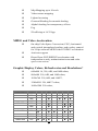
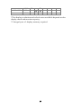
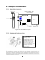
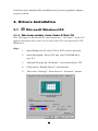
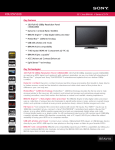
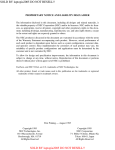
Video-67Pro-3D
Multimedia Accelerator
User’s Manual
version 2.00
COPYRIGHT ©1999 JATON CORPORATION, USA
NOTICE
The information in this document is subject to change in order to
improve reliability, design, or function without prior notice and does not
represent a commitment on the part of the company. In no event will the
company be liable for direct, indirect, special, incidental, or
consequential damages arising out of the use or the inability to use the
product or documentation, even if advised of the possibility of such
damages. No part of this manual may be reproduced or transmitted in
any form or by any means without the prior written permission of the
company.
May 1999, Rev A
2
Table of Contents
1. INTRODUCTION..........................................................................................5
1.1 COMPATIBILITY .........................................................................................5
1.2 CHECK LIST ..................................................................................................5
1.3 FEATURES.....................................................................................................6
1.3.1 Resolution and Color Selection ..................................................... 9
1.3.2 3D and 2D GUI Accelerator............................................................ 9
1.3.3 VESA DPMS and VESA DDC2B supported................................10
1.3.4 DirectDraw Supported...................................................................10
1.3.5 Geometry Processor........................................................................10
2. ADAPTER INSTALLATION
......................................................................11
2.1.1 Adapters Layouts.............................................................................11
2.1.2 Hardware Installation....................................................................11
3. DRIVERS INSTALLATION.......................................................................13
3.1 M ICROSOFT W INDOWS®95.....................................................................13
3.1.1 Welcome screen from Video-67Pro’ CD.....................................13
3.1.2 Microsoft Windows®98 .................................................................14
3.1.3 Microsoft Windows NT™4.0 .........................................................14
4. FREQUENTLY ASKED QUESTIONS (FAQ)..........................................15
5. TROUBLESHOOTING...............................................................................17
6. APPENDIX A: VIDEO MODE TABLE
......................................................19
7. APPENDIX B: PINOUT AND SYNC FREQUENCIES
............................23
7.1 A NALOG COLOR DISPLAY PINOUTS (DB 15)........................................23
7.2 CONVERSION TABLE: PIN A DAPTERS...................................................23
7.3 A NALOG VIDEO SIGNALS.........................................................................24
8. SHIELDED CABLE WARNING
.................................................................24
8.1 TRADEMARK ACKNOWLEDGMENTS..............................................25
8.2 TECHNICAL SUPPORT ..............................................................................26
9. LIMITED WARRANTY...............................................................................26
9.1 OTHER LIMITS...........................................................................................26
9.2 EXCLUSIVE OBLIGATION. ........................................................................27
9.3 OTHER STATEMENTS. .............................................................................27
3
9.4 TERMS AND CONDITIONS. .......................................................................27
9.5 SERVICES AGREEMENT :............................................................................28
9.6 ENTIRE OBLIGATION................................................................................28
10. REDUCING WARRANTY CLAIM REJECTIONS.
................................28
4
1. Introduction
Congratulation on your purchase of the Jaton 2D and 3D Graphics &
Video Accelerator Video-67Pro.
The Video-67Pro uses advanced 3DImàge975x 3D/2D Graphical User
Interface (GUI) accelerator with built-in high-speed 24-bit True Color
DAC and video acceleration circuitry and Synchronous Graphics RAM
and PCI Bus design. It accelerates graphics display up to 16.7 Million
True Color at 1024x768 at up to 85Hz vertical refresh rate.
Video-67Pro is Windows®9x Plug and Play compatible. It supports MS
DirectX and Active Movie. Free MPEG player software is also included
in the Video-67Pro software CD. It allows all MPEG-1 files and Video CD
and other titles to be played back at up to 30 frame-per-second without
expensive video hardware. It is bundled with most popular arcade
games and 3D graphics application.
1.1 Compatibility
þ
PCI Local Bus v 2.0 and v 2.1
þ
Interlace or non-interlace analog monitor
þ
Multi-sync or PS/2 monitors
þ
VESA DDC1 and DDC2B monitors
þ
PC97 Graphics Compliant
1.2 Check List
The package you have purchased should contain the following:
þ
Video-67Pro Multimedia Accelerator
þ
Software and Document CD
þ
Video-67Pro Quick Start Guide
If any of these items are missing or damaged, contact your dealer.
Important: Keep all packaging materials that accompany your adapter
in the event you need to return the product.
5
1.3 Features
þ
“Deep Green PC” power management: VBE/PM and
DAC power down
þ
PCI Specification V2.1 compliant I/O Bus
þ
VESA Super VGA BIOS Extension Standard, VBE
Version 2.0
þ
Integrated VESA feature connector
2D Graphics Acceleration
Optimized single cycle 2D graphics engine with a complete feature set in
all 8, 16 and True Color modes:
þ
256 Raster operation (ROPs)
þ
16 bit overlay with scaling
þ
Trapezoidal fill, solid or pattern
þ
Polygon fill, solid or pattern
þ
Line drawing and Clipping
þ
Stretch and Transparent BLT
þ
Internal hardware cursor (64x64x2 or 32x32x2)
þ
Built-in 64x32 pattern register
Direct Draw Support:
þ
Hardware Page Flipping
þ
Fast system memory to screen memory BLT
þ
Color and Chroma key support
þ
Transparent and stretch BLTs
þ
Overlay support for YUV and RGB
3D Graphics Acceleration
þ
Balanced the 3D pipeline
þ
Complete 3D primitive support
þ
Texture Mapping
þ
letized Texture
þ
Bi-linear filtering
6
þ
Mip-Mapping up to 8 levels
þ
Video texture mapping
þ
Lighted texturing
þ
Gouraud Shading for smooth shading
þ
Alpha blending for transparency effects
þ
Fog
þ
Z-buffering at 16/32 bpp
MPEG and Video Acceleration
þ
On-chip Color Space Conversion (CSC), horizontal
and vertical interpolated scaling, and overlay control
for 30 fps software MPEG/video CODEC acceleration
þ
Anti-tear support
þ
Direct Draw /DCI/ENDIVE acceleration with
independent x and y minimization/zoom and color
space conversion
Graphic Display Colors, Refresh rates and Resolutions*
þ
640x480 16, 256, 64K, and 16M colors,
þ
800x600 256, 64K, and 16M colors,
þ
1024x768 256, 64K, and 16M**,
þ
1280xl024 256, 64K** colors,
þ
1600x1200 256 colors,
Resolution
640x480
800x600
1024x768
1280x1024
Colors
16
256
64K
16M
256
64K
16M
256
64K
16M**
256
87i
l
l
l
l
96i
60
l
l
l
l
l
l
l
l
l
l
l
l
7
70
l
l
l
72
75
85
l
l
l
l
l
l
l
l
l
l
l
l
l
l
l
l
l
l
l
l
l
l
l
1600x1200
64K**
256
64K**
l
l
l
l
l
l
*The display resolution and refresh rates available depends on the
display mode and monitor capacity.
**4 mega bytes of display memory required.
8
Compatibility
þ
Pentium® or compatible system with PCI slot
þ
Interlace or non-interlace analog monitor
þ
Multi-sync or PS/2 monitors
þ
VESA DDC1 and DDC2B monitors detection
þ
PC97 Graphics Compliant
Software Driver
þ
MS Windows®95/98
þ
MS Windows NT® 4.0
Software drivers will be updated from time to time. Drivers not
on the CD may be downloaded from Web site or BBS.
1.3.1 RESOLUTION AND COLOR SELECTION
640x480
800x600
1024x768
1028x1024
1600x1200
16, 256, 64K(Hi-color), 16M(True-color),
256, 64K(Hi-color), 16M(True-color),
256, 64K(Hi-color), 16M(True-color),
256, 64(Hi-color),
256, 64(Hi-color),
1.3.2 3D AND 2D GUI ACCELERATOR
Accelerates the most frequently used 2D functions in today’s graphicsintensive environments plus complete 3D GUI acceleration:
þ
Complete 3D primitive support
þ
Texture mapping
þ
Gouraud Shading for smooth shading
þ
Alpha blending for transparency effects
þ
Fog
þ
Z-buffering at 16/32 bit-per-pixel
þ
Page flipping for double and triple buffering for
smooth animation effects
9
1.3.3 VESA DPMS AND VESA DDC2B SUPPORTED
Supports VESA Display Power management Signaling (DPMS) which
decreases energy consumption when used with a monitor that meets
the VESA standards for power management. Supports VESA DDC 2b
standards for automatically selecting the correct display setup on a
monitor that meets the VESA DDC standard.
1.3.4 DIRECTDRAW SUPPORTED
DirectDraw for Windows® 95/98 are memory manger for video memory.
Using such memory manager for video manger, a program can
manipulate video memory with ease, taking full advantage of the blitting
and color decompressing capabilities of Video-67Pro video hardware.
1.3.5 GEOMETRY PROCESSOR
The optional Geometry Processor off loads the intensive Geometry
Calculations from the CPU, thus triples the transform rate during 3D
graphics applications to 700K triangles per second.
10
2. Adapter Installation
2.1.1 ADAPTERS LAYOUTS
Adapter's Plate
Video - 67Pro - 3D
PCB - 82067K
1
14
CON1
DB 15 VGA
Trident
Display memory
3DImage975x
Figure 2-1 8267K Board Layout
2.1.2 HARDWARE INSTALLATION
!! WARNING !!
Discharge static
electricity by touching
the GROUND such as
metal part of your case
connected with good
power ground before you
handle the electronic
circuit boards.
The manufacturer assumes no liability for any damage, caused directly or
indirectly, by improper installation of any components by unauthorized service
personnel. If you do not feel comfortable performing the installation, consult with
a qualified computer technician.
11
To install the adapter into your system, follow these steps:
1. Turn OFF all power to your system, including any peripherals
(printer, external drives, modem, etc.).
2.
Disconnect the power cord and the monitor cable from the
back of the computer.
3.
Unfasten the cover mounting screws on your system and
remove the system cover. Refer to your system user manual for
instructions and to determine the location of the mounting
screws.
4.
Remove any graphics adapter that already exists on your
motherboard. Start by removing the screw that holds the
adapter retaining bracket in place (keep this screw, you will
need it later). Then, gently pull straight up on the adapter card
itself, and remove it from the motherboard.
5.
If appropriate, you can use the expansion slot left vacant by
the existing graphics adapter you just removed. Otherwise,
select an appropriate unused PCI bus expansion slot for the
new adapter. Refer to your computer system manual for the
location of the PCI bus expansion slots. Remove the retaining
screw that holds the slot cover in place. Slide the slot cover
out and put the screw aside (you will need it to secure the
adapter).
If you just removed an existing graphics adapter and are not
going to use that expansion slot, you can install the slot cover
you just removed from the unused expansion slot to cover the
open hole.
6.
Install the adapter. To install the adapter in the selected
expansion slot, carefully line up the gold-fingered edge
connector on the adapter directly above the expansion slot
connector on the motherboard. Then press the adapter into
place, completely, using only as much pressure as is safely
necessary. DO NOT USE excessive force. Use the (remaining)
screw you removed to secure the adapter retaining bracket in
place.
7.
Replace the computer cover. Secure the cover with the
mounting screws you removed in Step 3.
12
You have now completed the installation of your new graphics adapter
on your system.
3. Drivers Installation
3.1
ÿ
Microsoft Windows®95
3.1.1 WELCOME SCREEN FROM VIDEO-67PRO’ CD
This CD supports Windows®95 autorun feature. “Welcome” menu will
appear automatically on the screen after the CD is inserted to the CDROM drive.
Steps:
1.
Start Windows® 95 with VGA or SVGA drive detected.
2.
Insert the display Driver CD into your CD-ROM drive
(e.g. X:).
3.
Autorun file pops up “Welcome” screen from Jaton’ CD.
4.
Click on the “Display Driver” selection bar.
5.
Tab to the “Settings” then click on “ Advance” button.
13
6.
Click on “Change”, then “Have Disk”.
7.
Path into “X: \V-67Pro\WIN95\Video67P.INF” (X is the
letter of your CD-ROM drive), and click OK.
8.
The display device selected “Video-67Pro, 3DImàge975
PCI/AGP ( vXXXXXX), then press on OK button.
9.
Close and apply to finish PCI’s display driver installation.
10. Restart Windows to complete installation.
3.1.2
ÿ MICROSOFT WINDOWS®98
The steps are as same as Windows®95’s installation, but the path for subdirectory
\V-67Pro\Win98\ is instead.
3.1.3
ÿ MICROSOFT WINDOWS NT™4.0
Steps:
1.
SELECT the “Display” icon in control panel and then SELECT
the “Settings” page.
2.
SELECT “Display Type...” button in the “Settings” page.
3.
SELECT “Change...” button from the Adapter type section.
4.
SELECT “Have Disk...” button from the Change Display page.
5.
Microsoft Windows NT 4.0 will prompt you for the correct path
where the video drivers are located. ENTER the path “X:\V67Pro\Winnt4\” where X: is the CD ROM drive where the Video67Pro Software & Documents CD has been inserted.
6.
If the driver “ Trident Windows NT 4.0 Display Driver for
9397\975\985\9397DVD” is listed under the Display list, SELECT
the “OK” button to continue.
7.
Once the driver files are copied, RESTART Microsoft Windows
NT 4.0 for the changes to take effect.
8.
SELECT the desired color palette (the number of colors), desktop
area (resolution), and refresh frequency in the settings page of
Display Properties and then SELECT the “Test” button in the
same page to determine whether your selection works properly.
SELECT “Apply” to active the selected mode.
14
Note: The procedure of display driver installation it required setup with service
pack3 (Microsoft® Windows NT™4.0) first.
4. Frequently Asked Questions
(FAQ)
Q1 Why do we need 3D graphics capability in our PC?
Answer
3D technology is becoming increasingly important (and common)
not only in games, but also in other applications such as VRML,
which allows 3D scene descriptions in Web applications. 3D
technology is used for image editing, modeling, and an increasing
number of in home and business applications. In games, as well
as other applications, 3D acceleration not only allows better visual
qualities and more realistic scenery attributes than software alone,
but it also allows a higher frame rate, which translates into a more
interactive experience for the enduser.
Q2 What does “Rendering Engine” mean?
Answer
“Rendering Engine” generically applies to the part of the graphics
engine that draws 3D primitives, usually triangles. In most
implementations, the rendering engine is responsible for
interpolation of edges and "filling in" the triangle.
Q3 What does the set-up engine do in a graphics controller?
Answer
A set-up engine allows drivers to pass triangles in the form of raw
vertex information; whereas, most common designs force triangles
to be pre-processed for the rendering engine in terms of delta
values for edges, color, and texture.
Q4 Why does a 3D graphics chip need to have both a rendering
engine and a setup engine?
Answer
Any “3D application”, a game, VRML, or modeling package, can
15
benefit from 3D rendering. This is especially true of applications
that use texturing extensively, because texturing and texture
filtering are very intensive operations at the pixel level in terms of
CPU operations and demands for memory bandwidth. Without a
set-up engine in a graphics controller, the CPU has to calculate
the delta values for edges, color, and textures; the drivers need to
handle ten (10) times more extensive data. This results in slower
3D pipeline operations between the CPU and the graphics
controller.
Q5 If we use powerful CPUs, such as a Pentium™ 200, can a
standard 2D graphics card achieve 3D performance?
Answer
Yes and no. Software rendering can take advantage of "tricks"
learned by force of necessity through years of trial and error. With
such stratagems, the speed of software rendering for simple
scenes can approach that of low-level hardware 3D rendering. On
the other hand, as scenes become more complex (or frame sizes
become larger), there are conflicts between using the CPU for
high-level game logic, geometry, lighting, and rendering, all of
which increase their demands. No current CPU or system can
perform advanced quality-enhancements (bilinear filtering and
alpha blending) in real time. Even general case texture mapping
with RGB lighting is too much for the current CPU generation.
Q6 What does "software 3D" mean ?
Answer
Software 3D is generally used to mean using non-specific (2D)
hardware in conjunction with the CPU to render for 3D
applications. Some of these techniques allow usable 3D
applications when high-powered and/or MMX™-equipped CPU's
are employed along with special-case software optimization
techniques. As stated above, SW 3D can achieve credible results
with today's (software optimized) applications, but the rising
popularity of good 3D hardware at the consumer price level is
inexorably compelling the public to expect hardware level scene
enhancements and frame rates.
Q7 What is “SGRAM”?
Answer
Synchronous Graphics Random Access memory (SGRAM) is a
16
new and improved type of memory, custom-designed for graphics
use.
Q8 What is the advantage of SGRAM as compared to ordinary
DRAM?
Answer
SGRAM is now capable of running at much higher speeds than
Fast Page Mode or EDO DRAM. Also, SGRAM is able to execute
a small number of frequently executed operations, such as buffer
clears, specific to graphics applications, independently of the
controller.
5. Troubleshooting
The following are some recommended steps to take if the GUI
accelerator adapter will not boot or operate properly in your system:
1. Ensure that the monitor or TV brightness and contrast controls
are properly adjusted.
2.
Check to see if your monitor or TV is properly connected to the
card. Be sure your monitor's pin definitions match those of
your GUI accelerator card (See Appendix B). For TV out,
ensure that the composite signal is connected to a “Video
Input” RCA jack on the TV (or check the S-video connection).
Read the TV owner’s manual to select the proper signal jack for
the display.
3.
Turn the system on and confirm that the power supply is
operating properly; i.e., that the fan operates and the system
power light turns on.
4.
Check to see if the card is firmly seated in its PCI bus
expansion slot. It should not be making contact with any other
cards in the system.
Note: Turn the system off before adjusting the card.
Problem:
Solution A:
Windows hangs up during or after installing a driver.
Reread installation procedures to be sure you have
installed the drivers correctly.
Problem:
Windows color palette does not look right or colors
changing.
17
Solution:
Most likely a defective RAMDAC, memory chip, clock
chip, or crystal. Contact your dealer to have the problem
repaired.
Problem:
Solution A:
Can't display certain modes.
Run the SVM program (See the User's Guide for more
information on the SVM program). If the SVM program
fails, go to Solutions B, and C.
Solution B:
Check to see that there is enough memory on the GUI
accelerator to run this mode. For example, to run display
mode 79H (1024x768-64K colors, refer to the tables in
Section 2), 2 MB of display memory is required.
Solution C:
If Solutions A, or B do not resolve this problem, it may be
hardware related. Check the specifications of the
monitor.
18
6. Appendix A: Video Mode Table
The adapter’s video modes include all of the following:
Mode
#
TABLE 6-1: STANDARD VGA MODE SUPPORT
Resolution
Horz
Vert
Mem
Text
Mode
-Colors
KHz
Hz
Req
Res.
Type
0h,1h
320x200-16
31.4
70
512K
40x25
2h,3h
640x400-16
31.4
70
512K
80x25
Text
4h,5h
320x200-4
31.4
70
512K
40x25
Graph
6h
640x200-2
31.4
70
512K
80x25
Graph
7h
720x350-Mono
31.5
70
512K
80x25
Text
Dh
320x200-16
31.4
70
512K
40x25
Graph
Eh
640x200-16
31.4
70
512K
80x25
Graph
Fh
640x350-2
31.4
70
512K
80x25
Graph
10h
640x350-16
31.4
70
512K
80x25
Graph
11h
640x480-2
31.4
60
512K
80x30
Graph
12h
640x480-16
31.4
60
512K
80x30
Graph
13h
320x200-256
31.4
70
512K
40x25
Graph
19
Text
TABLE 6-2: EXTENDED VGA MODE SUPPORT
Mode
#
Resolution
-Colors
Horz
KHz
Vert
Hz
Mem
Req
Text Res.
Mode
Type
2Ch
2Dh_4
2Dh_3
2Dh_2
2Dh_1
2Eh_3
2Eh_2
2Eh_1
3Bh
3Ch_4
3Ch_3
3Ch_2
3Ch_0
3Dh_3
3Dh_2
3Dh_1
42/3h
44/5h_4
44/5h_3
44/5h_2
44/5h_1
46/7h_4
46/7h_3
46/7h_2
50h
51h
52h
53h
54h
55h
56h
57h
58h
59h
5Ah
5Bh_3
5Bh_2
5Bh_1
5Ch
5Dh_4
5Dh_3
5Dh_2
320x200-256
320x240-256
320x240-256
320x240-256
320x240-256
400x300-256
400x300-256
400x300-256
320x200-16M
320x240-16M
320x240-16M
320x240-16M
320x240-16M
400x300-16M
400x300-16M
400x300-16M
320x200-32K/64K
320x240-32K/64K
320x240-32K/64K
320x240-32K/64K
320x240-32K/64K
400x300-32K/64K
400x300-32K/64K
400x300-32K/64K
640x480-16
640x473-16
640x480-16
1056x350-16
1056x480-16
1056x473-16
1056x480-16
1188x350-16
1188x480-16
1188x473-16
1188x480-16
800x600-16
800x600-16
800x600-16
640x400-256
640x480-256
640x480-256
640x480-256
31.6
43.3
37.5
37.9
31.5
53.7
46.9
37.9
31.6
43.3
37.5
37.9
31.5
53.7
46.9
37.9
31.6
43.3
37.5
37.9
31.5
53.7
46.9
37.9
31.5
31.5
31.5
31.3
31.3
31.3
31.3
31.3
31.3
31.3
31.3
53.7
46.8
37.8
31.6
43.2
37.5
37.8
70
85
75
72
60
85
75
60
70
85
75
72
60
85
75
60
70
85
75
72
60
85
75
60
60
60
60
70
60
60
60
70
60
60
60
85
75
60
70
85
75
72
512K
512K
512K
512K
512K
512K
512K
512K
512K
512K
512K
512K
512K
512K
512K
512K
512K
512K
512K
512K
512K
512K
512K
512K
512K
512K
512K
512K
512K
512K
512K
512K
512K
512K
512K
512K
512K
512K
512K
512K
512K
512K
40x12
40x15
40x15
40x15
40x15
50x18
50x18
50x18
40x12
40x15
40x15
40x15
40x15
50x18
50x18
50x18
40x12
40x15
40x15
40x15
40x15
50x18
50x18
50x18
80x43
80x43
80x60
132x25
132x30
132x43
132x60
132x25
132x30
132x43
132x60
100x75
100x75
100x75
80x25
80x30
80x30
80x30
Graph
Graph
Graph
Graph
Graph
Graph
Graph
Graph
Graph
Graph
Graph
Graph
Graph
Graph
Graph
Graph
Graph
Graph
Graph
Graph
Graph
Graph
Graph
Graph
Text
Text
Text
Text
Text
Text
Text
Text
Text
Text
Text
Graph
Graph
Graph
Graph
Graph
Graph
Graph
20
Mode
#
Resolution
-Colors
Horz
KHz
Vert
Hz
Mem
Req
Text Res.
Mode
Type
5Dh_1
5Eh_3
5Eh_2
5Eh_1
5Fh_5
5Fh_4
5Fh_3
5Fh_2
5Fh_1
62h_5
62h_4
62h_3
62h_2
62h_1
63h_3
63h_2
63h_1
64h_4
64h_3
64h_2
64h_1
65h_2
65h_1
66h_4
66h_3
66h_2
66h_1
6Ah_11
6Bh
6Ch_4
6Ch_3
6Ch_2
6Ch_0
6Dh_3
6Dh_2
6Dh_1
66h_2
6Eh_5
6Eh_4
6Eh_3
6Eh_2
6Eh_1
72/3h
74/5h_4
640x480-256
800x600-256
800x600-256
800x600-256
1024x768-16
1024x768-16
1024x768-16
1024x768-16
1024x768-16
1024x768-256
1024x768-256
1024x768-256
1024x768-256
1024x768-256
1280x1024-16
1280x1024-16
1280x1024-16
1280x1024-256
1280x1024-256
1280x1024-256
1280x1024-256
1600x1200-16
1600x1200-16
1600x1200-256
1600x1200-256
1600x1200-256
1600x1200-256
800x600-16
640x400-16M
640x480-16M
640x480-16M
640x480-16M
640x480-16M
800x600-16M
800x600-16M
800x600-16M
1600x1200-256
1024x768-16M
1024x768-16M
1024x768-16M
1024x768-16M
1024x768-16M
640x400-32K/64K
640x480-32K/64K
31.4
53.7
46.8
37.8
68.7
60.4
56.4
48.5
35.5
68.7
60.0
56.4
48.3
35.5
80.0
63.9
46.4
91.1
80.0
63.9
46.4
75
62.5
106.3
93.8
75
62.5
37.8
31.6
43.2
37.5
37.8
31.4
53.7
46.8
37.8
75
68.7
60.0
56.4
48.3
35.5
31.6
43.2
60
85
75
60
85
75
70
60
87i
85
75
70
60
87i
75
60
87i
85
75
60
87i
60
96i
85
75
60
96i
60
70
85
75
72
60
85
75
60
60
85
75
70
60
87i
70
85
512K
512K
512K
512K
512K
512K
512K
512K
512K
1M
1M
1M
1M
1M
1M
1M
1M
2M
2M
2M
2M
1M
1M
2M
2M
2M
2M
512K
2M
2M
2M
2M
2M
2M
2M
2M
2M
4M
4M
4M
4M
4M
1M
1M
80x30
100x37
100x37
100x37
128x48
128x48
128x48
128x48
128x48
128x48
128x48
128x48
128x48
128x48
160x64
160x64
160x64
160x64
160x64
160x64
160x64
200x75
200x75
200x75
200x75
200x75
200x75
100x75
80x25
80x30
80x30
80x30
80x30
100x37
100x37
100x37
200x75
128x48
128x48
128x48
128x48
128x48
80x25
80x30
Graph
Graph
Graph
Graph
Graph
Graph
Graph
Graph
Graph
Graph
Graph
Graph
Graph
Graph
Graph
Graph
Graph
Graph
Graph
Graph
Graph
Graph
Graph
Graph
Graph
Graph
Graph
Graph
Graph
Graph
Graph
Graph
Graph
Graph
Graph
Graph
Graph
Graph
Graph
Graph
Graph
Graph
Graph
Graph
21
Mode
#
Resolution
-Colors
Horz
KHz
Vert
Hz
Mem
Req
Text Res.
Mode
Type
74/5h_3
74/5h_2
74/5h_1
76/7h _4
76/7h_3
76/7h_2
78/9h_5
78/9h_4
78/9h_3
78/9h_2
78/9h_1
7A/Bh_3
640x480-32K/64K
640x480-32K/64K
640x480-32K/64K
800x600-32K/64K
800x600-32K/64K
800x600-32K/64K
37.5
37.8
31.4
53.7
46.8
37.8
68.7
60.0
56.4
48.3
35.5
80
75
72
60
85
75
60
85
75
70
60
87i
75
1M
1M
1M
1M
1M
1M
2M
2M
2M
2M
2M
4M
80x30
80x30
80x30
100x37
100x37
100x37
128x48
128x48
128x48
128x48
128x48
160x64
Graph
Graph
Graph
Graph
Graph
Graph
Graph
Graph
Graph
Graph
Graph
Graph
63.9
60
4M
160x64
Graph
46.4
87i
4M
160x64
Graph
106.3
85
4M
160x64
Graph
93.8
75
4M
160x64
Graph
75.0
60
4M
160x64
Graph
62.5
96i
4M
160x64
Graph
7A/Bh_2
7A/Bh_1
7C/Dh_4
7C/Dh_3
7C/Dh_2
7C/Dh_1
1024x768-32K/64K
1024x768-32K/64K
1024x768-32K/64K
1024x768-32K/64K
1024x768-32K/64K
1280x102432K/64K
1280x102432K/64K
1280x102432K/64K
1600x120032K/64K
1600x120032K/64K
1600x120032K/64K
1600x120032K/64K
NOTES :
1. VESA mode. Same as 5Bh_1.
2. The "i" in the vertical frequency column denotes "interlaced". The "N"
and "P" in the TV Out column denote "NTSC" and "", respectively.
22
7. Appendix B: Pinout and Sync
Frequencies
7.1 Analog Color Display Pinouts (DB 15)
PIN
FUNCTION
1
Red Video1
2
Green Video1
3
Blue Video1
4
Not Used
5
Ground
6
Red Return (ground)
7
Green Return (ground)
8
Blue Return (ground)
9
Vcc (+5v DDC Power)
10
Sync Return (ground)
11
Monitor ID (not used)
12
SDA (DDC support)
13
Horizontal Sync
14
Vertical Sync
15
SCL (DDC support)
Note: Analog monochrome type monitors use green video for all
video input and ignore red and blue video.
7.2 Conversion Table: Pin Adapters
If you will be using a 9-to-15 pin adapter cable to link your 9 pin monitor
connector to the 15 pin accelerator card connector, check Table 7-2
carefully before you install the cable. The 9-to-15 pin adapter cables are
available from a variety of sources, but they need to match the
specifications in Table 7-2 to work properly with your new card.
23
The adapter cable requires a D-shaped 9 pin female connector and a Dshaped 15 pin male connector.
TABLE 7-2. 9-TO-15 PIN CONVERSION TABLE
9 PIN SIGNALS
PIN NO.
15 PIN SIGNALS
PIN NO.
Red
1
Red
1
Green
2
Green
2
Blue
3
Blue
3
Horz Sync
4
Horz Sync
13
Vert Sync
5
Vert Sync
14
Red Ground
6
Return Red
6
Green Ground
7
Return Green
7
Blue Ground
8
Return Blue
8
Sync Ground
9
Digital Ground
10
Ground
5
7.3 Analog Video Signals
Black Level = 0 V
Full Intensity (White) Level = +0.7 V
8. SHIELDED CABLE WARNING
This equipment has been tested and found to comply with the limits for
a Class B digital device, pursuant to Part 15 of the FCC Rules. These
limits are designed to provide reasonable protection against harmful
interference in a residential installation. This equipment generates, uses
and can radiate radio frequency energy and, if not installed and used in
accordance with the instructions, may cause harmful interference to
radio communications. However, there is no guarantee that interference
will not occur in a particular installation. If this equipment does cause
interference to radio or television reception, which can be determined by
turning the equipment off and on, the user is encouraged to try to
correct the interference by one or more of the following measures:
Reorient or re-locate the receiving antenna.
Increase the separation between the equipment and the receiver.
24
Connect the equipment into an outlet on a circuit different from that
to which the receiver is connected.
Consult an experienced radio/TV technician for help.
The user may find the following booklet prepared by the Federal
Communications Commission helpful:
“How to Identify and Resolve Radio/TV Interference Problems”.
This booklet is available from the U.S. Government Printing Office,
Washington, DC 20402, Stock No. 004-000-00345-4.
This device complies with Part 15 of the FCC Rules. Operation is subject
to the following conditions: (1) this device may not cause harmful
interference, and (2) this device must accept any interference received,
including interference that may cause undesired operation,
“SHIELD INTERFERENCE CABLE(S) MUST BE USED ACCORDING
TO FCC 15.27©.”
CAUTION: Changes or modifications not expressly approved by the
Manufacturer could void your authority to operate this equipment in
accordance with FCC rules and regulations.
8.1 TRADEMARK ACKNOWLEDGMENTS
Trident Microsystems, Inc. 1997. All rights reserved.
Trident Microsystems, Inc. 3DImàge975x™ User’s Guide
Trident Microsystems, Inc. assumes no responsibility for the use of any circuit other than circuits
embodied in an Trident Microsystems, Inc. product. No other circuit patent licenses are implied.
IBM is a registered trademark and PS/2 and OS/2 are trademarks of International Business Machines
Corp.
Microsoft, Microsoft Windows, and Microsoft Word are registered trademarks of Microsoft Corp.
Pentium is a trademark of Intel Corp.
RAMDAC is a trademark of Brooktree Corporation.
3DImàge9750, 3DImàge9753 and TVGA are registered trademarks of Trident Microsystems, Inc.
VESA is a trademark of Video Electronics Standards Association.
All other product names or trademarks are property of their respective owners.
Copyright protection claimed includes all forms and matters of copyrightable material and
information now allowed by statutory or judicial law or hereinaffer granted, including without
limitation, material generated from the software programs which are displayed on the screen such as
icons, screen display looks, etc. Reproduction or disassembly of embedded computer programs or
algorithms prohibited.
25
8.2 Technical Support
In the event you have a technical problem with this product,
please read the README files in the driver disks. Updated
drivers are available through Jaton BBS and Web site. Have
following information handy when you contact technical
support:
þ Name of the product.
þ
Software Driver and Version.
þ
System Information, such as CPU speed, BIOS version, Monitor
Specification, etc.
þ
Description of the problems including any error messages.
Telephone:
(408)934-9369 9-5 PST Mon. - Fri.
BBS modem dial-up:
(408)263-8529 (8N1)
FAX :
(408)942-6699
Internet:
http://www.jaton.com
email :
[email protected]
9. Limited Warranty.
Manufacturer warrants that the products sold hereunder are free from
defects in material and workmanship for a period of two (2) years from
manufacturing date. This limited warranty applies only to the original
purchaser of Jaton Product and is not transferable. This limited warranty
does not apply if failure to the Product Registration, or over thirty (30)
days from purchase (original invoice date). This Limited Warranty does
not cover any incompatibilities due to the user’s computer, hardware,
software or any related system configuration in which the Jaton
Products interfaces. Proof of purchase will be require before any
consideration by Manufacturer occurs.
9.1 Other Limits.
The forgoing is in lieu of all other warranties, expressed or implied.
Including but not limited to the implied warranties of merchantability
26
and fitness for a particular purpose. Manufacturer does not warrant
against damages or defects arising out of improper or abnormal use of
handling of the products; against defects or damages arising from
improper installation (where installation is by persons other than
Manufacturer), against defects in products or components not
manufactured or installed by Manufacturer, or against damages result
from non-manufacturer made products or components. This warranty
does not apply if the Product has been damaged by accident, abuse, nor
misuse. This warranty also does not apply to products upon which
repairs have been effected or attempted by persons other than pursuant
to written authorization by Manufacturer.
9.2 Exclusive Obligation.
This warranty is exclusive. The sole and exclusive obligation of
Manufacturer shall repair or replace the defective products in the
manner and for the period provided above. Manufacturer shall not have
any other obligation with respect to the Products or any part thereof,
whether based on contract, tort, strict liability or otherwise. Under no
circumstances, whether based on this Limited Warranty or otherwise,
Manufacturer shall not be liable for incidental, special, or consequential
damage.
9.3 Other Statements.
Manufacturer’s employees or representatives’ ORAL OR OTHER
WRITTEN STATEMENTS DO NOT CONSTITUE WARRANTIES ,
shall not be relied upon by Buyer, and are not a part of the contract for
sale or this Limited Warranty.
9.4 Terms and Conditions.
Direct Jaton Customer:
This warranty applies only for a period of
two (2) years from purchase date of Jaton
original invoice.
Reseller/ Vendor:
This warranty applies only for a period of
two (2) years from manufacturing date.
Registered User:
This warranty applies only for a period of
two (2) years from purchase date and
register within 30 days of purchase date
from legal reseller.
Others:
If the products do not conform to this
Limited Warranty (as herein above
described), Manufacturer should charge
services such as repair, replacement
27
whether based on its costs. Shipping and
installation of the replacement Products
or replacement parts shall be at User’s
expanse.
9.5 Services agreement:
(1) All applicants shall completed service request form from
Manufacturer.
(2) All returned checks will be charged a $20.00 fee by
Manufacturer.
(3) All repair and replacement services allow 4-6 weeks from the
date of receiving by Manufacturer.
(4) All products without warranties require service processing fee
$20 (payment in advance), which is not refundable.
9.6 Entire Obligation.
This Limited Warranty states the entire obligation of Manufacturer with
respect to the Products. If any part of this Limited Warranty is
determined to be void or illegal, the remainder shall remain in force and
effect. Some states do not allow limitation of implied warranties, or
exclusive or limitation on product incidental or consequential damages,
so above limitation may not apply to you. This warranty gives you
specific legal rights. You may have other rights which may vary from
state to state.
This warranty applies only to this product, and is governed by the law
of the State of California.
10. Reducing Warranty Claim
Rejections.
To reduce the potential of incurring damages not covered by
Manufacturers warranties, we strongly recommend the following:
•
read your manuals before installing peripherals and/or
before making changes to the machine’s configuration;
28
•
•
•
ask your dealer if there are any known problems with the
system requirements or installation procedures for any
add-on products that your are purchasing;
buy industry standard products where compatibility issue
are more likely to surface;
If you are unsure about installation for a new product,
contact your dealer’s service department.
We believe it is important for you to know and understand what your
warranty coverage provides and what it does not.
We also want you to be aware that most hardware warranties only relate
to the function of the hardware. In most cases, no assurances are given
by the manufacturer that the hardware item will work in conjunction with
any other hardware item. If a computer product is not working because
it is not compatible with another product, or because it has not been
properly installed and set-up, the manufacturer does not pay for the
service time. To help avoid these inconveniences, contact a
professional consultant that one can help you determine the possibility
of incompatibility issue before you purchase add-on or accessories.
29