1
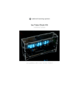
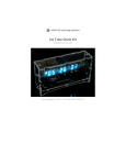
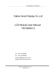
Monochron
Created by lady ada
Last updated on 2014-08-06 04:30:24 PM EDT
Guide Contents
Guide Contents
2
Overview
6
Mono-chromatic clock
6
Overview
6
Videos!
7
FAQ
8
Frequently Asked Questions
8
My clock is acting odd. It works then it freaks out
8
How long will the battery run the clock for?
8
What is the current draw of the clock? How much energy does this clock require to run?
How can I reprogram the kit?
88
What kind of display does it use?
8
Can I use a different display?
8
Design
9
Design documetns
9
Overview
9
Power supply
9
Real Time Clock
9
Switches
10
Display
11
Microcontroller
13
Firmware
13
Make it!
15
Make it!
15
Make your kit!
15
Preparation
16
Prepare to qualify!
16
Prep
16
Tools
16
Parts list
21
© Adafruit
Industries
https://learn.adafruit.com/monochron
Page 2 of 137
Parts list
21
Parts list
21
Bill of Materials
21
Solder it!
25
Assembly instructions
25
Case it!
58
Enclosure assembly
58
Case it!
58
Prep
58
Sides and front
59
Bottom
67
Top
70
Back
73
Use it!
77
User manual
77
Time display
77
Date display
77
Power
78
Buttons
78
Alarm
79
Contrast adjust
80
Configuring the clock
81
Alarm
82
Alarm set
82
Turning the Alarm on/off
82
Alarm & snoozing
82
Setting the alarm time
82
Time
86
Setting the time
86
Set time
86
Date
88
Setting the date
88
Save the date!
88
© Adafruit
Industries
https://learn.adafruit.com/monochron
Page 3 of 137
Region
91
Set region
91
Regioning
91
Backlight
95
Set backlight brightness
95
Adjust!
95
Mods
97
Modificating your kit for fun!
97
What are the mods?
97
Power cable
98
Neater power cord
98
The mod!
98
Lets go!
98
Clocks!
112
Other firmwares
112
EmuChron
112
MultiChron
112
RATTChron
113
XDaliChron
113
SevenChron
113
IntruderChron
114
Updating
116
Updating your clock!
116
AVR Programmer or FTDI cable?
116
Installing programming software
116
Installing the FTDI driver
117
FTDI name and Set RTS on Close
124
Test!
128
Uploading your favorite clock
133
Download
135
Download
135
Firmware & PCB
© Adafruit
Industries
135
https://learn.adafruit.com/monochron
Page 4 of 137
Other firmwares!
135
Forums
136
Buy Kit
137
© Adafruit
Industries
https://learn.adafruit.com/monochron
Page 5 of 137
Overview
Mono-chromatic clock
Overview
The second clock kit from ladyada & Adafruit Industries, we present MONOCHRON!
We wanted to make a clock that was ultra-hackable, from adding a separate battery-backed
RTC to designing the enclosure so you could program the clock once its assembled.
128x64 (http://adafru.it/cxx) LCD (KS0108) - we special-ordered the black and white
display
ATmega328 processor (we even stuck an 'arduino' stk500 bootloader on there too)
Laser cut enclosure in black acrylic (http://adafru.it/c4o)
Beeping/blinking alarm with 10 minute snooze (http://adafru.it/c4p)
Battery backed-up real time clock (DS1307 (http://adafru.it/con)) keeps time even
when power is lost for years
European/US 12 or 24 hour time display as well as date (http://adafru.it/c4q)
Completely open source hardware, all firmware, layout and CAD files are yours to
mess with (http://adafru.it/c4r)
Plenty of space for mods, a prototyping area for soldering stuff in
© Adafruit
Industries
https://learn.adafruit.com/monochron
Page 6 of 137
Videos!
Amanda 'w0z' Wozniak (http://adafru.it/c4s) - designed the beautiful enclosure
Caitsith2 (http://adafru.it/dNU) - beta-tested, and submitted some great firmware
mods
Buro Vormkijgers (http://adafru.it/c4u) - inspired people to relive the joy of their retroyouth (we are in no way associated with Buro Vormkijgers, at the request of Sander
Mulder on 4/10/2010 we've included a link to his site here (http://adafru.it/c4v))
MONOCHRON® is a registered trademark of Adafruit Industries
© Adafruit
Industries
https://learn.adafruit.com/monochron
Page 7 of 137
FAQ
Frequently Asked Questions
My clock is acting odd. It works then it freaks out
Make sure you install the CR1220 coin cell battery, the RTC chip needs it even if you don't
use the battery backup.
How long will the battery run the clock for?
As long as the clock is plugged in, the backup battery isn't used. When unplugged, the clock
should keep time for many years - 20mAh / 500nA = 4.5 years
What is the current draw of the clock?
How much energy does this clock require to run?
We use a high-efficiency white LED backlight display so the whole clock only uses about
50mA at 5V! Likewise, the power supply we provide is a nice switching supply, which means
it runs at 80% efficiency or higher! So total power usage for the clock is under a half Watt.
How can I reprogram the kit?
Check out this detailed tutorial (http://adafru.it/c4w)
What kind of display does it use?
The MONOCHRON is designed to use a KS0108 LCD, these are monochrome displays that
are very very well documented and understood. They're very popular for hobbyist use.
Can I use a different display?
The clock is designed to control a monochrom KS0108 display. Note that these displays
come in two 'flavors' of pinouts, you'll want one that is equivalent to our stock KS0108
LCD (http://adafru.it/188). So you can plug in any KS0108 display with the same pinout and it
will Just Work.
It's possible to use a different kind of display like a SED1330 but note that it won't just work,
you'll need to write some code and possibly rewire it!
MONOCHRON® is a registered trademark of Adafruit Industries
© Adafruit
Industries
https://learn.adafruit.com/monochron
Page 8 of 137
Design
Design documetns
Overview
Here is a rough overview of how the kit is designed to work.
Click here for the full schematic (http://adafru.it/cxy) (http://adafru.it/cxy)
Power supply
The power supply is very simple. We have a DC power jack, positive tip J1 which feeds into
our polarity protection diode D1. After that is two capacitors C1 and C2 to smooth out the
input voltage. Next are the 7805 (http://adafru.it/1794)'s. We wanted to have the option of
TO-220 (1 amp or more, if you have an EL backlit display or wanted to run something hefty)
or TO-92 (100mA). The kit comes with TO-92 as it only requires ~50mA of current, well
within the limits of the smaller package. C3 and C4 are stabilization and smoothing caps for
the output of the regulator.
Real Time Clock
© Adafruit
Industries
https://learn.adafruit.com/monochron
Page 9 of 137
Next we'll discuss the RTC (real time clock) chip. We are using the
DS1307 (http://adafru.it/cwB) which is a 8-DIP clock with battery backup. Normally the clock
runs off of the 5v supply. If the supply dies (say because of power loss) the chip switches to
the CR1220 battery, which can run it for many years. The RTC requires a 32.768KHz 12.5pF
crystal Q1 to keep time. To communicate with the main chip, i2c is used. I2c is a 2-wire
protocol that uses open-drain transistors to communicate, thus we have R8 and R9 which
are the two pull-up resistors for the open-drain inputs. SQW is a square wvae output that we
do not use.
Note that the RTC will act erratically if the battery is not placed. If you are absolutely sure you
don't want battery backup, stick some tinfoil in the battery holder. Otherwise i2c will hang
and it will be a real pain to figure out whats going on!
Switches
© Adafruit
Industries
https://learn.adafruit.com/monochron
Page 10 of 137
There are 2 sets of switches, the configuration tactile buttons and the alarm switch. The
alarm switch is simply to indicate whether the alarm is on or off. To save a pin, the indicator
LED (LED1) is connected directly to the switch paddle through a current limiting resistor R7.
Since we don't have a lot of spare pins on the microcontroller, we save 2 by having the
pushbuttons connected 'totem-pole' style to the analog-digital converter. as each button is
pressed, the resistor divider made of R3-R6 changes and thus we can tell which switch has
been pushed. Note that we can't tell if more than one button is pressed - in this application
we dont need to so thats OK.
Display
© Adafruit
Industries
https://learn.adafruit.com/monochron
Page 11 of 137
The main display is a monochrome KS0108 based LCD with 128x64 pixels (two 64x64 pixel
controllers) It is a well known and documented display. They are common in electronics
shops, and run at 5V. The unfortunate thing about them is they're quite sluggish and so they
need software optimization for any sort of animation.
This display has a parallel 8-bit interface and so it needs 8 bits for the port (DB0-7), and
then 2 chip-select lines (CS0 and CS1) as well as an enable pin E, read/write select pin RW
and command/data pin RS.
V0 is the contrast pin, and must be connected to a 10K pot tied between ground and VEE
which is a negative voltage generated by the LCD.
The backlight of the display is an LED (anode is A cathode is K and is connected to ground).
We use a 100 ohm (5V - 3.4Vf / 20mA = 80 ohms or so) resistor R2 to se the brightness. If
the resistor is placed in slot R2 we save a pin but cannot adjust the brightness. if R2' is
used, the backlight is connected to a PWM output of the micro which allows us to control the
brightness in the configuration.
© Adafruit
Industries
https://learn.adafruit.com/monochron
Page 12 of 137
Microcontroller
Finally we get to the microcontroller. The microcontroller does not have a crystal, we'll be
running it using the internal 8MHz oscillator which is good enough, this frees up two pins. R1
is used because otherwise the LCD output on that pin conflicts with programming (MISO
and SCK go into an input pin on the LCD).
Because of the massive # of pins, the display requires, the only free pins are RX, TX, and
PC1. PD3 is free if you solder R2 into the hardwired slot (see above). If you'd like to
connect something to the i2c bus, there are already pull ups on there.. If you really need an
extra pin, LCD_CS1 is always the invertion of LCD_CS0 so you can use a transistor and a
pullup to create a 'not gate' and the use either PC0 or PD2.
Firmware
The firmware uses Pascal Stang's great AVR libraries. The i2c.c and i2c.h files (which are
© Adafruit
Industries
https://learn.adafruit.com/monochron
Page 13 of 137
used to access the RTC) and ks0108 files are from that project. There were a few bugs and
sluggish things about the KS0108 library so we made a few modifications to allow inverted
drawing, fast rectangle (blitting instead of setting one pixel at a time), etc. The KS0108
library can draw basic shapes and best of all, has a 5x7 font so you can easily print text on
the screen.
The clock core code is in ratt.c, that's where the stuff that deals with setting and updating
the time, snooze, talking to the RTC, beeping the piezo and running the main loop that
animates the display.
Button debouncing and interface code is in buttons.c. The ADC runs constantly to look for
changes in the resistor divider.
The configure menu system is all in config.c - it's basically a state machine, you shouldn't
have to modify anything there.
The real drawing and any display logic code happens in anim.c. step() is called every TICK
milliseconds, and the microcontroller does the work of figuring out where the 'ball' is heading
and then whether each 'stick' should attempt to hit it or miss it (depending on whether the
time changed).
If you want to design a clock display, you would pretty much just want to edit anim.c and
have the init() and step() code change.
MONOCHRON® is a registered trademark of Adafruit Industries
© Adafruit
Industries
https://learn.adafruit.com/monochron
Page 14 of 137
Make it!
Make it!
Make your kit!
This is a very easy kit to make, just go through each of these steps to build the kit:
1.
2.
3.
4.
Tools and preparation (http://adafru.it/c4A)
Check the parts list (http://adafru.it/c4B)
Solder it (http://adafru.it/c4C)
Case it (http://adafru.it/c4o)
MONOCHRON® is a registered trademark of Adafruit Industries
© Adafruit
Industries
https://learn.adafruit.com/monochron
Page 15 of 137
Preparation
Prepare to qualify!
Prep
Learn how to solder with tons of tutorials! (http://adafru.it/aTk)
Don't forget to learn how to use your multimeter too! (http://adafru.it/aZZ)
Tools
There are a few tools that are required for assembly. None of these tools are included. If
you don't have them, now would be a good time to borrow or purchase them. They are very
very handy whenever assembling/fixing/modifying electronic devices! I provide links to buy
them, but of course, you should get them whereever is most convenient/inexpensive. Many
of these parts are available in a place like Radio Shack or other (higher quality) DIY
electronics stores.
So ldering iro n
Any entry level 'all-in-one' soldering iron that
you might find at your local hardware store
should work. As with most things in life, you get
what you pay for.
Upgrading to a higher end soldering iron setup,
like the Hakko FX-888 that we stock in our
store (http://adafru.it/dyY), will make soldering
fun and easy.
Do not use a "ColdHeat" soldering iron! They
are not suitable for delicate electronics work
and can damage the kit (see
here (http://adafru.it/aOo)).
Click here to buy our entry level adjustable
30W 110V soldering iron (http://adafru.it/180).
Click here to upgrade to a Genuine Hakko FX888 adjustable temperature soldering
iron. (http://adafru.it/dyY)
© Adafruit
Industries
https://learn.adafruit.com/monochron
Page 16 of 137
So lder
You will want rosin core, 60/40 solder. Good
solder is a good thing. Bad solder leads to
bridging and cold solder joints which can be
tough to find.
Click here to buy a spool of leaded solder
(recommended for
beginners) (http://adafru.it/145).
Click here to buy a spool of lead-free
solder (http://adafru.it/734).
© Adafruit
Industries
https://learn.adafruit.com/monochron
Page 17 of 137
Multimeter
You will need a good quality basic multimeter
that can measure voltage and continuity.
Click here to buy a basic
multimeter. (http://adafru.it/71)
Click here to buy a top of the line
multimeter. (http://adafru.it/308)
Click here to buy a pocket
multimeter. (http://adafru.it/850)
© Adafruit
Industries
https://learn.adafruit.com/monochron
Page 18 of 137
Flush Diago nal Cutters
You will need flush diagonal cutters to trim the
wires and leads off of components once you
have soldered them in place.
Click here to buy our favorite
cutters (http://adafru.it/152).
So lder Sucker
Strangely enough, that's the technical term for
this desoldering vacuum tool. Useful in cleaning
up mistakes, every electrical engineer has one
of these on their desk.
Click here to buy a one (http://adafru.it/148).
Helping Third Hand With Magnifier
Not absolutely necessary but will make things
go much much faster, and it will make soldering
much easier.
Pick one up here (http://adafru.it/291).
© Adafruit
Industries
https://learn.adafruit.com/monochron
Page 19 of 137
MONOCHRON® is a registered trademark of Adafruit Industries
© Adafruit
Industries
https://learn.adafruit.com/monochron
Page 20 of 137
Parts list
Parts list
Bill of Materials
Check to make sure your kit comes with the following parts. Sometimes we make mistakes
so double check everything and email [email protected] if you need replacements!
Image
Part # &
Info rmatio n
Name
Descriptio n
IC1
Microcontroller
(preprogrammed with
ATmega328P-20PU 1
firmware when
purchased in a kit)
IC2
7805 (TO-220
package) or 78L05
(TO-92)
Qty
78L05
1
1
5V regulator
© Adafruit
Industries
IC3
Real time clock
DS1307
Q1
32.768 KHz, 12.5 pF
watch crystal
Generic 32.768KHz
1
crystal
LED1
Green or red 3mm
LED
3mm indicator LED
1
D1
Power diode
1N4001
1
https://learn.adafruit.com/monochron
Page 21 of 137
Electrolytic capacitor
C2
47uF / 25V
(or higher)
Generic
1
C4
100uF / 6.3V
capacitor
(or higher)
Generic
1
C1, C3, C5
Bypass capacitor
(0.1uF)
Generic
3
Generic
1
Generic
6
Generic
2
100 ohm resistor
R2'
Brown Black Brown
Gold
R1, R3, R4,
R5, R6, R7
1/4W 5% 1.0K resistor
Brown Black Red Gold
1/4W 5% 2.2K resistor
R8, R9
© Adafruit
Industries
Red Red Red Gold
TM1
10K trim
potentiometer 6mm
side adjust
J1
2.1mm Power Jack
CUI PJ-202AH
1
IC1'
28-pin socket
28 pin socket
1
https://learn.adafruit.com/monochron
1
Page 22 of 137
IC1'
8-pin socket
8 pin socket
1
2x3 pin header
1
Generic
1
DO NOT SOLDER
THIS INTO THE
FTDI PORT
0.1" male header
strip
1
Right angle SPDT
switch
C&K
1
OS102011MA1QN1
6 pin header,
0.1"x0.1" spacing
ICSP
DO NOT SOLDER
THIS IN
LCD
20 pin female header
Straight male header
LCD & FTDI
SW1
S1, S2, S3
Right angle tactile
switch
EVQ-PF008K
3
8.35mm long actuator
© Adafruit
Industries
SPK
Piezo Speaker
PS1240P02AT
1
BATT
12mm 3V lithium coin
cell
CR1220
1
https://learn.adafruit.com/monochron
Page 23 of 137
BATT'
12mm coin cell holder Keystone 3001
1
LCD
KS0108 LCD
Black with white
backlight preferred &
is included in the kit
1
PCB
Circuit board
1
STANDOFF
1/2" 4-40 round F-F
threaded aluminum
standoff
4
SPACER
3/8" plastic spacer
4
SCREW
5/8" 4-40 stainless
steel machine screw
8
ENCLOSURE
6-piece laser cut
enclosure
MONOCHRON® is a registered trademark of Adafruit Industries
© Adafruit
Industries
https://learn.adafruit.com/monochron
Page 24 of 137
Solder it!
Assembly instructions
Here are the step by step instructions...just want to remind you not to solder in the 6-pin
FTDI header or ISP header!
Get ready by checking all your parts against the
Bill of Materials (parts list) (http://adafru.it/c4B).
Once you are sure you have everything,
prepare your workspace by heating up the
soldering iron, wetting the sponge and
arranging your tools and parts so they will be
convenient.
© Adafruit
Industries
https://learn.adafruit.com/monochron
Page 25 of 137
OK! Lets start! First thing we will solder in is the
resistor R1, which has a 1Kohm value. You can
tell which one this is because it has Brown Black
Red Gold stripes on it. Bend this resistor into a
staple as shown. Then slip it into the spot in the
lower middle, right over the matching
silkscreen that is labeled R1. Resistors are not
'polarized' so you can place them either way
and they work the same. The resistor should sit
right up against the PCB.
This resistor is used to allow the
microcontroller to be programed with an InSystem Programmer while the LCD is
connected (they share a pin).
© Adafruit
Industries
https://learn.adafruit.com/monochron
Page 26 of 137
Bend the leads out of the staple so it holds the
part in place and flip over the PCB.
Using your soldering iron tip, press and heat
both the pad (the silver ring around the hole)
and lead (wire) at the same time for 2 or 3
seconds. Then poke the end of the solder in to
create a nice solder joint. Do this for both
leads.
© Adafruit
Industries
https://learn.adafruit.com/monochron
Page 27 of 137
Using your diagonal cutters, cut off the long
leads just above the solder joint.
You should have nice shiny solder points that
are rounded and fill the entire pad.
© Adafruit
Industries
https://learn.adafruit.com/monochron
Page 28 of 137
Now we will continue by placing the remaining 5
1K resistors.
Place R3, R4, R5, and R6. These resistors
make up a multiplexed button-reading circuit
that allows the chip to listen to 3 buttons using
only one analog pin.
Place R7 this is the current limiting resistor for
LED1 (the alarm indicator).
© Adafruit
Industries
https://learn.adafruit.com/monochron
Page 29 of 137
Flip over and solder the resistors just like
before, making sure to heat each joint and fill it
with solder completely.
© Adafruit
Industries
https://learn.adafruit.com/monochron
Page 30 of 137
Then clip all of the leads.
© Adafruit
Industries
https://learn.adafruit.com/monochron
Page 31 of 137
Next we will solder in last 3 resistors.
R8 and R9 are 2.2K (red red red gold) resistors
that are used as i2c pull-ups for the real time
clock (the datalines require pull-up resistors).
R2' is a 100 ohm resistor (brown black brown
gold) that sets the brightness for the LCD.
Please no te: This resistor can be soldered
into R2 (fixed brightness) or R2' (software
controllable). In these photos we soldered
them into R2 but we suggest you use
R2'which will allow you to control the
brightness easily (it turned out the LCD
backlights vary quite a bit from one to the
other). So please igno re the inco rrect
resisto r lo catio n here and the use R2'
slo t!
© Adafruit
Industries
https://learn.adafruit.com/monochron
Page 32 of 137
Flip over the PCB and solder in the resistors.
(Don't forget to use R2' not R2!)
Then clip them short
© Adafruit
Industries
https://learn.adafruit.com/monochron
Page 33 of 137
Now that we are done with the resistors it's
time to solder in the ceramic capacitors.
Capacitors are used to smooth out power
supply ripples and also to block DC voltages.
C1 is the input (9V) filter capacitor, C3 is the
output (5V) filter capacitor. C5 is used to
program the chip using an FTDI chip, it blocks
the DC 'reset' pin and turns it into a pulse.
Ceramic capacitors, like resistors, are not
polarized so they can go in 'either way'
Flip over the board and solder in the 3 ceramic
capacitors.
Then clip the leads (not shown).
© Adafruit
Industries
https://learn.adafruit.com/monochron
Page 34 of 137
Now we are ready to build the power supply.
The power supply is what takes 9V from the
outside world (from power plug) and regulates
it down to 5V that is safe for the microcontroller
to run at.
The first part is the 2.1mm DC jack. This is the
mechanical connection. It fits in the lower left
hand side of the PCB and you can snap it into
place (may need a bit of a squeeze) - make
sure it sits flat against the circuit board!
© Adafruit
Industries
https://learn.adafruit.com/monochron
Page 35 of 137
If it doesn't snap in place, you can keep it from
falling out by 'tack' soldering it a little from the
top on one of the pins.
Now flip over the PCB and solder the three big
pins. Make sure to heat up the pads and pins
for a few seconds before shoving tons of
solder in there. This is a mechanical solder
connection so you really want to get the big
round pads filled up.
© Adafruit
Industries
https://learn.adafruit.com/monochron
Page 36 of 137
Next is D1 the 1N4001 protection diode.
Diodes are semiconductors, in particular a
diode will only pass current in one direction.
This protects the power supply and micro from
if someone plugs in a power supply that is AC
or negative polarity. Instead of going poof, the
diode will block the negative voltage.
Because diodes only conduct in one direction,
it's important to put it in right. Look for a white
stripe at one end, this is the catho de, now
look on the PCB, there is a silkscreened diode
and one side also has a white stripe, make sure
to match those up!
After the diode is the 7805 voltage regulator
IC2. The 7805 regulators up to 17VDC down to
a nice steady 5V. Because we are using a good
quality LCD with an LED backlight, we don't
need a big honking power supply chip. The TO92 package 7805 can supply about 100mA.
However, if you end up doing mods or want to
use an LCD with an EL backlight, you may end
up using IC2' which is the TO-220 package
version and can provide 1.0 Amp of current!
OK, so the regulator has a flat side and a round
side, the three pins go in the pads, and the
outline on the silkscreen should match the
shape of the regulator.
© Adafruit
Industries
https://learn.adafruit.com/monochron
Page 37 of 137
Now flip over the PCB and solder in the diode
and regulator.
Clip the leads (not shown).
© Adafruit
Industries
https://learn.adafruit.com/monochron
Page 38 of 137
Now we are ready to do our first test. Clear off
your table and make sure there are no wires or
bits that could short out the PCB.
Place the PCB down and insert the power
supply plug into the jack all the way. The jack
should not move at all, if you soldered it
enough. Now using your multimeter in voltage
mode, measure between the two points shown
(you can zoom by clicking on the picture).
You should get 4.9 to 5.1VDC
If you do n't then stop, check your work. Make
sure your multimeter has a fresh battery in it,
and post in the forum if you can't get it to
display 5V. If the voltage is too high or low, it
could damage your kit, you should not
continue.
Once you are done, unplug the power supply
and put away the meter.
Now we will solder in the two electrolytic
capacitors C2and C4.
C2 is the 47uF/25V electrolytic capacitor. This
capacitor smooths out any large ripples in
power coming into the kit. Electrolytic
capacitors are polarized which means they
must be placed correctly or they won't work at
all. If you look at the capacitor you'll notice one
leg is longer than the other, this is the positive
(+) lead. Make sure this lead goes into the pad
silkscreened with a +. See left for how to place
the capacitor.
© Adafruit
Industries
https://learn.adafruit.com/monochron
Page 39 of 137
Bend C2 down so that it doesn't stick up so
much.
Next is C4, a 100uF/6.3V electrolytic, which is
the capacitor which helps reduce noise on the
regulated 5V supply. It is electrolytic so make
sure it's placed correctly.
© Adafruit
Industries
https://learn.adafruit.com/monochron
Page 40 of 137
Once the electrolytic capacitors are placed
correctly, bend out the leads and solder them
in place.
Use the diagonal cutters to clip the leads short.
Now place the IC socket. The socket protects
the microcontroller chip and allows it to be
replaced if necessary.
The socket has a U-shaped notch in one end.
Make sure that this notch matches the Ushaped notch in the silkscreen, see the image
to the left if you're not sure. If you end up
putting the socket in backwards, don't fret. It's
not essential that it is in right, but it will help you
if you have to replace the chip.
© Adafruit
Industries
https://learn.adafruit.com/monochron
Page 41 of 137
You can keep the socket in place with tape or if
you have long fingernails, by bending over two
of the little legs to hold it in place.
First solder in 2 opposite corners. Then solder
the rest of the pins.
They do not need to be clipped as they are
already quite short.
© Adafruit
Industries
https://learn.adafruit.com/monochron
Page 42 of 137
Place the piezo beeper SPK. This is the alarm
noise-maker! It is non-polarized and can go in
either way.
© Adafruit
Industries
https://learn.adafruit.com/monochron
Page 43 of 137
Now it is time to insert the processor chip!
Carefully remove it from the packaging. You'll
have to bend the pins in a little to make them fit
nicely into the socket. I grab both ends and
rock the pins against a tabletop. (The image
shows a smaller chip, but the idea is the same).
Once the legs are parallel, locate the U-shaped
notch in one end. Make sure that this end goes
into the notched-end indicated on the
silkscreen (and, hopefully, the socket as well).
Double check the chip is in right!
Now making sure that all the legs are lined up,
and not bent or twisted, press the chip into the
socket. It should seat itself easily without a lot
of force.
Now it's time for another test. Clear off your table and plug in the power supply. You should
hear repeating double beeps.
If you aren't getting beeps, check the power supply, are you getting 5V still? Is the chip in
right? If you are struggling, post in the forums for help.
Once you are satisfied, unplug the kit and continue.
© Adafruit
Industries
https://learn.adafruit.com/monochron
Page 44 of 137
Now it's time to place the small indicator LED
LED1. LED's are not symmetric and must be
placed correctly in order to work. You'll notice
one leg of the LED is longer than the other. This
is the positive leg. The positive leg goes into
the hole with a + next to it. In the picture
shown, it's the left hole.
Insert the LED into the correct location, and
bend the body out so it will stick out of the
enclosure a bit. Bend the leads out to keep it
from falling out when you turn the PCB over.
Now you can also place SW1 which is the alarm
switch. Make sure the switchy part faces out, it
should snap in place.
You may want to tack solder the switch from
above to keep it in place. Make sure the switch
is sitting flat against the PCB.
© Adafruit
Industries
https://learn.adafruit.com/monochron
Page 45 of 137
Solder in the LED and switch, watch out
because the switch has some smaller pins in
the middle. Don't use tons of solder.
Clip the leads of the LED. The switch doesn't
need to be clipped
© Adafruit
Industries
https://learn.adafruit.com/monochron
Page 46 of 137
Now you can do a test of the LED and switch if
you'd like. Clear off your desk and power up
the clock. It will still beep, but now you can flip
the switch back and forth and see the LED turn
on and off!
Once you are satisfied, let's continue.
© Adafruit
Industries
https://learn.adafruit.com/monochron
Page 47 of 137
Now we will solder up the real time clock (RTC)
circuit. The RTC is what keeps time when the
power is out, it's a very very very low power
microcontroller and crystal that will keep time
for years on a tiny coin cell. This way you can
mod your clock with ease and not have to reset
it after power loss.
First, melt a tiny bit of solder onto the center
tab of the battery holder BAT. This will make
good contact with the battery.
Now place the 12mm coin battery holder.
Tack solder one side so it doesn't fall out when
you flip over.
Now place the 8-pin socket (watch the U-tab)
and 32.768 KHz watch crystal Q1. The socket
is to protect the chip and the crystal is the
same as whats in your watch or clocks.
The crystal sits on top of a pad but don't solder
it to the pad! Just let it chill out there, sitting flat
against the PCB.
© Adafruit
Industries
https://learn.adafruit.com/monochron
Page 48 of 137
Solder the socket and crystal, then clip the
crystal leads.
© Adafruit
Industries
https://learn.adafruit.com/monochron
Page 49 of 137
Now that the RTC is done, we will solder in the 3
interface switches S1, S2, and S3. These are
what allow you to set the time and alarm and
date and all that great stuff. They will snap into
place, try to get them as flat to the PCB as
possible.
All the way to the right we will also solder in the
10K 'trimmer' potentiometer TM1 which is used
to set the contrast of the LCD. It also sits flat
against the PCB.
Solder in the three switches, checking they are
sitting flat.
Then also solder and clip the trimmer pot.
© Adafruit
Industries
https://learn.adafruit.com/monochron
Page 50 of 137
Insert the DS1307 RTC chip into the socket,
making sure to align the U notches.
© Adafruit
Industries
https://learn.adafruit.com/monochron
Page 51 of 137
Now we're onto the LCD part. Find the 36 pin
male header and 20 pin female header. Use the
20 pin header to help you cut down the 36-pin
down to 20.
You can use diagonal cutters, or pliers to break
apart the header.
© Adafruit
Industries
https://learn.adafruit.com/monochron
Page 52 of 137
Place the female header strip with the sockets
up in the PCB.
You may need to tape it so you can turn over
the kit and solder it in place. Solder a few pins
and then see if you need to bend the header
so it's perpendicular!
© Adafruit
Industries
https://learn.adafruit.com/monochron
Page 53 of 137
Once the female header is solidly in place, slip
the male header into the sockets so that the
short pins stick up.
Then place the graphical LCD on top and solder
the pins. You may want to stuff something
underneath the LCD so it is parallel to the PCB.
© Adafruit
Industries
https://learn.adafruit.com/monochron
Page 54 of 137
Now insert the coin cell, + side goes up. You
must place the coin cell because otherwise the
RTC will be erratic and the clock will act oddly.
© Adafruit
Industries
https://learn.adafruit.com/monochron
Page 55 of 137
The trim pot on the side is used to adjust the
contrast.
Plug in the kit and turn the pot with a small
screwdriver until you see the animated display
show up!
© Adafruit
Industries
https://learn.adafruit.com/monochron
Page 56 of 137
Great! Now that you have your kit up and
running it's time to build the enclosure, please
go to the next step of the
instructions (http://adafru.it/c4o).
MONOCHRON® is a registered trademark of Adafruit Industries
© Adafruit
Industries
https://learn.adafruit.com/monochron
Page 57 of 137
Case it!
Enclosure assembly
Case it!
In this step we'll take the assembled kit and case it up for display!
Prep
You should have 6 pieces, poke out any pieces of plastic so that they're clean. For the
speaker 'grille' you can use a pen/pencil/tack/paperclip.
Peel off the backings.
© Adafruit
Industries
https://learn.adafruit.com/monochron
Page 58 of 137
Sides and front
The first part is a bit tricky, but here is a good way to go about it. Screw 4 screws from the
back into the standoffs. Dont go all the way, this is just to keep the standoffs in place.
© Adafruit
Industries
https://learn.adafruit.com/monochron
Page 59 of 137
Put the sides on. Make sure youve got them so the printing is on the outside.
© Adafruit
Industries
https://learn.adafruit.com/monochron
Page 60 of 137
Now (perhaps with help from a friend if this is difficult) slide the front down onto the sides.
© Adafruit
Industries
https://learn.adafruit.com/monochron
Page 61 of 137
Once the front is in place, grab a spacer with pliers, and hold it between the case front and
PCB while you feed in a machine screw to keep it in place.
© Adafruit
Industries
https://learn.adafruit.com/monochron
Page 62 of 137
Thread it in a little so it grabs the display PCB.
© Adafruit
Industries
https://learn.adafruit.com/monochron
Page 63 of 137
Annoyingly, the display has holes that are just a tiny bit too small for 4-40s, so you may find
theres some resistance to screwing the front on. Just don't keep pushing hard after the
screw gets to be flush with the front.
If the back screws are in the way, undo them a little at a time.
If the standoff starts to come away, hold it with your thumb and rotate it so it sits flush.
© Adafruit
Industries
https://learn.adafruit.com/monochron
Page 64 of 137
Once the screw is sitting flush, stop. Don't force it or the acrylic could crack.
© Adafruit
Industries
https://learn.adafruit.com/monochron
Page 65 of 137
Repeat x 4. Undo the back screws after you're done.
© Adafruit
Industries
https://learn.adafruit.com/monochron
Page 66 of 137
Bottom
Now carefully turn the kit so that the battery is facing up. If you haven't inserted the battery
do so now, the clock requires the battery to function!
Gently pull the two sides out so that you can slide in the bottom piece and have it held 'in
place' by the notches on the side. The bottom piece is symmetric but we would appreciate
it if you put the side with the name of the kit on the outside!
© Adafruit
Industries
https://learn.adafruit.com/monochron
Page 67 of 137
© Adafruit
Industries
https://learn.adafruit.com/monochron
Page 68 of 137
© Adafruit
Industries
https://learn.adafruit.com/monochron
Page 69 of 137
Top
Now carefully turn the kit over to the 'top'
Gently pull the two sides out so that you can slide in the bottom piece and have it held 'in
place' by the notches on the side. The piece is symmetric but make sure the third tab is
sticking out.
© Adafruit
Industries
https://learn.adafruit.com/monochron
Page 70 of 137
© Adafruit
Industries
https://learn.adafruit.com/monochron
Page 71 of 137
© Adafruit
Industries
https://learn.adafruit.com/monochron
Page 72 of 137
Back
Finally, slide the back piece on. You can flip it so that the FTDI and ISP hints are showing or
not.
© Adafruit
Industries
https://learn.adafruit.com/monochron
Page 73 of 137
Finally, with a flathead screwdriver or similar, gently gently pry the back piece up while
pushing it so that it snaps into place. Don't pry too hard, just enough to get the piece on.
© Adafruit
Industries
https://learn.adafruit.com/monochron
Page 74 of 137
Screw on the 4 remaining bolts to keep the kit together! Don't overtighten, just tighen until
the screws wont come loose.
© Adafruit
Industries
https://learn.adafruit.com/monochron
Page 75 of 137
MONOCHRON® is a registered trademark of Adafruit Industries
© Adafruit
Industries
https://learn.adafruit.com/monochron
Page 76 of 137
Use it!
User manual
Time display
This video is short but sweet, showing the display animation and how the time changes.
Date display
Pressing SET or + will temporarily display the date. Feb 19 looks like this in US mode:
And like this in EU mode:
© Adafruit
Industries
https://learn.adafruit.com/monochron
Page 77 of 137
Next the clock will display the full year:
Power
The clock has a 2.1mm DC positive tip jack for power. Inside is a 7805 regulator so you can
input 7-18VDC (we suggest 9VDC). There is a DC blocking diode so you shouldn't be able to
damage the kit with a bad power supply unless its 20VDC or something!
Buttons
© Adafruit
Industries
https://learn.adafruit.com/monochron
Page 78 of 137
There are three buttons, MENU, SET, and + for configuring the clock, snoozing and
displaying the date.
If the alarm is going off, pressing a button will enter snooze mode.
Otherwise, pressing SET or + will display the date and then year instead of the time.
Pressing MENU will enter the configuration menu (see below for full tutorial on each
configuration).
Alarm
The MONOCHRON can act as an alarm clock! To turn on the alarm, flip the switch on the right
side of the clock. When the LED is on the alarm is active, when the LED is off the alarm is off
(easy to remember!)
© Adafruit
Industries
https://learn.adafruit.com/monochron
Page 79 of 137
If the alarm is going off, the piezo will beep loudly and the display will flash. You can turn off
the alarm by flipping the alarm switch on the side.
If you press a button, that will put the clock into Sno o ze mo de which will stop the beeping
but keep flashing. After 10 minutes, the snooze will end and the alarm will continue to beep!
Contrast adjust
There is a slot on the side of the clock to allow adjusting of the display, use any screw driver
to change the constrast to your liking. You can also change the backlight
brighness (http://adafru.it/c4D).
© Adafruit
Industries
https://learn.adafruit.com/monochron
Page 80 of 137
Configuring the clock
Alarm set (http://adafru.it/c4p)
Time set (http://adafru.it/c4E)
Date set (http://adafru.it/c4q)
Region set (http://adafru.it/c4F)
Backlight adjust (http://adafru.it/c4D)
MONOCHRON® is a registered trademark of Adafruit Industries
© Adafruit
Industries
https://learn.adafruit.com/monochron
Page 81 of 137
Alarm
Alarm set
Turning the Alarm on/off
Flip the switch on the right side of the clock. When the LED is on the alarm is active, when the
LED is off the alarm is off (easy to remember!)
Alarm & snoozing
If the alarm is going off, the piezo will beep loudly and the display will flash. You can turn off
the alarm by flipping the alarm switch on the side.
If you press a button, that will put the clock into sno o ze mo de which will stop the beeping
but keep flashing. After 10 minutes, the snooze will end and the alarm will continue to beep!
Setting the alarm time
Press MENU to get into the config menu.
© Adafruit
Industries
https://learn.adafruit.com/monochron
Page 82 of 137
Press SET to begin setting the time.
Press + to increment the alarm hour, if you have it set to 12hr mode, you will be able to see
AM/PM.
© Adafruit
Industries
https://learn.adafruit.com/monochron
Page 83 of 137
Press SET to continue to set the minutes.
Press + to increment the minutes.
© Adafruit
Industries
https://learn.adafruit.com/monochron
Page 84 of 137
When you're done, press SET to save your changes.
MONOCHRON® is a registered trademark of Adafruit Industries
© Adafruit
Industries
https://learn.adafruit.com/monochron
Page 85 of 137
Time
Setting the time
Set time
We'll now set the time, you can change the 12/24 hour mode now. In this example, we'll have
12hr mode but of course 24 hour is the same except that theres no A/P notation.
Press MENU to enter the configuration menu. Press MENU again to advance to Set Time.
Press SET to start setting the time. Press + to increment the hours. When you're done,
press SET to advance.
© Adafruit
Industries
https://learn.adafruit.com/monochron
Page 86 of 137
Press + to increment the minutes. When you're done, press SET to advance.
Press + to increment the seconds. When you're done, press SET to save the time.
MONOCHRON® is a registered trademark of Adafruit Industries
© Adafruit
Industries
https://learn.adafruit.com/monochron
Page 87 of 137
Date
Setting the date
Save the date!
We'll now set the date, you can change the US/EU mode now. In this example, we'll have US
mode but of course EU is the same except that the day and month are swapped.
Press MENU to enter the configuration menu. Press MENU again twice to advance to Set
Date.
Press SET to begin setting the time. Press + to increment the month (in US mode) or day (in
EU mode). Press SET to advance.
© Adafruit
Industries
https://learn.adafruit.com/monochron
Page 88 of 137
Press + to increment the day (in US mode) or month (in EU mode). Press SET to advance.
Press + to increment the year. Press SET to save the date.
© Adafruit
Industries
https://learn.adafruit.com/monochron
Page 89 of 137
MONOCHRON® is a registered trademark of Adafruit Industries
© Adafruit
Industries
https://learn.adafruit.com/monochron
Page 90 of 137
Region
Set region
Regioning
You can easily change the kit display so no matter where you live, the numbers look the way
you want!
To set the region, press the MENU button to enter the configuration menu. Then press
MENU three times to get to Set regio n.
Press SET to change the region. You can select US 12hr - mm/dd/yy date and 12 AM/PM
time. Press + to change it.
© Adafruit
Industries
https://learn.adafruit.com/monochron
Page 91 of 137
You can select US 24hr - mm/dd/yy date and 24 hour time. Press + to change it.
You can select EU 12hr - dd/mm/yy date and 12 AM/PM time. Press + to change it.
© Adafruit
Industries
https://learn.adafruit.com/monochron
Page 92 of 137
Or, you can select EU 24hr - dd/mm/yy date and 24 hour time. Press + to change it.
When you're happy, press SET to save the changes.
© Adafruit
Industries
https://learn.adafruit.com/monochron
Page 93 of 137
MONOCHRON® is a registered trademark of Adafruit Industries
© Adafruit
Industries
https://learn.adafruit.com/monochron
Page 94 of 137
Backlight
Set backlight brightness
Adjust!
For the kit, we use an LED-backlit display which means we can easily adjust the backlight
brightness with PWM. You must have the R2 resistor soldered into R2' slot for this to work
so make sure you have that and if you can't seem to dim it, double check!
To set the backlight brigness, press the MENU button to enter the configuration menu. Then
press MENU four times to get to Set Backlight.
Press + to cycle through the brightness, from 00 to 16. You may have to adjust the contrast
at the same time to get the ideal display!
© Adafruit
Industries
https://learn.adafruit.com/monochron
Page 95 of 137
MONOCHRON® is a registered trademark of Adafruit Industries
© Adafruit
Industries
https://learn.adafruit.com/monochron
Page 96 of 137
Mods
Modificating your kit for fun!
What are the mods?
Mods are tweaks you can do the the clock after it's built to give you a cooler look, new
display, etc!
Neater power cable (http://adafru.it/c4G) - make the cable come out the back of the
kit instead of the side
Some other nifty clocks (http://adafru.it/c4H) you may want to use
How to update the clock (http://adafru.it/c4w) with other firmware to make a new
display!
MONOCHRON® is a registered trademark of Adafruit Industries
© Adafruit
Industries
https://learn.adafruit.com/monochron
Page 97 of 137
Power cable
Neater power cord
The mod!
This will make your clock look a little nicer. You'll need to cut and solder the cable direct but
it's an easy mod.
Lets go!
First, take off the back of the clock by gently prying the top and pulling it off. Get your power
supply too. Make sure it's not plugged in.
© Adafruit
Industries
https://learn.adafruit.com/monochron
Page 98 of 137
Cut off the end of the power supply. Of course, it shouldn't be plugged in at this time!
© Adafruit
Industries
https://learn.adafruit.com/monochron
Page 99 of 137
Pull the two wires apart, sometimes cutting with nippers helps you get started
© Adafruit
Industries
https://learn.adafruit.com/monochron
Page 100 of 137
Strip off the ends, maybe a 1/2 inch or so.
© Adafruit
Industries
https://learn.adafruit.com/monochron
Page 101 of 137
Tin the wires with solder, then trim them to 1/4"
© Adafruit
Industries
https://learn.adafruit.com/monochron
Page 102 of 137
Use a multimeter to verify which wire is ground and which is +9V
© Adafruit
Industries
https://learn.adafruit.com/monochron
Page 103 of 137
Thread the wire through the back of the case
© Adafruit
Industries
https://learn.adafruit.com/monochron
Page 104 of 137
Solder the wires directly to the DC jack.
© Adafruit
Industries
https://learn.adafruit.com/monochron
Page 105 of 137
Now remove the bottom of the case (with the printing) and start sliding the back on,
adjusting the cable as necessary.
© Adafruit
Industries
https://learn.adafruit.com/monochron
Page 106 of 137
© Adafruit
Industries
https://learn.adafruit.com/monochron
Page 107 of 137
Once you're done you can slip the bottom in by pulling gently on the acrylic sides to pop it in.
© Adafruit
Industries
https://learn.adafruit.com/monochron
Page 108 of 137
© Adafruit
Industries
https://learn.adafruit.com/monochron
Page 109 of 137
Attach the back screws and you're done!
© Adafruit
Industries
https://learn.adafruit.com/monochron
Page 110 of 137
MONOCHRON® is a registered trademark of Adafruit Industries
© Adafruit
Industries
https://learn.adafruit.com/monochron
Page 111 of 137
Clocks!
Other firmwares
The MONOCHRON was explicitly designed to allow users to create their own firmware for the
clock using our code design. Here are some firmware clocks you can check out right now!
To update the firmware on your clock you'll need either an AVR programmer (such as a
USBtinyISP (http://adafru.it/dNM) or STK500 or AVRISP, etc) or an FTDI
cable (http://adafru.it/dNN) (which allows you to upload via the onboard bootloader.
To do so, first download the firmware (click on Do wnlo ad So urce in GitHub). Then install
an AVR toolchain (http://adafru.it/c1l). Then go to the firmware directory using a terminal
(such as the DOS command line, Terminal for MacOS X or xterm) and type in make to build
the .hex. Attach the programmer to tbe back of the kit via the 6 pin cable so that the red
wire is at the top. You can use the left-over 6-pin connector and just 'press fit' it, tilting a little
to make good contact. If you have a USBtinyISP you can then just type in make pro gram
and hit return. If you have another AVR programmer, edit the makefile to change the
programmer and port to whatever you've got.
EmuChron
If you're interested in developing clocks for monochron, here's an emulator that you can use
on Debian/Linux for fast development!
https://github.com/tceulema/Emuchron (http://adafru.it/dO1)
There's also a fresh version of the firmware, much cleaned up and easier to develop with
than my code ;)
MultiChron
Like all of the clocks shown? Try the MULTICHRON! Comes with 6 clocks and 3 modes! by
Dataman (http://adafru.it/dNV)
Version 1.1 Is our current release:
RATTChron - Retro Acrade Tabel Tennis
IntruderChron - Retro Space Intruder Game
SevenChron - Seven Segment LCD Display
XDaliChron - XWindows DaliClock
TSChron - Times Square Chron, Like the Big Clock in Times Square
About Screen - Retro Star Wars looking credits
GPS Setup - MODERN! GPS Configuration and Debug dialog. Setup Info
Here (http://adafru.it/c4J).
Random Mode - Choosed a different clock randomly each time the display is started
Rotate Mode - Rotates through a new clock every 15 minutes.
© Adafruit
Industries
https://learn.adafruit.com/monochron
Page 112 of 137
Download the source from Github (http://adafru.it/c4K)
RATTChron
Retro arcade style table tennis for two...the clock!
These was a mixup in GitHub, for now please download the latest firmware HEX via this
forum link (http://adafru.it/c4L).
XDaliChron
“Dali Clock is a digital clock. When a digit changes, it “melts” into its new shape. The
date is displayed when the + button is pressed."
Code at GitHub (http://adafru.it/c4M) Click Download Source to get it all.
SevenChron
A simple 7-segment display clock
© Adafruit
Industries
https://learn.adafruit.com/monochron
Page 113 of 137
Code at GitHub (http://adafru.it/c4N) Click Download Source to get it all.
IntruderChron
© Adafruit
Industries
https://learn.adafruit.com/monochron
Page 114 of 137
Enemy Alien Intruders attack! by Dataman (http://adafru.it/dNV)
Code available at GitHub (http://adafru.it/c4O) Click Download Source to get it all.
MONOCHRON® is a registered trademark of Adafruit Industries
© Adafruit
Industries
https://learn.adafruit.com/monochron
Page 115 of 137
Updating
Updating your clock!
The MONOCHRON was explicitly designed to allow users to create their own firmware for the
clock using our code base. Once you have built and tested your clock, you can choose one
of our existing designs or, of course, write your own!
AVR Programmer or FTDI cable?
There are two ways to update the clock. One is to reprogram the entire chip using an AVR
programmer. The other is to use a bootloader that is pre-programmed onto the chip that
allows the chip to re-program itself. An AVR programmer is more powerful: you can really
mess with anything on the chip and the entire 32K of memory is available. Using the
bootloader is safer: there's no way to mess with the fuse settings (which could brick the
chip) but you only get 30K of memory since 2K is used by the bootloader. Not a big deal, but
if you are making some massive clock which requires tons of flash space, you may need it.
For a lot more information about AVR programmers and bootloaders, I strongly recommend
reading this short article. (http://adafru.it/aI4)
Note that to program an AVR you need an AVR programmer, but to upload using the
bootloader you need a computer-serial connection (such as an FTDI cable). Unfortunately,
they are not the same device so unless you have both, you should pick one to start with. If
you're not a microcontroller wiz, I suggest going with the bootloader (FTDI) method. It's as
fast (or faster), allows you to debug as well, and there's virtually no way to damage/brick the
chip by messing with the fuses. If you're familiar with microcontroller programming, and you
have a programmer, then feel free to go that direction.
Installing programming software
The first thing you must do, no matter which way you go, is to install the software for
communicating with the monochron!
Unless you've already done some microcontroller hacking, you should install the AVR
development system on your computer. For windows, I suggest WinAVR (see here for my
tutorial (http://adafru.it/aI2)). For Mac, AVRMacPack (http://adafru.it/c4P) seems to be the
best choice (see here for my tutorial (http://adafru.it/aI2)). For linux, you'll have to do some
package installing, which depends a bit on your distro: I suggest googling for the best way
for your distro, or if you are willing to do it 'from scratch', my tutorial will take you through
step-by-step (http://adafru.it/c4Q).
Either way, make sure that when you are done, you can open up a command window or
terminal, and type in avrdude to get the following. If you get a respose that avrdude "isn't
fo und" or "isn't reco gnized" go back and make sure you installed the software properly
according to the tutorials!
© Adafruit
Industries
https://learn.adafruit.com/monochron
Page 116 of 137
Now you can continue!
Installing the FTDI driver
Since it's going to be more common, we'll be covering how to use the FTDI adapter first.
Nearly all of this tutorial is just getting everything set up and installed, it only has to happen
once!
Step #1 is to plug in your FTDI adatper. If you have an FTDI cable proper, there is already a
USB A connector on the end.
© Adafruit
Industries
https://learn.adafruit.com/monochron
Page 117 of 137
If you have an FTDI adapter, you'll need a standard mini-B cable, pretty much everything
uses these so steal your camera's or cell phone's data cable.
© Adafruit
Industries
https://learn.adafruit.com/monochron
Page 118 of 137
If you are using windows, you may need to download the FTDI driver (http://adafru.it/aJv) if
you haven't already installed it for another project. If you are using Mac or Linux, the driver is
already built in to the operating system (handy!)
Next up, plug it into your computer! If you are using Windows you may hear a sound from the
computer and a little popup bubble in the bottom right corner of the screen that says
Fo und New Hardware FT232R USB UART
After a few seconds, the new hardware wizard will start. Select "No no t this time" and
click Next>
© Adafruit
Industries
https://learn.adafruit.com/monochron
Page 119 of 137
At the next screen, select Install fro m a list o r specific lo catio n
At the next screen make sure Include this lo catio n is selected and browse to the folder
© Adafruit
Industries
https://learn.adafruit.com/monochron
Page 120 of 137
that contains the driver you downloaded. Select the folder and click OK
It should copy some files and then come up with this window. Click Finish
© Adafruit
Industries
https://learn.adafruit.com/monochron
Page 121 of 137
Almost immediately, another window will pop up, this time it will say USB Serial Po rt. As
before, click Install fro m a list o r specific lo catio n
© Adafruit
Industries
https://learn.adafruit.com/monochron
Page 122 of 137
Browse to the same folder again...
And it should complete successfully!
© Adafruit
Industries
https://learn.adafruit.com/monochron
Page 123 of 137
You may need to reboot the computer.
FTDI name and Set RTS on Close
OK now we will verify that the driver installed properly.
Under Mac, in the Terminal window, type in ls /dev/cu.* which should give the following
responses or so:
© Adafruit
Industries
https://learn.adafruit.com/monochron
Page 124 of 137
The name we are looking for is /dev/cu.usbserial-XXXX where the X's are going to be
unique for each cable. Copy and paste the name into a text file so you'll remember it for
later.
For Linux/Unix type ls /dev/ttyUSB* into a terminal window, you should see a device file
called something like ttyUSB0
If you are using Windows, go to the Device Manager (From the Start Menu, select
Settings->Control Panel. Double click on System and select the Hardware tab. Then click
on the Device Manager button)
© Adafruit
Industries
https://learn.adafruit.com/monochron
Page 125 of 137
Look for an entry under Po rts (COM & LPT) that says USB Serial Po rt (COM) the COM
number may vary but it should be something like COM3 or COM4 the COM number may be
as high as COM99 so just look for the USB serial port. The COM stands for
"communication", and each one has a unique number, known as the COM Po rt number. In
this case the COM Port number is COM3. If you don't see the COM port verify the cable is
plugged in, and check that you installed the VCP FTDI driver.
Then right click and select Pro perties
© Adafruit
Industries
https://learn.adafruit.com/monochron
Page 126 of 137
Click on the Po rt Settings tab, and click on Advanced...
© Adafruit
Industries
https://learn.adafruit.com/monochron
Page 127 of 137
Make sure Set RTS On Clo se is no t selected. Then click OK
Whew! OK now you are good to go for the next step
Test!
Plug in your clock, and verify it's working. Next plug in the FTDI adapter (if it's not plugged in
yet).
Open up a command window (Windows), or terminal (Mac/Linux/Unix) and type in the
following command (dont hit return yet!)
avrdude -c arduino -p m328p -P -b 57600
Where is something like COM3 or /dev/ttyUSB0
Remember don't hit return yet!
Now look again at your FTDI cable or adapter. If you have a cable you'll notice that one wire is
Black.
© Adafruit
Industries
https://learn.adafruit.com/monochron
Page 128 of 137
Likewise on the adapters, there will be text that says BLK (or GND) on one end.
© Adafruit
Industries
https://learn.adafruit.com/monochron
Page 129 of 137
Stick a piece of 6 pin header left over from the kit making into the socket so that the shorter
pins stick out. The latest kits come with an extra lo ng header piece..use that!
© Adafruit
Industries
https://learn.adafruit.com/monochron
Page 130 of 137
Now, plug in the header so that it fits into the back of the clock, so that the BLACK wire lines
up with the text that says blk You will have to hold the cable so that you end up pressing the
header at an angle against the socket, this way you will make contact without having to do
any soldering.
© Adafruit
Industries
https://learn.adafruit.com/monochron
Page 131 of 137
OK with your other hand, hit the return key. Nothing will happen for a bit, and then you should
see something like the following:
if you get something like
© Adafruit
Industries
https://learn.adafruit.com/monochron
Page 132 of 137
Check that you have the cable in properly and you're holding it right. Then press the up
arrow and return to try again.
The most important part is that you will see AVR device initialized a bar of #'s and then
text that says Device signature and Fuses OK This means you've successfully talked to
the bootloader! Yay! Go have a cup of your favorite drink.
If you're having problems, go back to the previous step and try to get the clock to reset. If
you're having problems still, post up in the forums!
Uploading your favorite clock
Now that you have all that set-up stuff ready, you can get to the fun part. Let's install
SevenChron, for example, on our clock.
Go to the clock listing page (http://adafru.it/c4H), and click on the link that says "Code at
Github" then click Download Source and save the zip or tar file onto your computer. Then
uncompress it and find the file called mo no chro n.hex in the firmware subfolder and
copy it to your home directory (or to C:\ if you're using Windows).
Back to your command window:
Go to the directory where the file is at. If you're using windows, type in and press return
cd C: \
For mac or linux
cd ~
Now, we will issue the reprogramming command. Type in the following, don't press return!
For windows: avrdude -c arduino -p m328p -P -b 57600 -U
flash: w: C: \mo no chro n.hex
© Adafruit
Industries
https://learn.adafruit.com/monochron
Page 133 of 137
For Mac/Linux: avrdude -c arduino -p m328p -P -b 57600 -U
flash: w: ~/mo no chro n.hex
Basically, you can hit the up arrow twice and then type in "-U flash: w: mo no chro n.hex"
at the end. This will write the flash with the new firmware file. Press the FTDI adapter against
the clock as before and hit return, keep pressing against the cable for about 30 seconds
until the entire process is complete.
Thats it! Now every time you want to reprogram the clock, you only have to follow this step.
MONOCHRON® is a registered trademark of Adafruit Industries
© Adafruit
Industries
https://learn.adafruit.com/monochron
Page 134 of 137
Download
Download
Firmware & PCB
You can grab everything over at GitHub (http://adafru.it/c4R) including CAD files,
firmware (http://adafru.it/c4S), PCB (http://adafru.it/c4T) files, etc!
The firmware is GPL, and the CAD & PCB files are CC Attrib. & Share-Alike.
Other firmwares!
More clock firmwares are available at the Mods page (http://adafru.it/c4H).
MONOCHRON® is a registered trademark of Adafruit Industries
© Adafruit
Industries
https://learn.adafruit.com/monochron
Page 135 of 137
Forums
Forums (http://adafru.it/forums)
© Adafruit
Industries
https://learn.adafruit.com/monochron
Page 136 of 137
Buy Kit
Buy Kit (http://adafru.it/204)
© Adafruit Industries
Last Updated: 2014-08-06 04:30:28 PM EDT
Page 137 of 137