1
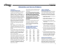
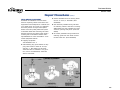
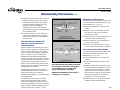
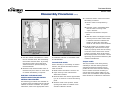
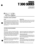
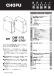
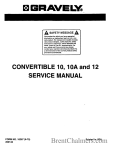
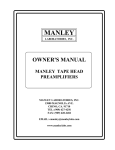
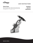
Maintenance Manual for Edward
Edward Valves
Maintenance Manual for Edward
Cast Steel Bolted Bonnet Valves
V-380 R2
Flow Control Division
Edward Valves
Table of Contents
Page
Page
KEY TO ILLUSTRATIONS .......................2
DISASSEMBLY PROCEDURES FOR
IMPACTOR HANDWHEELS .................11
INTRODUCTION TO THIS MANUAL ......3
BOLTED BONNET VALVE
FIGURE NUMBERS...............................3
SERVICE PROBLEMS
Packing Chamber leak .....................3
Packing Recommendations ................3
Bonnet Gasket Leak, Bolting Torques ..4
Seat and Disk Joint Leak ...................5
Body Wall Leak ...............................5
Objectionable Vibration, Noise or
Excessive Pressure Drop....................6
Valve Lubrication..............................6
REPAIR PROCEDURES
Valve Body Repairs
Body Bore Guide Rib Repair .............7
Seat and Disk Repairs ......................7
Body Wall Repairs ...........................8
Valve Component Repair
Disk-Piston Assembly Repairs .............9
Gasket Seal Area Repair ..................9
Welding Rod Recommendations.........9
Field Repair Equipment ...................10
DISASSEMBLY PROCEDURES FOR
BOLTED BONNET VALVES
Introduction ...................................11
First Determine the Area of Failure ...11
PROCEDURE FOR REMOVING ELECTRIC
ACTUATORS FROM VALVE BONNETS
Revolving Stem Valves ....................12
Non-Revolving Stem Valves .............12
Electric Operator Limit Switch and
Torque Switch Setting Procedures .....13
Geared Limit Switch .......................13
Torque Switch ................................13
DISASSEMBLY PROCEDURES
FOR VALVE PARTS
Stop and Stop-Check
(Non-Return) Valves ........................14
Piston Lift Check Valves...................14
KEY TO
Ill. No.
No. 1
No. 2
No. 3
No. 4
No. 5
No. 6
No. 7
ILLUSTRATIONS
Title
Page
Typical Valve Nomenclature.....5
Lapping Equipment ...............10
Impactor Handwheel
with Crossarm ......................12
Impactor Handwheel with
Adapter...............................12
Electric Operator on
Revolving Stem Valve ............13
Electric Operator on
Non-Revolving Stem Valve .....13
Piston Lift Check Valve...........14
REASSEMBLY PROCEDURES FOR
BOLTED BONNET VALVES
Introduction ...................................15
Stop and Stop-Check
(Non-Return) Valves ........................15
Piston Lift Check Valves...................15
SUPPLEMENTARY REPAIR
INFORMATION .................................15
INFORMATION REQUEST ..................12
ORDERING PARTS .............................16
2
Flow Control Division
Edward Valves
Introduction and Service Problems
Introduction
Cast Steel Bolted Bonnet
This manual has been prepared to serve as
a guide for the maintenance of Edward
bolted bonnet valve construction. It is
designed to help you in obtaining the most
satisfactory service from these valves.
Although rigid metallurgical, radiographic,
physical and visual inspection is the standard procedure for all Edward products, it
is inevitable that some valves, after a
period of time, may occasionally require
repair. When this happens, this manual
will assist you so that your valve may be
satisfactorily restored to good working
condition with a minimum of time and
expense.
Before starting, it will be helpful to have
some understanding of the valve’s physical
construction. The drawing on pg. 5 will
give you some idea of how the valve is put
together.
The next major section of this manual discusses the more common service problems
and failures. It identifies the problem and
explains the reasons for certain failures.
The reason should be understood before
work is actually started.
Then the procedure to be followed in making the repair is explained. This includes
normal valve maintenance as well as major
valve repair. Field repair equipment, available from Edward Valves, is described and
illustrated. Valve lubrication and welding
rod recommendations are also made. These
procedures are adequate for almost any
valve repair or maintenance problem that
may arise in the field.
The next major section describes the disassembly procedures for the various valve
components.
It is very important that the Introduction
and the paragraphs titled “First Determine
the Area of Failure” be read and understood before any disassembly work is
begun. Several procedures are described,
depending upon the area of failure.
Considerable time can often be saved by
first selecting the proper disassembly
procedures.
The last major section explains how the
various valve constructions are to be
reassembled. Information on how to
contact Edward Valves for additional
advice, if required, and how to order
parts is included.
FIGURE NUMBER OF EDWARD
BOLTED BONNET VALVES
DESCRIBED IN THIS MANUAL
302
302Y
303
303Y
304
304Y
318
318Y
319
319Y
328
328Y
329
329Y
390
390Y
391
391Y
392
392Y
393
393Y
394
394Y
604
604Y
605
605Y
618
618Y
619
619Y
670Y
690
690Y
691
691Y
1302
1302Y
1314
1324
1324Y
1390
1390Y
1392
1392Y
1441
1441Y
1443
1443Y
1641
1641Y
1643
1314Y
1643Y
SERVICE PROBLEMS
Packing Chamber Leak
Where moisture appears or actual dripping
occurs at the packing chamber around the
stem, gland or gland flange which cannot
be eliminated by re-torquing the gland bolt
the following points should be considered.
1. The packing may have become hard.
Replace the packing.
2. Gland travel has been fully taken up.
Repack with new packing.
3. The wrong packing is being used.
See packing recommendations shown
on this page.
4. A stem should be replaced when it
has become deeply scratched,
burred, or otherwise mutilated from
careless handling, or where the stem
has worn, tapered or has been bent.
5. The gaps in the rings of split packing
have not been staggered around the
stem. They should be inserted in this
manner.
6. The packing gland may be binding
against the packing chamber or stem
and does not compress the packing
properly. Make certain the gland fits
the packing chamber and is tightened down equally on each side.
Packing Recommendations
Edward valves are packed with all-purpose
packing sets. This is a combination of
packing using braided rings at the top and
bottom of the packing chamber and flexible graphite packing in the center section.
Packing glands should be tightened down
3
Flow Control Division
Edward Valves
Service Problems (cont.)
enough to prevent leakage but not enough
to develop excessive operating torque.
When the gland has advanced approximately half way into the packing chamber,
it in recommended that additional packing
rings be added. To obtain best results,the
stem should be thoroughly cleaned.
Replacement packing should be the same
as that originally furnished.
We recommend that replacement packing
be purchased from Edward Valves, to
assure packing with the proper density
and corrosion inhibitors is always used.
7. Apply the recommended torque to
the gland nuts evenly without cocking
the gland. See Table A for recommended torques.
8. Tighten the nuts to the initial values
shown, then loosen and re-tighten to
the final torque.
9. Stroke the valve, then re-check the
gland nut torques.
TABLE A
Long service life from modern graphitic
packing requires that adequate preloads
be applied when repacking.
1. All parts should be clean and not
scored or pitted, especially the stem.
2. The valve internal parts and bonnet
should be assembled prior to
installing the packing.
3. Position split packing rings with the
ends of adjacent rings rotated 90°.
FIGURE NUMBERS
328, 328Y,
329, 329Y,
1441, 1441Y,
1443, 1443Y
24
6
2.5
3
4
5
6
8
10
12
24
27
27
41
55
60
89
143
6
6
6
9
13
14
21
33
1302, 1302Y
1314, 1314Y
1324, 1324Y
6
8
10
12
40
68
76
140
9
16
18
32
1641, 1641Y
1643, 1643Y
2.5
24
7
604,
605,
618,
619,
2.5
3
4
5
6
27
27
41
55
60
8
8
12
16
17
302Y
303Y
304Y
318Y
319Y
4. Install in the following sequence:
Bottom Ring
–
Braided Ring
Center Rings
–
Die formed
expanded graphite
Top Ring
–
Braided Ring
5. Clean and lubricate the gland eyebolts.
6. Carefully seat each individual packing ring before adding the next ring.
INITIAL FINAL
SIZE TORQUE TORQUE
2.5
302,
303,
304,
318,
319,
604Y
605Y
618Y
619Y
A torque wrench should be used for tightening the bonnet or cover retainer studs or
cap screws which are used to preload the
soft iron gasket.
The following procedure is recommended:
1. Guard against leakage by having these
bolts tight at all times.
2. With line pressure in the valve, all nuts
or cap screws should be tightened to
the torque shown below.
Bolt diameter, Inches 1/2 9/16 5/8 3/4 7/8
GLAND BOLT TORQUES, FT-LBS
IMPORTANT:
BONNET GASKET LEAK
Torque, Ft. Lbs.
45
1
1-1/8 1-1/4
68 90 150 240 370 585 750
Should the leak fail to stop after tightening,
it must be concluded that there is an imperfect seal, and the valve will have to be
opened for examination. Such a leak may
result from either of the following causes:
1. Incomplete Seal Between Bonnet and
Gasket or Body and Gasket. An incomplete seal around the gasket seating surfaces may be caused by corrosion, dirt,
chips, or other foreign matter on the
mating surfaces. An incomplete seal
may be caused by surface imperfections
in the body or bonnet surfaces in the
form of pin holes, extended cracks, or
indentations where the metal has failed
sometime after valve installation and
use. Such imperfections may be surface
indications of deeper flaws in the body
casting which may cause a by-pass
around the gasket.
4
Flow Control Division
Edward Valves
Service Problems (cont.)
2. Leakage at the Gasket. The possibility of
a leak through the gasket itself, while
remote, should still be considered. This
may not be the result of external flaws
on the sealing surfaces of the gasket.
SEAT AND DISK JOINT LEAK
A leak existing between the seat and disk
of a closed valve might be indicated by
one of the following: a definite pressure
loss in the high-pressure side of the valve;
continued flow through an inspection drain
on the low-pressure side; or, in hot water
or steam lines, a downstream pipe that
remains hot beyond the usual length of
time and conductivity range.
steam cut, however, leakage is identified
by subdued gurgling or weakly popping
sounds. These sounds can be heard
through a stethoscope or by placing one
end of a stick against the valve body while
holding the other end between the teeth,
with hands over the ears.
BODY WALL LEAK
This is a visual leak through the body wall,
welding end or end flanges and may be
the result of a shrink cavity or other void in
the casting. If small at first, such a leak
may go unnoticed for a time, particularly if
the valve is heavily insulated and the pipe
Such a leak may be the result of a distorted seat caused by uneven welding and
stress relieving temperatures that were present in the body when mounting the valve
in the pipe line. It may also develop
because of the operator’s failure to close
the valve tightly. An increased velocity is
imparted to a flow forced through a very
small opening. This increased velocity subsequently gives rise to the “cutting” of both
disk and seat, particularly by particles of
line scale or rust in suspension or normal
solids in solution; or, in spite of the fact
that the hard surfaced material on the seat
and disk is corrosion and erosion resistant,
grooves, pit marks, or other surface irregularities may be formed on the seat and
disk joint surfaces when the disk is closed
against a foreign body on the seat. This
sometimes occurs during the initial start up
of a piping system.
Leakage of steam through a valve which is
badly steam cut has a whistling or
sonorous sound. If the valve is only slightly
5
Flow Control Division
Service Problems (cont.)
line at that point is sufficiently warm to
keep the insulation dry enough to escape
notice.
OBJECTIONABLE VIBRATION NOISE
OR EXCESSIVE PRESSURE DROP
Excessive vibration noise or humming coming from within a stop-check (non-return) or
check valve indicates the possibility that
the disk-piston assembly is wedged inside
the body. Such sticking may be caused by
uneven body guide rib wear on the downstream side induced by oversizing the
valve, by corrosion, by flakes of line scale,
or by particles of weld spatter that may
have entered the valve during construction
of the piping, and which later washed up
into the piston bearing area of the
body I.D.
The stem of a stop-check valve should
normally be fully open in order that the
disk-piston can lift the full amount. When
the disk is not touching the bottom of the
stem or the bottom stop lugs on the bonnet
(due to a wedged disk piston or insufficient
flow, for example), then the disk assembly
is free to move laterally within the body.
This motion in most cases causes a slight
vibration which can be felt through the
body, bonnet and handwheel. Screwing
the stem down slowly to contact the disk
first increases the intensity of vibration to
the hand and to the ear, but further downward movement of the stem builds up sufficient contact pressure and eliminates the
vibration. This also tends to dislodge any
foreign particles which may have been the
initial cause for disk-piston wedging.
The position of the stem where vibration
ceased, should be noted and any increase
in pressure drop indicated on available
gages, recorded. It may be that when the
stem is screwed back to the full open position, the disk will again remain in a floating position which could indicate oversizing of the valve for the flow conditions. It is
always recommended that check valve size
selection be governed by flow conditions
rather than by adjacent piping. Oversizing
induces vibration or noise and causes
excessive, uneven guide rib wear giving
rise to greater disk-piston assembly clearance on one side of the body.
Edward Valves
For valves that see frequent operation, the
lubricant should be replenished on bearings and stem threads every three months.
If extreme service conditions dictate, the
plant operating engineer should establish a
more frequent re-lube schedule.
For valves that are operated infrequently,
relubrication at least once a year is recommended. The recommended lubricant for
stem threads is Rykon EP #2, manufactured
by The American Oil Company. This is an
extreme pressure, extreme temperature
lubricant of high quality.
Another way to dislodge a wedged piston
is to use other valves in the line. If possible, vary the rate of flow through a noisy
check valve sharply enough (in a short
period of time) to dislodge the piston from
its wedged position.
LUBRICATION
In order to obtain full service life, valves
require periodic lubrication of the bearings
and stem threads, as does any rotating
machinery.
On valves where the stem bushing and
bearings are in the motor actuator, the
bearings are lubricated by the actuator
lube supply, which should by maintained
at the recommended level.
Stem threads also require periodic replenishment of the lubricant. Exposed threads
should be wiped clean of old grease and
accumulated dirt and fresh lubricant
applied. This is most effectively done with
the valve in the closed position.
6
Flow Control Division
Repair Procedures
BODY BORE GUIDE RIB REPAIR
Where more than one guide rib is
involved, each rib should be preheated
and welded before proceeding to the next.
1. Prior to any cutting or welding operations being performed on the valve, it is
necessary that adequate seat joint protection be provided and some means of
insurance against getting chips, weld
spatter or other foreign matter into the
pipe line, if the valve is permanently
mounted. A round piece of sheet metal
placed over the seat and taped in place
will furnish adequate protection.
2. Chip out the defective area in the body,
being careful to remove the affected
portion to its end, inside the casting,
and to thoroughly clean it away.
3. With a small hand grinder, grind the
chipped area smooth.
4. Heat the body area adjacent to the
guide rib to 200° Fahrenheit. This can
be done locally with an oxyacetylene
torch.
5. Select the proper welding rod to suit the
body material maximum size rod is recommended here). See Table B for weld
rod recommendations.
If replacing stainless steel inlay, use
AWS 5.4 E309L stainless electrodes.
6. The welding should be started at the
bottom so as to create a small shelf,
and then proceeded up the guide rib.
Lay the weld in thin, even layers, peening each layer before proceeding with
the next, and being careful to maintain
a temperature of 200° Fahrenheit in the
area being repaired. Peening the bead
actually stretches it and counteracts its
tendency to contract and shrink as it
cools. The last layer of weld must overlap onto the sound metal to ensure a
weld without an undercut at the edges.
The overlapping should be done along
this edge by using a welding rod of
1/8" maximum diameter. The last layer
should bring the height of the welded
area up to 1/16" above the original
surface, as checked with a straight edge
along the body bore.
For this type of weld repair, it is recommended that the last layer be pounded
while still hot with the flat face of a hammer. Thermal stress relieving is not
recommended.
7. With a hand grinder, rough grind the
welded surface to within about .010” of
the finished surface. The edges of the
guide ribs should be rounded off
smooth. Check the progress of the rough
grinding by using a straight edge and
feeler gages. As the bonnet bore and
guide rib approach alignment, a light
can be placed on one side of the
straight edge and the high spots in the
guide rib observed on the other. Where
a check valve or stop-check (non-return)
body is being repaired, the progress of
the finishing cuts can also be measured
by slipping some long pieces of shim
stock between the I.D. of the body
guide ribs and the O.D. of the disk-piston assembly, which has been placed
centrally in position on the seat joint. A
shim should pass around the disk at all
three guide ribs with equal clearance.
Edward Valves
The disk-piston assembly should also be
moved up and down to make sure that
it is free.
It is recommended that where guide rib
repairs have been made, the seat and
disk joint be checked for distortion and
relapped, if necessary.
SEAT AND DISK REPAIRS
A valve seat joint will require repairing in
any instance where the seating surface
permits a leak because it has been altered
from the original state in which it was
shipped from the factory; where corrosion
has set in to cause pit marks on the seating
surfaces of either the body or disk, where
the seat has become distorted because of
an abnormal heating condition; or, where
a groove has been formed on the seat or
disk by closing the valve against a foreign
body. Verification of such a faulty condition may be obtained by a seat bluing test
or by careful visual examination.
The hard surfaced seats in these bolted
bonnet valves are not easily scored, but
where reconditioning is necessary, the following points should be observed:
Where an indention or pit marks on the
valve seat joint are deep (.010 or greater),
a cast iron lap with suitable lapping compound will speed up repair. The cast iron
lap should be closely guided in the body
bore during the lapping.
Lap first with the cast iron lap and finish
with the valve disk, which has been
reground or relapped, if necessary. For
initial lapping, use Clover compound “A”,
Norton 320 mixed with olive oil or sperm
7
Flow Control Division
Repair Procedures (cont.)
oil to a molasses consistency is recommended for finish lapping. For rough lapping, Carborundum H20 coarse is recommended.
In the lapping operation, lap against the
seat with a small quantity of the lapping
compound placed between the mating surfaces. It is important that not too much
pressure be applied on the lap or disk
against the seat. With the lapping compound in place between the mating surface, the lap or disk should be reciprocally
rotated as far as arm movements will permit while standing in one position: the
strokes should be light, and the lap or disk
should be lifted frequently and turned to a
new position circularly around the valve
body so that lapping will be rotated over a
new area. To make certain the pressure
strokes are light, it is necessary on large
valves to suspend the disk and stem assembly from a coil spring in such a manner as
to allow the disk to bear, but lightly,
against the seat. See Fig. A pg. 10.
For smaller size valves, a driving handle
can be easily made of 3/8” diameter wire
bent as per Fig. B. These small assemblies,
being much lighter, do not require a supporting spring. Hard surfaced seating
faces are hard and lapping time is variable, depending on the extent of flaws on
the surface and the position of the valve in
the line. If a seat requires machining prior
to lapping, portable boring machines are
available from Edward Valves.
The disk of stop valves may also require
refinishing. When the only defects that can
be found on the disk-stem assembly occur
on the seating surface, it becomes very
convenient to push the stem into a lathe
spindle and chuck on the disk nut diameter
without taking the assembly apart.
(However, if the stem is too large to fit
through the lathe spindle, it will have to be
taken apart as described in the following
paragraph.) Hold the disk using a four jaw
chuck so that the large O.D. and seating
surface run true. Grind the seating surface
using a tool post grinder. Just go deep
enough to clean the surface. Polish the
seating surface with fine emery cloth.
If when checking the disk stem assembly, it
is found that the assembly is tight or does
not swivel freely, it will be necessary to
disassemble.
The lock key weld and locking key can be
drilled out. After the key has been
removed, the disk nut can be readily
unscrewed. Repair any damage surfaces
on the stem, disk nut, stem collars or disk.
Then proceed to repair the disk seating
surface as described above. When finishing the disk in this manner, it will not be
necessary to lap it to the seat.
BODY WALL REPAIRS
There are five basic steps in repairing a
casting defect:
1. Cut out to sound metal. Attempting to
weld over the defect will only leave a
notch that may re-introduce the defect.
Cutting may be done by chipping,
grinding or flame gouging. The amount
of metal removed should be held to a
minimum to avoid distortion during subsequent welding.
2. Preheat, using the minimum temperature
specified by the material specification
Edward Valves
and/or the design code. Use at least
400F on WC9 or C5 material, 300F
on WC6. Although cast carbon steels
such as WCB or WCC do not require
preheat, it may be advantageous to
remove any moisture or other contaminants from the area to be welded. This
may also identify any leak paths. There
are also disadvantages to preheat,
especially localized preheat, that must
be considered when working in areas
of the casting with finish machined
dimensions. Distortion may result in
more damaging problems than those
concerns created by the original defect.
Lower preheats and the control of interpass temperature are two methods used
to minimize distortion.
3. Welding should be done by qualified
welders, using qualified procedures and
weld material of a chemistry matching
the casting (see Table B for welding rod
recommendations). The final weld
should be blended into the contour of
the casting.
4. Stress relieving is generally recommended. Decisions to not stress relieve should
factor in piping code rules. The temperatures must be based on material specification and piping code recommendations. Again, since temperatures are
much higher than those experienced in
welding, there are also disadvantages
that must be considered. Distortion may
result in more damaging problems.
Lower temperature postweld heat treatment is sometimes an option for carbon
steels.
8
Flow Control Division
Edward Valves
Repair Procedures (cont.)
5. The final weld should receive any
needed nondestructive testing. This
should include a visual examination and
liquid penetrant or magnetic particle
examination. Some major weld repairs
could even mandate radiography to
ensure a sound weld.
VALVE COMPONENT REPAIR—
DISK-PISTON ASSEMBLY REPAIRS
It is possible that the bearing surfaces on
the O.D. of the disk-piston assembly and
I.D. of the body can become scored
deeply enough to cause a binding or
wedging of the piston assembly in a full,
or partially open or closed position. Such
scores and resulting burrs may be caused
by particles of weld spatter, flakes of hard
line scale or other foreign matter which
has inadvertently gotten into the line. Upon
disassembly burrs must be removed with
emery cloth, and the bearing surfaces
otherwise made smooth and clean again.
Where the burrs on the piston are very
large, it may be more convenient to chuck
the assembly in an engine lathe and file
them off.
GASKET SEAL AREA REPAIR
Where foreign matter of any sort is responsible for a gasket seal leak on the
sealing surface of the bonnet, it is very
likely that it has caused an impression in
the same sealing surface which must be
removed completely before reassembling.
This can be done by taking a shaving or
skin cut on the sealing surface. In so
doing, it is mandatory that the work be
chucked and square to all existing
diameters and surfaces.
TABLE B – WELDING ROD RECOMMENDATIONS
WELD ROD
RECOMMENDATIONS
MATERIAL TO BE WELDED
ASME IX
P-Numbers
Material
P-1
Carbon Steel
1. ASTM A216, Grade WCB
2. ASTM A105
AWS 5.1
E7018
P-4
1-1/4% Chromium,
1/2% Molybdenum
Low Alloy Steel
1. ASTM A217, Grade WC6
2. ASTM A182, Grade F11
AWS 5.5
E8018-B2
P-5
2-1/4 Chromium,
1% Molybdenum
Low-Alloy Steel
1. ASTM A217, Grade WC9
2. ASTM A182, Grade F22
AWS 5.5
E9018-B3
P-8
18% Chromium,
8% Nickel
Stainless Steel
1. ASTM A351, Grade CF8M
2. ASTM A182, Grade F316
AWS 5.4
E316
P-8
18% Chromium,
8% Nickel
Stainless Steel
1. ASTM A351, Grade CF8C
2. ASTM A182, Grade F347
AWS 5.4
E347
ASTM Grade
AWS Classification
WELDING EDWARD VALVES IN-LINE
When welding a valve in line, the installer
should apply the specific technical rules
imposed by the jurisdictional authority of the
area where the valve is installed, In the
absence of such rules, following are
suggested practices for welding Edward
valves in line:
1. Welding should be done using procedures
and personnel qualified in accordance with
ASME Section IX. Rules for preheat and
postheat are stated in Chapter V of ASME
B31.1 (Power Piping).
2. The valve should be welded in line, one
end at a time, in a closed position (approximately a half-turn after the seat in the body
comes in contact with the disk). This is
suggested to preclude warpage between
seating surfaces caused by temperature
induced stresses during welding or
subsequent heat treat. It also protects the
seat from weld spatter that might coat the
lapped seat and disk. When postweld heat
treat is required, each weld end should be
heat treated one at a time, to minimize
impact of heat on valve internals. Do not
heat treat an Edward valve with a piping
attached as a unit in a furnace, as
warpage of parts may occur. After welding, open the valve and flush the line to
clean out all foreign matter.
9
Flow Control Division
Edward Valves
Repair Procedures (cont.)
FIELD REPAIR EQUIPMENT
Available from Edward are some basic
tools for repairing valves in the field. This
equipment was developed for customer use
on a rental basis. Of course, an emphasis
has been placed on large valve repairs
where economics justify extensive repairs
in the field rather than removing the valve
from the pipe line for return to the factory.
Contact your local Edward Valves sales
representative for more information. A list
of this equipment follows:
3. Sunnen Portable Hone for honing bores
from 4" to 14-1/2" diameter. (Not
illustrated)
4. Van Norman portable boring machine
for reboring valves in the field. Grinding
attachments are also available for some
sizes for grinding seat joints. (Not illustrated)
5. Air driven portable boring machine for
reboring guide ribs and seats of valve
bodies in the line. (Not illustrated)
1. Lapping equipment.
See Illustration No. 2.
2. Self-centering lap guide fixtures for lapping valve seats in valves 8” and up.
See Fig. C. This fixture can be used
when the valve is installed in any position, and is recommended, when the
stem is horizontal.
10
Flow Control Division
Disassembly Procedures
DISASSEMBLY PROCEDURES FOR
BOLTED BONNET VALVES
INTRODUCTION
into two major areas. The area involved
will affect the disassembly procedure to be
followed. These areas, in general, are:
AREA 1
Step-by-step disassembly procedures are
described for all types of Edward bolted
bonnet valves, including those with manual
and motor actuators.
The impactor Handwheel or Handle, or the
Limitorque Actuator.
It is important that the following paragraphs be read and understood before
specific disassembly work is started.
The valve internals, including the bonnet,
body, stem, disk, disk-nut, gland and seats.
FIRST DETERMINE THE AREA
OF FAILURE
Failures or maintenance problems, for
other than check valves, can be divided
CAUTION
As a general reminder, make sure all pressure is removed from valves, both upstream
and downstream, before any disassembly
work is started. An exception to this is valves
requiring service only on the actuator (Area
1) where the valve can remain in service.
1. For service in Area 1.
a. If pressure is to be maintained in the
valve, fully close the valve or backseat
in full open position. On electric operated valves with non-revolving stems,
the valve must be backseated in the
full open position only.
b. If no pressure is to be maintained in
the valve, close the valve fully and
open approximately 1/8".
2. For service in Area 2.
Close the valve fully and open approximately 1/8". Service Area 2 only without pressure in the valve.
AREA 2
IF FAILURE IS INDICATED IN AREA 1,
Refer to the applicable section
“Disassembly Procedures for Impactor
Handwheels,” or “Procedures for Removing
Electric Actuators from Valve Bonnets,”
pg. 12.
IF FAILURE IS INDICATED IN AREA 2,
Two methods are available. In Method 1,
the actuator and bonnet assembly may be
removed from the valve body as a unit.
This requires less time but requires adequate clearance area above the valve. The
second method is to first remove the actuator from the bonnet, and then the bonnet
from the body, in separate steps.
For Method 1, leave the valve actuator
mounted on the bonnet and follow instructions for “Disassembly Procedures for Valve
Parts,” pg. 14.
For Method 2, first remove the operator by
following the applicable section,
“Disassembly Procedures for Impactor
Handwheels” or “Procedures for Removing
Electric Actuators from Valve Bonnets”
pg. 12. Then proceed to the section,
“Disassembly Procedures for Valve Parts,”
pg. 14.
Edward Valves
If failures are indicated in any combination
of Areas 1 & 2, then each of the respective procedures must be followed . For
check valves without stems or actuators,
simply use the proper section under
“Disassembly Procedures for Valve Parts, “
pg. 14.
DISASSEMBLY PROCEDURES FOR
IMPACTOR HANDWHEELS AREA1
Edward valves use several designs of
Impactor handles or handwheels, depending upon the valve size and pressure class.
Handwheels can be removed while the
valve is pressurized. If under pressure, the
valve should either be fully closed or backseated in the full open position.
IMPACTOR HANDLES AND
HANDWHEELS
Not illustrated, but of similar construction
to Illustration No. 4, pg. 12, are Impactor
handles. The following instructions apply,
in general, to all.
1. Remove the handwheel lock nut, which
is the uppermost part on the top of the
valve stem. On some designs, it is a friction device and is merely unscrewed.
On others, a roll pin must first be driven
out. On another design, a small lock
screw must be unscrewed.
2. Mark the relative position of the handwheel and crossarm so the original
relationship can be restored when
reassembling. If this is not done, the
handwheel could be reassembled 180°
out of the original position.
11
Flow Control Division
Disassembly Procedures (cont.)
REVOLVING STEM VALVES
3. Lift the handwheel off the valve, using a
suitable capacity chain hoist for large
handwheels. If the stem of the valve is
mounted vertically, position the hoist
directly above the handwheel,
Otherwise, the hoist should be positioned slightly away from the handwheel
in line with the stem.
On revolving stem valves the actuator drive
nut is connected to the stem through a key.
See Illustration No. 5, pg. 13.
1. Disconnect the electrical wiring to the
actuator.
2. Position a sling on the motor actuator
and attach a chain hoist of suitable
capacity to the sling.
4. Crossarm Removal: For all valves, the
crossarm can be removed by tapping
lightly with a hammer on the underside
and lifting off.
3. Remove the nuts or cap screws from the
underside of the actuator flange.
4. Lift the actuator up and completely off
the stem and stem key.
PROCEDURES FOR REMOVING
ELECTRIC ACTUATORS FROM
VALVE BONNETS
Edward bolted bonnet valves use various
types of electric actuators, depending upon
the size and pressure class, which determine the torque requirements, whether the
stem is revolving or non-revolving and
whether the valve takes the stem thrust
(torque only unit) or the actuator takes the
stem thrust (torque and thrust unit). The procedures below describe the removal of
these various types from the valve bonnet.
Also included are complete instructions for
resetting the limit switches.
Disassembly procedures for the electric
actuators themselves are not included and
appropriate instructions should be
obtained before starting. Consult the actuator manufacturer.
The actuator can be removed while the
valve is pressurized but caution must be
observed to make certain that the valve is
first in the backseated or fully open position
before removing units from valves with nonrevolving stems. See “Caution, “pg. 11.
Edward Valves
5. Position the actuator away to a clean
area for further disassembly, if required.
NON-REVOLVING STEM VALVES
On non-revolving stem valves, the actuator
drive nut is threaded to the stem. See
Illustration No. 6, pg. 13.
1. Disconnect the electrical wiring to the
actuator.
All of the following disassembly procedures
are arranged in accordance with the general comments of pg. 11. Study these
pages carefully before beginning.
Determine first whether the valve stem is
revolving or non-revolving.
2. Make certain the packing gland nuts
are tight.
3. Position a chain hoist of suitable capacity so the actuator is supported in such a
manner that the handwheel can still be
rotated. If the valve is installed with its
stem other than vertical, the hoist should
be positioned slightly away from the
handwheel in line with the stem.
4. Remove the nuts of cap screws from the
underside of the actuator flange.
12
Flow Control Division
Edward Valves
Disassembly Procedures (cont.)
5. Connect the electric current and check
this setting as follows:
a. Run the valve to mid-position by
hand.
b. Press the “open” push button-make
sure the valve is moving in the
“open” direction.
c. Allow the limit switch to stop the
motor.
d. After the motor has stopped, turn the
valve by hand to make certain there
is sufficient clearance between the
position at which the valve stem
comes to rest and the valve backseat.
5. Turn the actuator handwheel in a direction to close the valve, thus unscrewing
the actuator from the stem. Try to keep
the weight on the hoist as the handwheel is turned to prevent damage to
the stem threads.
6. With the hoist, lift the actuator clear of
the stem and place down on clean area
for further disassembly, if required.
ELECTRIC ACTUATOR LIMIT
SWITCH AND TORQUE SWITCH
SETTING PROCEDURES
The following procedures are intended as
a general guide for setting limit and torque
switches on electric actuators. For specific
instructions, refer to the appropriate actua-
tor instruction manual or consult the actuator manufacturer.
Geared Limit Switch
When mounting or re-mounting an electric
actuator, the geared limit switch must be
reset as follows:
1. Make certain the electric current is off.
2. Open valve by hand until the stem
strikes the backseat.
3. Mark the stem and reclose approximately 1/8” to allow for coast of the moving
parts.
4. With the valve in this position, set the
opening limit switch as outlined in the
actuator instruction manual.
6. To set the position for operation of the
indicating light, make sure the torque
switch is properly wired into the closing
circuit and run the valve to the closed
position. Back the valve off the seat to
the desired position and set the “closed”
light using the procedure outlined by the
actuator manufacturer.
Torque switch
The torque switch is set during factory
assembly to seat the valve against the
specified unbalanced pressure and to
protect the valve from excessive seating
forces. Should it become necessary to
change the torque switch setting for any
reason, the local Edward Valves representative should be contacted for instructions.
13
Flow Control Division
Disassembly Procedures (cont.)
DISASSEMBLY PROCEDURES FOR
VALVE PARTS AREA 2
(For a definition of Area 2, see pg. 11.)
(See Illustration No. 1, pg. 5, for an explanation of valve parts nomenclature.)
Step-by-step disassembly procedures are
described below. The procedures include
disassembly instructions for stop, stopcheck (non-return), and piston lift check
valves. The applicable instructions should
be read thoroughly before the start of disassembly.
All of the following bonnet disassembly
procedures are arranged in accordance
with the general comments on pg. 11.
Study these pages carefully before
beginning.
STOP AND STOP-CHECK
(NON-RETURN) VALVES
See Illustration No. 1, pg. 5.
tive that they be placed carefully on a
bed of rags or other soft material to
avoid marring any machined surface,
particularly any seating and sealing surfaces.
5. Unscrew the stem from the bonnet bushing.
6. On stop valves, the disk and disk-nut
assembly is attached to the stem. On
stop-check (non-return) valves, the piston
disk assembly is not attached to the
stem and must be removed separately.
See Step 7.
7. Screw 3/8 – 16 UNC bolts (1/2 – 13
UNC on 12" valve) into the threaded
bosses or nuts provided in the piston.
The piston now can be lifted from the
valve. Occasionally, a vacuum may be
formed by the cooling fluid in the pipe
line below the valve. Until relieved, this
vacuum will prevent removal of the piston.
1. Loosen the packing gland bolt nuts and
tap the gland which should relieve any
pressure which might be trapped in the
valve. This is important.
8. The bonnet end opening should be kept
covered whenever possible.
2. Carefully remove the bonnet stud nuts or
cap screws.
See Illustration No. 7.
3. Remove the packing gland bolts nuts.
4. Use a chain hoist in line with the stem to
lift the stem-bonnet assembly out of the
body. During this process, mark the
body bonnet, and gasket at corresponding points (other than sealing surfaces)
so that their relative position can be
duplicated in reassembly. In laying the
parts aside for inspection, it is impera-
Edward Valves
1. Carefully remove the cover nuts or cap
screws observing the above caution.
2. Lift the cover off the valve. During the
process, mark the body, cover and gasket at corresponding points (but not on
the sealing surfaces) for reference and
reassembly. In laying the parts aside for
inspection, it is imperative that they be
placed carefully on a bed of rags or
other soft material to avoid marring any
machined surface, particularly any seating and sealing surfaces.
3. Screw 3/8 – 16 UNC bolts (1/2 – 3
UNC on 12" valve) into the threaded
bosses or nuts provided in the piston.
the piston now can be lifted from the
valve. Occasionally, a vacuum may be
formed by the cooling fluid in the pipe
line below the valve. Until relieved, this
vacuum will prevent removal of the piston.
PISTON LIFT CHECK VALVES
Piston lift check valves are constructed with
valve bodies similar to the corresponding
stop or stop-check (non-return type valves.
Disassembly is simplified by the absence of
a yoke and stem.
NOTE: Care must be taken in removing the
cover bolting in case pressure should be
trapped in the body (downstream piping).
Check to make certain all downstream
pressure is relieved.
14
Flow Control Division
Edward Valves
Reassembly Procedures
4. The bonnet end opening should be kept
covered when ever possible.
STOP AND STOP-CHECK
(NON-RETURN VALVES)
SUPPLEMENTARY REPAIR
INFORMATION
REASSEMBLY PROCEDURE FOR
BOLTED BONNET VALVES
See Illustration No. 1, pg. 5.
In analyzing valve trouble in the field, it is
important to consider the following factors:
INTRODUCTION
The reassembly procedures in this manual
are not as detailed as the disassembly
instructions since, in many cases, just a
reverse procedure is used. However, stepby-step instructions are provided. In addition, the following general points should
be considered.
1. The most important consideration in the
reassembly of valves is cleanliness. All
loose scale should be removed with a
wire brush, emery cloth, or acid solvent.
Oil and grease should be removed from
all parts with a suitable solvent to prevent any foreign matter from collecting
on sealing seating surfaces.
2. Unless it is impossible to do so, use a
new gasket when reassembling a
bonnet which has been disassembled
whether it was leaking or not.
1. Insert the disk, disk-nut, stem assembly,
or the disk-piston and stem, lowering
carefully until they rest on the valve seat.
Hold the stem centrally in the valve
bore.
2. Install a new gasket on the body.
3. Lower the bonnet into position, rotating
the stem as necessary to engage the
yoke bushing threads.
4. Install and tighten the bonnet stud nuts
of cap screws in accordance with the
torque values shown on pg. 4. All nuts
or cap screws must be tightened uniformly in a star pattern to avoid cocking
the bonnet.
5. Reassemble the actuator to the valve
using a procedure opposite the disassembly.
PISTON LIFT CHECK VALVES
See Illustration No. 7, pg. 14.
3. When reassembling valve bonnets,
always examine stem packing and
replace if necessary.
1. Insert the disk-piston, lowering it carefully until it rests on the valve seat.
4. Observe all of the reference marks or
prick punch marks assigned during
disassembly so that the original part
relationships can be maintained.
3. Lower the cover carefully onto the valve.
2. Install a new gasket on the body.
4. Install and tighten the cover stud nuts or
cap screws in accordance with the
torque values shown on pg. 4. All nuts
or cap screws should be tightened uniformly in a star pattern to avoid cocking
the cover.
1. Size of the valve.
2. Figure number of the valve.
3. Lot number of the valve.
4. Service (water, oil, gas, super-heated
steam, etc.).
5. Operating pressure and temperature.
6. Direction of flow through stop valves
(inlet pressure above the disk or below
the disk)
7. Rate of flow through the valve (lbs. per
hour or gallons per minute).
8. At what pressure, temperature of flow
rate does the reported trouble occur.
9. Pressure drop across the valve.
INFORMATION REQUEST
If the maintenance problem looks particularly difficult, it is suggested that you contact your local Edward Valves representative. He is familiar with these maintenance
instructions and has a variety of engineering data sheets. In all communications with
your local representative concerning difficulties, mention the valve size, figure number, lot number (if one is given) and as
many of the nine conditions listed above
as possible. Some of this information is
found on the nameplate attached to the
valve bonnet.
15
Flow Control Division
General Information
WARNING
Edward valves are not provided with a
pressure relief device. A pressure relief
device must be provided elsewhere in the
piping system to prevent the piping system
pressure from exceeding the maximum
rated pressure of the valve.
WELDING VALVES INTO PIPING
Welding is outside the scope of this manual, but Edward recommends you consult the
appropriate welding procedure in
ASME/ANSI B31, or whatever other codes
apply to your system. When welding valves
into piping, make sure there is no foreign
material on the seat joint, then close the
valve tightly to avoid distorting the seats.
During subsequent stress relief of the welds,
leave the valve closed to avoid distorting
the valve seat. Also, during stress relief,
assure that the valve upperstructure is not
overheated. After welding and stress relief,
open the valve and flush the line to clean
out all foreign matter.
PIPING SUPPORT
Piping should be supported sufficiently to
preclude excessive end loads on the valve.
VALVE INSTALLATION GUIDELINES
Except as noted below, Edward stop valves
can be installed in any position. Installed
positions with the valve cover or bonnet
below horizontal, where dirt and scale can
accumulate in the valve neck, should be
avoided. The orientation limits shown in
Figures 1 and 2 must not be exceeded for
Edward Stop-Check valves and Check
valves. The limitations given for line inclination and bonnet roll angle should not be
combined.
All Check and Stop-Check valves should be
installed with 10 or more diameters of
straight pipe upstream of the valve to minimize flow disturbances. For additional
information, refer to the “Technical” section
of the Edward Valves Catalog, Publication
No. EV-100.
NOTES ON VALVE OPERATION
Valves equipped with electric motor actuators have special tags attached which indicate the correct torque switch setting for the
valve. Exceeding these torque switch settings can cause damage to the valve.
Never use an electric motor actuator to
backseat a valve. This can result in damage
to the valve stem and bonnet backseat.
Edward Valves
clean of old grease and accumulated dirt.
Fresh lubricant should then be applied. This
is most effectively done with the valve in the
closed position. For valves that see frequent
operation, such as motor actuated valves,
the lubricant should be replenished every
three months. If extreme service conditions
dictate, a more frequent relube schedule
is recommended. The recommended
lubricant for all stem threads is Rykon
EP #2, manufactured by the American Oil
Company. This is an extreme pressure,
extreme temperature lubricant of high
quality. For valves that are operated
infrequently, relubrication should be at
least once a year.
NOTES ON VALVE MAINTENANCE
When replacing the bonnet gasket in
Edward valves, follow the torque requirements on page 4 closely. Failure to torque
the bonnet bolting properly will result in
gasket failure. When replacing the valve
stem packing, never machine the packing
chamber oversize. This will result in
blowout of the packing.
LUBRICATION
In order to obtain full service life, valves
require periodic lubrication of the stem
threads. Exposed threads should be wiped
16
Flow Control Division
Edward Valves
General Information
SEAT AND DISK JOINT LEAKS
A leak existing between the seat and disk of
a closed valve might be indicated by one of
the following: a definite pressure loss in the
high-pressure side of the valve; continued
flow through an inspection drain on the lowpressure side; or, in hot water or steam
lines, a downstream pipe that remains hot
beyond the usual length of time and conductivity range. Such a leak may by the result
of closing on dirt, scale or other foreign
matter in the line. It may also develop
because of the operator’s failure to close the
valve tightly. An increased velocity is imparted to a flow forced through a very small
opening. This increased velocity subsequently gives rise to the “cutting” of both disk
Figure 1
45° Inclined Bonnet Piston Lift Check Valves
Maximum Check Valve Orientation Limits
and seat, particularly by particles of line
scale or rust in suspension or normal solids
in solution. In spite of the fact that the hard
surfaced material on the seat and disk is
corrosion and erosion resistant, grooves, pit
marks, or other surface irregularities may be
formed on the seat and disk joint surfaces
when the disk is closed against a foreign
body on the seat. This sometimes occurs
during the initial start up of a piping system.
Leakage of steam through a valve which is
badly steam cut has a whistling or sonorous
sound. If the valve is only slightly steam cut,
however, leakage is identified by subdued
gurgling or weakly popping sounds. These
sounds can be heard through a stethoscope
or by placing one end of a stick against the
Figure 3
Angle Piston Lift Check Valves
Orientation Limits
valve body while holding the other end
between the teeth, with hands over the ears.
HOW TO ORDER PARTS
During normal working hours, call
800-225-6989 or 919-832-0525. To assure
the correct parts for your Univalve®, include
the valve size, the figure number - including
any prefix and/or suffixes and if available,
the B/M number. All nuclear valves require
the B/M number to properly identify your
Univalve. This information is located on the
valve nameplate. The nameplate is attached
to a yoke leg via a cable. If the nameplate
is inaccessible, you can use your Edward
sales drawing; please include the drawing
number as well.
Figure 4
Tilting Disk Check Valves
Orientation Limits
Figure 2
90° Bonnet Piston Lift Check Valves
Maximum Valve Orientation Limits
17
Flow Control Division
Notes
Edward Valves
18
Flow Control Division
Notes
Edward Valves
19
Flow Control Division
Edward Valves
Flowserve Corporation has established industry leadership in the design and manufacture of its products. When properly selected, this Flowserve product is designed to perform its intended function safely during its useful life.
However, the purchaser or user of Flowserve products should be aware that Flowserve products might be used in numerous applications under a wide variety of industrial service conditions. Although Flowserve can (and often does)
provide general guidelines, it cannot provide specific data and warnings for all possible applications. The purchaser/user must therefore assume the ultimate responsibility for the proper sizing and selection, installation, operation,
and maintenance of Flowserve products. The purchaser/user should read and understand the Installation Operation Maintenance (IOM) instructions included with the product, and train its employees and contractors in the safe use of
Flowserve products in connection with the specific application.
While the information and specifications contained in this literature are believed to be accurate, they are supplied for informative purposes only and should not be considered certified or as a guarantee of satisfactory results by
reliance thereon. Nothing contained herein is to be construed as a warranty or guarantee, express or implied, regarding any matter with respect to this product. Because Flowserve is continually improving and upgrading its product
design, the specifications, dimensions and information contained herein are subject to change without notice. Should any question arise concerning these provisions, the purchaser/user should contact Flowserve Corporation at any
one of its worldwide operations or offices.
For more information about Flowserve Corporation, contact www.flowserve.com or call USA 1-800-225-6989.
FLOWSERVE CORPORATION
FLOW CONTROL DIVISION
Edward Valves
1900 South Saunders Street
Raleigh, NC 27603 USA
Toll- Free Telephone Service
(U. S. and Canada)
Day: 1-800-225-6989
After Hours Customer Service
1-800-543-3927
US Sales Offices
Phone:
919-832-0525
Facsimile: 919-831-3369
Facsimile: 919-831-3376
Visit Our Website
www.edwardvalves.com
© 2003 Flowserve Corporation, Irving, Texas, USA. Flowserve and Edward Valves are registered trademarks of Flowserve Corporation.
V-380 R2 3/03 Printed in USA