1
Operating Instructions
OS3 Base unit, VC830100
VV016011E
Phaco Emulsification System
0297
29.05.09
VV016011E
1
Operating Instructions OS3 Base unit, VC830100
Contents
1
2
3
3.1
4
5
5.1
6
6.1
6.2
6.3
6.3.1
6.3.2
7
7.1
7.2
7.3
8
8.1
8.2
8.2.1
8.2.2
8.2.3
8.2.4
8.2.5
8.2.6
8.3
8.3.1
8.3.2
8.3.3
8.3.4
8.3.5
8.3.6
8.3.7
8.4
8.5
8.5.1
8.5.2
8.6
9
9.1
9.2
9.3
10
11
12
12.1
12.2
12.3
13
14
15
16
17
18
19
20
29.05.09
Page
3
3
4
Application and description
Points to note and hazards
Control panel
Arrangement of control and indicator elements
4
Control pedal
Mains connection / switching the unit on/off
6
8
Replacing fuses
8
Setting up the I/A system
8
Installing the cassette
Filling the I/A system (PREOP)
Removing and cleaning the cassette
Cassettes for single use (Fig. 3,4)
Autoclavable cassette fig. 5 (the instructions on the accompanying packaging insert are binding)
9
10
10
10
10
Attaching the operating instruments
11
Suction/rinsing instrument
Ultrasonic phaco handpiece
Diathermy instruments
11
11
12
Operating the unit
12
Storing values (multimode memory)
I/A
I/A operation
Changing between venturi/peristaltic operation
Infusion pressure IOP
Continuous irrigation
Reflux
Proportional Override
Ultrasonic phaco
Phaco test
Phaco operation
Phaco pulse and phaco burst
CMP Phaco
Occlusion Mode Phaco
Proportional override for Phaco
Setting of values for additional aspiration and phaco-power in DUALLINEAR 2 mode
Diathermy
HF CUT
Capsulotomy
Glaucoma
Vitrectomy
12
13
13
13
13
14
14
14
14
14
14
15
15
15
15
16
16
16
16
16
17
System communication
17
Visual displays
Acoustic signals
Voice confirmation
17
17
17
Pre-settings using ParaProg
Selection of setting values
Cleaning and sterilisation regulations
18
18
19
Cleaning the Control Device
Cleaning the Instruments
Sterilisation
19
19
19
Accessories and replacement parts
Authorised service centres
Technical data
Overview of messages, warnings and error messages
Symbols
Calibration and maintenance
Disposal
OS3 Base Unit, VC830100, Overview
19
19
20
21
22
22
22
23
VV016011E
2
1
Application and description
The OS3 operating unit is used in surgical procedures to the
anterior and posterior segments of the eye. It performs all
essential functions including irrigation and aspiration,
ultrasound Phaco, bipolar diathermy for haemostasis and
coaptation of conjunctiva, diathermic capsulotomy, diathermic
tissue cutting and the drive of vitrectomy instruments. The
unit can be supplemented with the VC830200 module for
carrying out vitreo-retinal procedures.
The unit actuates and controls companion instrumentation
within the performance limits chosen by the operator and as
set on the control panel. A foot pedal effects fine adjustments
within the pre-set limits. The unit is extremely easy to use.
Frequently used equipment settings can be stored and
recalled.
The unit may only be used with the Oertli instruments
recommended and supplied by the manufacturer (see
Section 13).
The unit may only be operated by trained personal. Correct
settings are the responsibility of the surgeon.
The unit is not suitable for surgical procedures outside the
eye. If in doubt, contact the manufacturer.
2
Points to note and hazards
IMPORTANT!
1. Patients with heart pacemakers or pacemaker electrodes
may be at risk in that the functioning of the pacemaker may
be impaired or the pacemaker itself damaged. If in doubt, the
cardiology department must be consulted.
2. The functioning of other electro-medical equipment may be
affected during the operation of bipolar diathermy,
capsulotomy and vitrectomy cutters.
IMPORTANT!
Where high-frequency diathermy, HF-cut or vitreous cutting is
used simultaneously with physiological monitoring equipment
on the same patient, any monitoring electrodes must be
placed as far as possible from the diathermy points. Needle
monitoring electrodes are not recommended. Monitoring
systems incorporating high-frequency current limiting devices
are recommended in all cases.
IMPORTANT!
The correct choice of instrument settings is the responsibility
of the surgeon! Values given in this instruction manual are
suggestions only.
IMPORTANT!
Only instruments and accessories supplied by the
manufacturer and listed in Section 13 may be used!
IMPORTANT!
Only persons authorised by the manufacturer may carry out
modifications and repairs, otherwise the proper functioning of
the unit may be impaired.
IMPORTANT
Please read these instructions very carefully before using the
apparatus for the first time!
IMPORTANT!
Before connecting the unit, check that the voltage shown on
the rating plate is the same as that of the operating room!
IMPORTANT!
While operating in diathermy or HF-cut mode, the instrument
tip must be monitored carefully. The pedal must be released
immediately as soon as tissue begins to overheat
excessively.
IMPORTANT!
All accessories must be checked regularly! Diathermy cables
in particular should be checked for possible damage to the
insulation.
IMPORTANT!
The unit must never be used in areas containing inflammable
anaesthetics!
IMPORTANT!
The cart with the tray fully stretched out can tip over if
inclined more than 6°! The cart must only be moved when the
tray is fully folded and stored.
IMPORTANT!
The operator is responsible for compliance with EN ISO
60601-1:2007.
29.05.09
VV016011E
3
3
Control panel
The display and adjustment area
All settings for the operation of the OS3 operating unit can be
undertaken using the control panel (pre-settings are made
using ParaProg. See Section 10). Visual displays serve to
show the current operating state of the unit and the current
values. The buttons respond to light pressure, which can also
be applied using a sterile swab or the special sterile operating
pen (VE850003) available from the manufacturer.
Depending on the stage of the operation or the setting of the
operating pedal, certain buttons will be blocked. This feature
offers increased protection against improper use.
The execution of a button command is accompanied by
corresponding changes in the display field. There is no
change in the display when a blocked button is pressed.
Function display
Value display
Surgeon display
The function display
Shows which function has been selected and is active. The
display matches the symbol on the function button last
pressed. Any auxiliary functions selected are also indicated:
PULS by a P, Burst by a B, CMP by CMP and IRR by a
falling droplet.
The control panel can be separated from the unit and placed
in a sterile bag for use in the sterile area. To do so, lift and
disengage the control panel from below. Alternatively, an
additional control panel VE 830025 or a remote controller VE
830020 can be connected to socket M3.
The value display
Shows the limit value selected for the instrument being used
(or the current value when the pedal is depressed).
3.1 Arrangement of control and indicator elements
Vitrectomy:
Phaco:
Displays and
settings for
operation
functions
Diathermy:
HF CUT:
Power in %
GLAUCOMA or CAPSULE (no indication of
power as automatic controlled)
Number of cuts per minute
Power in % and elapsed ultrasound time
(relative to power)
The surgeon display
Shows the number of the selected surgeon memory or name
of the surgeon.
Arrow buttons
The arrow buttons can be used to reduce (down arrow) or
increase (up arrow) the value display in the panel
immediately above. Press normally to change the values
slowly or in single steps, and depress fully to change the
values quickly.
0:00 button
If the two arrow buttons are pressed simultaneously,
ultrasound time is reset to 0.
Displays and settings
I/A system
Auxiliary functions
PEDAL light indicator
Lights up green when the pedal is active. Certain control
elements are then blocked for safety reasons.
The controls and displays are grouped in such a way that the
unit can be operated after just a short familia- rization period,
even in semi-darkness. The top half of the control panel is the
display and adjustment area for the phaco, vitrectomy,
diathermy and capsulotomy functions. It shows at a glance
the operating state of the unit and the current values. The
values displayed can be increased or decreased using the
dark green arrow buttons immediately beneath the display.
The lower half of the control panel houses the displays and
adjustment buttons for the irrigation/aspiration system.
The lowest row on the control panel contains all the buttons
for the auxiliary functions.
Please familiarise yourself thoroughly with this ergonomic
arrangement of the control elements; it will quickly enable you
to operate the unit almost "blind"!
29.05.09
VV016011E
4
OCC-M button and light indicator
The OCC-M function is switched on and off by light pressure
to the button. Pressing the button more forcibly prepares the
OCC-M memory for programming (see 8.3.4).
Light indicator on:
Slow flashing:
Rapid flashing:
OCC-M function ready
OCC-M memory ready for programming
OCC-M function active
(see 8.3.3).
In ParaProg you can specify per surgeon whether Pulse or burst or pulse and
burst shall be available.
I/A system
Flow indicator
Suction-(vacuum)
indicator
IOP indicator
Function selection area
DIA button
Sets the unit to DIATHERMY function at the output last
selected.
HF CUT button
Sets the unit to the CAPSULE (capsulotomy) or GLAUCOMA
(as last selected) function with automatic output control.
VIT A button
Sets the unit to VITRECTOMY function, to operate the
vitrectomy instruments connected to the VIT A port and using
the values selected for cut rate, flow and suction.
VIT B button
Sets the unit to VITRECTOMY function, to operate the
vitrectomy instruments connected to the VIT B port and using
the values selected for cut rate, flow and suction.
VIT PN button
Sets the unit to VITRECTOMY function, to operate the
vitrectomy instruments connected to the VIT PN port and
using the values selected for cut rate, flow and suction.
PHACO1 button
Sets the unit to ultrasonic phaco or CMP (as last selected)
function, Program 1, with the values stored in this program.
PHACO2 button
Sets the unit to ultrasonic phaco or CMP (as last selected)
function, Program 2, with the values stored in this program.
PHACO3 button
Sets the unit to ultrasonic phaco function or CMP (as last
selected), Program 3, with the values stored in this program.
Flow indicator
In peristaltic mode, this shows the maximum set aspiration
flow rate (or the current rate if the pedal is depressed). In
venturi operation, it indicates the set venturi speed (100% =
immediate creation of vacuum), also called the venturi effect.
Suction (vacuum) indicator
Shows the set limit value for suction (vacuum). The current
value is shown if the pedal is depressed.
IOP indicator
Shows the current bottle height in cm. If used in conjunction
with Vitrex module VC830200, the air pump pressure (AIR
function) can also be indicated here. Press the IOP button on
the Vitrex unit to do this.
I/A1 button
Sets the unit to irrigation/aspiration function, Program 1, with
the respective stored values for flow rate (or venturi speed)
and suction.
I/A2 button
Sets the unit to irrigation/aspiration function, Program 2, with
the respective stored values for flow rate (or venturi speed)
and suction.
I/A3 button
Sets the unit to irrigation/aspiration function, Program 3, with
the respective stored values for flow rate (or venturi speed)
and suction.
CMP button
Switches on CMP operation (for phaco 1, 2, 3) and switches
it off when the CMP button is pressed again. If the button is
held down, CMP frequency and cooling factor can be
changed (see 8.3.4).
IRR button and light indicator
Switches on the continuous irrigation function, and switches it
off if pressed again. When the light indicator is illuminated:
the IRR function is ready (see 8.2.4). If the button is held
down, the irrigation valve remains open.
PULSE button
Switches on pulse or burst operation (for phaco 1, 2, 3) and
switches it off when the button is pressed again. If the button
is held down, the pulse or burst parameters can be changed
Venturi button and light indicator
Switches between the peristaltic and venturi pump. When the
light indicator is illuminated: the venturi pump is ready (see
8.2.2).
29.05.09
VV016011E
5
Auxiliary functions
The vertical range – from zero to the fully depressed position
– is divided into a maximum of three ranges: irrigation,
aspiration and instrument activation. These three ranges lie
between positions 0, 1, 2 and 3. If the pedal is pressed
slowly, the settings 0-3 can be felt as a slight resistance. This
resistance can be changed in ParaProg (low, medium, high).
RESET button
Can be pressed at any time, and brings the unit to an
immediate stop. Ultrasound time is reset to zero. Reset of the
Ultrasound time also after installation of the cassette.
The RESET button restarts the internal processor and is thus
an escape button in a situation where, for some reason,
normal operation is no longer possible.
AUX button
Used (button held down) to adjust the volume of acoustic
signals (SOUND) and voice messages (VOICE). Also adjusts
the IOP indicator (bottle height).
VOICE button
Repeats or stops the current voice message. The scope of
information given can be defined in ParaProg.
PREOP button
Initiates the filling and rinsing function, and stops the
procedure if pressed again. Completes the procedure with a
phaco test if PREOP is started when in phaco 1, 2, 3
operating mode.
TEST button
Starts the phaco test when the unit is set to phaco 1, 2 or 3,
or activates the connected vitrectomy instrument during
button depression, if the unit is in VIT A, VIT B or VIT PN
mode.
NOTE: If not willingly activated PREOP or Phacotest also
can be interrupted by pressing pedal with the heel.
Then the display shows the message “PREOP
discontinued” or “Phaco Test discontinued”.
4
The number of positions and the amount of travel between
them can be changed in ParaProg. This is described in detail
in the ParaProg user manual, VV016013E.
The vacuum is always off in position 0.There is no suction,
and the instruments are inactive.
The service engineer can adjust the firmness of the pedal
(resistance to movement).
The horizontal plane
In the horizontal plane, the pedal can be moved to the left
and right. The pedal can be moved horizontally from any of
the vertical positions, i.e. even when the pedal is depressed.
If duallinear operation is selected in ParaProg (see Section
10), the chosen instrument is controlled linearly by moving
the pedal to the left (i.e. the power of the instrument
changes in proportion to the deflection).
Moving the pedal to the right switches between the
multimode memories of the function just used (e.g. phaco 12-3 etc.).
ParaProg (see Section 10) can be used to specify whether 2
or 3 memories should be available.
In ParaProg (se Section 10) you can invert the assignments
of left and right of the horizontal movement to right and left.
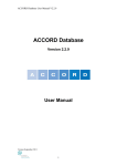
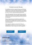
Control pedal
The control panel is used to regulate the I/A system and all
instruments. It must be connected to the pedal connection
socket (M1) on the rear of the unit. The control pedal can be
moved vertically (downwards) and
horizontally (sideways) and has four switching elements,
which, for safety reasons, can only be accessed by lifting the
foot.
The vertical plane
Fig. 1
4
Reflux
The pedal is brought to position 4 by pressing with the heel,
and this position is always used to activate reflux.
0
Switching elements
The two round switches (heel switches) can be operated with
the heel (the pedal does not have to be in the zero position)
to change the infusion pressure (bottle height) or air pump
pressure. Pressure is always reduced with the left heel
switch, and increased with the right heel switch.
The two switches on the pedal grip (TOP switch) are
positioned so that they can only be activated after the pedal
has been returned to the zero position (foot raised).
TOP left
Switches between the basic functions (selector) e.g. I/A,
CAPS, Phaco, etc. Each surgeon can enter his preferred
sequence in ParaProg.
1
2
3
29.05.09
VV016011E
6
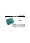
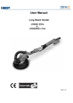
Fig. 2
Overview of the pedal controls
Pos. 3 Instrument (Phaco, VIT, DIA, CAPS, Override)
Pos. 2 ASP
Pos. 1 IRR
Pos. 0
Forwards
Sideways, left +
Linear instrument control
Aspiraton*
Phaco*
VIT*
DIA LOW (linear)
CAPS REGULAR (fix)
VISCO INJECTION (linear)
Reflux****
Sideways, right
Top left
Top right
Selector**
Venturi-Peristaltic
or AIR on/off
Instant diathermy
Pulse on/off (linear phaco)
Heel left
I/A 1-2-3
Phaco 1-2-3 or Pulse on/off*
VIT A-B-PN or Cut-SC***
DIA HIGH (linear)
CAPS HIGH (fix)
VISCO EXTRACTION (linear)
Heel right
Bottle lower
or
AIR 3-2-1
or decrease
AIR pressure
Backwards
REFLUX
IRR off
Bottle higher
or
AIR 1-2-3
or increase
AIR pressure
* Only when 'duallinear' has been selected in ParaProg
** Allows you to change between the basic functions
*** Single cut or scissors close
**** Only when selected in ParaProg
+ Unless left and right are inverted in ParaProg (INVERT)
TOP right
Switches between the venturi and peristaltic pump.
Alternatively, in ParaProg this switch can also be set to
switch the air pump on/off.
NOTE: If the Venturi cassette VV635010 is being used, the right TOP switch is
automatically set to air pump AIR
29.05.09
VV016011E
7
5
Mains connection / switching the unit on/off
IMPORTANT!
The mains voltage in the operating area must be
100...240VAC / 50...60Hz!
O
P
6
Setting up the I/A system
With the exception of diathermy and capsulotomy, a properly
set up and filled irrigation/aspiration system is essential for all
operations.
IMPORTANT!
To ensure trouble-free operation, the I/A system must be
completely filled with irrigation fluid. The tubes must be
completely free of air bubbles!
Q
The OS3 unit cassette system simplifies the proper set-up of
the I/A unit. Three different designs are available.
Plug the supplied mains cable into the mains connection
socket O on the back of the unit, and connect to the mains
supply socket.
Move the power switch Q to position I.
As soon as it is switched on, the unit starts a self test
(AUTOTEST), and checks the functioning of the switching
circuits, voltages, tone generation, instrument drives and
pump.
If the pedal is not connected, the message "NO PEDAL"
appears.
When the test has been completed successfully, the
message "SELECT SURGEON" is displayed.
Fig. 3
VV630010 Single use
VV630011A Single use Phaco Pack
The selected surgeon memory appears in the surgeon
display. It can be changed by using the arrow buttons.
In the flow display, the version of the installed software
appears in weakly illuminated lettering.
The unit is now ready and can be prepared for the operation.
5.1 Replacing fuses
Press the clip on fuse holder P to the right, until it pops out.
Use a small screw driver as desired. Fully pull out holder.
Insert new fuses and push in the holder P again.
The correct fuse value is printed above the holder P on the
rear panel of the unit.
Fig. 4
29.05.09
VV016011E
VV635010 Single use; venturi only; with
second aspiration connection.
8
6.1 Installing the cassette
IMPORTANT!
Ensure that conditions are sterile when installing the tubing
system!
The ends of the instrument connection tubes must be kept in
the sterile area. The sterile person must not insert the tubes
into the unit!
Turn the cassette rotary switch in an anti-clockwise
direction and open the cassette door G1 downwards.
IMPORTANT!
Do not reach into the cassette opening (risk of injury!) Never
insert any kind of tool into the cassette opening (risk of
damage!)
Fig. 5
1
2
3
3a
4
5
5b
6
7
8
VV630003 Autoclavable
Infusion connection IRR
Aspiration connection ASP1
Connection for infusion bottle BSS
Protective cap
Emergency discharge
Aspiration connection ASP2
Protective cap
Screw cap for discharge
Venturi opening
Rinsing tube
Insert the cassette in the cassette opening (with the
tubes facing the operator). Lightly bend the tubes to the
right with the right hand, and use the left hand to close
the cassette door by pushing it upwards. Turn the
cassette rotary switch G in a clockwise direction until you
hear and feel it engage (horizontal position). The
cassette is now fully connected to the pump system.
The tubes must not be kinked nor trapped in the cassette
door!
Remove the protective cap 3a, and mount on emergency
discharge 4, then connect BSS connector 3 with the
giving set. Ensure sterility.
Note: Alternatively, the giving set can be attached to connector 3 in the sterile
area before the cassette is installed.
Autoclavable cassettes must be cleaned and sterilised
according to the instructions on the packaging insert. After
multiple sterilisation processes, the cassettes and tubes will
show signs of ageing which will endanger the proper
functioning of the I/A system and may result in damage to the
unit due to the ingression of water.
Check that cap 4 for emergency discharge and screw
cap 6 for emptying the cassette (autoclavable cassette
only) are screwed tightly shut.
The Ultrasound time will be reset after installation of the
cassette.
IMPORTANT!
Reusable cassette sets must be replaced after 10 sterilisation
cycles!
IMPORTANT!
Single-use cassette sets must never be reused!
IMPORTANT!
Reusable cassettes must be clean and free from remnants of
silicone or visco substances, inside and outside, to avoid
false alarm of the liquid level indicator.
29.05.09
VV016011E
9
Open the infusion tap on the giving set and press the
PREOP button.1) The message of "FILL RINSE" will
appear in the display and the progress of the filling
procedure is indicated in %.
As soon as the entire tubing system is completely filled
with fluid, and no more bubbles are visible, the filling
process can be stopped by pressing the PREOP button
again. However, the filling process automatically
switches itself off approx. 55 seconds.
6.2 Filling the I/A system (PREOP)
To fill the I/A system, the instrument ends of the connection
tubes should be prepared as follows in the sterile area,
ensuring that sterile conditions are maintained:
Variant 1
Connect to a phaco handpiece and set up a phaco test
chamber (VV803100).
This procedure is described in detail in Section 7.2.
"Ultrasonic phaco handpiece".
The I/A and phaco system is now ready to use.
If variant 1 is being used, press PHACO 1, 2 or 3 first, then the PREOP button.
The phaco test will then be carried out automatically when the filling process is
complete.
NOTE: The PREOP function is divided into two phases: I Filling of the infusion
equipment, II Filling of the I/A hoses. Phase I can be skipped by pressing the
PREOP button twice.
Phaco-Handpiece
Test chamber
Variant 2
Connect to a I/A instrument and insert the point of the
instrument in a container of infusion liquid.
This procedure is described in detail in Section 7.1.
"I/A instrument".
I/A tip
6.3 Removing and cleaning the cassette
6.3.1
Cassettes for single use (Fig. 3,4)
Remove the tubes from the instruments and join together
connections 1 and 2 (to prevent the liquid from dripping
out).
Close the infusion tap, and detach the giving set from the
infusion bottle.
Turn the cassette rotary switch G in an anticlockwise
direction and lower the cassette door G1. Remove the
cassette from the slot. Keep it upright so that no liquid
escapes from the venturi opening, 7.
Dispose of the cassette and its contents in accordance
with local regulations for the disposal of contaminated
medical waste.
6.3.2
I/A handpiece
Variant 3
Immerse the loose ends in a container of infusion liquid or
join together the infusion and aspiration tubes.
Autoclavable cassette fig. 5 (the instructions on
the accompanying packaging insert are binding)
Remove the tubes from the instruments and join together
connections 1 and 2.
Close the infusion tap and detach the giving set from the
cassette.
Plug the rinsing tube 8 onto the BSS connection, 3, and
immerse in a container of distilled water. Set the unit to
I/A operation and press the PREOP button (rinse).
When the PREOP cycle has finished, remove the rinsing
tube, 8, from the container and press the PREOP button
again (suck empty).
Turn the cassette rotary switch G in an anticlockwise
direction and lower the cassette door G1. Remove the
cassette from its slot. Keep it upright so that no liquid
escapes from the venturi opening, 7.
Empty the cassette and sterilise it according to the
instructions on the accompanying packaging insert for
the autoclavable cassette.
NOTE:
The procedure can be shortened by pressing the PREOP button
twice each time.
Variant 1 is recommended so that a phaco test can also be
carried out.
Prepare the instrument tubes in accordance with one of
the above variants.
29.05.09
VV016011E
NOTE: When MEMOPOLE is set to FUNC or PROG in ParaProg (with storage
for rod height activated), the rod automatically moves down when the cassette
is extracted. If the cassette is used, the rod automatically moves to the stored
rod height of the used function or program.
The rod does not move automatically when MEMOPOLE is set to OFF.
10
7
Attaching the operating instruments
The operating instruments are connected to the instrument
connection ports A, B, C, D, E and F (see section 22) on the
front of the unit. The ports are colour coded and mechanically
coded, so there is no possibility of connecting the instruments
incorrectly.
Blue
A
Phaco handpiece connection
Red
B
Diathermy/HF CUT
connection
7.2 Ultrasonic phaco handpiece
Reusable tip
Screw an "Excellerator 2" titanium tip onto the handpiece
using the key supplied. Push the key over the tip as
shown in the diagram, and tighten in a clockwise
direction using light axial pressure.
Phaco-Key
Handpiece
Titan-tip
Green
C, D
Connection for electricallyoperated vitrectomy
instruments
Luer
E, F
Connection for pneumatically-operated
vitrectomy instruments. They must be connected in
accordance with the instructions on the packaging insert.
Single use tip
Screw the tip with the pre-mounted key onto the
handpiece. Remove the key and keep it, it will be used
again to remove the tip after the procedure.
To insert, hold the instrument plug by the sleeve with the
coding ridge facing upwards, and plug into the port. The
plug auto-locks in position to prevent dislodgement by a
pull on the cable.
To remove, hold the plug by the sleeve and pull out.
Screw a silicone infusion cap VV 603200 or VV 603202
onto the handpiece over the tip until the phaco tip
protrudes by about 1 mm. Wet the silicone cap with
irrigation fluid firstly to simplify attachment.
7.1 Suction/rinsing instrument
Plug the irrigation tube (i) and the aspiration tube (a) into
the I/A handpiece. The luer connectors are designed so
that it is impossible to connect the instruments wrongly.
Attach the chosen tip. Wet the tip with irrigation fluid to
ease insertion.
Silicone infusion cap
Plug the irrigation tube (i) and the aspiration tube (a) into
the phaco handpiece. The luer connectors are designed
so that it is impossible to misconnect the tubes.
I/A tip
I/A handpiece
29.05.09
VV016011E
11
Fill a test chamber VV803100 with irrigation fluid. Move
the foot pedal into position 1 (irrigation) to do this, or
keep the IRR button depressed.
7.3 Diathermy instruments
Insert the red-coded plug of the diathermy handpiece
into the red connector socket, B.
Attach the chosen tip (diathermy/capsulotomy/
glaucoma) or the bipolar forceps on to the handpiece
until fully engaged.
Dia-Tip
Dia-Handpiece
Test chamber
Bipolar Forceps
Attach the filled test chamber.
Plug the blue-coded connection plug of the phaco
handpiece into socket A.
With the test chamber attached, fill the I/A system and
the handpiece as described in Section 6.2.
8
Operating the unit
8.1 Storing values (multimode memory)
Frequently-used values can be stored and recalled for
function buttons I/Al, I/A2, I/A3, PHACO1, PHACO2,
PHACO3, CMP1, CMP2, CMP3 as well as VIT A, VIT B, and
VIT PN (or VIT A1 VIT A2 etc).
Calling up values
Press the above buttons briefly to call up the stored values
immediately.
Storing new values
Press the button for the function to be stored and, using the
arrow buttons, set the values to be stored. The function
When filling is complete, and with the test chamber in
place, carry out the phaco test as described in Section
8.3.1 if this has not already been carried out
automatically.
“Continuous irrigation” and the pump system can also
be stored. Next, press the respective memory button (I/A1,
I/A2, PHACO1, VIT A etc.) and hold down for a short period.
The message "SETTING VALUES" appears, accompanied
by an acoustic signal, and finally the message "VALUES
SET". The new values are now stored and can be recalled at
any time. If you release the button too soon, the message
"VALUES NOT SET" will appear.
* The PULSE or BURST function is not stored if
"PULSMODE NO" is set in ParaProg (see chapter 10).
Test chamber
* Continuous irrigation is also stored for each of the
functions I/A, PHACO and VIT. Continuous irrigation is
not stored for all other functions
Phaco-Handpiece
Note that values for peristaltic and venturi operation must be
stored separately, which also means that different values can
be stored.
Section 8.3.4 describes the procedure for storing values for
Occlusion Mode Phaco.
29.05.09
VV016011E
12
Storing of bottle height
If the ParaProg parameter MEMOPOLE was chosen
accordingly, the actual bottle height will be memorized too
during the storing procedure described above.
OFF
Not stored
FUNC Stored per function I/A, PHACO, VIT, DIA*, VISCO*
PROG Stored per multimode program I/A, PHACO, CMP,
VIT, DIA*, VISCO*
* if irrigation ON selected
8.2.2
Changing between venturi/peristaltic operation
If cassettes VV 630003 or VV 630010 are being used, you
can change between the venturi and peristaltic pump at any
time. To do so, the pedal must be in the zero position.
Effect the change by pressing the venturi button on the
control panel (or remote controller), or the right TOP switch,
on the pedal grip.
Venturi operation is shown by the green indicator light next to
the venturi button and by the %VENT display.
When the I/A system has been filled and the instruments are
connected, the unit is ready for the operation.
I/A1
Storing the pump system (venturi/peristaltic)
If the parameters PUMP IA, PUMP PHACO and PUMP
VIT were appropriately set in ParaProg, the current
pump system is saved as follows for the storage
procedure described above:
NO VENTU
No storing, the pump system is
peristaltic and cannot be switched over
with the venturi button.
FUNC
Storing for each function I/A, PHACO,
VIT.
PROG
Storing for each multimode program
I/A, PHACO, VIT.
The setting from PUMP IA is taken for the function
VISCO.
IOP 65cm
70% VENT 150mmHg
Note: In ParaProg you can specify per surgeon and per function whether you
wish to work with peristaltic only, venturi only, or with both pumps.
8.2.3
Infusion pressure IOP
8.2.3.1
Gravity infusion with bottle height
When using the OS3 infusion trolley VE830001, the height of
the infusion bottle can be adjusted with both the heel buttons
on the pedal and the arrow buttons beneath the IOP display.
The display indicates the height of the bottle above the
patient's eye in cm.
Proceed as follows to calibrate the bottle height: measure or
estimate the bottle height, hold down the AUX button and
enter the measured value using the arrow buttons beneath
the IOP display. Release the AUX button.
8.2 I/A
8.2.1
I/A operation
Press the I/A 1, 2 or 3 button.
I/A1
SURGEON 2
SURGEON 2
The maximum bottle height can be defined in ParaProg. To
do so, position the bottle at the chosen maximum height,
open ParaProg (see Section 10) and answer Fluidics-MoreSET POLE LIMIT with YES.
IOP 65cm
NOTE: In ParaProg you can set surgeon-specifically whether the HEEL buttons
on the pedal are activated/deactivated.
15 ml/min 350mmHg
The display fields show the selected function together with
the active surgeon memory and any relevant limit values
stored for flow and suction. Using the arrow buttons, these
values can be increased or reduced at any time within the
ranges 0 to 50 ml/min (0 to 100%
VENT) or 0 to 600 mmHg. See Section 8.1 for information
about storing values.
The irrigation / aspiration procedure is controlled by the
surgeon using the pedal. When the pedal is operated, the
current values will appear in the display fields.
8.2.3.2
Active infusion with air pump
When using the Vitrex VC830200 extension module, the air
pump can be used to produce pressure in the infusion bottle.
Follow the instructions in the leaflet accompanying the active
infusion set.
The IOP button must be pressed on the Vitrex module. The
IOP display will show the bottle pressure in mmHg, which can
be changed using the HEEL buttons and arrow buttons
beneath the IOP display.
I/A1
To exit the I/A function, you can either press a new function
button or the RESET button.
As long as the pedal is being operated (except when in
position 1), all the buttons – with the exception of the arrow
buttons, I/A 1, I/A 2, IRR, AUX, VOICE and RESET – remain
blocked.
29.05.09
VV016011E
SURGEON 2
IOP 55mmHg
15ml/min 350mmHg
Note: In ParaProg, individual settings can be made for every surgeon as
regards whether bottle pressure should be changed linearly or using the stored
values of AIR1, 2, 3 (Vitrex module).
13
8.2.4
Continuous irrigation
Press the IRR button if irrigation flow is to be maintained
independently of the pedal position. An active IRR function is
indicated by the falling droplet symbol in the function display.
Pressing the IRR button again will switch off the IRR function.
Irrigation flow begins as soon as the pedal is moved to
position 1 for the first time. It can be stopped by moving the
pedal back to position 4.
NOTE: The Parameter „IRR OFF BACKWARDS YES NO“ of the ParaProg
disables or enables the function of stopping the continuos irrigation by moving
the pedal backward to position 4.
The IRR function can be used in conjunction with all the other
functions. If the IRR button is held down, the irrigation valve
opens.
8.2.5
Reflux
Reflux (backflushing) is actuated by moving the pedal
backward into position 4 (Fig. 2), or if selected in ParaProg by
switching to the left. Unless otherwise specified in ParaProg,
reflux is effected by the reverse operation of the pump. The
Twin Vac cassette is designed to exclude any possibility of
contamination. The maximum reflux pressure with the pump
is 150 mmHg (Venturi) or 250 mmHg (peristaltic).
NOTE: In ParaProg, the duration of reflux (REFLIMIT) can be limited to 2
seconds per activation, and instead of reversing the pumping action, you can
opt to effect reflux using inflow from the bottle.
8.2.6
Proportional Override
To override the vacuum limit in pedal position 3, a higher
upper limit value of up to 600 mmHg may be entered using
the OOC-M button.
To do this, keep the OC-M button depressed in the I/A1, I/A2
or I/A3 program (possible individually) and set the desired
upper limit value using the arrow key beneath the vacuum
display. This value should be higher than the I/A limit value. If
an override value was chosen, then this will be indicated in
the I/A function by the OCC-M indicator light. Active override
is indicated by flashing of the word “Override” and by an
acoustic signal. The override value will remain stored. If the
override function is not wanted, reduce the vacuum, using
the arrow key whilst the OCC-M button is depressed, until the
word “OFF” appears.
8.3 Ultrasonic phaco
The unit is set to phaco mode by actuating one of the buttons
PHACO1, PHACO2 or PHACO3. The function selected is
shown on the display panel with the corresponding pre-stored
values.
8.3.1
Phaco test
The handpiece must be tested before beginning the
operation. To do so, fit a filled test chamber to the handpiece
and press the TEST button.
Never carry out the TEST procedure whilst the handpiece is
in the eye!
NOTE: The test will already have been carried out automatically if PREOP was
started from PHACO1, 2 or 3.
Once the test is complete, one of the following messages will
appear:
29.05.09
VV016011E
“PHACO TEST OK” (for 2 seconds)
The phaco system is ready for use.
“CONNECT HANDPIECE!”
The handpiece is not connected.
“CHECK HANDPIECE”
The handpiece is faulty or worn out. Repeat the test! If the
same message appears, use another handpiece and contact
the service centre. By pressing the TEST button again you
can acknowledge the message and, if necessary, continue
working with the handpiece, but its performance will be below
standard.
“HANDPIECE DEFECTIVE”
The handpiece is defective, and should no longer be used.
Use another handpiece and send the faulty handpiece to the
service centre.
“CHECK TIP”
The tip is not properly attached or an Oertli original tip is not
being used. Tighten the tip and repeat the test. If the same
message appears, use another tip.
NOTE: The phaco test can be aborted by pressing the TEST button. The
phaco test can only be started when the pedal is in its zero position.
8.3.2
Phaco operation
Once the test function has been completed successfully, the
unit will be in the last selected function: PHACO1, PHACO2
or PHACO3.
PHACO1
70% 2s
SURGEON 2
IOP 65cm
20ml/min 180mmHg
The display fields will show the selected function and the
corresponding stored limit values for phaco power, flow rate
(venturi speed) and suction. These values can be reduced or
increased at any time using the arrow buttons. The ranges
are 0-100%, 0-50 ml/min or
0-100%VENT and 0-600 mmHg (0-300 mmHg for Venturi).
Section 8.1 describes the procedure for storing values.
The surgeon uses the pedal to control the phaco handpiece.
The pedal functions are described in Section 4. When the
pedal is being used, the current values will be shown in the
value display fields. The phaco time display will run for as
long as there is phaco operation.
If Phaco LINEAR has been selected in ParaProg, delivery of
phaco power is proportional (linear) to the pedal deflection.
If Phaco PANEL has been selected in ParaProg, power is
delivered in pedal position 3 with the value selected by the
arrow keys. The value indicator on the panel blinks.
To quit the PHACO function, you can either press a new
function button or the RESET button.
As long as the pedal is being operated (except when it is in
position 1), all the buttons – with the exception of the arrow
14
buttons, PHACO1, PHACO 2, PHACO3, PULSE, IRR, AUX,
VOICE and RESET – will remain blocked.
8.3.3
Phaco pulse and phaco burst
The pulse or burst function is switched on and off by pressing
the PULSE button or by moving the pedal to the left (if linear
phaco with PULSMODE is selected in ParaProg). Changing
between pulse and burst is done by repeated pressing of the
PULSE button.
Pulse
In the pulse function, phaco output is given in short pulses.
The number of pulses per second (pulse frequency) can be
selected between 0.5 and 40. To do this, press the PULSE
button and hold it down while you set the chosen values
using the arrow buttons beneath the value display. The pulse
frequency as selected by each surgeon remains stored, even
when the unit is switched off.
The cooling factor can be specified while keeping the
PULSE button from 10% to 99% in 1% increments or in 10%
increments.
Burst
In the burst function, phaco output is given in short pulses
(bursts). The number of bursts per second is (frequency)
proportionally controlled by the pedal, from a single burst
(0.5Hz) up to continuous power delivery To do this, hold the
PULSE button down and set MAX PEDAL accordingly. The
phaco power always corresponds to the value selected with
the arrow key on the panel (1% to 100%), irrespective of
pedal position.
NOTE: If Phaco PANEL has been selected in the ParaProg, only one single
burst with the selected values is delivered in pedal position 3. The next burst
will be released only after the pedal has been brought back to position 2.
The burst duration
(duration of phaco power delivery) can be selected from
10ms to 500ms. To do this, press the PULSE button and hold
it down while you set the chosen value using the arrow
buttons beneath the value display. The burst length as
selected by each surgeon remains stored, even after the unit
is switched off.
NOTE: If PULSMODE was selected in ParaProg (pulse or burst switched on by
moving the pedal horizontally), pulse or burst will not be stored as a part of
PHACO1, 2 and 3. Otherwise, pulse will also be stored.
8.3.4
CMP Phaco
Press the CMP button to switch the CMP function on and off.
In the CMP function phaco power is delivered in short pulses.
The pulse frequency and the cooling factor can be selected
as desired within the limits set by the machine. To do so hold
the CMP button down and select the values with the arrow
keys. Independent of the values selected the phaco tip will
remain cool, even at 100% phaco power. This allows
operations without infusion sleeve. The phaco power is
always proportional to the pedal deflection.
Note: CMP1, 2, 3 have their own memories. By holding down the
corresponding button phaco 1, 2, 3 (see 8.1) for a short period, all settings will
be memorized.
8.3.5
Occlusion Mode Phaco
In occlusion mode, the unit operates until a freely-definable
vacuum limit is reached (occlusion vacuum) with the values
stored in PHACO1, PHACO2 or PHACO3 (or CMP1, CMP2,
29.05.09
VV016011E
CMP3) and above with the values of the respective OCC-M
memory. When the occlusion vacuum is reached, the unit
switches to the OCC-M values for flow (venturi), phaco output
and pulse. Example:
Vacuum
Flow
Power
Pulse or burst
a)
b)
PHACO1
200mmHg a)
15ml/min
70%
Off
OCC-M 1
150mmHG b)
25ml/min
50%
On
Maximum vacuum, is never exceeded
Occlusion vacuum. When this has been reached, the unit switches to the
OCC-M values.
Must be lower than vacuum a).
Switching on the OCC-M
To switch on and off, press the OCC-M button lightly. The
OCC-M is ready when the LED lights up. As soon as the
occlusion vacuum is reached in the course of the operation,
the LED begins to flash rapidly. The OCC-M values are now
active.
Storing the OCC-M values
First store the multimode values for PHACO1, PHACO2 and
PHACO 3 (or CMP1, CMP2, CMP3) as described in Section
8.1. Then call up the memory to be programmed.
Fully depress the OCC-M button. The LED will flash slowly.
The displays will show the values for the OCC-M.
Using the arrow buttons, firstly set the chosen value for the
occlusion vacuum. It must be lower than the vacuum in the
respective multimode memory. Higher values will not be
accepted.
Next, set the values for flow (venturi speed) and phaco
power, and switch PULSE or BURST on or off (not possible
in CMP).
Hold down the PHACO 1 (or PHACO2 or PHACO3) button as
described in 8.1. When "VALUES SET" appears, fully
depress the OCC-M button again. The LED extinguishes.
Repeat the procedure for the other multimode memories
(PHACO2, 3 etc.).
NOTE: The OCC-M function can only be switched on and off when the pedal is
in the zero position or position 1.
8.3.6
Proportional override for Phaco
To override the vacuum limit value in pedal position 3
through moving to the right, a higher limit value up to
600 mmHG can be inputted using the OOC-M button.
First save the multimode values for PHACO1, PHACO2
and PHACO3 (or CMP1, CMP2, CMP3) as described
in chapter 8.1.
Then, in the program PHACO1, PHACO2, or PHACO3
(possible individually), press hard on the OCC-M button
and change OCCM-SET to OVERRIDE using the arrow
button beneath the IOP display. Then, using the arrow
button beneath the vacuum display, set the upper limit
value. It should be higher than the PHACO limit value.
Then end the setting procedure by pressing hard on
the OCC-M button. That fact that override is active is
indicated by the blinking of the word OVERRIDE and
15
with an acoustic signal. The override value will remain
stored. If the override function is not desired, press
strongly on the OCC-M button and change OCCM-SET
to OVERRIDE using the arrow button beneath the IOP
display. Then lower the vacuum value using the arrow
button under the vacuum display until OFF appears.
8.3.7
Setting of values for additional aspiration and
Phaco power in DUALLINEAR 2 mode
If you have decided for left movement of pedal for
DUALLINEAR 2 in ParaProg you can chose either the value
for additional aspiration or Phaco power with the OCC-M
button. Press the button and hold it until you can select the
value for ASP or Phaco dependant on the settings made in
ParaProg.
8.4 Diathermy
Press the DIA button.
DIA
40%
SURGEON 2
IOP 65cm
The chosen function appears in the display fields with the
output value last used. The output value can be increased or
reduced at any time with the arrow buttons. The range is 0100%, unless otherwise specified in ParaProg. Two separate
limit values for "DiaLimit LOW" and "DiaLimit HIGH" can be
programmed in ParaProg.
The surgeon controls the diathermy output by using the
pedal. Unless otherwise specified in ParaProg, the following
functions are available:
Horizontal movement leftwards: linear control to maximum
LOW value
Horizontal movement rightwards: linear control to maximum
HIGH value
Vertical movement to position 2: linear control to maximum
LOW value.
ParaProg can be used to specify whether linear control to the
maximum HIGH value should be possible in position 3, and
horizontal control to right and left are switched off separately.
The I/A function cannot be used when the unit is in the
Diathermy setting. However, ParaProg can determine
whether irrigation should flow in position 1.
To exit the DIA function, you can either press a new function
button or the RESET button.
As long as the pedal is being operated, all the buttons – with
the exception of the arrow buttons, RESET, AUX, VOICE and
PREOP – will remain blocked.
Instant diathermy
By moving the pedal horizontally to the left (while it is in
position 0), the diathermy function remains available without
having to set the unit to diathermy mode by pressing the DIA
button.
29.05.09
VV016011E
This function can be set to DiaLOW or DiaHIGH or switched
off in ParaProg.
NOTE: ParaProg can be used to determine whether "Instant Diathermy" should
be available in all pedal positions when the unit is in VIT A, VIT B, VIT PN.
8.5 HF CUT
Press the HF cut button.
The chosen HF CUT function appears in the display fields
together with the application last used CAPSULE or
GLAUCOMA. With the arrow keys you can switch between
CAPSULE and GLAUCOMA.
8.5.1
Capsulotomy
Select HF CUT and subsequently CAPSULE: With the arrow
keys you can switch between the power ranges REGULAR
(recommended) and HIGH (for capsulotomies underneath the
iris). Power is controlled by the unit itself and cannot be
influenced by the surgeon.
The surgeon actuates capsulotomy operation by using the
pedal. Unless otherwise specified in ParaProg, the following
controls are available:
Horizontal left movement:
REGULAR output
Horizontal right movement:
HIGH output
Only if HIGH was first selected with the arrow button.
Vertical position 1:
REGULAR output.1)
NOTE: ParaProg can be used to specify whether HIGH output should be
available in position 2 and whether horizontal control to the right and left can be
switched off separately.
1) Unless HIGH was selected using the arrow button. The setting last used as
by each surgeon remains stored, even after the machine is switched off.
As long as the unit remains in CAPS mode, the I/A system
cannot be operated. An activated IRR function will be
retained however.
To exit CAPS, you can either press a new function button or
the RESET button.
As long as the pedal is operated, all buttons – with the
exception of the arrow buttons, RESET, AUX, VOICE and
PREOP – will remain blocked.
8.5.2
Glaucoma
Select HF CUT and subsequently GLAUCOMA. With the
arrow keys you can select the intended application IDK or
STT. Power is controlled by the unit itself and cannot be
influenced by the surgeon. To actuate HF power press the
pedal to position 3.
As long as the unit remains in GLAUCOMA mode the I/A
system cannot be operated. An activated IRR function
remains active.
To exit CLAUCOMA, you can either press a new function key
or the RESET key.
As long as the pedal is operated, all buttons – except
RESET, AUX, VOICE and PREOP – will remain blocked.
16
8.6 Vitrectomy
Press one of the buttons VIT A, VIT B or VIT PN.
VIT A1
1200/min
To exit the VIT function, you can either press a new function
button or the RESET button.
Surgeon 2
IOP 75cm
As long as the pedal is active (positions 2, 3), only the arrow
buttons and the RESET, AUX and VOICE buttons will
respond.
10ml/min 250mmHg
The display fields indicate the function selected, together with
the values last used for cutting rate, flow (Venturi rate) and
suction. The arrow buttons can be used to increase or reduce
these values at any time.
Unless otherwise specified in ParaProg, the VIT A connection
serves to operate an SDS or SUS guillotine vitrectomy
stripper, and the VIT B connection the micro-scissors.
The PN connection is for operating the pneumatically-driven
Twinac vitrectomy instrument.
NOTE: In ParaProg, VIT A, VIT B and VIT PN can be set up for stripper or
scissor operation, according to preference.
Vitrectomy multimodulation programs
Three multimode memories are available for each of the
functions VIT A, VIT B, VIT PN. They are identified as VIT
A1, VIT A2, etc. on the function display. Switching between
these multimode programs is accomplished by repeated
depressing of the corresponding function key (VIT A, VIT B,
VIT PN) or by swinging the pedal to the right while in position
0 or 1.
NOTE: in ParaProg you can barr these multimode memories or limit to two
memories only.
Storing of the values for the vitrectomy multimode programs
is done as described in Section 8.1.
TEST function
Press the TEST button to check whether the connected
instrument is functioning properly (operation with the set
number of cutting movements).
The surgeon controls the vitrectomy procedure by using the
pedal. When the pedal is active, the value display fields show
the current values. Unless otherwise specified in ParaProg,
the following controls are available ("linear vitrectomy"):
Vertical step 1:
Vertical step 2:
Vertical step 3:
Horizontal left:
Horizontal right:
Irrigation
Linear aspiration
Linear cutting
Instant diathermy (only in position 0)
Single cut (stripper VIT A) Close scissors
(VIT B)
NOTE:
In ParaProg, you can specify the reverse sequence: position 2 cut,
position 3 aspiration, and program the horizontal right movement to switch
between VIT A1, VIT A2 etc. Instant diathermy can also be made available for
operation in positions 2 and 3.
Duallinear vitrectomy
This operating mode enables separate control of the pump by
vertical pedal movement and control of the cutting rate by
moving the pedal horizontally to the left (or vice versa). It is
programmed in ParaProg.
9
System communication
9.1 Visual displays
Light indicators serve to show selected, programmed and
current values and important information about all other unit
states on the control panel and remote controller. Warnings
and instructions are displayed in the language selected in
ParaProg. See also
Section 17.
9.2 Acoustic signals
The unit uses acoustic signals to indicate the state of the I/A
system and the output values. Different tones represent the
various states:
INFUSION OPEN
Sound of a slow drip
ASPIRATION ACTIVE
Sound of a rapid drip, whose pitch rises as the vacuum level
increases.
VACUUM LIMIT REACHED
Short beeps
REFLUX (pump reversed)
A high-pitched, rapidly-repeating signal
DIATHERMY ACTIVE
High-pitched sequence of sounds, rising with increased
output
HF CUT ACTIVE
Low-pitched sequence of tones (IDK)
Medium-pitched sequence of tones (STT)
High-pitched sequence of tones (CAPSULOTOMY)
PHACO ACTIVE 1)
Repeating combination of three beeps
Volume control
Hold down the AUX button, and select a volume level
between 0-100% with the "SOUND" arrow buttons.
NOTE:
The CONTIN option can be selected in ParaProg for the acoustic
monitoring of the vacuum. The vacuum is then indicated by a wailing tone,
which rises as the vacuum value climbs to the set maximum value.
1)
If specified in ParaProg
9.3 Voice confirmation
Voice confirmation will notify you about the selected function
and values as well as about warnings and instructions. You
can set up the scope of voice information for each surgeon in
ParaProg, and switch each of the following messages
individually to silent:
Warnings and instructions (VOICE MESSG)
Confirmation of selected functions (VOICE MODES)
Confirmation of set values (VOICE VALUES)
Confirmation only of changed values (CHANGE)
In addition, you can specify whether the messages should be
given out automatically (VOICE AUTOM) or only when the
VOICE button is pressed.
Volume control
29.05.09
VV016011E
17
Hold down the AUX button and adjust the volume between 0100% using the "VOICE" arrow buttons.
If the VOICE button is pressed while a voice message is
being given out, the transmission stops.
10 Pre-settings using ParaProg
Many important pre-settings can be made in ParaProg. It is
best to do so with the assistance of your Oertli consultant
while you are being trained in the use of the unit. However,
the parameters can also be changed at any time before or
after an operation.
ParaProg settings can be entered individually for each
surgeon.
As ParaProg variants are dependent on the software
installed, a separate ParaProg User Manual, VV016013E,
has been attached to these operating instructions.
11 Selection of setting values
Every surgeon develops his own preferred operating
technique, which also requires corresponding specific setting
values for the various stages of the operation.
The OS3 unit can optimally accommodate these individual
requirements.
The unit is supplied with the set values used during the last
trial or in the internal works test. These values are in no way
recommended or suggested values. The correct choice of
machine settings is rather the responsibility of the surgeon!
Please also note that settings from another make of operation
machine cannot necessarily be transferred to the OS3. The
type of instruments used, the irrigation and aspiration tubes
and the bottle height will also affect the functioning of the
irrigation / aspiration and vacuum modes.
As a general rule, we recommend that you start with lower
set values. Our sales consultant will be pleased to advise on
the basis of our experience during the trial and induction
period.
29.05.09
VV016011E
18
12
Cleaning and sterilisation regulations
IMPORTANT!
Make sure to adhere to guideline TN999042 (as well as to all
of the other relevant requirements that have been made
available) when preparing the instruments for re-use!
12.1 Cleaning the Control Device
The device and the control panels should be cleaned at the
end of each day of operation. Remove all BSS residue using
a soft fiber-free cloth that has been dampened with medicinal
benzene. Make sure to keep the control panels and the
device dry at all times. They are not to be spayed or rinsed.
12.2 Cleaning the Instruments
Immediately after the operation, immerse the diathermy tips,
cutting heads and handpieces in BSS or distilled water and
rinse thoroughly. The cleaning instructions supplied with the
instruments should be strictly observed!
Only use distilled or de-ionised water, neutral cleaning agents
and a soft lint-free cloth or soft sponge. Ensure that all
instruments are free from blood, tissue and impurities caused
by saline deposits or other substances. Rinse carefully and
thoroughly with distilled water, and clean carefully with
compressed air. Do not use oxygen or any other gases!
12.3 Sterilisation
IMPORTANT!
Clean diathermy and capsulotomy tips immediately after
removal from the eye and keep moist with BSS or distilled
water until they can undergo final cleaning.
Steam sterilisation is the recommended method for tips,
handpieces, instruments and re-usable cassettes. ETO
sterilisation is not recommended, and gamma sterilisation is
unacceptable because of the instability of the materials.
IMPORTANT!
The user is responsible for using the correct sterilisation
method, including taking any precautions to ensure
bacteriological safety.
After cleaning (as described in Section 12.1), tips,
handpieces and instruments must be sterilised in the
autoclave with a supporting air removal device. The
recommended values are: temperature 134°C…138°C, min.
cycle time 3 minutes.
When the instruments are removed from the sterilisation
system, they must be cooled to room temperature before
commencing an operation.
The instruments should be dismantled into their individual
parts before being sterilised.
IMPORTANT!
The instruments must be sterilised before every use!
29.05.09
VV016011E
13
Accessories and replacement parts
Unit accessories
VC830200
Vitrex add-on module for vitreo-retinal surgery
VE830001
Unit trolley with infusion bar drive
VE830010
Programmable duallinear pedal
VE830020
Remote controller with illumination
VE830025
Second control panel for base unit
VX520010
3.15 AT fuses, high breaking capacity
Consumable materials
VV630003
Twin Vac cassette, autoclavable (pack of 3)
VV630010
Twin Vac cassette, single use (pack of 10)
VV635010
Venturi cassette with second aspiration port,
single use, (pack of 10)
VV630011A Phaco Pack (pack of 10)
Phaco instruments
VG800011 Ultrasonic phaco handpiece
VV800415
Phaco tip, "Excellerator 2", titanium, 15°
VV800430
Phaco tip, "Excellerator 2", titanium, 30°,
VV800530
Phaco tip, "Ergo Excellerator", titanium, 30°
(Kelman)
VV800050
Pars Plana Phaco tip, titanium
Vitrectomy instruments
VE100100
Drive for SDS instruments
VV101301
SDS guillotine cutting head
VV101201
SDS Klöti cutting head
VV101501
SDS micro scissors
VG601151 SDS irrigation sleeve, 1.5 mm
VE103100
Drive for SUS instruments
VV103006
SUS guillotine cutting head, single use,
6 pieces
VV104010
Twinac pneumatic cutter, single use, box of 10
VG601351 SUS and Twinac irrigation sleeve, 1.5mm,
reusable.
Diathermy instruments
VE201712
"Plug-on" diathermy handpiece
VE201722
"Plug-on" eraser tip
VE201723
"Plug-on" endo diathermy tip, 0.89 mm
VE201724
"Plug-on" endo diathermy tip, 0.45 mm
VE201726
"Plug-on" capsulotomy tip
VE203902
"Plug-on" bipolar forceps
14
Authorised service centres
Switzerland
(manufacturer)
Oertli Instrumente AG
Hafnerwisenstr. 4
CH-9442 Berneck
Tel. +41-71-7474200
Information about other service centres can be obtained from
the manufacturer.
Authorised representative in the EU
Germany
Oertli Instrumente GmbH
Magnolienweg 14
D-63741 Aschaffenburg
19
15
Technical data
* If there is no pressure connection, the venturi pump and VIT PN cannot be
operated.
29.05.09
VV016011E
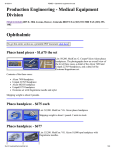
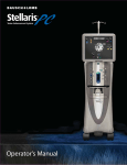
12
CAPSULE REGULAR
CAPSULE HIGH
GLAUKOMA IDK
GLAUKOMA STT
Output power [W]
10
8
6
4
2
0
0
100
200
300
400
500
600
700
800
900
1000
Load resistance [Ohm]
Diathermy
9
DIA 5%
DIA 25%
DIA 50%
DIA 75%
DIA 100%
8
Output power [W]
7
6
5
4
3
2
1
0
0
100
200
300
400
500
600
700
800
900
1000
Load resistance [Ohm]
DIA 50 Ohm and 100 Ohm
9
8
7
Output [W]
Air 6.5…10 bar, max. 40 l/min,
NIST EN-739 connection
Mains voltage
100…240 VAC
Mains frequency
50…60 Hz
Power consumption
270 VA (590 VA with Vitrex)
Fuses
3.15 AT, high breaking capacity
Operating mode
continuous
Application parts
non-earthed, type BF (IEC 601),
Exception: Phaco type B
Protection class
I
CE classification
2B
HF output power
Phaco: 26....30kHz 28kHz nom.
46W ± 8 W (100%/1000Ω)
Diathermy
500 kHz 0-8 watt, nom. at 50 Ohm
Capsulotomy
automatic energy
500kHz control, regular 6.5W
high 9.9W, eff. at 50Ω
IDK 5.5W
STT 6W at 50 Ω
Vitrectomy
VIT A, B: 30 – 1200/min
VIP PN: 1500/min
optionally 3000/min
Max. HF output voltage Diathermy: 60Vss (47Ω/100%)
HF CUT: 270Vss (47Ω)
Phaco: 550Vss (1100Ω/100%)
Vitrectomy: 200Vss (at instrument
input)
Aspiration flow
0-50 ml/min ±25%
Vacuum
0-600 mmHG ±10%
0-80kPa ±10%
Noise level
<70 dB (A)
Dimensions
380 x 150 x 340 mm (W/H/D)
Weight
Unit 14.8 kg
Pedal 4.8 kg
Transport and storage Temperature: -20°C…+55°C
Conditions
Air pressure: 500hPh…1060hPa
Relative air humidity: 10%…95%,
non condensing
Operating conditions
Temperature:10°C...40°C
Air pressure: 700...1060hPa
Relative air humidity: 20%....80%
non condensing
HF-CUT
Supply pressure*
6
5
4
3
2
DIA 50 Ohm
DIA 100 Ohm
1
0
0
10
20
30
40
50
60
70
80
Set value [%]
20
90
100
16
Overview of messages, warnings and error
messages
Contact service (The pedal is not properly set)
The unit cannot be used.
Graphic Display
Error 4
Call service (ParaProg display is defective)
Select surgeon!
Asks you to select the correct surgeon number
Pressure too low
The pressure at the compressed air connection is too low.
Venturi and VIT PN cannot be operated properly. Check
mains pressure and replace venturi nozzle filter if necessary
(Service Manual)
Connect handpiece!
The phaco handpiece is not connected, or not connected
properly.
Program Failure
Error 8
Contact service. The unit cannot be used.
NV Ram failure
Error 9
Contact service. The unit cannot be used.
Pump Failure
Error 10
Contact service (Pump doesn't work).
The unit cannot be used.
Overload
Error 11
Loading too high. Wait until the respective switching circuit
has cooled down: the message will disappear.
Defective handpiece!
The handpiece cannot be operated.
See Section 8.3.1
Irr Motor
Error 12
Infusion rod has been knocked.
Wait until the message disappears, then lower the rod.
Test handpiece!
The handpiece has a low output.
See chapter 8.3.1.
Insert cassette!
Insert a cassette, or close the cassette door properly.
Empty cassette!
The cassette is completely full. Empty immediately.
Update Vitrex
Error 13
BASIC has a newer SW then VITREX
Call service
Force Sensor
Error 15
Forcesensor defective.
Call service
No pedal!
The pedal is not connected or not properly connected.
PREOP discontinued!
PREOP was interrupted by pressing pedal with the heel.
Phaco test active
The phaco test is under way and nothing else can be
operated.
Adjust Venturi
Error 16
Impossible venturi sensor calibration values.
Call service.
Adjust Force Sens Error 17
Impossible peristaltic sensor calibration values.
Call service.
Check Venturi
Error 18
Venturi System: Vacuum deviation to high.
Call service
Phaco test OK
The phaco test has been completed successfully.
Please repeat phaco test!
The test was interrupted and must be repeated.
Errors 5, 6 and 7 do not appear for this unit
Phaco Test discontiued!
The test was interrupted by pressing pedal with the heel.
System ready!
The self-test has been completed successfully.
Check tip!
The tip is not properly attached.
See Section 8.3.1
Call Service,
Error 1
Contact service (Internal voltages defective)
The unit cannot be used.
Adjust Unit,
Error 2
Contact service. (Pressure measurement incorrect)
The unit cannot be used.
Adjust Pedal
29.05.09
Error 3
VV016011E
21
17
Symbols
18
Use only mains fuses with the specified value
Calibration and maintenance
Provided that the cassettes are replaced regularly in
accordance with the instructions in the packaging, this unit
requires only the following calibration and maintenance:
Yearly calibration:
Adjustment of pressure sensor as instructed in the
service manual.
Application parts type BF
Application parts type B
Yearly maintenance:
Inspect electrical cables (instrument and mains) for signs
of wear and tear, and replace where necessary.
Read user manual!
Dangerous electrical current.
Do not open unit!
19 Disposal
This unit should be disposed of in accordance with local
regulations for the disposal of electronic equipment, or it
should be returned to the manufacturer for disposal.
Footswitch connection
Items designed for single use should be disposed of in
accordance with local regulations for the disposal of
contaminated medical waste.
Earthing pin
Remote control
Marking for installation of IV pole (service only)
The cart with the tray fully stretched out can tip
over if inclined more than 6°! The cart must only
be moved when the tray is fully folded and
stored.
Instruments for repair should be cleaned and sterilised prior
to their return to the service centre.
Color coding of machine packs
For ease of identification the following color codes are used
in addition to identification numbers and product description.
Color codes appear normally on the secondary pack (card
board box) only.
OS3 TwinVac
Phaco accessories included
Vitrectomy accessories included
29.05.09
VV016011E
22
20
OS3 Base Unit, VC830100, Overview
Front, without control panel
Rear
A
B
C
D
E
F
G
H
J
K
L
M1
M2
M3
29.05.09
Phaco handpiece connection
Diathermy/capsulotomy connection
Vitrectomy connection, instrument A
Vitrectomy connection, instrument B
Connection 1 for pneumatically-operated
vitrectomy instrument
Connection 2 for pneumatically-operated
vitrectomy instrument
Cassette rotary switch
ParaProg screen
ParaProg combi-switch
Compressed air connection NIST EN 397
Slot for smart card (see service manual)
Pedal port
Reserve port
Control panel port
N
O
P
Q
R
S
T
U
V
W1
W2
W3
W4
X
Y
VV016011E
Serial interface (see service manual)
Mains connection socket
Fuse holder
Mains switch
Compressed air connection line (see service
manual)
Connection for data lead to the Vitrex module
Earthing pin
Interconnecting cable to Vitrex module
Park socket for interconnecting cable
Position of irrigation hose
Position of connection for infusion bottle
Position of aspiration hose 1
Position of aspiration hose 2
Fixture for insertion of the control panel
Marking for installation of IV pole (service only)
23