Download Quick Installation Guide
Transcript
Quick Installation Guide
5.8GHz AV Sender
Introduction to the AV Sender
AV Sender applies advanced 5.8GHz RF wireless
technology to offer users the ability to link all kinds of
Audio and Video sources to TVs, Monitors, and
Personal Computers without wires or cables. The
AV Sender is easy to completely install within
minutes. This plug-and-play feature helps you to
expand your freedom in your home entertainment.
Applications
z Works as the wireless remote unit for A/V
equipment such as Camcorder or DVD.
z May be used as part of a wireless security
system.
z Can be used as a baby sitter to watch your
baby constantly from anywhere in your home.
z Monitor and record a meeting from another
room.
z Use multiple receivers for broadcasting to
numerous TV sets in other rooms.
Features
z 7 selectable channels help prevent any
interference and allow operation of 7 pairs of
AV Senders simultaneously.
z Easy plug-and-play installation within minutes.
z Works with all kinds of Audio and Video
equipment in your home.
z Penetrates walls, floors and ceilings without
damaging your home.
z Crystal - clear Audio and Video signals.
Using the Remote Control Feature
4. Two AV cables
5. SCART converters (optional)
6. IR Extender Mouse
Installation
Possible A/V sources units: The A/V display units:
VCR
TV
Satellite Receivers
DVD Player
Camcorder
Security Camera
Computer
Cable Box
Cassette Deck
Stereo Receiver
TV
Monitor
Speakers
5.8Ghz Audio/Video Signal
Package Contents
This package contains the following items:
1. Quick Installation Guide
2. One Transmitter (Tx) & One Receiver (Rx)
3. Two power adapters.
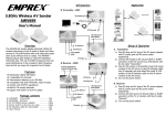
1. Plug the IR Extender Mouse connector
into its special jack at the rear of the AV
Sender Transmitter. (See Photo C)
2. Locate the IR sensor on the A/V source
equipment you wish to control. You can
find the location of the IR sensor by
consulting the user’s manual of the A/V
source equipment.
3. Point the IR Extender Mouse housing in
the general direction of the IR sensors of
the A/V source equipment you wish to
control. Cut a piece of the fastener strip
provided to secure the IR Extender Mouse
in the appropriate location.
4. Position the AV Sender receiver to allow
your remote control signal to strike the IR
window on the front bottom of the
Receiver.
5. To perform the remote control feature,
point the remote control at the front of the
AV Sender Receiver.
Channel switch selection
The channel switch is located at the side of the
transmitter and receiver. (See Photo A.)
Set to receive a specific channel. Both the
transmitter and receiver need to have the channel
switch set to the same channel. If there is
interference on the reception, change both the
transmitter and receiver channel setting to a
different channel.
Photo A:
PROBLEM
No
picture/sound
transmission
Photo D:
channel switch
power switch
Receiver
Transmitter
Photo B:
(Shown above is the antenna direction for application.)
Specification
channel Indicator: CH1 ~ CH7
remote control indicator
Photo C:
(Receiver)
SCART (IN)
Transmitter:
1. Frequency:
2. Channel:
3. Modulation:
Input level:
4. Input port:
5. Antenna:
6. Power supply:
5.725GHz – 5.875GHz
7 selectable channels
FM-FM
Video - 1 Vp-p
Audio - 3 Vp-p
Video - 75 ohms
Audio - 10K ohms
RCA jack
Built in antenna
DC 9V power adapter
Receiver:
1. Frequency:
2. Channel:
3. Output port:
4. Antenna:
5. Power supply:
5.725GHz – 5.875GHz
7 selectable channels
RCA jack
Built in antenna
DC 9V power adapter
Impedance:
Audio R-Audio L-Video power jack
Trouble Shooting
(Transmitter)
IR Extender Mouse jack
SCART (OUT)
If a problem occurs, first refer to this information before
you take the device for repair.
If you are unable to rectify the fault using the information
given here, contact your local dealer or service
specialist.
Under no circumstances should you attempt to repair the
device yourself, as this would invalidate the warranty.
POSSIBLE CAUSE
The transmission
channels for the
transmitter/receiver
do not correspond.
The transmission
distance is too
great.
Connecting cable.
REMEDY
Set the transmission
channel on the
transmitter/receiver
Reduce the distance.
Check the EURO-AV
plug and the cinch
plug.
Switch on the
Transmitter or
transmitter or
receiver not
receiver
switched on.
Wrong direction of Adjust the antenna
patch antenna
to the right position.
See Photo D.
Interference.
Move the transmitter
Poor
or receiver a few
picture/sound
centimeters
quality
Change the
transmission
channel on the
transmitter/receiver
Change channel to
Microwave units
and the use of the find better channel to
receive.
so-called ”blue
tooth function” (W
LAN) on mobile
phones or
notebooks.
Infrared module.
Check the
connection and
position of the
infrared module.
Switch this device
The remote A wireless
off.
control of the transmitter in the
signal source 433MHz range
(e.g. a baby-phone)
does not
is interfering with
respond.
the transmission.
3100554201
Version 1.0



![Installation Guide: AT-TQ2450 [Rev A] (PDF Version)](http://vs1.manualzilla.com/store/data/005654085_1-f326a5d33793ff2ec849a19a13c1dba6-150x150.png)
