1
μC3
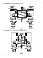
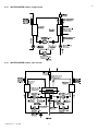
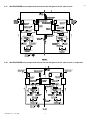
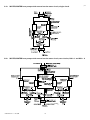
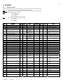
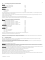
8.4
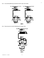
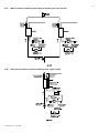
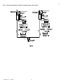
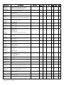
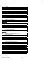
Air-cooled condensing units
8.4.1
Cooling only
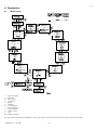
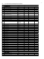
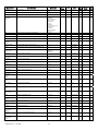
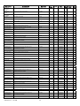
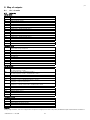
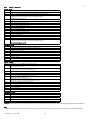
DIGITAL INPUTS
ID 1
Serious alarm / Remote ON/OFF (with digital controls). Serious alarm (with analogue control)
ID 2
Compressor 1 control (with digital controls) Not used (with analogue control)
ID 3
Compressor 2 control (with digital controls) Remote ON/OFF (with analogue control)
ID 4
Compressor 3 control (with tandem circuits and with digital controls)
Compressor 3 and 4 control (with trio circuits and with digital controls)
Not used (with analogue control)
ID 5
Low pressure switch circuit 1
ID 6
High pressure switch circuit 1
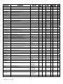
ID 7
Compressor 1 thermal overload circuit 1
ID 8
Compressor 2 thermal overload circuit 1
ID 9
Condenser fan 1 thermal overload circuit 1
ID10
Low pressure switch circuit 2
ID11
High pressure switch circuit 2
ID12
Compressor 1 thermal overload circuit 2
ID13
Compressor 2 thermal overload circuit 2
ID14
Condenser fan 1 thermal overload circuit 2
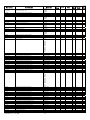
ID15
ID16
Compressor 3 thermal overload circuit 1 / Condenser fan 2 thermal overload circuit 1
ID17
Compressor 3 thermal overload circuit 2 /Condenser fan 2 thermal overload circuit 2
ID18
Compressor 4 control (with tandem circuits and with digital controls)
Compressor 5 and 6 control (with trio circuits and with digital controls)
Not used (with analogue control)
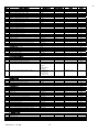
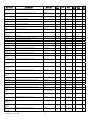
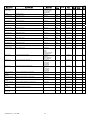
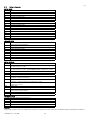
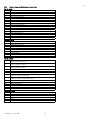
ANALOGUE INPUTS
B1
Condensing temperature circuit 1/Evaporation pressure circuit 1
B2
Condensing temperature circuit 2 /Evaporation pressure circuit 2
B3
Condensing pressure circuit 1
B4
Condensing pressure circuit 2
B5
B6
B7
Outside temperature
B8
Remote set point
B9
B10
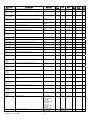
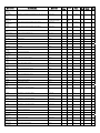
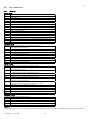
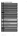
DIGITAL OUTPUTS
NO1
Compressor 1 circuit 1 / Winding A compressor 1 circuit 1
NO2
Compressor 2 circuit 1 / Winding B compressor 1 circuit 1 /
Part load compressor 1 circuit 1
NO3
Liquid solenoid circuit 1 / Compressor 3 circuit 1/
Part load compressor 1 circuit 1 / Condenser fan 2 circuit 1
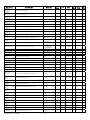
NO 4
Condenser fan 1 circuit 1
NO 5
NO 6
Compressor 1 circuit 2 / Winding A compressor 1 circuit 2
NO 7
Compressor 2 circuit 2 / Winding B compressor 1 circuit 2 /
Compressor 1 capacity control circuit 2
NO 8
Liquid solenoid circuit 2 / Compressor 3 circuit 2/
Compressor 1 capacity control circuit 2 / Condenser fan 2 circuit 2
NO 9
Condenser fan 1 circuit 2 / Condenser fan 2 circuit 1
NO10
General alarm
NO11
NO12
NO13
NO14
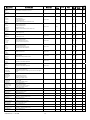
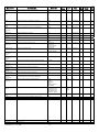
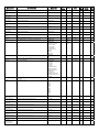
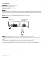
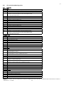
ANALOGUE OUTPUTS
Y1
0 to 10 V condenser fan inverter circuit 1
Y2
0 to 10 V condenser fan inverter circuit 2
Y3
PWM condenser fan inverter circuit 1
Y4
PWM condenser fan inverter circuit 2
Y5
Y6
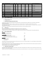
Important:
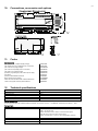
If using a single condenser, with 2 fans configured and 3 compressors configured, in the event of step control, the dedicated outputs will be number 4 and number 9.
+030220431 rel 1.1 10/10/06
69