1
Dear customer,
Let us congratulate you on having purchased the SmartGate system. This new
product has been developed and manufactured to provide the maximum utility value,
quality and reliability. We hope you will be fully satisfied with this GSM gateway for a
long time. Therefore, use your SmartGate for purposes it has been designed and
manufactured for, in accordance herewith.
The manufacturer reserves the right to modify the product in order to improve its
qualities.
Safety Precautions
Do not switch on SmartGate in the vicinity of medical apparatuses to avoid
interference. The minimum distance of the antenna and pacemakers should be
0,5 m.
Do not switch on SmartGate aboard of a plane.
Do not switch on SmartGate near petrol stations, chemical facilities or sites
where explosives are used.
Any mobile telephone use prohibition based on RF energy radiation applies to
SmartGate too.
SmartGate may disturb the function of TV sets, radio sets and PCs.
Warning! SmartGate contains components that can be swallowed by small
children (SIM card, antenna, etc.).
The voltage value mentioned on the power adapter may not be exceeded. If you
connect SmartGate to another power supply, make sure that the voltage value is
in the acceptable range.
When your SmartGate comes to the end of its operational life, dispose of it in
accordance with applicable regulations.
User Manual Versions
Version
1.00
Amendments to Earlier Versions
· The User Manual applies to SmartGate FW Version 1.00A.
Upgrade
The manufacturer continuously meets customer requirements by improving the
firmware. For the latest SmartGate processor firmware, programming tool and User
Manual see www.2n.cz. For a detailed description of the SmartGate firmware upgrade
refer to the section devoted to the PC programming tool.
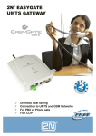
Packing List
SmartGate delivery contains the following items:
Item
SmartGate
Number of
Pieces
1 pc
Antenna for direct connection
1 pc 1)
Magnetic Antenna with coax cable
1 pc 1)
Supply adapter
1 pc
Telephone cable
2 pc
PC-connection serial cable
1 pc
SMS sending input connector
1 pc
Dowels
2 pcs
Screws
2 pc
CD-ROM with User Manual and software
1 pc 2)
Quick Installation Guide + mounting pattern
1 pc
Warranty certificate
1 pc
Notes:
1) The delivery includes an antenna to be connected directly to the SmartGate
SMA connector. An antenna with a cable should be used when GSM signal is
poor or in case of interference with other devices.
2) Enclosed software:
· SmartGate PCManager for parameters programming.
· SmartGate SMSgateway for easy SMS sending and receiving.
· SmartGate Driver for PC.
· User Manual in pdf format.
· Lists of AT Commands for SIEMENS GSM modules.
CONTENTS
1.
SMARTGATE PURPOSE .................................................................................................... 1
1.1.
1.2.
2.
INSTALLATION ................................................................................................................... 2
2.1.
2.2.
2.3.
2.4.
2.5.
2.6.
2.7.
2.8.
3.
DIALTHRU GATEWAY ................................................................................................................ 10
GATEWAY FOR EXTENSION LINE OF PBX.................................................................................... 12
GATEWAY FOR TRUNK LINE OF PBX........................................................................................... 13
SMS SENDING INPUT....................................................................................................... 14
COM – SERIAL INTERFACE............................................................................................. 15
7.1.
7.2.
7.3.
7.4.
7.5.
7.6.
7.7.
8.
PIN ENTERING BY PCMANAGER ................................................................................................. 8
PIN ENTERING VIA TELEPHONE LINE ........................................................................................... 8
AUTOMATIC PIN ENTERING......................................................................................................... 9
VOICE FUNCTION ............................................................................................................. 10
5.1.
5.2.
5.3.
6.
7.
INDICATION LEDS....................................................................................................................... 6
TELEPHONE LINE TONES ............................................................................................................ 7
SIM CARD PIN PROTECTION ............................................................................................ 8
4.1.
4.2.
4.3.
5.
PROPER LOCATION .................................................................................................................... 2
EXTERNAL ANTENNA CONNECTION .............................................................................................. 3
SIM CARD INSTALLATION ............................................................................................................ 3
CONNECTOR DESCRIPTION ......................................................................................................... 4
TELEPHONE LINES CONNECTION ................................................................................................. 4
POWER SUPPLY CONNECTION .................................................................................................... 5
SMS SENDING INPUT CONNECTION ............................................................................................ 5
PC CONNECTION ....................................................................................................................... 5
SMARTGATE STATUS INDICATION.................................................................................. 6
3.1.
3.2.
4.
BASIC FUNCTIONS ...................................................................................................................... 1
ADVANTAGES OF SMARTGATE USE ............................................................................................. 1
PROGRAMMING, MONITORING ................................................................................................... 15
CSD PC-PC DATA TRANSMISSION ........................................................................................... 15
FAX TRANSMISSION - PC-FAX ................................................................................................. 16
CSD OR HIGH-SPEED GPRS DATA CONNECTION TO INTERNET.................................................. 16
SMS SENDING AND RECEIVING ................................................................................................. 16
COMBINATION OF COM TRAFFIC WITH VOICE CALLS .................................................................. 17
LIST OF SUPPORTED AT COMMANDS ......................................................................................... 17
SMARTGATE PARAMETER PROGRAMMING ................................................................ 18
8.1.
8.2.
PC BASED PROGRAMMING ........................................................................................................ 18
PARAMETER TABLES ................................................................................................................ 21
9. TROUBLESHOOTING ....................................................................................................... 39
10. LIST OF ABBREVIATIONS ............................................................................................... 40
11. TECHNICAL PARAMETERS ............................................................................................. 41
1. SmartGate purpose
1.1. Basic Functions
·
·
·
The primary purpose of SmartGate is to transmit voice between GSM network and
attached phone terminals. You can connect terminal with FXO interface (trunk line
of PBX, phone set, answering machine etc.) to FXS interface on SmartGate
(connector with phone icon) and terminal with FXS interface (extension line of PBX)
to FXO interface on SmartGate (connector with crossed out phone icon).
You can establish data connections (GPRS, CSD), fax connections (PC-FAX only)
and send/receive SMS using SmartGate in combination with a PC and appropriate
software.
You can send an SMS to a pre-programmed number using the SMS sending input.
1.2. Advantages of SmartGate Use
·
·
·
·
·
·
·
·
·
·
·
Call cost cutting – the calls are routed to GSM or analog network according to their
number prefix. Route all GSM calls from PBX to SmartGate to save a lot on PSTN –
GSM calls.
Easy installation – you can easy program SmartGate as you need with enclosed SW.
You get all you need in the delivery – your SmartGate delivery contains all you need
to operate the system (the power supply adapter, telephone cables, PC serial cable,
SMS input connector, CD-ROM with software).
Solution for sites without telephone lines – such as mountain chalets, exhibitions,
conferences, etc.
DialThru technology – all your calls will be routed most cost-effective way.
Follow-me function – you newer miss an incoming call from analog network.
Incoming call will ring on connected phone and on your mobile phone too.
CLIP - SmartGate is equipped with the FSK-based CLIP feature, so if a terminal
capable of receiving the CLIP is used you know the caller‘s number.
Quick data connection – SmartGate transmits data using the high-speed GPRS
connection (GPRS class 10, max. 85.6 kbps).
SMS sending input – simply send an SMS to a pre-programmed number by closing
the contact. Recommended for easy supervision, simple securing, etc.
Radiation hazard minimization – you are not exposed to a direct effect of the
antenna RF electromagnetic field while telephoning as opposed to mobile telephones.
Full GSM coverage - SmartGate is available as tri-band for European markets
(900, 1800 and 1900MHz), and as tri-band for the American market (850, 1800 and
1900MHz).
1
2. Installation
2.1. Proper Location
·
·
·
·
·
·
·
·
·
SmartGate is designed for vertical mounting on suspension holes (use the mounting
pattern). This position is the best for signal reception because a vertical antenna is
used. SmartGate can be operated in the horizontal position too where the GSM
signal is good or with antenna connected on coax cable.
Install SmartGate with respect to the GSM signal strength – check the signal strength
using the PCManager.
Place SmartGate out of range of sensitive devices and human bodies for
electromagnetic interference reasons.
SmartGate can disturb other telecommunication systems. Place phone lines and
connected terminals and PBX’s faraway from antenna.
For the allowed range of operating temperatures refer to the “Technical
Parameters”.
It is impossible to operate SmartGate on sites exposed to direct solar radiation or
near heat sources.
SmartGate is designed for indoor use. It may not be exposed to rain, flowing water,
condensed moisture, fog, etc.
SmartGate may not be exposed to aggressive gas, acid vapours, solvents, etc.
SmartGate is not designed for environments with high vibrations such as means of
transport, machine rooms, etc.
2
2.2. External Antenna Connection
Screw the antenna enclosed into the SMA antenna connector. Tighten the antenna
connector gently with your hand - never use spanner!
The antenna for direct connection has a sufficient gain for trouble-free operation in
normal conditions. If the GSM signal is poor, in case of voice disturbance, or if you want
to place your antenna separately from SmartGate, you can use an antenna with an
SMA-connector terminated coax cable. The antenna should be mounted vertically.
For antenna and cable parameters see the “Technical Parameters“.
2.3. SIM Card Installation
Open the SIM card holder on SmartGate’s backside, insert the SIM card and close it
properly. Select the required GSM provider and SIM card services, such as call
forwarding, call barring, preferred networks, SMS service centre, etc. in your mobile
phone before inserting your SIM card in SmartGate.
3
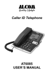
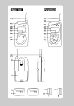
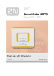
2.4. Connector description
1
2
3
4
1
SMS sending input
2
Telephone line – interface FXO
RJ 11, 6/2
3
Telephone line – interface FXS
RJ 11, 6/2
4
Power supply connector
DC Jack 5,5/2,1mm
5
RS232C serial line
D-Sub 9 pins
5
2.5. Telephone Lines Connection
2.5.1. DialThru gateway – basic connection
Phone set is normally connected to extension line of PBX. Wire up SmartGate
between phone set and PBX. Link extension line of PBX to FXO interface and phone
set to FXS interface on SmartGate.
2.5.2. Gateway for extension line of PBX
Link free extension line of your PBX to FXO interface on SmartGate. FXS interface
remains unconnected.
2.5.3. Gateway for trunk line of PBX
Link free trunk line of your PBX to FXS interface on SmartGate. Program PBX to
route all GSM calls to SmartGate. Incoming calls from GSM network will be routed to
PBX.
You can connect a standard telephone, answering machine or any other FXO-interface
terminal to SmartGate. Outgoing calls from phone will be routed to GSM network, incoming
calls from GSM will ring on the phone.
SmartGate is equipped with the FSK-based CLIP and so it is advantageous to connect a
terminal that is able to display or process the CLI. You must activate the function on
SmartGate.
2.5.4. Gateway for both, trunk and extension, lines of PBX
SmartGate is very flexible thanks to his three routing tables. You can connect trunk and
extension lines of one PBX to proper connectors on SmartGate. You can program the
complex as follows: outgoing calls from PBX will be routed through trunk line to GSM
network. Incoming calls from GSM will be routed to extension line of PBX. This
configuration is suitable for PBX’s with no capability of dial-in on trunk lines.
4
2.6. Power Supply Connection
SmartGate is powered with 10-16V DC. Where a source other than the included power
supply adapter is used, the voltage range and polarity shown on the SmartGate power
supply connector have to be maintained. For backup power supply you can use
EnergyBank – backup source with accumulators.
Do not power on the supply until the antenna is connected to SmartGate to avoid the
GSM module damage.
2.7. SMS Sending Input Connection
You have got a special connector for easy connection to SmartGate. The connector
is equipped with screwing clamps to connect wires from a switching contact (device to
be monitored). The other connector end can be connected to the respective SmartGate
panel connector.
The input is designed for the contact of relay connected between the input pins. The
input is activated by contact closing (pin interconnection).
A transistor switch or logic signal can be used too. The pin near the telephone line
connector is connected to GND of the device the second one is active. Please, respect
the loop current polarity. There is over-voltage protection up to +12V DC there.
2.8. PC Connection
You have got a serial cable for PC connection. It is a modem cable where all of the 9
pins are 1:1 interconnected – in case you want to use another cable.
If you use a longer cable, make sure it works properly. There may occur errors at higher
transmission rates.
5
3. SmartGate Status Indication
3.1. Indication LEDs
Name
Meaning
Power supply
· Light = SmartGate is powered.
· Flashes once in 2s = HW error, contact the manufacturer.
·
·
·
·
GSM network
·
·
Light = registered into GSM network
Flashes once in 1s = not registered, SIM card inserted
Flashes once in 3s = not registered, SIM card not inserted
Flashes 4 times quickly = enter your PIN
Flashes 8 times quickly = enter your PUK
Flashes quickly continuously = all functions are blocked.
Your SIM doesn’t correspond to the GSM operator lock
· No light = standby
Telephone line
Orange for FXS interface:
· Flashes quickly = line off-hook or ringing
· Light = call FXS – GSM
· Flashes once in 3s = data connection in progress
Green for FXO interface:
· Flashes quickly = line off-hook or ringing
· Light = call FXO – GSM
Alternately orange and green:
· Quickly = ringing from FXO is connected to FXS interface
· Slowly = call FXS – FXO
6
3.2. Telephone Line Tones
3.2.1. Status Tones
The GSM gateway sends tones to the telephone line to indicate the line status. The
tone frequency is 425 Hz in initial setting. Frequency is programmable; it is possible to set
up double frequency tones.
Dial tone: Continuous tone, or
(morse A) according to setting
· SmartGate is ready to receive dialing.
Ringing tone:
· The called subscriber's telephone is ringing.
· The GSM network or connected PBX transmits this tone.
Busy tone:
, programmable cadency
· In case of call routing to GSM network SmartGate generate busy tone in any of
the following cases:
§
The SIM card has not been installed.
§
SmartGate is not registered to GSM network.
§
SmartGate is registered into a foreign network but roaming is disabled.
§
The called subscriber line is busy.
§
The called subscriber hangs up (disconnection).
§
The called number has too many digits (more than 30).
§
The called number is barred.
· In case of call routing to SmartGate’s FXO interface SmartGate generate busy
tone in any of the following cases:
§
Line is not connected. There is no current on the line.
§
The called number has too many digits (more than 30).
§
The called number is barred.
§
If the called subscriber line is busy or called subscriber hangs up, busy tone
is generated by PBX.
Dialing end signaling:
· Dialing reception has been terminated. Connection is being established.
PIN tone:
· Enter the PIN code.
· This tone is transmitted upon power up if the PIN has to be entered manually.
PUK tone:
· Enter the PUK code.
· This tone is transmitted upon repeated wrong PIN entering attempts. SIM card is
blocked.
7
4. SIM Card PIN protection
If a SIM card is PIN-protected and the PIN is not programmed in SmartGate, GSM
LED indicates the state and the PIN tone is transmitted on telephone line.
4.1. PIN Entering by PCManager
Like other parameters, the PIN code can be entered using a PC programming tool.
The PIN will be entered automatically upon every SmartGate power up.
4.2. PIN Entering via Telephone Line
PIN entering via a telephone line connected to FXS interface:
1. Hook off the phone, you can hear the PIN tone.
2. Enter the PIN using the DTMF. You can cancel the wrong PIN by entering of a
, or you can hang up before sending a
.
3. To confirm enter a
.
4. If you hear the busy tone in a while (a few seconds), you have entered the PIN
correctly. Hang up and wait for registering to the GSM network.
5. If you hear the PIN tone again in a while, you have entered a wrong PIN. Reenter the PIN correctly.
6. If you hear the PUK tone in a while, you have entered a wrong PIN and the
SIM card is blocked. Use the mobile phone to unblock the SIM card.
PIN entering via a telephone line connected to FXO interface if SmartGate is used as
gateway for extension line of PBX:
1. Dial the SmartGate’s extension number on your PBX. SmartGate detects
ringing and after off hook generates the PIN tone.
2. Enter the PIN using the DTMF. You can cancel the wrong PIN by entering of a
, or you can hang up before sending a
.
3. To confirm enter a
.
4. If SmartGate after a while (a few seconds) hangs up, you have entered the
PIN correctly.
5. If you hear the PIN tone again in a while, you have entered a wrong PIN. Reenter the PIN correctly.
6. If you hear the PUK tone in a while, you have entered a wrong PIN and the
SIM card is blocked. Use the mobile phone to unblock the SIM card.
A correctly entered PIN is stored in SmartGate’s memory as if you had programmed
it using the PCManager. The PIN will be entered automatically upon every SmartGate
power up.
8
4.3. Automatic PIN Entering
You need not enter the PIN upon power up if it is stored in SmartGate – it is entered
automatically. This function is useful in case of power failure; SmartGate is operable in
a short time after power recovery without any intervention by the operating staff.
Caution! One PIN entering option is exhausted by the attempt to enter the PIN
automatically upon SIM card or PIN change. If wrong, the automatically entered PIN is
cleared from the internal memory to avoid another false attempt upon next power on.
There are still two manual PIN-entering attempts after such unsuccessful automatic
entering. To prevent the unsuccessful automatic PIN entering, delete or program
properly the SmartGate PIN using the PCManager in the case of SIM card change.
9
5. Voice function
Outgoing and incoming call establishing procedures is for illustration described for
analog phone connected to FXS interface and extension line of PBX connected to FXO
interface on SmartGate. In case of other equipment connection, please check
SmartGate’s function by connecting a phone.
Suppose that a SIM card has been inserted, the PIN code entered or not required,
the antenna connected and SmartGate registered to GSM network – the GSM network
LED is permanently on and you can hear the dial tone upon line off-hook.
5.1. DialThru gateway
Extension line of PBX is connected to FXO interface and phone is connected to FXS
interface on SmartGate.
5.1.1. Outgoing call on FXS interface
1. Hook off the telephone, you can hear the dial tone and the Line LED starts flashing.
2. Dial the required subscriber number. SmartGate receives tone dialing (DTMF) by
default. If your telephone transmits pulse dialing only, program SmartGate to
receive pulse dialing. The delay between dialed digits may not exceed 5 s
(programmable parameter). The number is evaluated as complete after this timeout.
3. A short delay follows the last-dialed digit for SmartGate to await further dialing.
Then, the dialing end is signaled and connection is established.
4. Prefix of dialed number is compared with filled rows of FXS routing table. The call is
rejected, routed to GSM network or to FXO interface according to the routing table.
5. If the called subscriber is available, you can hear the ringing tone. If not, you can
hear the busy tone or any of the GSM provider’s messages.
6. When the called subscriber answers the call, a call is established. The Line LED is
permanently on during the call (Orange for calls to GSM. Green-Orange alternate
for FXS-FXO calls).
7. Hang up to terminate the call. The Line LED goes off. If the called subscriber hangs
up first, you can hear the busy tone.
5.1.2. Incoming call from GSM network
1. The CLI is compared with filled rows of GSM routing table. The call is rejected,
routed to FXS interface – connected phone, or to FXO interface according to the
routing table. Routing to FXO interface isn’t usually used in case of DialThru
gateway.
2. Ringing on FXS interface signals incoming call. The Line LED flashes during
ringing. If programmed so, SmartGate transmits the CLIP by FSK between the first
and second rings. Advanced telephone sets are able to display the CLI.
3. Hook off the phone to establish the call. The Line LED is permanently on during the
call.
4. Hang up to terminate the call. The Line LED goes off. If the called subscriber hangs
up first, you can hear the busy tone.
10
5.1.3. Incoming call on FXO interface
1. SmartGate detects a ringing signal and immediately interconnects it to FXS
interface – the phone starts to ring.
2. The CLIP transmitting must provide connected PBX.
3. If you hook off the phone the call is established.
5.1.4. Automatic Call ("BabyCall")
If the BabyCall function is enabled on FXS interface, a pre-programmed timeout is
counted down after off-hook. If you don’t start dialing within this timeout, SmartGate
signals dialing end and starts to establish a call to the pre-programmed number using
GSM network automatically – from now SmartGate behaves as if a standard outgoing
call to GSM had been established. Any dialing during the BabyCall timeout cancels this
function and a standard outgoing call can be made.
5.1.5. Follow-me
Follow-me function takes place during ringing on FXS interface if SmartGate is
programmed as DialThru gateway.
Fill in telephone number for Follow-me function and number of rings to Follow-me
function start.
1. SmartGate detects a ringing signal and immediately interconnects it to FXS
interface – the phone starts to ring.
2. If there is no call connection before the pre-programmed number of rings,
SmartGate simultaneously establishes call to GSM network. Some timeout take
place between GSM call establishing start and ringing of mobile phone.
3. As long as SmartGate detects ringing on FXO interface, connected analog and
GSM phones ring.
4. You can receive the call on analog line as well as on your mobile phone.
If you want repeatedly temporarily disable and afterwards enable the Follow-me
function, fill in Password for Follow-me activation/disabling. If password is filled in:
1. Hook off the phone.
2. For temporarily disabling the function dial the password and confirm by
For activation the function dial the password and confirm by
3. Hang up.
.
5.1.6. Tariff pulses 16 or 12 kHz
SmartGate has tariff pulse transmitter on FXS interface. You can use tariff pulses for
outgoing call pricing. SmartGate offer pseudotariff only – tariff metering doesn’t
correspond to real price of call, tariff pulses are transmitted according to programmed
parameters and call duration. You must program specific parameters in FXS routing
table to set tariff metering for different prefixes of dialed numbers. Tariff metering is
transmitted only during calls to GSM network. Connected PBX must provide the tariff
metering during calls to FXO interface.
You can also program SmartGate to transmit tariff pulses as call connect/disconnect
signaling if your PBX cannot receive telephone line polarity reversal signaling.
11
5.2. Gateway for extension line of PBX
Extension line of PBX is connected to FXO interface on SmartGate. FXS interface
remains unconnected.
You have to program parameter “FXO call route to” for proper function on FXO interface.
You can fill in some rows in FXO routing table to reject given calls, for automatic call routing
etc.
Fill in GSM routing table to route an incoming GSM calls to FXO interface.
It is necessary to set up conditions for call-disconnect detection from PBX. If SmartGate
detects busy tone or continuous tone from PBX, it disconnects the established GSM call.
5.2.1. Outgoing call on FXO interface
1. SmartGate detects a ringing signal from PBX and, if it is possible to establish GSM
call, it hooks off the line after preprogrammed number of rings. SmartGate transmits
dial tone and green LED for line starts flashing.
2. Dial the GSM subscriber number using DTMF. The delay between dialed digits may
not exceed 5 s (programmable parameter). The number is evaluated as complete after
this timeout.
3. A short delay follows the last-dialed digit for SmartGate to await further dialing.
Then, the dialing end is signaled and connection is established.
4. Prefix of dialed number is compared with filled rows of FXO routing table. The call is
rejected or routed to GSM network according to the routing table.
5. If the called subscriber is available, you can hear the ringing tone. If not, SmartGate
hangs up.
6. When the called subscriber answers the call, a call is established. The green Line
LED is permanently on during the call.
7. Hang up to terminate the call. PBX sends busy tone to SmartGate’s subscriber line,
SmartGate detects it and disconnects the GSM call.
5.2.2. Incoming call from GSM network
1. The CLI is compared with filled rows of GSM routing table. The call is rejected, or
routed to FXO interface – extension line of PBX according to the routing table.
2. SmartGate hooks off the line. If there is filled in the “Dial in” parameter for given CLI,
SmartGate dials it using DTMF.
3. The GSM subscriber hears the ringing tone from PBX if the automatic dial in
function was applied, if not he hears dial tone from PBX and he can dial required
extension himself.
4. The call termination is the same as in case of outgoing call.
12
5.3. Gateway for trunk line of PBX
Outgoing and incoming call establishing procedures is for illustration described for
analog phone connected to FXS interface. The rules for call establishing in case of trunk
line connection are the same, you have to program your PBX to route GSM calls to
SmartGate. We strongly recommend to check SmartGate’s function by connecting a
phone in case of interconnection with PBX trunk line.
5.3.1. Outgoing call on FXS interface
1. Hook off the telephone, you can hear the dial tone and the orange Line LED starts
flashing.
2. Dial the required GSM subscriber number. SmartGate receives tone dialing (DTMF)
by default. If your telephone transmits pulse dialing only, program SmartGate to
receive pulse dialing. The delay between dialed digits may not exceed 5 s
(programmable parameter). The number is evaluated as complete after this timeout.
3. A short delay follows the last-dialed digit for SmartGate to await further dialing.
Then, the dialing end is signaled and connection is established.
4. Prefix of dialed number is compared with filled rows of FXS routing table. The call is
rejected, or routed to GSM network according to the routing table.
5. If the called subscriber is available, you can hear the ringing tone. If not, you can
hear the busy tone or any of the GSM provider’s messages.
6. When the called subscriber answers the call, a call is established. The orange Line
LED is permanently on during the call.
7. Hang up to terminate the call. The Line LED goes off. If the called subscriber hangs
up first, you can hear the busy tone.
5.3.2. Incoming call from GSM network
1. The CLI is compared with filled rows of GSM routing table. The call is rejected, or
routed to FXS interface – connected phone according to the routing table.
2. Ringing on FXS interface signals incoming call. The orange Line LED flashes during
ringing. If programmed so, SmartGate transmits the CLIP by FSK between the first
and second rings. Advanced telephone sets are able to display the CLI.
3. Hook off the phone to establish the call. The Line LED is permanently on during the
call.
4. Hang up to terminate the call. The Line LED goes off. If the called subscriber hangs
up first, you can hear the busy tone.
13
6. SMS Sending Input
This universal input is intended especially for reporting alarm or error statuses of any
equipment provided with the appropriate contact (a relay contact, e.g.).
By activating this input (electric input pin interconnection) you send one SMS to one
pre-programmed telephone number.
Caution! Do not use in life-supporting or property-protection applications because of
the character of SMS service and SmartGate equipment. The manufacturer shall not be
liable for health and property damage incurred as a result of SMS sending failure.
14
7. COM – Serial Interface
The complete serial interface RS-232C on a 9-pin connector is identical with any
external modem.
The transmission rate ranges from 1200 to 115200 bps (SmartGate supports
autobauding, i.e. responds to an AT command at a rate identical with the AT command
transmission rate, and retains set on this rate). The transmission setup must be 8 bits,
no parity and one STOP bit (8N1).
SmartGate’s central processor uses the same interface for establishing calls and so it
must have the possibility to block an external serial interface-all PC SW must provide
transmission hardware flow control (HW handshaking).
COM can be used for:
· Programming and monitoring;
· CSD PC-PC data transmission;
· PC-FAX-transmission of fax messages from your PC;
· CSD or high-speed GPRS connection to the Internet;
· SMS sending and receiving.
7.1. Programming, Monitoring
Install the SmartGate PCManager software available on the included CD-ROM into
your PC.
The program is designed for SmartGate parameters programming. It can read
configuration data from the memory and store them in SmartGate. Moreover, all
parameters can be saved in your PC file for backup or saving into another SmartGate
system.
The SmartGate PCManager contains an easy monitoring tool too. With this tool you
can identify the GSM provider’s name, signal strength, GSM module, SIM card, and so
on during SmartGate operation.
7.2. CSD PC-PC Data Transmission
The CSD mode provides data transmission in the GSM network at the maximum
transmission rate of 14400 bps. It works like a classic connection of two modems (AT
commands ATD, ATH, ATA, etc.). Connection can be made with another GSM modem
or a PSTN modem.
Caution! Data calls and fax calls from the PSTN come as voice calls (the telephone
line on SmartGate rings) because an analog network is unable to distinguish a
modem/fax call. Therefore, it is necessary to have a special telephone number for
incoming data and fax calls on the SIM card different from voice call numbers (Multinumbering scheme). The GSM network identifies a call incoming to this number as a
data/fax call and lets the COM serial interface ring.
15
7.3. FAX Transmission - PC-FAX
SmartGate allows fax transmissions from your PC. However, do not confuse the PCFax service with a standard fax service – no fax machine can be connected to the
telephone line! But the PC-Fax can establish connection with a standard fax machine
and transmit documents.
To enable the PC-Fax service, install the faxmodem driver from the SmartGate CDROM first. Further you need the PC-Fax software, which is not included. In general, any
program designed for SIEMENS data modules (SIEMENS MC45/46 or MC55/56) can
work with SmartGate. The WinFax program from Symantec has been successfully
tested for this purpose, you can use the fax service included in Windows XP as well.
7.4. CSD or High-Speed GPRS Data Connection to Internet
To connect to the Internet, install the faxmodem driver from the SmartGate CD-ROM
first. Another possibility is to use the GSM provider’s installation wizard in case it
supports the SIEMENS GSM module installed in SmartGate (SIEMENS MC45/46 or
MC55/56).
The installation wizard usually configures the telephone connection of the network
too. If you use manual installation, you have set it properly. Ask you GSM provider for
Internet connection instructions because they can be different for each provider
(especially the telephone number to be dialed, DNS, etc.). It is necessary, for example,
to set the APN in modem extra settings in the GPRS mode:
Example: at+cgdcont=1,"IP","internet.t-mobile.cz"
Caution! GSM providers mostly specify the *99# number to be dialed for GPRS
connection in their instructions. SIEMENS GSM modules require the *99***1# format.
7.4.1. CSD or GPRS Data Connection?
The maximum CSD transmission rate is 14400 bps. GSM connection is reserved for
the whole time of connection and calls are charged according to the connection time.
The CSD mode can provide data connection of two PCs.
SmartGate is equipped with GSM modules providing GPRS class 10 (4+2 timeslots),
which means that it is able to transmit data into a PC at the rate of 85600 bps and at
half the rate towards the GSM network. The GPRS cannot be used for connection of
two PCs. It can only provide connection with an APN – e.g. the Internet. Most GSM
providers charge GPRS connections according to the volume of data transmitted or by a
lump sum and so the GPRS is suitable for long-time connection with occasional data
transmissions.
7.5. SMS Sending and Receiving
It is possible to send and receive SMS units using appropriate AT commands. There
are a number of PC programs that are based on this principle. Install SW designed for
SIEMENS GSM modules (SIEMENS mobile telephone SW can also be used). You can
send and receive SMS even during SmartGate voice calls.
16
7.6. Combination of COM Traffic with Voice Calls
As already mentioned, SMS transmission can be made even during telephone calls.
The SMS program is only blocked temporarily during outgoing call to GSM establishing
and incoming call from GSM ringing.
The same applies to PCManager monitoring. A message announcing that SmartGate
is blocked is displayed during voice call establishing.
No voice call to GSM can be made during CSD data transmission and PC-FAX
connection.
Outgoing and incoming calls even to GSM can be made during GPRS connection.
The GPRS connection remains active during the whole call to GSM but no data can be
transmitted (SmartGate is a GPRS terminal of class B). Once the call is terminated,
data transmission is recovered immediately.
7.7. List of Supported AT Commands
There are original files related to SIEMENS GSM modules in the PDF format on the
SmartGate CD-ROM.
Caution! Since the GSM module is primarily used by the SmartGate central
processor for voice calls, use AT commands carefully. You might misconfigure the GSM
module thus making SmartGate inoperative. To solve most of these problems, switch
SmartGate off and on again to make the central processor execute full initialization of
the GSM module.
Do not use particularly:
ATQ1
ATS3=
ATS4=
ATS5=
ATV0
AT&C0
AT+IPR=
AT+CFUN=
AT+CMUT=
AT+CMUX=
AT+CSCS=
AT^SAIC=
AT^SM20=
AT^SMSO=
AT^SNFA=
AT^SNFD=
17
AT^SNFI=
AT^SNFM=
AT^SNFO=
AT^SNFPT=
AT^SNFS=
AT^SNFV=
AT^SNFW=
8. SmartGate Parameter Programming
Most of SmartGate’s parameters have such default values that meet most users’
demands and need not be changed. Usually you have to program routing tables
according to SmartGate usage. Use a PC with the PCManager installed for SmartGate’s
parameter programming.
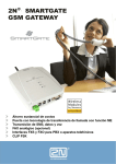
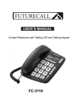
8.1. PC based Programming
For programming, connect SmartGate to a PC with a serial cable and make sure that
the SmartGate PCManager is installed. Programming is intuitive and easy. All items and
parameters are accompanied with texts hints - just point at anything with the mouse
cursor.
SmartGate data uploading and storing, including firmware upgrade, are executed in a
special mode, in which SmartGate waits for about 3s after power up (all LEDs are on). If
instructed so by the PCManager during this timeout, SmartGate remains in this mode as
long as it is necessary. If SmartGate is not reset after the PCManager is terminated,
switch the system off and on again.
Data
handling
Language
selection
Programming
tables
Monitoring
18
8.1.1. Basic Programming Instructions
1. Run the PCManager and select the language for displaying texts on the right-hand
side.
2. Click on the CD-ROM icon for data handling on the left-hand side.
3. Load data from SmartGate – if SmartGate is not in its special programming mode,
you are invited to switch SmartGate off and on again.
4. Click on the programming table icon on the left-hand side.
5. The parameters are arranged according to their functions in the tables. Set all
parameters you want to change. If you point at a parameter with the mouse, help is
displayed.
6. Click on the CD-ROM icon again for handling data.
7. Save data into SmartGate – if SmartGate is not in its special programming mode,
you are invited to switch SmartGate off and on again.
8.1.2. Further Data Handling Options
In addition to the SmartGate memory, settings can be saved in a PC file and
reloaded into the PCManager. This is recommended for backing up of current
configurations or saving the same configuration in another SmartGate unit.
Caution! The table Security includes the PIN code and service password. These
parameters have a special handling. They are not saved in a PC file for security
reasons. If you load a PC file into the PCManager and then into SmartGate, the PIN and
service password should not change unless you change them manually before saving.
Caution! All tables are filled-in with default values after PCManager start. It is
recommended to load data from SmartGate before parameters programming and
saving. If you only save data after PCManager start, all parameters except the PIN and
service password in the SmartGate memory will have default values.
Caution! The PIN and service password can only be modified either manually or by
full initialization.
8.1.3. Upgrade
The manufacturer responds to clients' requirements with periodical firmware
updating. The current SmartGate firmware, PCManager and User Manual are available
on www.2n.cz. The latest firmware version is always included in every new PCManager
installation.
Upgrading procedure:
1. Run the PCManager, select the language for displaying texts on the right-hand side.
2. Click on the CD-ROM icon for data handling on the left-hand side.
3. Click on the upgrade – if SmartGate is not in its special programming mode, you are
invited to switch SmartGate off and on again.
4. If there is more then one file in the PCManager directory, chose one of them. The
upgrade takes place automatically. Do not switch your PC or SmartGate off
during the process of upgrading!
Caution! The PCManager checks the software version in SmartGate and the
upgrade file. If the version in the file is new, everything is all right. An identical or earlier
software version is stored in SmartGate too but the PCManager requires confirmation to
be on the safe side.
19
Caution! With regard to potential SmartGate memory data structure change, the
PCManager and SmartGate are "matched" according to versions. A PCManager
version can be used for SmartGate programming that differs from the SmartGate
version by a letter following the version number (e.g.1.00A). The PCManager itself
identifies this fact and notifies you.
8.1.4. Monitoring
Monitoring is active when SmartGate is in operation and registered to the GSM
network. If SmartGate is not registered to GSM, the COM is blocked and no monitoring
can be made.
This simple informative function helps you identify:
· The GSM module type and IMEI ID;
· The SIM card IMSI ID and selected SMS service centre necessary for SMS
sending;
· The GSM provider's name and signal strength received by SmartGate - this
information helps you find the optimum signal location (the information is updated in
10s intervals);
· The SmartGate line status – standby, outgoing call, incoming call including
telephone number. The COM is locked during dialing and incoming call ringing, so
the PCManager reports COM blocking.
20
8.2. Parameter Tables
All programmable parameters are listed in this section. Each parameter is
accompanied with the unit used, description of SmartGate's behavior, setting options,
setting step and default value (value after initialization). Identical texts are displayed as
help hints in PCManager program.
8.2.1. Telephone interface FXS parameters
Type of dialing
Select the dialing type to be received by SmartGate on the FXS interface.
SmartGate accepts only the selected type of dialing, ignoring the others.
Setting options:
DTMF
-SmartGate receives tone dialing only.
Pulse
-SmartGate receives pulse dialing only
Default setting: DTMF
Timeout for dialing end recognize [s]
Timeout during which SmartGate waits for further digits to be dialed. It starts to
establish connection when this timeout passes.
Setting options: 1-255 s
Setting step:
1s
Default setting: 5 s
Minimal On Hook [ms]
The minimum line current break that SmartGate evaluates as hang-up.
Setting options: 100-25500 ms
Setting step:
100 ms
Default setting: 500 ms
Beep after dialing end
Select a beep to signal the end of dialing (beginning of outgoing call
establishing).
Setting options: YES/NO
Default setting: YES
Dial tone – frequency [Hz]
Setting of frequency/frequencies of dial tone.
Setting options: 1-3400 Hz
Setting step:
1 Hz
Default setting: 425 Hz
21
Dial tone - cadence
This tone is generated after Off-Hook in case SmartGate is ready to accept
dialing.
Setting options:
Continuous -SmartGate generate continuous dial tone
Morse A
-SmartGate generate dial tone with 330/330/660/660 ms
cadence
Default setting: Continuous
Busy tone – frequency [Hz]
Setting of frequency/frequencies of busy tone.
Setting options: 1-3400 Hz
Setting step:
1 Hz
Default setting: 425 Hz
Busy tone - cadence
Busy tone cadence setting.
Setting options:
330/330 ms
-cadence 330 ms tone, 330 ms pause
200/200 ms
-cadence 200 ms tone, 200 ms pause
250/250 ms
-cadence 250 ms tone, 250 ms pause
375/375 ms
-cadence 375 ms tone, 375 ms pause
500/500 ms
-cadence 500 ms tone, 500 ms pause
Default setting: 330/330 ms
Tone after disconnection
If the remote subscriber hangs up first, the SmartGate subscriber can hear the
tone selected here.
Setting options:
Busy
-SmartGate transmits the busy tone upon call end.
Permanent -SmartGate transmits the permanent tone upon call end.
Default setting: Busy tone
Line reversal indication for call in progress
Select call in progress signaling by telephone line polarity reversal on FXS
interface. There is voltage of reversed polarity on the telephone line during the
whole call.
Setting options: YES/NO
Default setting: NO
22
Tariff pulse when call starts/ends
Signaling of call start or end by tariff pulse.
Setting options:
None
-SmartGate doesn't send tariff pulse as signaling of call
start/end.
Call end
-SmartGate sends tariff pulse when call ends.
Call start
-SmartGate sends tariff pulse when call starts.
Call start and end -SmartGate sends tariff pulse when call starts and
ends too.
Default setting: None
Tariff pulse frequency [kHz]
Tariff pulse frequency setting.
Setting options:
16 kHz
-SmartGate transmits 16 kHz tariff pulses
12 kHz
-SmartGate transmits 12 kHz tariff pulses
Default setting: 16 kHz
Ringing signal – frequency [Hz]
Ringing signal frequency setting.
Setting options:
25 / 50 Hz
-SmartGate rings with 50 or 25 Hz on FXS interface
Default setting: 50 Hz
Ringing signal - cadence
Ringing signal cadency setting.
Setting options:
1000/4000 ms
- 1 s ring, 4 s pause
400/200/400/2000 ms
- 400ms ring, 200ms pause, 400ms ring, 2s pause
1500/3500 ms
- 1,5 s ring, 3,5 s pause
2000/4000 ms
- 2 s ring, 4 s pause
Default setting: 1000/4000 ms
CLI transmitting
Set this item to enable/disable identification of a telephone line calling from a
GSM network. The function can be enabled if you have a device on your
telephone line that is capable of receiving FSK according to ETSI standards.
Setting options:
Disable
-SmartGate does not transmit the CLI.
FSK during ringing -SmartGate transmits the FSK-based CLI according to
the ETSI EN 300 659 standard (transmission during ringing).
Default setting: Disable
Replace character + in CLI by
If this parameter is filled, the + character in the international prefix of CLI is
replaced by the defined string. The + character can neither be transmitted by the
FSK protocol nor dialed by the DTMF from a terminal.
Setting options: 0-4 characters (0-9,*,#)
Default setting: blank
23
BabyCall number
A number to be dialed for the automatic call function. If this item is blank, the
function is disabled.
Setting options: 0-20 characters (0-9,*,#,+)
Default setting: blank
BabyCall timeout [s]
Time between line Off-Hook and automatic call beginning (if enabled). During this
timeout SmartGate waits for dialing that cancels the automatic call. You can
make standard call if the BabyCall function is enabled.
Setting options: 0-255 s
Setting step:
1s
Default setting: 0 s
Transmission volume
Volume setting for GSM transmission with a 4 dB step. Setting is common for
both FXS and FXO interfaces.
Default setting: medium volume level
Reception volume
Volume setting for GSM reception with a 4 dB step. Setting is common for both
FXS and FXO interfaces.
Default setting: medium volume level
8.2.2. Telephone interface FXO parameters
Number of rings before Off-Hook
If SmartGate is programmed as FXO gateway, parameter sets the count of rings
before Off-Hook.
Setting options: 1-255
Step:
1
Default setting: 1
Time for dialing start
If SmartGate is programmed as FXO gateway, parameter defines timeout for first
dialing digit. After timeout SmartGate hangs up the line.
Setting options: 1-255 s
Step:
1s
Default setting: 15 s
Timeout for dialing end recognize [s]
If SmartGate is programmed as FXO gateway, parameter defines timeout during
which SmartGate waits for further digits to be dialed. It starts to establish
connection when this timeout passes.
Setting options: 1-255 s
Setting step:
1s
Default setting: 5 s
24
Type of transmitted dialing
Set type of dialing for automatic dial-in from GSM and for dialing during outgoing
call from FXS interface.
Setting options:
DTMF
-SmartGate transmits tone dialing
-for future use
Default setting: DTMF
Minimal On-Hook [ms]
Parameter defines minimal time of line On-Hook between calls. Set the
parameter longer then duration of FLASH on your PBX.
Setting options: 100-25500 ms
Step:
100 ms
Default setting: 1500 ms
Maximal Off-Hook without dialing [s]
Parameter defines maximal time of line Off-Hook before dialing to FXO interface
during outgoing call from FXS interface. Set up shorter time then timeout from
extension line Off-Hook and dialing receiver disconnection on your PBX. In this
case PBX usually changes dial tone to busy tone. If defined timeout passes
before dialing, SmartGate shortly hangs up, after that Off-hooks again and then
dials.
Setting options: 1-255 s
Step:
1s
Default setting: 15 s
Beep after dialing end
If SmartGate is programmed as FXO gateway, parameter enables a beep to
signal the end of dialing (beginning of outgoing call establishing).
Setting options: YES/NO
Default setting: YES
Dial tone – frequency [Hz]
Setting of frequency/frequencies of dial tone.
Setting options: 1-3400 Hz
Setting step:
1 Hz
Default setting: 425 Hz
Dial tone - cadence
This tone is generated after Off-Hook in case SmartGate is ready to accept
dialing.
Setting options:
Continuous -SmartGate generate continuous dial tone
Morse A
-SmartGate generate dial tone with 330/330/660/660 ms
cadence
Default setting: Continuous
25
Busy tone detection
Set number of busy tone periods for detection of call disconnection from your
PBX. The "0" setting disables busy tone detection.
Setting options: 0-255
Step:
1
Default setting: 4
Continuous tone detection [ms]
Set duration of constant frequency continuous tone for detection of call
disconnection from your PBX. The "0" setting disables continuous tone detection.
Setting options: 0-8900 ms
Step:
35 ms
Default setting: 2030 ms
BabyCall number
If SmartGate is programmed as FXO gateway, parameter defines a number to be
dialed for the automatic call function. If this item is blank, the function is disabled.
Setting options: 0-20 characters (0-9,*,#,+)
Default setting: blank
BabyCall timeout [s]
If SmartGate is programmed as FXO gateway, parameter defines time between
line Off-Hook and automatic call beginning (if enabled). During this timeout
SmartGate waits for dialing that cancels the automatic call. You can make
standard call if the BabyCall function is enabled.
Setting options: 0-255 s
Setting step:
1s
Default setting: 0 s
Transmission volume
Volume setting for GSM transmission with a 4 dB step. Setting is common for
both FXS and FXO interfaces.
Default setting: medium volume level
Reception volume
Volume setting for GSM reception with a 4 dB step. Setting is common for both
FXS and FXO interfaces.
Default setting: medium volume level
26
8.2.3. Routing Parameters
All parameters related to the dialed number and call routing are arranged in three
routing tables. Each table pertains to one interface: FXS, FXO and GSM.
FXS routing table
According to the prefix of dialed number on FXS interface you can:
Bar the number to be dialed - the calling subscriber hears the busy tone;
Route the call to GSM network, or to PBX through the FXO interface;
Accelerate connection establishing by knowing the number length for the given
prefix;
· Accelerate connection establishing by allowing to terminate dialing with a #;
· Modify the number to be dialed by removing and/or adding prefix.
· Set tariff metering for the given prefix.
·
·
·
Every table line includes a phone number prefix (of variable length) and other
parameters. The parameters define SmartGate's behavior in case the beginning of the
dialed number matches this prefix on the same table row. The table contains 120 rows
for up to 120 different prefixes.
There may be exceptions to the rule - a number may start with the same digits but
has to be served in a different way. Any table row that starts with the same prefix
followed by one or more digits is considered an exception of the line with shorter prefix.
Remember to complete the "Other prefixes" line for a number whose prefix is not
found in the table.
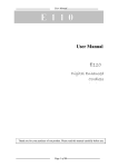
An example in the figure shows how to bar all international calls with the exception of
calls to Slovakia. Calls to Slovakia are routed through FXO interface and the call is
established immediately after 14 digits are dialed. All other calls are enabled and they
27
are routed to GSM network. Their tariff is one impulse every 30 second and you can
accelerate connection establishing by dialing of a # after the dialed number.
Prefix
Dialed number prefix identifying the call type. "Other numbers" line is used for
calls with prefixes that are not included in the table.
Setting options: 0-16 characters (0-9,*,#)
Default setting: blank
Call enable
This parameter allows/bars calls with corresponding prefixes.
Setting options: YES/NO
Default setting: YES
Route to
This parameter defines FXS call routing.
Setting options:
GSM
-the call is routed to GSM network only
FXO
-the call is routed to FXO interface only
GSM, FXO -the call is primary routed to GSM network. In case of GSM
network error, it is routed to FXO interface
FXO, GSM -the call is primary routed to FXO interface. In case of FXO
interface error, it is routed to GSM network
Default setting: GSM
Number length
The parameter defines the expected length of dialed number. It enables to start
dialing into GSM or FXO interface immediately after the last digit is dialed. If the
telephone number to be dialed is shorter, a timeout is respected. The "0" setting
means that the function is disabled.
Setting options: 0, 3-15
Setting step:
1
Default setting: 0
End with #
This parameter enables to establish the call when a # is received. The #
character is removed from the dialed number. If a # should be part of the dialed
number, this function cannot be used for the given prefix.
Setting options: YES/NO
Default setting: NO
Remove
The Remove parameter is used for automatic call routing. A defined count of
digits (prefix) is removed from the number beginning.
Setting options: 0-20
Setting step:
1
Default setting: 0
28
Add
The Add parameter is used for automatic call routing. A defined string (prefix) is
added to the beginning of the number to be dialed.
Setting options: 0-16 characters (0-9,*,#,+)
Default setting: blank
Extra tariff
Pseudo tariff metering setting (tariff is based on call duration) for GSM calls.
Connected PBX must send tariff metering pulses for FXO calls. The Extra tariff
parameter defines transmitting of fixed quantity of tariff pulses after call start. This
parameter sets minimal call cost.
Setting options: 0-255
Setting step:
1
Default setting: 0
Tariff [s]
Pseudo tariff metering setting (tariff is based on call duration) for GSM calls.
Connected PBX must send tariff metering pulses for FXO calls. The Tariff
parameter sets the call cost according to call duration. Set how often in seconds
do you want to transmit pulses. Smaller number means more expansive call. 0
means not to transmit pulses according to call duration.
Setting options: 0-255 s
Setting step:
1s
Default setting: 0 s
29
FXO routing table
Calls from FXO interface are routed according to “FXO calls rote to” parameter. You
can set SmartGate as DialThru gateway or as gateway for extension line of PBX.
You can program Follow-me function for the DialThru gateway.
For gateway for extension line of PBX you can fill in the FXO routing table.
According to the prefix of dialed number on FXO interface you can:
· Bar the number to be dialed – SmartGate hangs up, the call isn’t established;
· Accelerate connection establishing by knowing the number length for the given
prefix;
· Accelerate connection establishing by allowing to terminate dialing with a #;
· Modify the number to be dialed by removing and/or adding prefix.
The principle of table function is the same as in the FXS routing table. The call is
controlled according to parameters on the row with dialed number prefix match.
Remember to fill in the "Other prefixes" line for a number whose prefix is not found in
the table.
FXO calls route to
The main parameter for FXO calls routing. You can program SmartGate as
DialThru gateway, or as gateway for extension line of PBX.
DialThru gateway:
Incoming ringing is immediately connected to FXS interface. If function Followme is set, SmartGate starts to establish GSM call to Follow-me number after
defined number of rings. Routing table FXO is disabled.
gateway for extension line of PBX:
SmartGate detects incoming ringing and Off-Hook the line after programmed
number of rings, if it is possible to make call to GSM. SmartGate generate dial
tone and after dialing takes an action according to FXO routing table.
Setting options:
FXS
- DialThru gateway
GSM
- gateway for extension line of PBX
Default setting: FXS - DialThru gateway
Follow-me number
If you program SmartGate as DialThru gateway, fill in telephone number for
Follow-me function. SmartGate starts to establish GSM call to Follow-me number
after defined number of rings. Then you can receive incoming FXO call on
telephone line or in GSM network. Blank parameter disables Follow-me function.
Setting options: 0-16 characters (0-9,*,#,+)
Default setting: blank
Number of rings to Follow-me
If you program SmartGate as DialThru gateway and Follow-me number is filled
in, SmartGate starts to establish GSM call to Follow-me number after defined
number of rings. Then you can receive incoming FXO call on telephone line or in
GSM network.
Setting options: 0-255
Step:
1
Default setting: 1
30
Password for Follow-me activation / disabling
If you program SmartGate as DialThru gateway and fill in Follow-me number,
function Follow-me is active. If you fill in password for Follow-me
activation/disabling, you can activate/disable function Follow-me without PC
programming.
Off-Hook FXS line and dial PASSWORD plus
Off-Hook FXS line and dial PASSWORD plus
to disable the function.
to activate the function again.
Setting options: 0-8 characters (0-9)
Default setting: blank
Prefix
Dialed number prefix identifying the call type. "Other numbers" line is used for
calls with prefixes that are not included in the table.
Setting options: 0-16 characters (0-9,*,#)
Default setting: blank
Call enable
This parameter allows/bars calls with corresponding prefixes.
Setting options: YES/NO
Default setting: YES
Number length
The parameter defines the expected length of dialed number. It enables to start
dialing into GSM or FXO interface immediately after the last digit is dialed. If the
telephone number to be dialed is shorter, a timeout is respected. The "0" setting
means that the function is disabled.
Setting options: 0, 3-15
Setting step:
1
Default setting: 0
End with #
This parameter enables to establish the call when a # is received. The #
character is removed from the dialed number. If a # should be part of the dialed
number, this function cannot be used for the given prefix.
Setting options: YES/NO
Default setting: NO
Remove
The Remove parameter is used for automatic call routing. A defined count of
digits (prefix) is removed from the number beginning.
Setting options: 0-20
Setting step:
1
Default setting: 0
31
Add
The Add parameter is used for automatic call routing. A defined string (prefix) is
added to the beginning of the number to be dialed.
Setting options: 0-16 characters (0-9,*,#,+)
Default setting: blank
32
GSM routing table
Incoming calls from GSM contain the CLI. According to received CLI SmartGate can
do following:
· Reject the call;
· Route the call to FXS or FXO interface;
· Automatic dial in. SmartGate dials preprogrammed PBX subscriber number (for
example switchboard operator) to be connected with calling GSM subscriber.
FXS line Off-Hook to DISA timeout [ms]
Timeout between FXS line Off-Hook and automatic dial in according to parameter
"Dial in" in the table.
Setting options: 100-25500 ms
Setting step:
100 ms
Default setting: 2000 ms
FXO line Off-Hook to dial-in timeout [ms]
Timeout between FXS line Off-Hook and automatic dial in according to parameter
"Dial in" in the table.
Setting options: 100-25500 ms
Setting step:
100 ms
Default setting: 1000 ms
CLI – calling number
Fill in CLI, to route the call according to parameter on the same table line. It is
possible to fill in only prefix for group of CLI's. If parameter "Substring" = 0, you
must fill prefix as you see it on display of your mobile phone - It means inclusive
of + and international prefix if they are included. If parameter "Substring" > 0,
SmartGate searches filled prefix as substring of the received CLI, but max. to
position given by "Substring" parameter. Positions are counted from zero. See
examples in "Substring" parameter hint.
Setting options: 0-16 characters (0-9,*,#,+)
Default setting: blank
Substring
Parameter is used to make filling CLI prefix easier. If parameter "Substring" > 0,
SmartGate searches filled prefix as substring of the received CLI, but max. to
position given by "Substring" parameter. Positions are counted from zero.
for example received CLI +420603198222 corresponds with settings:
CLI - calling number
Substring
+420603198222
any setting
+420603
any setting
+420
any setting
603198222
4, or more
603
4, or more
Setting options: 0-15
Step:
1
Default setting: 0
33
Route to
It is possible to route incoming GSM call to FSX or FXO interface, or reject it.
Remaining settings are planned to use for CallBack option in future.
Setting options:
FXS
-incoming call is routed to FXS
FXO
-incoming call is routed to FXO
reject
-incoming call is rejected
Default setting: FXS
Dial in
Parameter "Dial in" is used for automatic connection to switchboard operator, or
directly to other subscriber. If this parameter is blank, calling person has
telephone line fully at disposal and has to dial the subscriber number by DTMF.
Setting options: 0-16 characters (0-9,*,#)
Default setting: blank
34
8.2.4. SMS Sending Input Parameters
Telephone number for SMS
The telephone number to which an SMS is sent upon SMS input activation. If
blank, the function is off.
Setting options: 0-16 characters (0-9,*,#,+)
Default setting: blank
SMS text
The SMS text to be sent to the preset telephone number. If the SMS text is blank,
an empty SMS is sent.
Setting options: 0-40 characters
Default setting: blank
Send if activated longer than [ms]
Set the SMS activation time necessary for SMS sending. This parameter
prevents SMS sending in the event of short-time activation. If a "0" is selected,
SMS is sent immediately upon the input activation.
Setting options: 0-25500 ms
Setting step:
100 ms
Default setting: 0 ms
Timeout after sending [s]
Set the Time of inactivity after SMS sending. During this timeout no SMS is sent
even if the SMS input gets activated. This prevents sending multiple SMS units in
the case of repeated activation of the input.
Setting options: 0-2550 s
Setting step:
10 s
Default setting: 0 s
35
8.2.5. GSM & SIM Parameters
GSM operator lock
Provider blocking is set by manufacturer in SmartGate. If SmartGate is blocked to
a GSM provider, no other GSM provider's SIM card can be used. If an
unacceptable SIM card is used, the GSM module does not register to GSM and
the GSM network LED flashes quickly on the SmartGate panel.
CLIR – incognito
Sets the calling line identification restriction (CLIR) for outgoing calls from
SmartGate. Attention, before enabling it is necessary to activate this feature by
GSM operator, otherwise outgoing calls can be rejected by GSM network.
Setting options:
-According to provider - depending on how the function is selected
in the GSM network
-Activation
- ID is not sent.
-Suppression
- ID is always sent.
Default setting:
According to provider
Roaming enable/disable
You can make SmartGate work even if it is registered to a foreign GSM network.
Setting options:
-Disable
-The GSM module logs out of a foreign network and attempts to
register again in within 5 minutes.
-Enable
-SmartGate works in any GSM network.
Default setting: Disable
Time period for low credit checking [h]
Set to change time interval between credit checks. If your credit drops under
defined value, SmartGate sends SMS "LOW CREDIT". The "0" setting means
that the function is disabled.
Setting options: 0-255 h
Step:
1h
Default setting: 0
Code for credit checking
Credit in prepaid SIM cards is checked by network function, which displays text
message on mobile phone display. Code of network function must be terminated
with "#" symbol.
ATTENTION - find out if you have to pay for this function. Every check can lower
your credit.
Setting options: 0-8 characters (0-9,*,#,+)
Default setting: blank
36
Minimal credit
Set minimal credit value to send warning SMS "LOW CREDIT". If credit is lower
then given value, warning SMS is send after every credit check, until you
recharge your SIM card.
Setting options: 0-999
Step:
1
Default setting: 0
Credit value position in received SMS
If there are more numbers except credit value in text answer (e.g. date, time and
so on) SmartGate seeks the number corresponding with credit value from given
position in text. The seek algorithm skips every non-number character. If credit
value is the first number in text you can leave setting 0. If there are other
numbers before credit value, set parameter to text position, from which the
algorithm will seek.
Setting options: 0-180
Step:
1
Default setting: 0
Telephone number for service SMS
Telephone number for service SMS. The number is common for GGMC SMS and
"LOW CREDIT" SMS on prepaid SIM cards.
Setting options: 0-16 characters (0-9,*,#,+)
Default setting: blank
8.2.6. Service Parameters
Hardware version
SmartGate hardware version - for information only (cannot be modified). Must be
used for communication with the manufacturer.
Firmware version
SmartGate firmware version - SmartGate central processor program version. The
manufacturer can issue upgrades to extend functions. To load new firmware into
SmartGate use the Upgrade function. Keep communicating with the
manufacturer.
Serial number
SmartGate serial number - for information only (cannot be changed). Must be
used for communication with the manufacturer.
GSM operator lock
Refer to GSM & SIM Parameters.
37
COM enable
With this parameter you can enable/disable the serial interface function. You can
disable communication in the operating mode, maintaining the special
programming mode after power up.
Setting options: YES/NO
Default setting: YES
Time period for GGMC SMS [h]
Time interval for GGMC SMS sending. GGMC = GSM Gateway Monitoring
Centre. The "0" setting means that the function is disabled.
Setting options: 0-255 h
Step:
1h
Default setting: 0
Telephone number for service SMS
Telephone number for service SMS. The number is common for GGMC SMS and
"LOW CREDIT" SMS on prepaid SIM cards.
Setting options: 0-16 characters (0-9,*,#,+)
Default setting: blank
8.2.7. Initialization
All programmable parameters are arranged in tables according to their functions. You
can initialize either all parameters at once or one table of parameters.
8.2.8. Security Parameters
PIN – value
Fill in the PIN value for automatic PIN entering upon SmartGate power up. It is
applied only if the SIM card is PIN secured. If the given PIN fails to match the
SIM, it is deleted automatically. If entered via a telephone line upon SmartGate
start, the PIN is stored automatically.
Setting options:
0, 4-8 characters (0-9)
Upon full initialization: blank
38
9. Troubleshooting
No LED is on after power up
· Check the power supply.
All LEDs are on. No call is currently in progress.
· SmartGate is in the special PCManager-based programming mode - exit the
PCManager to reset SmartGate.
· Try to switch SmartGate off and on, the LEDs should go off in 3s and signal
the status of SmartGate.
SmartGate does not register to GSM
· Check the SIM card.
· Check the PIN entering.
· Check the antenna connection.
· Select a place with a good GSM signal.
No tone can be heard after line off-hook
· Check the telephone line connection.
· SmartGate is not initialized properly upon start (approx. 10s after power up).
· SmartGate is not supplied with power.
SmartGate keeps transmitting a tone during dialing, not receiving the dialing
· Select the correct dialing type (DTMF or pulse).
Voice disturbance on telephone lines during GSM call
· Check signal strength using PCManager monitor. Place SmartGate to place
with good GSM signal.
· Check distance between telephone lines and SmartGate’s antenna. Distance
between antenna and other telecommunication systems should be as long as
possible.
· If there are still problems, use the antenna with coax cable.
SmartGate does not communicate with PC
· Check the serial cable connection.
· Check the COM number setting on PC.
· Check the COM parameters (1200-115200 bps, 8N1).
· SmartGate is not registered to GSM network.
· A dialing or outgoing call establishing process takes place on SmartGate.
· An incoming call is ringing on SmartGate.
39
10. List of Abbreviations
·
·
·
·
·
·
·
·
·
·
·
·
·
·
·
·
·
·
·
·
·
·
·
·
APN
CLIP
CLI
CSD
COM
DTMF
SmG
FSK
FXO
- Access Point Name – necessary for the GPRS service
- Calling Line Identification Presentation
- Calling Line Identification
- Circuit Switched Data
- PC serial port
- Dual Tone Multifrequency - tone dialing
- SmartGate
- Frequency Shift Keying. Protocol for CLI transmission on telephone line.
- an interface electrically identical with a standard telephone (opposite side =
FXS interface)
FXS
- a telephone interface allowing standard telephone connection (opposite
side = FXO interface)
FW
- Firmware - similar to SW, a term for the central microprocessor program
GSM
- Group Switched Mobile system - the present standard digital mobile telephone
network
GPRS - General Packet Radio Service - high-speed data transmission for GSM
networks
HW
- Hardware - an electronic device, circuit, board, component, etc. in this context
P(A)BX - Private (Automatic) Branch Exchange
PC
- Personal Computer (based on the IBM PC standard)
PIN
- Personal Identification Number - a SIM card securing password
PUK
- Personal Unblocking Key - a password used to unblock a blocked SIM card
after repeated wrong PIN entering
RS-232C - a PC serial port standard
SIM
- Subscriber Identity Module - a chip-equipped module to be inserted in a
GSM device for identification
SMS
- Short Message Service, a term for the system and one unit (message)
SW
- Software
TTL
- Transistor-Transistor Logic - a standard digital technology defining voltage
for levels 0 and 1
PSTN - Public Switched Telephone Network
40
11. Technical Parameters
GSM:
GSM module, GSM bandwidth
Transmission power
Receiver sensitivity
Audio
DATA
Fax
Antenna
SIM card
MC45/MC55 EGSM 900 / GSM 1800 / GSM 1900
MC46/MC56 EGSM 850 / GSM 1800 / GSM 1900
2 W EGSM 850 / 900 MHz,
1W
GSM 1800 / 1900 MHz
-104 dBm
HR+FR+EFR Half rate+Full rate+Enhanced full rate
Echo cancellation, Echo suppression
GPRS Class 10, 4+2 max. 85.6 kbps downlink
CSD max. 14.4 kbps; Coding scheme CS 1, 2, 3, 4
PC-Fax Group 3, Class 2
850/ 900/ 1800/ 1900 MHz 50 W
SMA antenna connector
3V or 1.8V plug-in
Power Supply:
Mains supply
DC power supply
12V consumption
Supply connector
230/12V; 0,5A adapter
10 to 16 V DC (accumulator 12V)
Standby 100 mA
Call/data typ. 300 mA, max. 400 mA
DC Jack 5,5/2,1 mm
Telephone Interface FXS (for PBX external line or phone set):
Interface type
Telephone connector type
Line impedance
Loop voltage
Loop current
Loop resistance
Tone frequency
Dialing type
Ringing voltage
Calling line identification
Tariff pulses
Answer supervision
2-wire analog, FXS
RJ 11, 6/2
600 W
26 V DC
max. 40 mA
max. 800 W
adjustable, default 425 Hz
tone (DTMF) or pulse
42 Vrms 50/25 Hz
CLI during ringing according to ETSI FSK
f=16/12 kHz ; Umin=100 mVef on 200 W
polarity reversal, 12/16 kHz pulses
Telephone Interface FXO (for PBX extension line):
Interface type
Telephone connector type
Line impedance
On-hook DC resistance
Off-hook line voltage (typ.)
Dial tone frequency
Ringing voltage
Ringing impedance
2-wire analog, FXO
RJ 11, 6/2
600 W
1 MW
4,5 V/25 mA
adjustable, default 425 Hz
Min. 20 Vrms 25-50 Hz
4 - 10 kW / 50 Hz
Dial thru parameters:
Voltage drop (typ.)
Closed loop resistance (typ.)
1,7V / 25 mA
6W
41
SMS Sending Input:
Closed loop resistance
Open loop resistance
Input overvoltage protection
max. 1 kW
Min. 25 kW
max. +/- 12 V
Data Interface:
Interface type
Connector
Interface transmission rate
RS-232C
D-Sub 9 pins
1200 - 115200 bps (autobauding) 8N1
Others:
Dimensions (w/o connectors)
Operating temperature
Operating status signaling
170 x 130 x 45 mm
0°C to 45°C
3 LEDs (on, GSM network, line)
© 2005, 2N TELEKOMUNIKACE a.s.
42