1
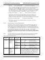
ALSPA MV3000 Demonstration Case
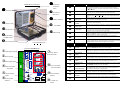
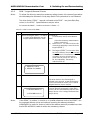
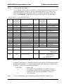
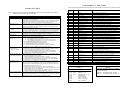
Panel Item
No.
Panel Item
Area
③
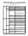
Plant Digital
Inputs
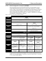
4. Switching On and Demonstrating
Specific panel
name
INPUT 1
Function / Use in the case (@ default)
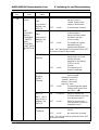
ON
- lit Red -
When set to “remote”,
the stop circuit is
“made” and the case
output is able to start.
OFF
- not lit -
A remote stop is issued
ON
- lit Green -
When set to “remote”,
a start request is
issued, the case output
will start if the stop
circuit is made.
OFF
- not lit -
The output will remain
started (latched) if
pressed and released.
Stop
only works in
Remote, see
INPUT 4
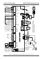
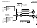
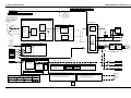
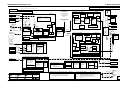
SEE
CONTROL
BLOCK
DIAGRAMS
- SHEET 2 AND
CONTROL
FLAG DATA
IN SECTION
5
INPUT 2
Start
only works in
Remote, see
INPUT 4
Note: This input should be pulsed ON then OFF
to perform a start (if stop made).
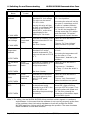
INPUT 3
ON
- lit Yellow -
The speed reference
being used in the case
can be reversed,
depends on the setting
of P5.11 for its
function.
OFF
- not lit -
The reference will
remain unaffected.
ON
- lit Yellow -
OFF
- not lit -
The start/stop and speed
reference will come from
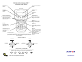
the DDM™ (❾).
ON
- lit Yellow -
When in remote, the
4-20mA reference is active
on Analogue input 2.
OFF
- not lit -
When in remote, the +/10V reference is active on
Analogue input 1.
ON
- lit Yellow -
A trip reset pulse is
issued.
OFF
- not lit -
No reset pulse is issued
Reverse
INPUT 4
Keypad
(DDM™)
/Remote
INPUT 5
The start/stop controls
and the speed
reference come from
“remote”, which, at
default, is the panel
plant I/O area.
Ref 1 /Ref 2
only works in
Remote, see
INPUT 4
INPUT 6
Trip Reset
Note: This input should be pulsed ON then OFF
to perform a reset.
Issue (05/01)
Demonstration Case User Manual (T1691)
Page 4-3