1
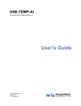
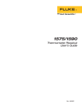
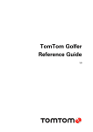
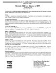
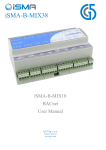
Page 2 · 286 TECMount User’s Manual Table of Contents Introduction ............................................................................................... 3 Installation and Use................................................................................... 4 Mounting Plates ........................................................................................ 8 Connector Pin-Outs .................................................................................. 8 Using the Aux and Ext Sensor Inputs ..................................................... 10 Technical Specifications ......................................................................... 11 Using the Thermistor on Standard Versions ........................................... 12 Using the RTD on 150°C Versions .......................................................... 13 Mechanical Drawings .............................................................................. 15 Warranty .................................................................................................. 19 Service and Support ............................................................................... 19 286 TECMount User’s Manual · Page 3 Introduction Thank you for choosing the 286 TECMount from Arroyo Instruments. The 286 TECMount is designed for high performance and long term use. The 286 TECMount integrates high power Peltier coolers for precise control and substantial heating and cooling capacity for your powerful devices. The standard 286 TECMount has an operating range of +15°C to +85°C, and the high temperature (-150) version allows operation up to 150°C, covering a broad range of temperature control needs. The 286 TECMount comes standard with an integrated fan for additional cooling capacity. When used with the Arroyo Instruments TECSource temperature controllers, no additional power supply is needed to power the fan, or use a standard external 12V DC power supply when connecting to other temperature controllers. The 286 TECMount also offers all the features you would expect from a modern diode fixture, including: Hard nickel over 100% oxygen free copper thermal plate. M Series accessories for quickly adapting the mount to your application Designed to be quickly integrated with Arroyo’s TECSource instruments. Industry-standard D-sub connector and pin-outs allow for quick integration into your application. Page 4 · 286 TECMount User’s Manual Installation and Use Consider how you plan to integrate the fixture into your application: Set it on your bench or optical table? Bolted to an optical table? Mount the cold plate horizontal or vertical? Mount to other instrument such as an integrating sphere? The 286 TECMount comes standard with the M Series accessory kit, which you can use to do many of these configurations. There are also several ¼”-20 mounting holes on the sides and face of the fixture, and four 8-32 mounting holes on the bottom of the fixture (the same holes used by the feet or posts). Setting on a bench or optical table This is the simplest of configurations. Using the MP-2.00 posts, thread them into the four 8-32 holes on the bottom of the fixture. Next, using the 1/2”x 8-32 screws, a lock washer, and a flat washer, mount the feet to the bottom of each of the posts. 286 mounted on posts and feet 286 TECMount User’s Manual · Page 5 Bolting to an optical table This configuration is very similar to the one above, but instead of the feet, you will use the MB-286 base. Start with the MP-2.00 posts, threading them into the four 8-32 holes on the bottom of the fixture. Next, using the 1/2”x 8-32 screws, mount the MB-286 base to the four posts. 286 mounted on posts and base Page 6 · 286 TECMount User’s Manual Mounting the cold plate vertically For applications that require a vertical cold plate, you can use the MB-286 base with the MR-1.50 riser to mount the 286 on its side. Set the 286 upside down, setting it on a soft cotton cloth to prevent scratching of the cold plate. There are two ¼”-20 mounting holes on the bottom of the fixture. Align the MR-1.50 riser to these two mounting holes and gently set the MB-286 base on top of that, holing it with one hand to stabilize it. Slide in one 2” ¼-20 bolt and turn a few times to get the threads started. Side in and start the second bolt, and then tighten both bolts. 286 mounted vertically on riser and base Mounting to an integrating sphere or other assembly In the case of mounting to another piece of equipment such as an integrating sphere, the 286 features a number of mounting holes on the front, rear, top, and bottom surfaces of the fixture. See the drawings in the Mechanical Drawings section below for more details on the size and location of the mounting holes. Fan and Airflow The 286 uses a high volume fan for cooling of the heat sink. For full performance, you must place the sides and bottom of the 286 at least 2” away from any other surface, or airflow will be constricted. If you are using an Arroyo Instruments TECSource temperature controller, the fan can be powered directly from the TECSource. You will need to enable the 286 TECMount User’s Manual · Page 7 fan supply in the TECSource menu – see the TECSource manual for additional details on how to do that. If you are using a third-party temperature controller, then you will need to provide a 12V DC power supply through the 17W2 connection. See the pin-out later in this document for the fan pin assignments. Connecting to the TEC Controller: Next, connect the 286 TECMount to your temperature controller. The 5300-0824 TECSource is the recommended controller for this mount, although it will work with most temperature controller controllers designed for TEC applications, so long as the current and voltage requirements are met, which is a minimum of 8A and 24V. Make sure the temperature controller’s current limit is set no higher than 14.8A, the maximum for this mount. If using an Arroyo TECSource, change the Mount setting in the menu to either 286 or 286-150, depending on which mount type you have, and the 5300 will be automatically configured for the mount. Where possible, we recommend the use of Arroyo Instruments TEC cables. When connecting to a 5300 Series TECSource, use p/n 1262-17W2. NOTE Earth Grounding Considerations The 17W2 connector shell is electrically connected to the housing. Depending on the wiring of your cables and instruments, this may or may not provide earth grounding of the fixture. Make sure the cable shell is earth grounded on both ends of the cable, and that the instrument makes connection from its connector to earth ground. NOTE Arroyo Instruments offers TEC cables designed to connect directly between our TECSource products. If you use your own cables, ensure the connections are properly made between the instrument and the mount, and that proper grounding techniques are used. The pin-out of the connectors can be found later in this document. Page 8 · 286 TECMount User’s Manual Mounting Plates The 286 TECMount is available in a standard bread board configuration with M3 holes on 10mm centers. Custom versions of the cold plate are available, contact the factory for details. Your 286 may be configured with a custom mounting plate, and if so, this manual should be accompanied by drawing for your plate. Connector Pin-Outs The 286 employs two connectors: a 17W2 for the temperature controller interface, and a 4-pin Phoenix quick disconnect for external/auxiliary sensor inputs. 286 Connectors 286 TECMount User’s Manual · Page 9 Temperature Controller Interface Description TE – 8 EGND (Case) Aux Sensor + Fan – 5 4 3 2 1 9 10 11 Fan + 12 Aux Sensor – n/c 13 n/c Remote Sensor + 6 Sensor + Remote Sensor – 14 Sensor – Vsense TE – 7 Vsense TE + Interlock – 15 Interlock + A1 TE + TE + TE – Interlock + (shorted to Interlock –) Vsense TE + Sensor – Sensor + No connection Aux Sensor – Fan + Fan – / Interlock – Vsense TE – Remete Sensor – Remete Sensor + n/c EGND (Case) Aux Sensor + Fan – / Interlock – 17W2 Connector Pin-Out A2 17W2 Pin A1 A2 1 2 3 4 5 6 7 8 9 10 11 12 13 14 15 17W2 Male Interlock and Fan Pins Interlock – and Fan – share a pin, and the same signal is present on both pins 8 & 15. In addition, because Interlock + is shorted to Interlock – inside the mount, pins 1, 8, & 15 are effectively the same on the 286 connector. Auxiliary & External Sensor Interface Phoenix Pin Description 1 Auxilliary Sensor + 2 Auxilliary Sensor – 3 External Sensor + 4 External Sensor – Phoenix 4-Pin Connector Pin-Out Sensor Polarity and 4-Wire Connections While the thermistor and RTD inputs are not polarized, when using a 4-wire RTD connection to the 286-xx-150 mount, it is important to properly connect the polarity of the sense wires to the sensor. Pins 4 and 11 should be one polarity (+) and pins 3 and 10 should be the opposite polarity (–). If polarities are not matched, the instrument will indicate a sensor error. Page 10 · 286 TECMount User’s Manual Using the Aux and Ext Sensor Inputs The 286 features a SENSOR switch to quickly switch between internal and external temperature sensors. With the SENSOR switch in the INT position, the internal thermistor or RTD embedded in the cold plate is used to provide the feedback for the temperature controller (pins 3 & 4 [and 10 & 11 on 286-xx-150 models] on the 17W2 connector). With the SENSOR switch in the EXT position, the EXT+ and EXT– inputs on the Phoenix connector are connected to pins 3 & 4 [and 10 & 11 on 286-xx-150 models] on the 17W2 connector. The AUX input is reserved for future use, and is wired directly to the Aux Sensor+ and Aux Sensor– pins of the 17W2 connector. 286 TECMount User’s Manual · Page 11 Technical Specifications 286 TECMount COLD PLATE Standard Plates 286-01 Cold Plate Bread board, M3 holes, 10mm centers TEMPERATURE CONTROL Standard Version Temperature Range (°C) Sensor Type Sensitivity +15 to +85 BetaTHERM 10K3A1IA 10kΩ @ 25°C High Temperature Version Temperature Range (°C) Sensor Type Sensitivity +15 to +150 Platinum RTD 100Ω @ 0°C, 0.00385 Ω / Ω / °C TE Module (at 25°C) Maximum Recommended 14.8A / 32.8V 10A / 28V INPUT CONNECTORS Temperature Controller Ext / Aux Sensor GENERAL Size (H x W x D) [in(mm)] Weight [lbs (kg)] 286, no accessories 286 on base or pedestal 208 on 2” posts and feet 17W2, male Phoenix 4-pin 5.2 (132) x 6.4 (163) x 6.4 (163) 9.8 (4.5) 11.8 (5.4) 10.4 (4.7) Page 12 · 286 TECMount User’s Manual Using the Thermistor on Standard Versions The standard version of the 286 LaserMount is equipped with a 10kΩ negative temperature coefficient (NTC) thermistor, specifically, the BetaTHERM 10K3A1. A thermistor works by translating temperature into resistance, with resistance decreasing as temperature increases (hence the ‘negative coefficient’). Below is the response curve of the thermistor: 50000 Resistance (Ω) 40000 30000 20000 10000 0 -10.00 10.00 30.00 50.00 70.00 90.00 110.00 Tem perature (°C) Resistance vs. Temperature Graph As can be seen be the graph, the resistance of the thermistor drops very quickly. In the typical control range (0°C to 40°C), typical 10K thermistors offer good sensitivity to changes in temperature, and this is the range in which most 10K thermistors are typically used. 10K thermistors can be used at much higher temperatures, but will suffer poorer temperature stability performance because of the lower sensitivity. All Arroyo temperature controllers support operation using a 10μA or 100μA thermistor bias, which limits the upper control range to 450kΩ or 45kΩ, respectively. To minimize noise and maximize stability, you should select highest current while still allowing you full operation across your required temperature range. The typical setting is 100μA, but your application will determine the actual needs. 286 TECMount User’s Manual · Page 13 The Steinhart-Hart Equation As can be seen from the temperature versus resistance graph above, resistance varies inversely with temperature in a non-linear fashion. This relationship can be accurately modeled by polynomial equations, and one such being the SteinhartHart equation: 1 A B * ln( R) C * ln( R) 3 T The coefficients for the BetaTHERM 10K3A1 thermistor are: A = 1.12924x10⁻³ B = 2.34108x10⁻⁴ C = 0.87755x10⁻⁷ These are the default coefficients for Arroyo Instruments temperature controllers. Using the RTD on 150°C Versions The 286-xx-150 LaserMount is equipped with a RTD sensor with a 0.00385 Ω / Ω / °C sensitivity. Like thermistors, RTDs also function by converting temperature into resistance, but unlike thermistors, RTDs increase in resistance as temperature increases. RTDs are also a fairly linear device, meaning they can be used across a much broader temperature control range. As per IEC751, the resistance/temperature relationship is determined using one of two equations, dependent on the temperature or resistance value being measured. For resistances above the R0 value (resistance at 0°C, typically 100Ω, as is the case with the RTD used in the 286-xx-150) of the RTD, the following equation is used: R R0 (1 AT BT 2 ) Below R0, an additional term is added to the equation: R R0 [1 AT BT 2 C (T 100)T 3 ] In both of these equations, R0 is the resistance of the RTD at 0°C, and A, B, and C are the coefficients as defined by IEC751, through regression analysis, or by using the Callendar-van Dusen method. Page 14 · 286 TECMount User’s Manual For the Arroyo Instruments controllers that support RTD sensors, the default coefficients are different for this mount. They must be changed to use the 0.00385 Ω / Ω / °C curve, which has the following coefficients: A = 3.9080x10⁻³ B = -0.58019x10⁻⁶ C = -4.2735x10⁻¹² R0 = 100 These coefficients can be changed in the Sensor menu. 2-Wire versus 4-Wire Measurements One concern in using RTDs are their relatively low resistance (typically 100Ω at 0°C), and small Ω/°C. Because of these two factors, the resistance of the cable used to connect to the sensor can create significant absolute error in the sensor measurement. Most Arroyo Instruments controllers offer two RTD measurement modes: a conventional two wire measurement mode, which is subject to this error, and a four wire measurement mode that uses separate sense and source lines to remotely sense the actual resistance of the RTD and eliminate the cable and connector resistances. In the 286-xx-150 LaserMount, the 4-wire connection is made inside the mount. To use this measurement mode, you must select ‘RTD (4-wire)’ as the sensor type. The drawings below illustrate how 2-wire and 4-wire connections work. Note that 4-wire measurements require all four wires to be brought through the cable to the mount. The 1262-17W2 and 1264 TECSource cables carry these connections through to the mount, but the 1260 cable does not. Temperature Controller Sensor+ Sensor– Mount RTD Sensor RTD 2-wire Measurement Temperature Controller Sensor+ Remote Sensor+ Remote Sensor– Sensor– RTD 4-wire Measurement Mount RTD Sensor 286 TECMount User’s Manual · Page 15 Mechanical Drawings 6.40 163 5.50 140 8X 8-32 UNC 5.20 132 CL SEE DETAIL, PLATE VIEW 5.50 140 CL 5.20 132 .32 8 Top View 6.40 163 Page 16 · 286 TECMount User’s Manual 4.20 107 64 X .10[3] M3X0.5 - 6H .31[8] .25[6] 1.12 28 .72 18 7X .39 10 0 0 286-01 Plate Detail 4.20 107 1.12 28 .72 18 0 0 7X .39 10 286 TECMount User’s Manual · Page 17 .70 18 .40 10 5.00 127 2.50 64 6X 1/4-20 UNC 2.00 51 .50 13 .19 5 Front View 4X 1/4-20 UNC 5.00 127 .70 18 .20 5 .40 10 2.00 51 5.00 127 .63 16 Rear View Page 18 · 286 TECMount User’s Manual Side View 4X 8-32 UNC 5.20 132 5.20 132 Bottom View 286 TECMount User’s Manual · Page 19 Warranty Arroyo Instruments warrants this product to be free from defects in material and workmanship under normal use and service for a period of one (1) year from date of shipment. It does not apply when the product has been misused, altered or damaged by accident or abnormal conditions of operation. If found to be defective during the warranty period, the product will either be repaired or replaced at Arroyo Instruments's option. THIS WARRANTY IS IN LIEU OF ALL OTHER WARRANTIES, EXPRESSED OR IMPLIED, INCLUDING IMPLIED WARRANTIES OF MERCHANTABILITY OR FITNESS FOR ANY PARTICULAR PURPOSE. ARROYO INSTRUMENTS SHALL NOT BE LIABLE FOR ANY INDIRECT, SPECIAL, OR CONSEQUENTIAL DAMAGES RESULTING FROM THE PURCHASE OR USE OF ITS PRODUCTS. Service and Support For service and support, contact your local distributor or Arroyo Instruments. Telephone: Facsimile: Email: Web: Address: +1 (805) 543-1302 +1 (805) 543-1303 [email protected] http://www.arroyoinstruments.com 624 Clarion Court San Luis Obispo, CA 93401 USA Copyright © 2012, Arroyo Instruments. All Rights Reserved P/N 530-1031 Rev C