1
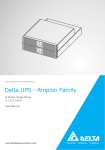
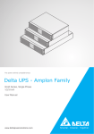
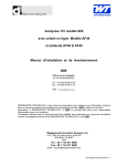
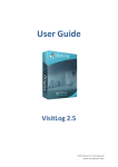
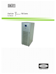
User manual
CellD APS 1500A-230-3 SSW
5012227500_00
Table of contents
1
2
3
4
About this document ........................................................................................... 3
1.1 Preparing for the installation .................................................................... 3
1.1.1
Document content ...................................................................... 3
1.1.2
Contents of packing ................................................................... 3
1.1.3
Before you begin ........................................................................ 4
1.1.4
Unpacking the system ............................................................... 4
Safety instructions .............................................................................................. 5
2.1 About legal and safety information ........................................................... 5
2.2 Legal statements ...................................................................................... 5
2.2.1
Statement of compliance ........................................................... 5
2.2.2
Limitations .................................................................................. 5
2.2.3
Third party devices .................................................................... 6
2.3 Safety instructions .................................................................................... 6
2.3.1
General instructions ................................................................... 6
2.3.2
Specific instructions ................................................................... 8
Installation and commissioning .......................................................................... 9
3.1 CellD APS 1500A-230-3 SSW system configuration ............................... 9
3.2 Installation .............................................................................................. 10
3.2.1
Mechanical assembly .............................................................. 10
3.2.2
Cabling ..................................................................................... 11
3.3 Commissioning ....................................................................................... 13
3.3.1
Starting up the system ............................................................. 13
3.3.2
Switching off the system .......................................................... 14
Troubleshooting ................................................................................................ 15
4.1 About this document .............................................................................. 15
4.2 Standard troubleshooting procedure ...................................................... 15
4.3 System status indications ....................................................................... 15
4.3.1
Static switch module LED indications ...................................... 15
4.3.2
Alarms and fault conditions in static switch module ................ 16
4.3.2.1 Inv. In Use LED flashing ........................................... 16
4.3.2.2 Mains In Use LED flashing ....................................... 16
4.3.2.3 Inv. Failure LED lit .................................................... 16
4.3.2.4 Mains failure LED lit ................................................. 16
4.3.2.5 Fault LED continuously lit ......................................... 16
4.3.2.6 Overload LED lit ....................................................... 17
4.3.2.7 Fault LED flashing with Inv.found LED ..................... 17
4.3.2.8 Fault LED flashing with Inv.failure LED .................... 17
4.3.2.9 Fault LED flashing in opposite phase with Inv.failure
LED ........................................................................... 17
4.3.2.10 Fault LED flashing alone .......................................... 17
4.3.3
Inverter module LED indications .............................................. 18
4.3.4
Alarms and fault conditions in inverter module ........................ 18
4.3.4.1 Fault/overload LED continuously lit .......................... 18
4.3.4.2 Parallel LED flashing alone ...................................... 19
4.3.4.3 Input LED flashing alone .......................................... 19
4.3.4.4 Fault LED flashing with Input LED............................ 19
4.3.4.5 Fault LED flashing with Parallel LED ....................... 19
4.3.4.6 Fault LED flashing with Output LED ......................... 19
4.3.4.7 Fault LED flashing with Output and Parallel LEDs ... 19
4.3.4.8 Fault LED flashing alone .......................................... 19
4.4 User programmable parameters ............................................................ 20
4.4.1
User programmable parameters in static switch ..................... 20
4.4.1.1 Default supply ........................................................... 21
4.4.1.2 Input limits ................................................................ 21
4.4.1.3 Temperature ............................................................. 23
CellD APS 1500A-230-3 SSW Table of contents
4.4.2
5
User programmable parameters in inverter module ................ 24
4.4.2.1 Input voltage ............................................................. 24
4.4.2.2 Output voltage .......................................................... 26
4.4.2.3 Temperature ............................................................. 27
4.5 Contacting Delta customer service ........................................................ 28
Technical specifications, CellD APS 1500A-230-3 SSW ................................. 29
CellD APS 1500A-230-3 SSW Table of contents
1
About this document
1.1
Preparing for the installation
1.1.1
Document content
This document contains the following sections:
•
•
•
•
•
1.1.2
Safety instructions
Product description, Delta outdoor cabinet (only with outdoor cabinets)
Installation and commissioning
Troubleshooting
Appendix
Contents of packing
The package contains the following items:
• System
• Documents: user manual, CD “Extras”, circuit diagram(s), component
layout(s) (CD and appendices on the manual pocket)
Figure 1. User manual and CD
• Possible inverters
• Possible cables (DC supply cables, AC supply cables)
CellD APS 1500A-230-3 SSW About this document
3
1.1.3
1.1.4
4
Before you begin
Step 1
Ensure that you have all the equipment needed to make a proper installation of
the system.
Step 2
Also ensure that grounding terminals, DC and AC distributions are properly
available.
Step 3
Take care that the regulations of IEC 60364 and CENELEC HD384 concerning
installation and assembling of telecommunication and electrical equipment have
been noticed. The local regulations and special instructions must also be noticed
during the work. When choosing the place of the installation, please notice that
the cooling air must flow without restrictions through the ventilation holes. The
system must have enough space in front of it for operation and service functions.
Notice the direction of the cabling and the required space of the other
equipment.
Unpacking the system
Step 1
Check that the received cargo is according to the packing list.
Step 2
Ensure that the rack and the equipment are not damaged during transportation.
CellD APS 1500A-230-3 SSW About this document
2
Safety instructions
2.1
About legal and safety information
Please read all safety and legal information given provided here before working with any
Delta products. Ignoring these instructions may result in damage to the equipment, health
hazards, or loss of life.
These safety instructions are an extension of any national laws governing health and
safety at work and the applicable standards, as well as any regulations of the statutory
authorities.
Installation shall only be performed by trained persons familiar with the local installation
regulations. The local installation regulations must always be followed (covering
installations in the building and main AC distribution panels). It is also necessary to follow
the instructions provided in the system user manual for installation, commissioning,
operation and maintenance.
2.2
Legal statements
2.2.1
Statement of compliance
Please see the relevant product fact sheet for information.
2.2.2
Limitations
The equipment is mainly intended for telecommunications purposes only. The equipment
is not intended for use in applications in which the failure of the equipment could lead to
death, personal injury, or severe physical or environmental damage.
Delta is not responsible for any danger or damage resulting from incorrect installation,
maintenance, operation or usage of the equipment, use beyond its intended purpose,
failure to observe stated instructions, and/or failure to observe the applicable safety
regulations.
Delta is only responsible for components and services provided by Delta. Third party
components and/or services, such as batteries, repair and/or maintenance used in and/or
conducted for the equipment, are not the responsibility of Delta. Furthermore, Delta is not
responsible for any malfunction or danger of, and/or damage to/resulted from the
equipment caused by such third party components and/or services.
Unauthorised modifications to the equipment may result in incorrect operation and/or
performance. The operator is responsible for the consequences of any modification in the
hardware configuration that is made without an agreement with the manufacturer or
authorised representative.
CellD APS 1500A-230-3 SSW Safety instructions
5
Installation, operation and maintenance of the equipment should only be performed by
suitably qualified personnel with appropriate training. The operator is responsible for
ensuring that personnel working with the equipment are provided with appropriate
operation and safety training.
The operator is responsible for ensuring that the location of the system is treated as an
electrical equipment room. These rooms must have appropriate air-conditioning and
restricted access. The operator is also responsible for ensuring that the system rack
doors are securely locked and not accessible to unauthorised persons. The equipment
must be installed on an incombustible base, e.g. on a concrete floor.
If the power supply to the system is not fitted with a disconnecting switch or equivalent
device, the operator is responsible for fitting an appropriate disconnection switch
conforming to the relevant regulations.
2.2.3
Third party devices
Delta is not responsible for devices, such as batteries that are not supplied by Delta.
Delta is not responsible for any danger or damage resulting from devices not supplied by
Delta.
2.3
Safety instructions
Warnings, cautions and notes are used to identify important information. They are
classified as follows:
Warning! A warning means that injury or death is possible if the information or
instructions are not obeyed.
Caution! A caution means that damage to equipment is possible if the
information or instructions are not obeyed.
Note! Notes are additional information which may be useful to the operator.
2.3.1
General instructions
Warning! Hazardous voltages are present within the equipment when a source
of electrical power is applied.
There is the risk of electrical shock from the main power supply and/or batteries.
When working on equipment with power applied, supervision of personnel is required.
The supervisor must be capable of providing first aid in the event of electrical shock.
Provision of an emergency switch or disconnection strap is not sufficient protection.
6
CellD APS 1500A-230-3 SSW Safety instructions
There is increased risk of accidents and electrical hazards when working on compact
equipment due to the close proximity of components. Operation of compact equipment
requires extra attention to safety.
Warning! Protective shields and other safety devices provided with the
equipment must be in place when the equipment is operated.
The power system may have dual energy supply. Hazardous voltages may be present at
the main power connector and within the equipment for up to 10 seconds after
disconnecting the power supply. The operator is responsible for securing the proper
precautions for maintenance or service purposes.
During installation and maintenance, protective shields may be temporarily removed. Use
suitable insulated tools and appropriate protective clothing. Handle fuses only with tools
provided for this purpose, for example, load-break switch handles.
Adequate insulation from ground potential (earth) must be provided when working on the
equipment.
Warning! High temperatures present.
Localized areas of high temperature (> 70 °C) may occur within the
rectifier/inverter/distributor rack. Take precautions against accidental burns.
Warning! Moving parts
Devices, such as rectifiers and environmental control for cabinets contain fans. These
may also continue to rotate for some time after the power has been removed.
Warning! Heavy equipment
The weight of the equipment requires suitable safety considerations. Additional personnel
or lifting equipment may be needed. Where required, the weight of equipment is stated on
the front of the unit.
Warning! Sharp edges
Equipment racks may have sharp edges. We recommend you to wear gloves.
Caution! Do not restrict air flow. Fit blank panels for empty rectifier slots to
ensure correct air circulation inside the cabinet.
Caution! Use only suitable measuring devices.
Calibrate measuring devices regularly.
CellD APS 1500A-230-3 SSW Safety instructions
7
2.3.2
Specific instructions
Please observe all warning labels and notifications on the equipment.
Additional warnings, cautions and notes specific to certain equipment and/or conditions
are described in the context of the relevant instructions.
Please read all documentation relevant to the given task.
Where devices, such as batteries, that are not supplied by Delta are used, please read
and observe all safety notices and instructions supplied by the appropriate manufacturer
or supplier.
8
CellD APS 1500A-230-3 SSW Safety instructions
3
Installation and commissioning
3.1
CellD APS 1500A-230-3 SSW system configuration
Figure 2. Inverter system CellD APS 1500A-230-3 SSW front view
Figure 3. Inverter system CellD APS 1500A-230-3 SSW back view
CellD APS 1500A-230-3 SSW Installation and commissioning
9
1. Grounding mounting point
11. 19” 1.5U shelf for inverter and 7.5 kVA
static switch modules
2. DC supply plus connection
12. 19” 1.5U shelf for two inverter modules
3. DC supply minus connections
13. Plug-in inverter module 1.5 kVA
4. DC supply inverter pre-fuses
14. Plug-in static switch module 7.5 kVA
5. Optional AC Mains fuse and terminals
15. Standard 19” adjustable mounting
brackets
6. Optional distribution socket
16. Optional slide rails
7. Optional RCCB for socket
17. Place for inverter module
8. AC distribution breakers
18. Remote alarm terminals
9. Optional manual by-pass switch
19. AC distribution PE-terminals
10. Inverter monitoring RS 232
20. Optional AC distribution N-terminals
Note! The bracketed [ ] numbers in this instruction refer to the corresponding
numbers in Figure 2, Figure 3, Figure 4 and Figure 5.
3.2
Installation
3.2.1
Mechanical assembly
10
Step 1
Prepare the system for 19” rack assembly by standard mounting brackets [15] or
optional slide rails [16]. Mounting brackets have several possible mounting
positions in depth dimension. The slide rails are mounted into front position.
Step 2
Lift the unit into 19” cabinet. Fasten the mounting screws. When using slide rails,
secure the assembly into the rack by fastening the inverter shelves into the rack.
CellD APS 1500A-230-3 SSW Installation and commissioning
Figure 4. The basic 19 inch mounting flanges can be on several depth positions
Step 3
3.2.2
Remove the roof and any protective covers from the system unit in front of the
distributions and connections.
Cabling
Warning! All circuit breakers must be in the OFF position and all fuses must be
removed.
Step 1
Connect the frame grounding [1] to the main grounding busbar. Positive
DC supply terminals are already connected to ground via inverters.
Figure 5. Grounding connection for main PE-cable
CellD APS 1500A-230-3 SSW Installation and commissioning
11
Step 2
Connect the AC mains supply cables to the AC power terminals [5]. See Table 1
for information about the correct main power supply fuses and type of cables to
use.
Note! Use the wiring diagram, supplied with the installation documentation, to
ensure the DC and optional AC power supplies have been correctly connected.
Note! The AC supply connection of the static switch is always a 1-phase
connection. The tables below show the recommended fuse size of connection
and the minimum cable cross sections.
AC- and DC-supply connections
Mains fuse
Cable cross section
(minimum)
AC mains supply for static switch
40A gL/gG
3 x 6 mm²
DC supply separately for each inverter
n * 40A
n x 6 mm²
DC supply common for max. 2 inverters
80A
1 x 16 mm²
DC supply common for max. 3 inverters
120A
1 x 35 mm²
DC supply common for max. 4 inverters
160A
1 x 50 mm²
Table 1. AC and DC input cable and fuse size rule
Note! The maximum cable size for the connectors on the neutral and
PE -bus bars of the distribution MCB is 16 mm².
Note! The DC supply of the system is positively grounded.
Step 3
Connect the DC supply minus cable(s) into the DC supply common bus bar or
separate pre-fuse for each inverter module.
Step 4
Connect the remote alarm cables to the remote alarm terminals [18].
Note! Alarms are connected in normal operation so that the alarm circuit is
closed (NC), and in case of registered fault the circuit is open (NO).
12
Step 5
Connect the load distribution cables to the PE-bus bar [19] and load breakers of
the system. When the AC distribution is protected with 1P MCB’s the system has
separate neutral (N- ) [20] and earth (PE-) bus bars [19].
Step 6
Connect the line wires directly to the connections of the AC distribution circuit
breakers or fuses [8].
Step 7
Install all protective covers to the equipment.
CellD APS 1500A-230-3 SSW Installation and commissioning
3.3
Commissioning
3.3.1
Starting up the system
Taking the system into use is presented below step by step.
Step 1
Check that all inverter module main switches are in the OFF position.
Step 2
Plug in the inverter modules to the inverter shelves [14] of the system. The
modules are secured with a lever on the front.
Step 3
Plug in the optional static switch to the inverter shelves [14] of the system. The
static switch is situated on the right-hand-side slot in the upper shelf.
Note! One inverter shelf version has only two slots for inverter modules without
option for static switch. The modules are secured with a lever on the front.
Warning! Protective shields and other safety devices provided with the
equipment must be in place when the equipment is operated.
During installation and maintenance, protective shields may be temporarily removed.
Suitable insulated tools and appropriate protective clothing must be used.
Check that the connections are made according to the installation instructions and the
wiring diagram.
Step 4
Switch on the optional AC mains power supply to the system.
Step 5
Switch on all the DC input breakers [4].
Step 6
Turn all DC INPUT rocker switches on inverter modules to the ON position.
Operate the switches in min. 1s sequence in the preferred bus address order.
When all parallel LED lights stop flashing the inverter system is ready for
operation.
Step 7
Press TWO AC-ON buttons simultaneously on separate inverter modules at
least 1s to turn on the output voltage. The output LEDs turn on.
Step 8
Turn the manual by-pass switch step-by-step to the AUTO position. That will
start the static switch automatically.
Note! Stay at the minimum 2s in the position SYNC for synchronizing the
inverter system with AC mains.
Step 9
Turn all required AC load breakers on.
Step 10 Check the output load level from the LED bar indicator on the inverter modules.
CellD APS 1500A-230-3 SSW Installation and commissioning
13
3.3.2
14
Switching off the system
Step 1
Turn off the output of all inverters at the same time by pressing TWO AC-OFF
buttons on the inverter modules at least 1s.
Step 2
Inverters can be shut down totally by turning all DC input rocker switches to the
OFF position.
Step 3
The optional static switch can be turned off by shutting all AC inputs. Turn the
manual by-pass switch step-by-step to the OFF position.
CellD APS 1500A-230-3 SSW Installation and commissioning
4
Troubleshooting
4.1
About this document
This document provides only basic information to assist in identifying and recovering from
potential problems with Delta Energy Systems. The most accurate information can be
found in the documents of the inverter module and static switch supplier. Refer to the
User manual, DAC60000 inverters & DAC60000 dual inverters and User manual, BPU
69000 6kVA static switch & BPU 69000 dual 7.5kVA static switch & BPU 69000 dual
30kVA static switch for more information.
4.2
Standard troubleshooting procedure
Troubleshooting is always initiated by an alarm. Alarms may be monitored remotely or
locally. Relay alarms trigger LEDs locally, but can also be wired for remote monitoring. As
a standard a Delta Energy Systems inverter system includes terminal blocks for alarm
connections.
Diagnostic for static switch module
If the static switch recognizes a fault condition it indicates it by the front panel LEDs. In
case of a fault the alarm can be reset by resolving the problem in the system. Refer to the
User manual for more information.
Diagnostic for inverter module
If the inverter recognizes a fault condition it uses the front panel LEDs in indicating it to
the user. In case of a fault the alarm can be reset by resolving the problem in the system.
In case of an alarm on the inverter (refer the User manual) press shortly the ON button. If
this procedure does not help, try shutting down the inverter by turning the Power On
rocker switch to the OFF position, and then restart the inverter by turning the Power On
rocker switch back to the ON position. Refer to the User manual for more information
about alarms.
4.3
System status indications
4.3.1
Static switch module LED indications
Overload: The inverter system is overloaded or would be overloaded if it was used to
supply the load or the load current exceeds the maximum allowed output current of the
bypass.
Mains failure: Mains voltage or frequency is not in allowed limits. Use RemoteMonitor
software for more accurate information.
Mains in use: The output of the bypass is supplied from the mains. If the LED is
continuously lit it is the default supply. If the LED flashes it indicates that it is the backup
supply.
CellD APS 1500A-230-3 SSW Troubleshooting
15
Synchronized: Inverter output voltage is synchronized to the mains voltage.
Fault: Flashes when there is a fault in the system. Use RemoteMonitor software for more
accurate information. If this LED is continuously lit the microprocessor of the bypass is
not working. Try to press the Reset button in the bottom of the front panel.
Inv. failure: Inverter output is off, inverter voltage or frequency is not in allowed limits or
the communication between the bypass and the inverter is not working. Use
RemoteMonitor software for more accurate information.
Inv. in use: The output of the bypass is supplied from the inverter. If the LED is
continuously lit it is the default supply. If the LED flashes it indicates that it is the backup
supply.
Inv. found: Bypass has found inverters connected to the control bus. If this LED flashes
with the fault LED the communication bus is disconnected or there are other problems on
the communication bus.
4.3.2
Alarms and fault conditions in static switch module
4.3.2.1
Inv. In Use LED flashing
Load is supplied from the inverter supply, which is working as a backup supply. If the
Mains failure LED is not lit the bypass is going to switch to the mains supply (default
supply) when the user programmable delay is expired (see section 4.3.3.1 "User
programmable parameters).
4.3.2.2
Mains In Use LED flashing
Load is supplied from the mains supply, which is working as a backup supply. If the
Inverter failure LED is not lit the bypass is going to switch to the inverter supply (default
supply) when the user programmable delay is expired (see section 4.3.3.1 "User
programmable parameters).
4.3.2.3
Inv. Failure LED lit
Inverter output is off, inverter voltage or frequency is not in allowed limits or the
communication between the bypass and the inverter is not working. Use RemoteMonitor
software for more accurate information.
4.3.2.4
Mains failure LED lit
Mains voltage or frequency is not in allowed limits. Use RemoteMonitor software for more
accurate information.
4.3.2.5
Fault LED continuously lit
The microcontroller of the bypass is not working. Try to press the Reset button to return
to normal operation.
16
CellD APS 1500A-230-3 SSW Troubleshooting
4.3.2.6
Overload LED lit
Inverter system is overloaded or would be overloaded if the load was switched to the
inverters. This LED is lit also if output power exceeds the maximum power of the bypass.
4.3.2.7
Fault LED flashing with Inv.found LED
Communication with inverters does not work properly. Check the Control bus cable.
4.3.2.8
Fault LED flashing with Inv.failure LED
Inverter AC output on but not connected to bypass.
4.3.2.9
Fault LED flashing in opposite phase with Inv.failure LED
Voltage on inverter AC bus has wrong polarity. Check the cables.
4.3.2.10
Fault LED flashing alone
The Fault LED flashes a number of times and after a short pause repeats the sequence.
Number of flashes indicates the fault. In the following is listed the numbers of flashes and
the corresponding faults. For more accurate fault information use the RemoteMonitor
software.
(1
Reserved)
2
Over-temperature. Temperature is over the Over temperature alarm level (user
programmable parameter).
4
Unit lost. One or more inverter modules disappeared from the system because of a
fault.
6
AC power switch failure. One of the power switching thyristors or their drive circuit
is not working properly. Press the Reset button through the hole in the right bottom
corner of the panel. If the fault repeats the bypass needs service.
7
Control bus transmitter/receiver HW failure.
10
Internal non-volatile RAM read or write error. If the bypass parameters could not be
read from the non-volatile memory the bypass uses factory default parameters until
new parameters are written by the RemoteMonitor software. Other errors may
affect internal e.g. history file but not prevent output voltage generation.
11
Fan fault or the fan option is not properly installed.
12
Malfunction of internal circuits. Bypass is not working properly.
13
Incompatible software or parameters. The system has modules that cannot operate
with each other because of incompatible parameter sets or software versions.
CellD APS 1500A-230-3 SSW Troubleshooting
17
4.3.3
Inverter module LED indications
Overload/fault: If the inverter is overloaded or it has turned the output voltage off
because of too long overloading this LED is continuously lit. The output LED and the load
LEDs (below) tells if the output is still on.
During fault conditions this LED flashes. Refer to section 4.3.4 "Alarms and fault
conditions in inverter module" for more accurate information about indicating fault
conditions.
Output power: This 4 LED bar display indicates the output loading in percent compared
to nominal apparent and active power ratings.
Output on: This LED is lit when the output voltage is on. In parallel operation it flashes
with the fault LED when there is a fault in the output connection. Refer to section
4.3.4 "Alarms and fault conditions in inverter module" for more accurate information about
indicating fault conditions.
Input on: This LED is lit when the input voltage is connected and is in acceptable limits.
Refer to section 4.3.4 "Alarms and fault conditions in inverter module" for information
when this LED flashes.
Parallel: This LED flashes slowly at start-up when the inverter is listening to the
communication bus to find other inverters in the parallel connected system. This happens
also even if the inverter is a stand-alone type. The stand-alone inverter checks that it is
not connected to any other inverter.
After a slow flash the parallel LED is turned off if there are no other inverters on the
communication bus, and turned on if it recognizes another inverter on the bus and
synchronizes to it.
4.3.4
Alarms and fault conditions in inverter module
If the inverter recognizes a fault condition it uses the front panel LEDs to alarm the user.
In the following the possible alarms and the corresponding faults are described. In case of
fault the alarm can be reset by resolving the problem or in case of inverter missing (fault 4
in section 4.3.4.8. "Fault LED flashing alone") by pressing shortly the ON button. If these
solutions do not help, try shutting the inverter off by turning the Power On rocker switch to
the OFF position and then restart the inverter by turning the Power On rocker switch to
the ON position.
More accurate fault information is available through the RS-232 communication port by
using the RemoteMonitor software. In addition, general status information including
alarm/no alarm data is available through the RS-232 port by using a very simple protocol
(ask for DAC60000 Status Query Protocol description).
4.3.4.1
Fault/overload LED continuously lit
Inverter is overloaded. If all the load LEDs and output LED are lit, the inverter is still
supplying AC power to output. If they are not lit the inverter has turned the output off.
18
CellD APS 1500A-230-3 SSW Troubleshooting
4.3.4.2
Parallel LED flashing alone
This LED flashes slowly at start-up when the inverter is listening to the communication
bus to find other inverters in the parallel connected system. This check is done also by a
stand-alone model.
4.3.4.3
Input LED flashing alone
Output voltage is turned off because of too low or too high input voltage. Input voltage is
not anymore outside the stop limits but it is still outside the start limits or automatic start is
not enabled.
4.3.4.4
Fault LED flashing with Input LED
Input voltage is below the low input voltage stop level or above the high input voltage stop
level, and the output voltage will be turned off after the preset delay (user programmable)
if it is still on. Output LED indicates the status of the output voltage.
4.3.4.5
Fault LED flashing with Parallel LED
Communication with other inverters or external bypass switch does not work properly.
4.3.4.6
Fault LED flashing with Output LED
Output cable not connected. In the parallel operating inverter system a module that has
not output on does not find the output voltage generated by the other modules in the
output connector.
4.3.4.7
Fault LED flashing with Output and Parallel LEDs
Communication cable not connected. There is AC voltage generated by other modules
present in the output connector even this module gets no information from the other
modules.
4.3.4.8
Fault LED flashing alone
The fault LED flashes a number of times and after a short pause repeats the sequence.
Number of flashes indicates the fault. In the following are listed the numbers of flashes
and the corresponding faults. For more accurate fault information use the RemoteMonitor
software.
(1
Reserved)
2
Over-temperature. Temperature is over the Over-temperature alarm level (user
programmable parameter).
3
Earth short. One of the output connectors is connected to ground when Earth short
this alarm is enabled (user programmable parameter).
CellD APS 1500A-230-3 SSW Troubleshooting
19
4
Unit lost. One or more inverter modules or the external bypass disappeared from
the system because of a fault. The other modules alarm.
5
Load sharing fault. Output loadings of individual modules can not be automatically
adjusted to be approximately equal. Check that all the output cables are
connected.
6
Malfunction of internal power stage. Try once to restart inverter.
7
Control Bus hardware failure or strong external disturbance. Try once to restart
inverter.
8
Temperature measurement failure. One of the two temperature measurements has
failed.
9
Long On or Off key. The Output On or Off key has been continuously pressed for
more than 5 minutes. Probably there is mechanical failure. The key is now ignored.
10
Internal non-volatile RAM read or write error. If the system parameters (output
voltage and frequency etc.) could not be read, the inverter cannot turn the output
on before new parameters are written by the RemoteMonitor software. Other errors
may affect internal e.g. history file but not prevent output voltage generation.
11
Fan fault or the fan option is not properly installed.
12
Malfunction of internal circuits. Inverter is not working properly.
13
Incompatible software or parameters. The system has modules that can not
operate with each other because incompatible parameter sets or software versions.
14
Internal bypass option malfunction or not properly installed.
4.4
User programmable parameters
4.4.1
User programmable parameters in static switch
The user can change many parameters that affect the behaviour of the bypass with the
RemoteMonitor software. All parameters can be modified any time. In order to check and
modify the user programmable parameters you need the DAC60000 RemoteMonitor
software. This easy-to-use monitor and control software for Windows® environment gives
you a safe way to change parameters. However, you must understand what you are
doing before you change the parameters. Values that are OK in another system may lead
to unwanted behaviour in another system. Refer to the DAC60000 RemoteMonitor User
Manual for details how to read and modify the parameters.
ALL PARAMETERS CAN BE SAFELY MODIFIED WHEN SYSTEM IS RUNNING AND
OUTPUT VOLTAGE IS ON.
20
CellD APS 1500A-230-3 SSW Troubleshooting
Note! Parameters have default values programmed at factory and the bypass
will operate properly without any programming by user. However, if needed, the
user can tune the behaviour of the bypass by modifying the following
parameters. Also restoring factory setup can be easily done by the
RemoteMonitor software.
4.4.1.1
Default supply
The user can select which supply is the default supply (used when both AC supplies are
present) and which is the backup supply.
Load level to switch back to inverters after overload
If inverter loading is over 100 % inverter output will be turned off after a while and bypass
switches to the mains supply. This parameter defines how low the output power has to
decrease before switching back to inverters. This hysteresis may be necessary to prevent
oscillation because there may be a difference between mains and inverter voltages, and
also the power taken by the load may change when switching to the other supply. So it is
possible that when the mains supply is used the loading is lower than 100 % of inverter
nominal load, even if it is higher than 100 % when inverter supply is used.
Note! There is a restart delay in the inverter parameters. It is not possible to
switch back to inverters before this delay has expired and inverters have
restarted.
Delay to return from backup supply to default supply
When the default AC supply has failed and is restored, the bypass switches back to the
default supply after this delay. When there are disturbances in the mains voltage these
problems may repeat several times during some seconds before the condition is totally
over. To prevent unnecessary switching to the backup supply and immediately back to
the default supply, the user can set this delay so that the bypass waits for some seconds
before switching back to the default supply. The delay can be from 2 to 60 s. During this
delay the Inv. In Use or Mains In Use LED is flashing but Inv. Failure and Mains Failure
leds are off.
4.4.1.2
Input limits
4.4.1.2.1
Mains
Mains RMS min and max
Minimum and maximum allowed mains RMS voltage before switching to the inverter
supply.
Mains Hysteresis low and high
Hysteresis affects the limit at which the mains voltage is considered good if it was out of
the allowed limits. E.g. if Mains RMS min is 200 V and Hysteresis is 10 V, the mains
voltage must rise above 210 V before it is accepted again. If the hysteresis is too small
CellD APS 1500A-230-3 SSW Troubleshooting
21
the system will oscillate when mains voltage drops slowly under the minimum level.
E.g. in this case when the mains voltage comes down to 199 V the bypass switches to
the inverter supply. Immediately the mains voltage jumps higher than 200 V because the
voltage drop caused by the load current and the mains supply impedance is not present
anymore. If there is a too small hysteresis the bypass switches back to mains and the
sequence repeats.
The best hysteresis value depends on the load and mains impedance. You can find the
best hysteresis value at the low limit in a very simple way. Just connect the normal load to
both supplies by changing the Default supply parameter with the RemoteMonitor
software, and see how much mains voltage varies. Then use a little bit higher value as
hysteresis. The mains voltage is seen in the main window of the RemoteMonitor.
The Hysteresis high parameter is not so important because there is no similar problem
with the higher limit.
Reaction delay before switching to inverters
Delay to wait before switching to inverters when using mains as default supply and the
instant value of the mains voltage goes out of the allowed limits. User can adjust the
delay according to sensitivity of the load. Too short delay may cause unnecessary
transfers to inverters if there are short disturbances in the mains. Minimum delay is 1 ms.
Note that the real transfer time is this reaction delay time + 1 ms for switch over.
Maximum programmable value is 20 ms. However, long delay time is not accurate. If the
delay time is more than 8 ms, there is always one zero crossing in the delay period. Near
zero crossings a zero mains voltage is always acceptable and the delay counter does not
count. This lengthens the actual delay time. If the delay time is more than approx.
10-15 ms it has no effect anymore because the RMS value measurement reacts faster.
Mains freq. min and max
Minimum and maximum accepted mains frequency. If mains frequency is within these
limits the bypass synchronizes inverter output to this frequency. Otherwise the bypass
switches to inverter supply.
Max frequency change rate
Maximum accepted change rate of mains frequency. If mains frequency changes with
higher rate the bypass switches to inverter supply.
4.4.1.2.2
Inverter
Inverter RMS min and max
Minimum and maximum allowed inverter RMS voltage before switching to the mains
supply. The inverter output voltage is normally stable and within the limits. Limits are
necessary to recognize fast voltage drops in fault conditions like very high overload or
accidental loss of inverter DC supply.
22
CellD APS 1500A-230-3 SSW Troubleshooting
Inverter Hysteresis low and high
See Mains Hysteresis low and high parameter. Because it is very unlikely that inverter
output voltage comes to minimum RMS limit without a heavy overload, it is not normally
necessary to adjust these parameters.
Reaction delay before switching to mains
Delay to wait before switching to mains when using inverters as default supply and the
instant value of the inverter voltage goes out of the allowed limits. A too short delay may
cause unnecessary transfers to mains if load takes high inrush currents. Minimum delay
is 1 ms. Note that the real transfer time is this reaction delay time + 1 ms for switch over.
Maximum programmable value is 20 ms. However, long delay time is not accurate. If the
delay time is more than 8 ms, there is always one zero crossing in the delay period. Near
zero crossings a zero voltage is always acceptable and the delay counter does not count.
This lengthens the actual delay time. If the delay time is more than approx. 10-15 ms it
has no effect anymore because the RMS value measurement reacts faster.
4.4.1.3
Temperature
4.4.1.3.1
Over-temperature
Alarm level
Bypass will give over-temperature alarm when any of the two measured internal
temperatures is over this level. Unit degree in C.
Enable shutdown
If shutdown is enabled the bypass will turn its output off to protect the internal
components if the temperature becomes very high.
Note! This feature is not normally needed and exists only in special models.
Standard bypass does not have this feature and it cannot be enabled.
Shutdown level
In special models, if shutdown is enabled, the bypass will automatically turn off its output
when internal temperature rises over this level. Over-temperature alarm will be given if it
is not already on. Normally this value should be set to maximum. Unit degree in C.
4.4.1.3.2
Fans
(Only in the models that have fans installed)
Low speed temperature or always running
Above this temperature the fans start to operate at low speed. Unit degree in C. Selecting
always running will cause fans to run at low speed also in cold environment.
CellD APS 1500A-230-3 SSW Troubleshooting
23
High speed temperature
Above this temperature the fans start to operate at full speed. Unit degree in C.
Temperature hysteresis
When temperature drops this hysteresis (degrees in C) below low speed temperature limit
the fans will stop.
Note! Too small hysteresis may cause fans to continuously going on and off.
4.4.2
User programmable parameters in inverter module
In order to check and modify the user programmable parameters you need the
DAC60000 RemoteMonitor software. This easy-to-use monitor and control software for
Windows® environment gives you a safe way to change parameters without turning off
the output voltage. However, you must understand what you are doing before you change
the parameters. Values that are OK in another system may lead to unwanted shutdown of
your inverter system. Refer the DAC60000 RemoteMonitor User Manual for details how
to read and modify the parameters.
ALL PARAMETERS CAN BE SAFELY MODIFIED WHEN SYSTEM IS RUNNING AND
OUTPUT VOLTAGE IS ON.
Note! Parameters have default values programmed at factory and the inverter
will operate properly without any programming by user. However, if needed, the
user can tune the behavior of the inverter by modifying the following parameters.
Also restoring factory setup can be easily done by the RemoteMonitor software.
4.4.2.1
Input voltage
4.4.2.1.1
Input low
Stop level: Output will be automatically turned off when input voltage becomes lower
than this stop level. Adjustable with 0,1 V step.
Stop delay: Delay before output is turned off after input voltage has become lower than
stop level. Adjustable with 1 s increment from 1 to 65535 s (approx. 18 hours).
Automatic start enable: If this is enabled the inverter output will be automatically turned
on when input voltage becomes higher than input low start level (see below). Otherwise
output stays off until user presses the ON button (or sends Remote On Command from a
remote computer).
Start level: If automatic start is enabled, output will be automatically turned on when
input voltage becomes higher than this start level. Adjustable with 0,1 V step.
Start delay: Delay before output is turned on after input voltage has become higher than
start level. Adjustable with 1 s increment from 1 to 65535 s (approx. 18 hours).
24
CellD APS 1500A-230-3 SSW Troubleshooting
4.4.2.1.2
Input high
Stop level: Output will be automatically turned off when the input voltage becomes higher
than this stop level. Adjustable with 0,1 V step.
Stop delay: Delay before output is turned off after input voltage has become higher than
stop level. Adjustable with 1 s increment from 1 to 65535 s (approx. 18 hours).
Automatic start enable: If this is enabled the inverter output will be automatically turned
on when input voltage becomes lower than Input high start level (see below) after the
output has been automatically turned off because of too high input voltage (higher than
stop level) . Otherwise output stays off until user presses the ON button (or sends
Remote On Command from a remote computer).
Start level: If automatic start is enabled, output will be automatically turned on when
input voltage becomes lower than this start level. Adjustable with 0,1 V step.
Start delay: Delay before output is turned on after input voltage has become lower than
start level. Adjustable with 1 s increment from 1 to 65535 s (approx. 18 hours).
Note! There should be enough hysteresis between the Low Start and Low Stop
levels. 1 - 2 V is normally enough if the supply impedance is low. With higher
input impedance and small hysteresis it is possible that the inverter continuously
turns its output on and off when the input voltage at the inverter input connector
drops when the inverter takes current.
Examples:
- Output on always when possible
Enable automatic starts. Set Input Low Stop level to minimum, Input Low Start level 1-2 V
higher, Input High Stop level to maximum and High Start level 1 V lower.
- Constant backup time for AC loads in battery backup system.
Set input low stop level to a quite high value (e.g. 50 V in 48 V nominal system) and set
long stop delay (e.g. 1800 s). In many cases this will give approximately constant half an
hour backup time. Battery voltage will fall after quite short time under 50 V and then the
delay starts. Rest of the battery capacity is saved for DC loads.
- Delayed AC load startup to make sure that there is enough battery capacity (backup
time) before AC loads are started.
Set input low start level value to high enough to guarantee needed battery capacity.
Another way is to use low input low start level and long start delay to give the charger
time to charge the battery. The best combination depends on the system configuration.
CellD APS 1500A-230-3 SSW Troubleshooting
25
4.4.2.2
Output voltage
4.4.2.2.1
AC Output
Output voltage: Sets the level of AC output voltage in 1 V steps. Can be changed any
time, also when output is on. Output voltage level will change immediately.
Output frequency: Sets the output voltage frequency in 0,1 Hz steps. Can be changed
any time, also when output is on. The frequency is not changed immediately but slowly
with limited speed. Changing the frequency from one end of the allowed frequency range
to another will take some seconds.
4.4.2.2.2
Alarms
Earth short alarm enable: If enabled, the inverter will alarm if the floating output is
shorted to ground. Do not enable this alarm if you connect the N-conductor to ground.
4.4.2.2.3
Overload shutdown
Shutdown delay: During heavy overload (>110 %) the inverter will automatically turn the
output off after this delay. Adjustable with 1 s increment from 1 to 5 s.
Restart attempts (number or continuous): After turning the output off when overloaded
the inverter will automatically turn on the output again. If it is still overloaded it will turn off
the output again. The number of restart attempts can be limited. If this number is reached
the output is not turned on anymore before user presses the ON button(s) (or sends
Remote On Command from a remote computer). Zero value means no automatic restart
attempt after overload. Adjustable from 0 to 254.
Restart delay: Delay after turning off the output before automatic turn on. Adjustable with
1 s increment from double the shutdown delay to 65535 s (approx. 18 hours).
Forget delay: Inverter resets its restart counter when output has been continuously on at
least this delay. Adjustable with 1 min increment from 1 to 65534 min (approx. 45 days).
Examples:
- Overload conditions are common and not serious (e.g. motor startup).
Use maximum overload capability and automatic recovery after overload shutdown. Set
overload shutdown delay to maximum. Set restart delay to minimum. Set number of
restart attempts to continuous or a high value.
- Overload indicates serious fault in system that must be repaired before reconnecting
output voltage (e.g. only short inrush currents exist and supplying current to a failed
device may cause risk of fire hazards)
Use as short overload shutdown delay (1 s) as possible but long enough to supply inrush
currents needed. Set restart attempts to zero.
26
CellD APS 1500A-230-3 SSW Troubleshooting
4.4.2.3
Temperature
4.4.2.3.1
Over-temperature
Alarm level: Inverter will give over-temperature alarm when any of the two measured
internal temperatures is over this level. Unit degree in C.
Shutdown level: Inverter will automatically turn off its output when any of the two
measured internal temperatures rises over this level. Over-temperature alarm will be
given if it is not already on. Normally this value should be set to maximum to get the
specified nominal power at the maximum specified environment temperature. Unit degree
in C.
Restart attempts: After turning off the output because of over-temperature the output will
be turned on again when temperature has dropped enough. If temperature rises over the
over-temperature shutdown level again the output will be turned off again. The number of
restart attempts can be limited. If this number is reached the output is not turned on
anymore before user presses the ON button(s) (or sends Remote On Command from a
remote computer). Zero value means no automatic restart after over-temperature.
Adjustable from 0 to 254.
Restart hysteresis: The output is automatically turned on when the temperature drops
more than this restart hysteresis in degree C.
Forget delay: Inverter resets its restart counter when output has been continuously on at
least this delay. Adjustable with 1 min increment from 1 to 65534 min (approx. 45 days).
Note! Using too small hysteresis value will probably cause unwanted oscillation
that has a period of some seconds.
Using short forget delay with high hysteresis may cause the inverter to always
forget over-temperature conditions before the next can occur. This causes
always continuous restarting.
Examples:
- Inverter running at light constant load and not in high environment temperature
Setting over-temperature alarm level to value not much higher than the normal internal
temperature level (check it with the RemoteMonitor software), an early alarm will be given
if the temperature abnormally rises in the cabinet.
- Inverters running often in high environment temperature and at high load
To prevent unnecessary over-temperature alarms set the over-temperature alarm level to
a high value (0 to 5 degrees below the shutdown level).
- Inverters running at light constant load and not in high environment temperature. More
temperature sensitive AC loads are mounted in the same cabinet.
CellD APS 1500A-230-3 SSW Troubleshooting
27
Set the over-temperature shutdown level to lower value than maximum. This will protect
the AC loads from overheating if the temperature in the cabinet abnormally rises.
Fans (if the fan option is installed)
- Low speed temperature or always running
Above this temperature the fans start to operate at low speed. Unit degree in C. Selecting
always running will cause fans to run at low speed also in cold environment.
- High speed temperature
Above this temperature the fans start to operate at full speed. Unit degree in C.
- Temperature hysteresis
When the temperature drops this hysteresis (degrees in C) below low speed temperature
limit the fans will stop.
Note! Too small hysteresis may cause fans to continuously going on and off.
4.5
Contacting Delta customer service
If an alarm or specific problem cannot be resolved, please contact your nearest Delta
office or Delta representative for further assistance. Please have the system type and
serial number ready before contacting Delta.
28
CellD APS 1500A-230-3 SSW Troubleshooting
5
Technical specifications, CellD APS 1500A-230-3
SSW
3. General
1. Input
DC Voltage range
40 - 72 VDC
Height, overall
6 U (266 mm)
Nominal current
Maximum current
(5 s) *
Terminal
Feeding fuse
(external)
AC voltage, nominal
3 x 35 ADC
Width, overall
19 IN (483 mm)
3 x 50 ADC
Depth, overall
480 mm
Weight, full system
20 kg
3 x 35 mm²
Efficiency
≥ 90 %
1 x 120 A or 3 x 35 A
Operating temperature
-5 to +45 °C
230 VRMS
Relative humidity
95 % max, non cond.
Frequency, nominal
50 Hz
Safety
IEC/EN 60950
Connections
L + N + PE
EMC
EN 300 386-2
AC-input Fuse
40 A
Protection class
IP 20
Indicators
LED
2 x potential free
contact
RS 232 - diagnostic
and configuration
software
API 1500A-230
2. Output
Frequency
230 VRMS ± 1 %
(208 / 220V / 230 / 240
Vrms - configurable)
50 Hz ± 0.05 Hz
Power, nominal *
3000VA / 2400W
Current nominal *
13 ARMS
Manual bypass
Yes
PDU MCB (DPN)
12 pcs / 2 A ... 10 A
Connections
16 mm² (L + N + PE)
Voltage, nominal
Remote alarm
Control and monitoring
See inverter fact sheet
See static switch fact
sheet
SSW 7500A-230
Subject to change without notice.
Ordering information
Product line number
3791244300
Description
APS 1500A-230-3 SSW
CellD APS 1500A-230-3 SSW Technical specifications, CellD APS 1500A-230-3 SSW
29
Our InD, OutD and HelpD series are designed
to complement each other. InD stands for
indoor power systems, while OutD solutions
are created for demanding outdoor use. HelpD
is our global support team; its task is to make
everything easy for you. The full range of
Delta Power Systems keeps you powered and
allows you to concentrate on what is most
important for you – your business.
www.deltapowersolutions.com
*5012227500*