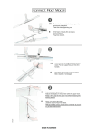
1
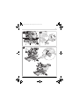
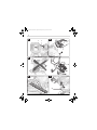
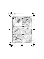
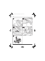
OBJ_DOKU-19912-001.fm Page 1 Monday, January 18, 2010 11:24 AM
,5
50
55 60
o
15
22,5
33
30
45
0
12 12
50
Robert Bosch GmbH
Power Tools Division
70745 Leinfelden-Echterdingen
Germany
45
10 12
40
8 12
35
4 12
6 12
30
25
20
2 12
15
10
5
0
GCM 12 SD Professional
www.bosch-pt.com
1 609 929 W13 (2010.01) PS / 283 WEU
de
en
fr
es
pt
it
nl
Originalbetriebsanleitung
Original instructions
Notice originale
Manual original
Manual original
Istruzioni originali
Oorspronkelijke
gebruiksaanwijzing
da
sv
no
fi
el
tr
Original brugsanvisning
Bruksanvisning i original
Original driftsinstruks
Alkuperäiset ohjeet
Πρωτότυπο οδηγιών χρήσης
Orijinal işletme talimat
OBJ_BUCH-1130-001.book Page 3 Monday, January 18, 2010 10:33 AM
|3
2
6
5
3
1
4
7
8
26
25
9
10
45
30
33,9
11
15
22,5
33
,5
30
45
o
24
50
23
50
55 60
22
12
12 12
50
21
20
19
45
0
10 12
40
18
8 12
35
4 12
6 12
30
25
20
2 12
15
10
17
5
0
13
16
15
14
GCM 12 SD Professional
Bosch Power Tools
1 609 929 W13 | (18/1/10)
OBJ_BUCH-1130-001.book Page 4 Monday, January 18, 2010 10:33 AM
4|
8
27
4
28
29
30
8
43
31
32
42
30 33,
9
45
45
33
3330,5
15
22,5
o
34
5
12 12
50
10 12
8 12
6 12
20
45 40 35 30 25
35
8 12
30
45°-
0
35
10 12
40
12 12
45
50
55
60
0 - 45°
41
1 609 929 W13 | (18/1/10)
40
39
38
37
36
Bosch Power Tools
OBJ_BUCH-1130-001.book Page 5 Monday, January 18, 2010 10:33 AM
|5
50
A
B1
19
2
15
14
19
15
B2
19
C
1
44
45
D1
46
Bosch Power Tools
47
1 609 929 W13 | (18/1/10)
OBJ_BUCH-1130-001.book Page 6 Monday, January 18, 2010 10:33 AM
6|
D3
D2
51
35
48
42
12 12
50
E
45
49 50
9
F
28
30
G
33,9
39
45
3
30
22
21
38
H
53
23
52
54
12 12
10 12
8 12
6 12
4
50
1 609 929 W13 | (18/1/10)
Bosch Power Tools
OBJ_BUCH-1130-001.book Page 7 Monday, January 18, 2010 10:33 AM
|7
I
J
13
45
30
33,9
5
50
55
o
15
22,5
33,
5
30
45
50
45
40
35
30
25
20
0
15
10
5
0
5
18
10
15
20
25
30
35
50
45
40
17
15
15 14
K
1
2
45°-
45
0
0 - 45°
30
33,9
o
15
22,5
33,5
30
45
50
55 60
41
50
12 12
50
45
0
10 12
40
8 12
35
4 12
6 12
30
25
20
2 12
15
10
5
0
16
3
45
30
33,9
o
15
22,5
33,5
30
45
50
55 60
50
12 12
50
Bosch Power Tools
45
0
10 12
40
8 12
35
4 12
6 12
30
25
20
2 12
15
10
5
0
1 609 929 W13 | (18/1/10)
OBJ_BUCH-1130-001.book Page 8 Monday, January 18, 2010 10:33 AM
8|
L
6
M
5
8
N
O
P
50
55
55
25
45
330
33,99
5
50
55 60
45
12 12
10 12
8 12
6 12
4 12
20
2
50
1 609 929 W13 | (18/1/10)
Bosch Power Tools
OBJ_BUCH-1130-001.book Page 9 Monday, January 18, 2010 10:33 AM
|9
Q
R
29
57
58
56 37
36
300
33,9 45
45
3303,5
S1
45
S2
330
33,9
33
,5
30
45
15
22,5
59
50
60
61
62
T2
o
15
22,5
T1
50
63
12 12
50
Bosch Power Tools
45
10 12
8 12
6 12
4 12
5
64
0
2 12
10
5
0
1 609 929 W13 | (18/1/10)
OBJ_BUCH-1130-001.book Page 10 Monday, January 18, 2010 10:33 AM
10 |
U
V
65
5
20
0
2 12
12
15
10
5
0
66
330
33,9
W1
W2
,5
30
33
15
22,5
33
,5
30
67
22
o
45
45
68
12 1
12 12
X
10 12
8 12
6 12
4 12
2 12
50
30
4
69
69
1 609 929 W13 | (18/1/10)
Bosch Power Tools
OBJ_BUCH-1130-001.book Page 33 Monday, January 18, 2010 10:33 AM
English | 33
Safety Notes
en
General Power Tool Safety Warnings
WARNING Read all safety warnings and all
instructions. Failure to follow
the warnings and instructions may result in electric shock, fire and/or serious injury.
Save all warnings and instructions for future
reference.
The term “power tool” in the warnings refers to
your mains-operated (corded) power tool or
battery-operated (cordless) power tool.
1) Work area safety
a) Keep work area clean and well lit. Cluttered or dark areas invite accidents.
b) Do not operate power tools in explosive
atmospheres, such as in the presence of
flammable liquids, gases or dust. Power
tools create sparks which may ignite the
dust or fumes.
c) Keep children and bystanders away
while operating a power tool. Distractions can cause you to lose control.
2) Electrical safety
a) Power tool plugs must match the outlet.
Never modify the plug in any way. Do not
use any adapter plugs with earthed
(grounded) power tools. Unmodified
plugs and matching outlets will reduce
risk of electric shock.
b) Avoid body contact with earthed or
grounded surfaces, such as pipes, radiators, ranges and refrigerators. There is
an increased risk of electric shock if your
body is earthed or grounded.
c) Do not expose power tools to rain or wet
conditions. Water entering a power tool
will increase the risk of electric shock.
d) Do not abuse the cord. Never use the
cord for carrying, pulling or unplugging
the power tool. Keep cord away from
heat, oil, sharp edges and moving parts.
Damaged or entangled cords increase the
risk of electric shock.
Bosch Power Tools
e) When operating a power tool outdoors,
use an extension cord suitable for outdoor use. Use of a cord suitable for outdoor use reduces the risk of electric
shock.
f) If operating a power tool in a damp location is unavoidable, use a residual current device (RCD) protected supply. Use
of an RCD reduces the risk of electric
shock.
3) Personal safety
a) Stay alert, watch what you are doing and
use common sense when operating a
power tool. Do not use a power tool
while you are tired or under the influence of drugs, alcohol or medication. A
moment of inattention while operating
power tools may result in serious personal injury.
b) Use personal protective equipment. Always wear eye protection. Protective
equipment such as dust mask, non-skid
safety shoes, hard hat, or hearing protection used for appropriate conditions will
reduce personal injuries.
c) Prevent unintentional starting. Ensure
the switch is in the off-position before
connecting to power source and/or battery pack, picking up or carrying the
tool. Carrying power tools with your finger on the switch or energising power
tools that have the switch on invites accidents.
d) Remove any adjusting key or wrench before turning the power tool on. A wrench
or a key left attached to a rotating part of
the power tool may result in personal injury.
e) Do not overreach. Keep proper footing
and balance at all times. This enables
better control of the power tool in unexpected situations.
f) Dress properly. Do not wear loose clothing or jewellery. Keep your hair, clothing
and gloves away from moving parts.
Loose clothes, jewellery or long hair can
be caught in moving parts.
1 609 929 W13 | (18/1/10)
OBJ_BUCH-1130-001.book Page 34 Monday, January 18, 2010 10:33 AM
34 | English
g) If devices are provided for the connection of dust extraction and collection facilities, ensure these are connected and
properly used. Use of dust collection can
reduce dust-related hazards.
4) Power tool use and care
a) Do not force the power tool. Use the correct power tool for your application. The
correct power tool will do the job better
and safer at the rate for which it was designed.
b) Do not use the power tool if the switch
does not turn it on and off. Any power
tool that cannot be controlled with the
switch is dangerous and must be repaired.
c) Disconnect the plug from the power
source and/or the battery pack from the
power tool before making any adjustments, changing accessories, or storing
power tools. Such preventive safety
measures reduce the risk of starting the
power tool accidentally.
d) Store idle power tools out of the reach of
children and do not allow persons unfamiliar with the power tool or these instructions to operate the power tool.
Power tools are dangerous in the hands of
untrained users.
e) Maintain power tools. Check for misalignment or binding of moving parts,
breakage of parts and any other condition that may affect the power tool’s operation. If damaged, have the power tool
repaired before use. Many accidents are
caused by poorly maintained power tools.
f) Keep cutting tools sharp and clean. Properly maintained cutting tools with sharp
cutting edges are less likely to bind and
are easier to control.
g) Use the power tool, accessories and tool
bits etc. in accordance with these instructions, taking into account the working conditions and the work to be performed. Use of the power tool for
operations different from those intended
could result in a hazardous situation.
1 609 929 W13 | (18/1/10)
5) Service
a) Have your power tool serviced by a qualified repair person using only identical
replacement parts. This will ensure that
the safety of the power tool is maintained.
Safety Warnings for Sliding Mitre Saws
f Never stand on the power tool. Serious injuries can occur when the power tool tips over
or when inadvertently coming into contact
with the saw blade.
f Make sure that the guard operates properly
and that it can move freely. Never lock the
guard in place when opened.
f Keep hands away from the cutting area
while the machine is running. Danger of injury when coming in contact with the saw
blade.
f Never remove cutting remainders, wood
chips, etc. from the sawing area while the
machine is running. Always guide the tool
arm back to the neutral position first and
then switch the machine off.
f Guide the saw blade against the workpiece
only when the machine is switched on. Otherwise there is damage of kickback, when
the saw blade becomes wedged in the workpiece.
f Keep handles dry, clean, and free from oil
and grease. Greasy, oily handles are slippery
causing loss of control.
f Operate the power tool only when the work
area to the workpiece is clear of any adjusting tools, wood chips, etc. Small pieces of
wood or other objects that come in contact
with the rotating saw blade can strike the operator with high speed.
f Always firmly clamp the piece to be
worked. Do not saw workpieces that are too
small to clamp. Otherwise, the clearance of
your hand to the rotating saw blade is too
small.
f Use the machine only for cutting the materials listed under Intended Use. Otherwise,
the machine can be subject to overload.
Bosch Power Tools
OBJ_BUCH-1130-001.book Page 35 Monday, January 18, 2010 10:33 AM
English | 35
f If the saw blade should become jammed,
switch the machine off and hold the workpiece until the saw blade comes to a complete stop. To prevent kickback, the workpiece may not be moved until after the
machine has come to a complete stop. Correct the cause for the jamming of the saw
blade before restarting the machine.
f Do not use dull, cracked, bent or damaged
saw blades. Unsharpened or improperly set
saw blades produce narrow kerf causing excessive friction, blade binding and kickback.
f Always use saw blades with correct size
and shape (diamond versus round) of arbor
holes. Saw blades that do not match the
mounting hardware of the saw will run eccentrically, causing loss of control.
f Do not use high speed steel (HSS) saw
blades. Such saw blades can easily break.
f Do not touch the saw blade after working
before it has cooled. The saw blade becomes very hot while working.
f Never operate the machine without the insert plate. Replace a defective insert plate.
Without flawless insert plates, injuries are
possible from the saw blade.
f Check the cable regularly and have a damaged cable repaired only through an authorised customer service agent for Bosch power tools. Replace damaged extension
cables. This will ensure that the safety of the
power tool is maintained.
f Secure the workpiece. A workpiece clamped
with clamping devices or in a vice is held
more secure than by hand.
f Keep your workplace clean. Blends of materials are particularly dangerous. Dust from
light alloys can burn or explode.
f Never leave the machine before it has come
to a complete stop. Cutting tools that are
still running can cause injuries.
f Never use the machine with a damaged cable. Do not touch the damaged cable and
pull the mains plug when the cable is damaged while working. Damaged cables increase the risk of an electric shock.
Products sold in GB only: Your product is fitted
with an BS 1363/A approved electric plug with
internal fuse (ASTA approved to BS 1362).
If the plug is not suitable for your socket outlets,
it should be cut off and an appropriate plug fitted in its place by an authorised customer service agent. The replacement plug should have the
same fuse rating as the original plug.
The severed plug must be disposed of to avoid a
possible shock hazard and should never be inserted into a mains socket elsewhere.
Products sold in AUS and NZ only: Use a residual current device (RCD) with a rated residual
current of 30 mA or less.
f Store the machine in a safe manner when
not being used. The storage location must
be dry and lockable. This prevents the machine from storage damage, and from being
operated by untrained persons.
Bosch Power Tools
1 609 929 W13 | (18/1/10)
OBJ_BUCH-1130-001.book Page 36 Monday, January 18, 2010 10:33 AM
36 | English
Symbols
The following symbols can be important for the operation of your power tool. Please memorise the
symbols and their meanings. The correct interpretation of the symbols helps you operate the power
tool better and more secure.
Symbol
Meaning
f Wear ear protectors. Exposure to noise can cause
hearing loss.
f Wear safety goggles.
f Wear a dust respirator.
f Danger area! Keep hands, fingers or arms away from
this area.
Observe the dimensions of the saw blade. The hole diameter must match the tool spindle without play. Do not use
reducers or adapters.
When transporting the machine, hold it only at the locations indicated.
Danger of crushes or contusions! When transporting, ensure that your fingers are positioned around the transport handle.
1 609 929 W13 | (18/1/10)
Bosch Power Tools
OBJ_BUCH-1130-001.book Page 37 Monday, January 18, 2010 10:33 AM
English | 37
Symbol
Meaning
Indicates the individual steps for adjusting the handle.
Indicates the individual steps for adjusting the bevel angle.
Left column:
– Bevel angle range 45°– 0
Saw blade is inclined to the left
Right column:
– Bevel angle range 0 – 45°
Saw blade is inclined to the right
– Bevel angle range 45°+
Complete tilting range of the tool arm
Indicates the position of the locking lever for locking the
tool arm and for adjusting the bevel angle.
Only for EC countries:
Do not dispose of power tools into household waste!
According the European Guideline 2002/96/EC for Waste
Electrical and Electronic Equipment and its implementation into national right, power tools that are no longer usable must be collected separately and disposed of in an
environmentally correct manner.
Bosch Power Tools
1 609 929 W13 | (18/1/10)
OBJ_BUCH-1130-001.book Page 38 Monday, January 18, 2010 10:33 AM
38 | English
Functional Description
Read all safety warnings and all instructions. Failure to follow the
warnings and instructions may result in electric shock, fire and/or serious injury.
19 Mounting holes
20 Fence
21 Fence extension
22 Locking screw for fence extension
23 Quick-action clamp
24 Angle indicator (vertical) for rightward bevel
angle range 0 – 45°
Intended Use
25 Slide device
The power tool is intended as a stationary machine for making straight lengthways and crossways cuts in wood. In this, horizontal mitre angles from –52° to +60° as well as vertical bevel
angles from 47° (leftward) to 47° (rightward)
are possible.
The capacity of the power tool is designed for
sawing hardwood and softwood.
26 Cable holder
The power tool is not suitable for cutting aluminium or other non-ferrous metals or alloys.
33 Angle indicator (vertical) for leftward bevel
angle range 45°– 0
Product Features
The numbering of the components shown refers
to the representation of the power tool on the
graphic pages.
27 On/Off switch
28 Transport safety-lock
29 Adjusting screw of depth stop
30 Transport handle (rear)
31 Locking screw for slide device
32 Scale for bevel angle (vertical)
34 Adjustment knob for 33.9° bevel angle
35 Socket spanner (14 mm)/
Allen key (4 mm)/Phillips screwdriver
36 Lock screw of the length stop
37 Length stop
1 Dust bag
38 Saw-Table extension
2 Allen key (size 1,5 mm)
39 Tensioning lever for saw-table extension
3 Open-end spanner (17 mm; 10 mm)
40 Scale for mitre angle (horizontal)
4 Transport handle (front)
5 Clamp for handle
41 Knob for adjustment of the bevel angle
range
6 Tongue for grade-adjustment of handle
42 Spindle lock
7 Handle
43 Locking lever
8 Button for releasing locking lever 43
44 Extraction adapter
9 Saw blade
10 Retracting blade guard
11 Roller
12 Insert plate
13 Locking bracket
14 Locking knob for various mitre angles
(horizontal)
45 Sawdust ejector
46/47
Phillips screw (attachment of retracting
blade guard)
48 Hexagon bolt for saw-blade attachment
49 Washer
50 Clamping flange
15 Lever for mitre angle adjustment
(horizontal)
51 Interior clamping flange
16 Clamping lever for various bevel angles
(vertical)
53 Clamping lever of the quick-action clamp
17 Detents for standard mitre angles
55 Screws for insert plate
18 Saw table
56 Clamping screw of the length stop
1 609 929 W13 | (18/1/10)
52 Holes for quick-action clamp
54 Threaded rod
Bosch Power Tools
OBJ_BUCH-1130-001.book Page 39 Monday, January 18, 2010 10:33 AM
English | 39
57 Button for rapid-setting of the adjusting
screw 29
65 Set screw for clamping force of clamp 5
58 Depth stop
67 Adjustment screw of the fence extension
59–62
Set screws for 0° basic setting (bevel angle)
68 Allen screws (14 mm) of the fence
63 Set screw for 45° basic setting (leftward
bevel angle)
64 Set screw for clamping force of clamping lever 16
66 Angle indicator (horizontal)
69 Recessed grips
Accessories shown or described are not part of the
standard delivery scope of the product. A complete
overview of accessories can be found in our accessories program.
Technical Data
Sliding Mitre Saw
GCM 12 SD Professional
...
...
...
...
Article number 0 601 B23 ...
Rated power input
Rated voltage
Frequency
No-load speed
Weight according to EPTA-Procedure 01/2003
W
503
508
532
542
... 537
... 541
1800
1800
1450
V
230
240
110
Hz
50/60
50/60
50/60
min-1
3800
3800
3700
kg
29.1
29.1
29.1
/II
/II
/II
305
305
Protection class
Dimension of suitable saw blades
Saw blade diameter
mm
305
Blade thickness
mm
2.5
2.5
2.5
Mounting hole diameter
mm
30
25.4
30
Permissible workpiece dimensions (maximal/minimal) see page 45.
The values given are valid for nominal voltages [U] of 230/240 V. For lower voltage and models for specific countries,
these values can vary.
Starting cycles generate brief voltage drops. Interference with other equipment/machines may occur in case of unfavourable mains system conditions. Malfunctions are not to be expected for system impedances below 0.15 ohm.
Please observe the article number on the type plate of your machine. The trade names of the individual machines
may vary.
Bosch Power Tools
1 609 929 W13 | (18/1/10)
OBJ_BUCH-1130-001.book Page 40 Monday, January 18, 2010 10:33 AM
40 | English
Noise/Vibration Information
Declaration of Conformity
Measured sound values determined according
to EN 61029.
We declare under our sole responsibility that
the product described under “Technical Data” is
in conformity with the following standards or
standardization documents: EN 61029 according to the provisions of the directives
2004/108/EC, 2006/42/EC.
Typically the A-weighted noise levels of the
product are: Sound pressure level 92 dB(A);
Sound power level 105 dB(A). Uncertainty
K =3 dB.
Wear hearing protection!
Vibration total values (triax vector sum) determined according to EN 61029:
Vibration emission value ah = 3.0 m/s2, Uncertainty K = 1.5 m/s2.
The vibration emission level given in this information sheet has been measured in accordance
with a standardised test given in EN 61029 and
may be used to compare one tool with another.
It may be used for a preliminary assessment of
exposure.
The declared vibration emission level represents the main applications of the tool. However
if the tool is used for different applications, with
different accessories or poorly maintained, the
vibration emission may differ. This may significantly increase the exposure level over the total
working period.
An estimation of the level of exposure to vibration should also take into account the times
when the tool is switched off or when it is running but not actually doing the job. This may significantly reduce the exposure level over the total working period.
Identify additional safety measures to protect
the operator from the effects of vibration such
as: maintain the tool and the accessories, keep
the hands warm, organisation of work patterns.
Technical file at:
Robert Bosch GmbH, Dept. PT/ESC,
D-70745 Leinfelden-Echterdingen
Dr. Egbert Schneider
Senior Vice President
Engineering
Dr. Eckerhard Strötgen
Head of Product
Certification
Robert Bosch GmbH, Power Tools Division
D-70745 Leinfelden-Echterdingen
Leinfelden, 14.01.2010
Assembly
f Avoid unintentional starting of the machine. During assembly and for all work on
the machine, the power plug must not be
connected to the mains supply.
Delivery Scope
Carefully remove all parts included in the delivery from their packaging.
Remove all packaging material from the machine
and the accessories provided.
Before starting the operation of the machine for
the first time, check if all parts listed below have
been supplied:
– Sliding mitre saw with premounted saw
blade
– Locking knob 14
– Dust bag 1
– Extraction adapter 44
– Allen key 2
– Open-end spanner 3
– Socket spanner/Allen key/
Phillips screwdriver 35
– Quick-action clamp 23
1 609 929 W13 | (18/1/10)
Bosch Power Tools
OBJ_BUCH-1130-001.book Page 41 Monday, January 18, 2010 10:33 AM
English | 41
Note: Check the power tool for possible damage.
Before further use of the machine, check that all
protective devices are fully functional. Any lightly damaged parts must be carefully checked to
ensure flawless operation of the tool. All parts
must be properly mounted and all conditions
fulfilled that ensure faultless operation.
Damaged protective devices and parts must be
immediately replaced by an authorised service
centre.
Mounting the Locking Knob
(see figure A)
– Screw the locking knob 14 into the corresponding drill hole above the lever 15.
f Always tighten the locking knob 14 firmly
before sawing. Otherwise the saw blade can
become wedged in the workpiece.
Stationary or Flexible Mounting
f To ensure safe handling, the machine must
be mounted on a level and stable surface
(e. g., workbench) prior to using.
Mounting to a Working Surface
(see figures B1–B2)
– Fasten the power tool with suitable screw
fasteners to the working surface. The holes
19 serve for this purpose.
f Assemble the worktable properly before
mounting the power tool. Perfect assembly
is important in order to prevent the risk of
collapsing.
– Mount the power tool on the saw stand in the
transport position.
Dust/Chip Extraction
Dusts from materials such as lead-containing
coatings, some wood types, minerals and metal
can be harmful to one’s health. Touching or
breathing-in the dusts can cause allergic reactions and/or lead to respiratory infections of the
user or bystanders.
Certain dusts, such as oak or beech dust, are
considered as carcinogenic, especially in connection with wood-treatment additives (chromate, wood preservative). Materials containing
asbestos may only be worked by specialists.
– Use dust extraction whenever possible.
– Provide for good ventilation of the working
place.
– It is recommended to wear a P2 filter-class
respirator.
Observe the relevant regulations in your country
for the materials to be worked.
The dust/chip extraction can be blocked by
dust, chips or workpiece fragments.
– Clamp the power tool with commercially
available screw clamps by the feet to the
working surface.
– Switch the machine off and pull the mains
plug from the socket outlet.
– Wait until the saw blade has come to a complete stop.
– Determine the cause of the blockage and correct it.
Mounting to a Bosch Saw Stand
Integrated Dust Extraction (see figure C)
With the height-adjustable legs, Bosch GTA saw
stands provide firm support for the power tool
on any surface. The workpiece supports of the
saw stand are used for underlaying long workpieces.
– Mount extraction adapter 44 firmly onto sawdust ejector 45.
– Mount dust bag 1 firmly onto extraction
adapter 44.
or
f Read all safety warnings and instructions
included with the worktable. Failure of observing safety warnings and instructions can
lead to electrical shock, fire and/or cause serious injuries.
Bosch Power Tools
During sawing, the dust bag and the extraction
adapter may never come in contact with moving
tool components.
Always empty the dust bag in good time.
1 609 929 W13 | (18/1/10)
OBJ_BUCH-1130-001.book Page 42 Monday, January 18, 2010 10:33 AM
42 | English
External Dust Extraction
For dust extraction, you can also connect the extraction adapter 44 to a vacuum hose
(Ø 32 mm).
The vacuum cleaner must be suitable for the material being worked.
When vacuuming dry dust that is especially detrimental to health or carcinogenic, use a special
vacuum cleaner.
Changing the Tool (see figures D1 – D3)
f Before any work on the machine itself, pull
the mains plug.
f When mounting the saw blade, wear protective gloves. Danger of injury when touching
the saw blade.
Use only saw blades whose maximum permitted
speed is higher than the no-load speed of the
power tool.
Use only saw blades that correspond with the
characteristic data given in these operation instructions and that are tested and marked in accordance with EN 847-1.
Use only saw blades recommended by the tool
manufacturer, and suitable for sawing the materials to be cut.
Removing the Saw Blade
– Bring the power tool into the working position.
– Pull the transport safety-lock 28 all the way
outward and turn it by 90°. Allow the transport safety-lock to engage in this position.
The tool arm is now locked in the working position.
– Loosen the screws 47 and 46 with the provided Phillips screwdriver 35.
Do not completely unscrew the screws.
– Push the locking lever 43 and swing the retracting blade guard 10 to the rear to the
stop.
– Turn hexagon bolt 48 with the supplied socket spanner 35 and at the same time press the
spindle lock 42 until it engages.
– Keep the spindle lock 42 pressed and unscrew hexagon bolt 48 in clockwise direction
(left-hand thread!).
1 609 929 W13 | (18/1/10)
– Remove the washer 49 and the clamping
flange 50.
– Remove the saw blade 9.
Mounting the Saw Blade
If required, clean all parts to be mounted prior
to assembly.
– Place the new saw blade onto the interior
clamping flange 51.
f Take care during the mounting that the cutting direction of the teeth (direction of the
arrow on the saw blade) agrees with the direction of the arrow on the retracting blade
guard!
– Mount the clamping flange 50, the washer 49
and the hexagon bolt 48.
Press spindle lock 42 until it engages and
tighten hexagon bolt 48 with the supplied
socket spanner 35 in anticlockwise direction
with a tightening torque of approx.
15–23 Nm.
– Push the locking lever 43 and guide the retracting blade guard 10 down again.
– Retighten the screws 47 and 46.
Operation
f Before any work on the machine itself, pull
the mains plug.
Transport Safety (see figure E)
The transport safety-lock 28 enables easier handling of the machine when transporting to various working locations.
Releasing the Machine (Working Position)
– Push the tool arm by the handle 7 down a little in order to relieve the transport safetylock 28.
– Pull the transport safety-lock 28 all the way
outward and turn it by 90°. Allow the transport safety-lock to engage in this position.
– Guide the tool arm slowly upward.
Bosch Power Tools
OBJ_BUCH-1130-001.book Page 43 Monday, January 18, 2010 10:33 AM
English | 43
Securing the Machine (Transport Position)
– Loosen the locking screw 31 if tightened.
Pull the tool arm completely to the front and
tighten the locking screw again.
– Screw the depth stop 58 completely to the
top. (see “Adjusting the Depth Stop”,
page 46)
– To lock the saw table 18, tighten the locking
knob 14.
– Pull the transport safety-lock 28 all the way
outward and turn it by 90°. Allow the transport safety-lock to engage in this position.
– Push the locking lever 43 and at the same
time lower the tool arm via handle 7 until the
transport safety-lock engages in the end position.
The tool arm is now securely locked for transport.
Preparing for Operation
Extending the Saw Table (see figure F)
Long workpieces must be underlaid or supported at their free end.
– Push tensioning lever 39 upward.
– Pull out saw-table extension 38 to the desired length (max. 225 mm).
– Lock in place by pushing tensioning lever 39
down again.
Extending the Fence (see figure G)
For bevel angles, the fence extensions 21 must
be moved.
– Loosen locking screw 22 and completely pull
out the fence extension 21.
– Retighten the screw again.
Clamping the Workpiece (see figure H)
To ensure optimum working safety, the workpiece must always be firmly clamped.
Do not saw workpieces that are too small to
clamp.
f While clamping the workpiece, do not reach
under the clamping lever of the quick-action clamp with your fingers.
– Press the workpiece firmly against the
fence 20.
Bosch Power Tools
– Insert the quick-action clamp 23 into one of
the holes 52 intended for this purpose.
– Adapt the quick-action clamp to the workpiece by turning the threaded rod 54.
– Push on the clamping lever 53 in order to
clamp the workpiece.
Adjusting Horizontal Mitre Angles
To ensure precise cuts, the basic adjustment of
the machine must be checked and adjusted as
necessary after intensive use (see “Checking
and Adjusting the Basic Adjustment”, page 49).
f Always tighten the locking knob 14 firmly
before sawing. Otherwise the saw blade can
become wedged in the workpiece.
Adjusting Horizontal Standard Mitre Angles
(see figure I)
For quick and precise adjustment of commonly
used mitre angles, detents 17 have been provided for on the saw table:
Left
Right
0°
15°; 22,5°;
31,6°; 45°; 52°
15°; 22,5°;
31,6°; 45°; 60°
– Loosen the locking knob 14 in case it is tightened.
– Pull lever 15 and rotate the saw table 18 left
or right to the requested detent.
– Release the lever again. The lever must be
felt to engage in the detent.
Adjusting Any Horizontal Mitre Angle
(see figure J)
The horizontal mitre angle can be set in the
range from 52° (left side) to 60° (right side).
– Loosen the locking knob 14 in case it is tightened.
– Pull lever 15 and at the same time push the
locking bracket 13 until it engages in the
groove intended for this. The saw table can
be moved freely now.
– Turn the saw table 18 left or right by the locking knob until the angle indicator 66 indicates the requested mitre angle.
– Tighten the locking knob 14 again.
1 609 929 W13 | (18/1/10)
OBJ_BUCH-1130-001.book Page 44 Monday, January 18, 2010 10:33 AM
44 | English
Adjusting Vertical Bevel Angles
To ensure precise cuts, the basic adjustment of
the machine must be checked and adjusted as
necessary after intensive use (see “Checking
and Adjusting the Basic Adjustment”, page 49).
The vertical bevel angle can be adjusted in a
range from 47° (leftward) to 47° (rightward).
For quick and precise adjustment of commonly
used bevel angles, stops are provided for 0°,
45° and 33.9° angles.
Bevel angle range 45°– 0
– Pull the left fence extension 21 completely
outward. (see “Extending the Fence”,
page 43)
– Loosen the clamping lever 16.
– Tilt the tool arm leftward via handle 7 until
the angle indicator 33 indicates the desired
bevel angle.
– Hold the tool arm in this position and retighten the clamping lever 16.
The clamping force of the clamping lever
must securely hold the position of the tool
arm at any bevel angle.
Bevel angle range 0 – 45° (see figure K)
– Pull the right fence extension 21 completely
outward. (see “Extending the Fence”,
page 43)
– Loosen the clamping lever 16.
– Lightly tilt the tool arm leftward out of the 0°
position via handle 7 and turn knob 41 until
the desired bevel angle range is indicated.
– Tilt the tool arm via handle 7 to the right until
angle indicator 24 indicates the desired bevel angle.
– Hold the tool arm in this position and retighten the clamping lever 16.
The clamping force of the clamping lever
must securely hold the position of the tool
arm at any bevel angle.
1 609 929 W13 | (18/1/10)
Standard 0° Bevel Angle
To enable simple and swift resetting of the
standard 0° bevel angle, knob 41 will engage in
the 45°– 0 bevel angle range.
– Tilt the tool arm from right to left over the 0°
position.
Bevel angle range 45°+
– Pull both fence extensions 21 completely
outward. (see “Extending the Fence”,
page 43)
– Loosen the clamping lever 16.
– Lightly tilt the tool arm leftward out of the 0°
position via handle 7 and turn knob 41 until
the desired bevel angle range is indicated.
– Tilt the tool arm via handle 7 to the left or
right until angle indicator 33 or 24 indicate
the desired bevel angle.
– Hold the tool arm in this position and retighten the clamping lever 16.
The clamping force of the clamping lever
must securely hold the position of the tool
arm at any bevel angle.
Standard 33.9° Bevel Angle
– Pull adjustment knob 34 completely outward
and turn it by 90°. Now tilt the tool arm via
the handle 7 until the tool arm can be heard
to engage.
Adjusting the Handle (see figure L)
For a more convenient hand position, the handle
7 can be turned to 4 different positions.
– Loosen clamp 5.
– Grasp and pull tongue 6 outward, then turn
handle 7 until it engages in the desired position.
– Let go of tongue 6 again and lock clamp 5.
Bosch Power Tools
OBJ_BUCH-1130-001.book Page 45 Monday, January 18, 2010 10:33 AM
English | 45
Starting Operation
Switching On (see figure M)
– To start the machine, press the On/Off
switch 27 and keep it pressed.
Permissible Workpiece Dimensions
Maximal workpiece sizes:
Mitre/Bevel Angle
Horizontal
Vertical
Height x Width
[mm]
0°
0°
110 x 305
45°
0°
110 x 217
0°
45°
(leftward)
63 x 305
0°
38 x 305
– For sawing, you must press button 8 in addition to actuating the On/Off switch.
45°
(rightward)
45°
45°
(leftward)
63 x 217
Switching Off
45°
45°
(rightward)
38 x 217
Note: For safety reasons, the On/Off switch 27
cannot be locked; it must remain pressed during
the entire operation.
The locking lever 43 will only disengage the retracting blade guard 10 after pressing button 8,
so that the tool arm can be lowered.
– To switch off the machine, release the
On/Off switch 27.
Working Advice
General Sawing Instructions
f For all cuts, it must first be ensured that the
saw blade at no time can come in contact
with the fence, screw clamps or other machine parts. Remove possibly mounted auxiliary stops or adjust them accordingly.
Protect the saw blade against impact and shock.
Do not subject the saw blade to lateral pressure.
Do not saw warped/bent workpieces. The workpiece must always have a straight edge to face
against the fence.
Long workpieces must be underlaid or supported at their free end.
Position of the Operator (see figure N)
f Do not stand in a line with the saw blade in
front of the machine. Always stand aside of
the saw blade. This protects your body
against possible kickback.
– Keep hands, fingers and arms away from the
rotating saw blade.
– Do not cross your arms when operating the
tool arm.
Bosch Power Tools
Minimal workpiece sizes
(= all workpieces that can be clamped left or
right from the saw blade with the provided
quick-action clamp 23):
185 x 40 mm (length x width)
Cutting capacity, max. (0°/0°): 110 mm
Replacing Insert Plates (see figure O)
The red insert plates 12 can become worn after
long use of the machine.
Replace defective insert plates.
– Bring the power tool into the working position.
– Unscrew the screws 55 using the provided
Phillips screwdriver and remove the old insert plates.
– Insert the new insert plates.
– Set the bevel angle to 47° (leftward).
– Push locking lever 43 and completely lower
the tool arm.
– Position the insert plate approx. 2 mm away
from the saw blade. Make sure that the saw
blade does not come in contact with the insert plates throughout the complete possible
ripping length.
– Refasten the insert plate with the screws.
– Repeat the work steps for the other insert
plate in the same manner.
1 609 929 W13 | (18/1/10)
OBJ_BUCH-1130-001.book Page 46 Monday, January 18, 2010 10:33 AM
46 | English
Sawing
Sawing Workpieces of the Same Length
(see figure Q)
Sawing without Slide Movement (Cutting Off)
(see figure P)
The length stop 37 can be used for easily sawing
workpieces to the same length.
– For cuts without slide movement (small
workpieces), loosen the locking screw 31 in
case it is tightened. Slide the tool arm to the
stop in the direction of the fence 20 and
retighten the locking screw 31.
– Firmly clamp the workpiece as appropriate
for its dimensions.
– Set the desired mitre angle.
– Switch on the machine.
– Press button 8 and guide the tool arm slowly
downward with handle 7.
– Saw through the workpiece applying uniform
feed.
– Switch off the machine and wait until the
saw blade has come to a complete stop.
– Guide the tool arm slowly upward.
The length stop can be mounted on either side
of the saw table extension 38.
Sawing with Slide Movement
– For cuts using the slide device 25 (wide
workpieces), loosen the locking screw 31 in
case it is tightened.
– Firmly clamp the workpiece as appropriate
for its dimensions.
– Set the desired mitre angle.
– Pull the tool arm away from the fence 20 far
enough so that the saw blade is in front of
the workpiece.
– Switch on the machine.
– Press button 8 and guide the tool arm slowly
downward with handle 7.
– Press the tool arm in the direction of the
fence 20 and saw through the workpiece applying uniform feed.
– Switch off the machine and wait until the
saw blade has come to a complete stop.
– Guide the tool arm slowly upward.
1 609 929 W13 | (18/1/10)
– Loosen lock screw 36 and swing the length
stop 37 over clamping screw 56.
– Retighten lock screw 36.
– Adjust the saw table extension 38 to the desired length (see “Extending the Saw Table”,
page 43).
Adjusting the Depth Stop (Sawing Grooves)
(see figure R)
The depth stop must be adjusted when a butt
gap is to be sawed.
– Push the locking lever 43 and lower the tool
arm to the desired position.
– Press button 57.
– Push in adjusting screw 29 until the screw
end touches depth stop 58.
– Release button 57 again.
– Guide the tool arm slowly upward.
Special Workpieces
When sawing curved or round workpieces,
these must be especially secured against slipping. At the cutting line, no gap may exist between workpiece, fence and saw table.
Provide for special fixtures, if required.
Bosch Power Tools
OBJ_BUCH-1130-001.book Page 47 Monday, January 18, 2010 10:33 AM
English | 47
Sawing Profile Strips/Mouldings (Floor and Ceiling Strips)
Profile strips/mouldings can be sawn in two different ways:
– Placed against the fence
– Lying flat on the saw table.
In addition, the cut can be perfomed with or
without slide movement depending on the
width of the profile strip/moulding.
Always make trial cuts with the mitre angle setting first on scrap wood.
Floor Strips/Mouldings
The following table contains instructions for sawing floor strips/mouldings.
Settings
Placed
against
the fence
Vertical bevel angle
Lying flat
on the
saw table
0°
45°
Floor strip/moulding
Left side
Right side
Left side
Right side
Inner corner Horizontal mitre
angle
45° left
45° right
0°
0°
Bottom edge
on saw table
Bottom edge
on saw table
Upper edge
against the
fence
Bottom edge
against the
fence
The finished
workpiece is located...
... to the left of
the cut
... to the right
of the cut
... to the left of
the cut
... to the left of
the cut
Horizontal mitre
angle
45° right
45° left
0°
0°
Positioning of
workpiece
Bottom edge
on saw table
Bottom edge
on saw table
Bottom edge
against the
fence
Upper edge
against the
fence
The finished
workpiece is located...
... to the right
of the cut
... to the left of
the cut
... to the right
of the cut
... to the right
of the cut
Positioning of
workpiece
Outer
corner
Bosch Power Tools
1 609 929 W13 | (18/1/10)
OBJ_BUCH-1130-001.book Page 48 Monday, January 18, 2010 10:33 AM
48 | English
Ceiling Strips/Mouldings (According to US Standard)
52°
When the ceiling strips/mouldings are to be sawn lying flat on the saw table, the
standard mitre angles of 31.6° (horizontal) and 33.9° (vertical) must be set.
The following table contains instructions for sawing ceiling strips/mouldings.
38°
Settings
Placed
against
the fence
Vertical bevel angle
52°
Lying flat
on the
saw table
0°
33.9°
Ceiling strip/moulding
Left side
Right side
Left side
Right side
Inner corner
45° right
45° left
31.6° right
31.6° left
Positioning of
workpiece
Bottom edge
against the
fence
Bottom edge
against the
fence
Upper edge
against the
fence
Bottom edge
against the
fence
The finished
workpiece is located...
... to the right
of the cut
Horizontal mitre
angle
Outer corner Horizontal mitre
angle
... to the left of ... to the left of ... to the left of
the cut
the cut
the cut
45° left
45° right
31.6° left
31.6° right
Positioning of
workpiece
Bottom edge
against the
fence
Bottom edge
against the
fence
Bottom edge
against the
fence
Upper edge
against the
fence
The finished
workpiece is located...
... to the right
of the cut
... to the left of
the cut
... to the right
of the cut
... to the right
of the cut
1 609 929 W13 | (18/1/10)
Bosch Power Tools
OBJ_BUCH-1130-001.book Page 49 Monday, January 18, 2010 10:33 AM
English | 49
Checking and Adjusting the Basic
Adjustment
To ensure precise cuts, the basic adjustment of
the machine must be checked and adjusted as
necessary after intensive use.
A certain level of experience and appropriate
specialty tools are required for this.
A Bosch after-sales service station will handle
this maintenance task quickly and reliably.
Setting the Standard Bevel Angle 0°
(Vertical)
Setting the Standard 45° Bevel Angle
(Leftward)
– Bring the power tool into the working position.
– Turn the saw table 18 to the 0° detent 17.
The lever 15 must be felt to engage in the detent.
– Pull the left fence extension 21 completely
outward.
– Loosen the clamping lever 16 and tilt the tool
arm leftward to the stop (45°) by the handle
7.
– Bring the machine into the transport position.
– Turn the saw table 18 to the 0° detent 17.
The lever 15 must be felt to engage in the detent.
Checking: (see figure T1)
Checking: (see figure S1)
Adjusting: (see figure T2)
– Set an angle gauge to 90° and place it on the
saw table 18.
The leg of the angle gauge must be flush with
the saw blade 9 over the complete length.
Adjusting: (see figure S2)
– Loosen the clamping lever 16.
– Loosen set screws 60 and 61 with the supplied open-end spanner 3 (10 mm).
– Loosen set screw 62 (approx. 3 turns) with
the supplied Allen key 35 (4 mm).
– Screw set screw 59 (10 mm) in or out until
the leg of the angle gauge is flush with the
saw blade over the complete length.
– Retighten the clamping lever 16 again.
Afterwards, tighten set screw 62 first, and
then set screws 60 and 61.
When the angle indicators 33 and 24 are not in
line with the 0° marks of scale 32 after adjusting, loosen the fastening screws of the angle indicators with the supplied Phillips screwdriver
35 and align the angle indicators alongside the
0° marks.
Bosch Power Tools
– Set an angle gauge to 45° and place it on the
saw table 18.
The leg of the angle gauge must be flush with
the saw blade 9 over the complete length.
– Screw set screw 63 (10 mm) in or out until
the leg of the angle gauge is flush with the
saw blade over the complete length.
– Retighten the clamping lever 16 again.
When the angle indicators 33 and 24 are not in
line with the 45° marks of scale 32 after adjusting, firstly once more check the 0° setting for
the bevel angle and the angle indicators. Then
repeat the adjustment of the 45° bevel angle.
Adjusting the Clamping Force of Clamping Lever 16 (see figure T2)
The clamping force of clamping lever 16 can be
readjusted.
Checking:
– The clamping force of the clamping lever
must securely hold the position of the tool
arm at any bevel angle.
Adjusting:
– Loosen the clamping lever 16.
– Turn set screw 64 in anticlockwise direction
with the supplied open-end spanner 3
(17 mm) to reduce the clamping force, or increase the clamping force by turning in clockwise direction.
1 609 929 W13 | (18/1/10)
OBJ_BUCH-1130-001.book Page 50 Monday, January 18, 2010 10:33 AM
50 | English
– Adjust a vertical bevel angle, retighten
clamping lever 16 and check if the desired
clamping force has been reached.
Adjusting the Clamping Force of Clamp 5
(see figure U)
The clamping force of the handle clamp 5 can be
readjusted.
Checking:
– The clamping force of the clamp must securely hold the handle in any of the
4 possible positions.
Adjusting:
– Open clamp 5.
– Turn both set screws 65 in anticlockwise direction with the supplied Allen key 2
(1,5 mm) to reduce the clamping force, or increase the clamping force by turning in clockwise direction.
Always adjust both set screws to the same
height.
– Shut clamp 5 and check if the desired clamping force has been reached.
Aligning the Angle Indicator (Horizontally)
(see figure V)
– Bring the power tool into the working position.
– Turn the saw table 18 to the 0° detent 17.
The lever 15 must be felt to engage in the detent.
Checking:
The angle indicator 66 must be in alignment
with the 0° mark of the scale 40.
Adjusting:
– Loosen the fastening screw of the angle indicator with the supplied Phillips screwdriver
35 and align the angle indicator alongside the
0° mark.
– Retighten the screw again.
Aligning the Fence
Checking: (see figure W1)
– Set an angle gauge to 90° and place it on the
saw table 18 between the fence 20 and the
saw blade 9.
The leg of the angle gauge must be flush with
the fence over the complete length.
Adjusting: (see figure W2)
– Loosen the locking screws 22 on bothe sides
of the fence extensions 21.
Loosen the setting screws 67 with the supplied Allen key 35 (4 mm).
– Remove the fence extensions.
– Loosen all Allen screws 68 with the supplied
socket spanner 35 (14 mm).
– Turn the fence 20 until the angle gauge is
flush over the complete length.
– Retighten the Allen screws 68.
– Retighten the fence extensions. Tighten the
setting screws 67 only to the extent, that the
fence extensions can be moved easily.
Transport (see figure X)
Before transporting the power tool, the following steps must be carried out:
– Loosen the locking screw 31 if tightened.
Pull the tool arm completely to the front and
tighten the locking screw again.
– Bring the machine into the transport position.
– Remove all accessories that cannot be
mounted firmly to the power tool.
If possible, place unused saw blades in an
enclosed container for transport.
– Carry the power tool by the transport handles 30 and 4 or via the recessed grips 69 on
the side of the saw table.
f When transporting the power tool, use only
the transport devices and never use the
protective devices.
f The power tool should always be carried by
two persons in order to avoid back injuries.
– Bring the machine into the transport position.
– Turn the saw table 18 to the 0° detent 17.
The lever 15 must be felt to engage in the detent.
1 609 929 W13 | (18/1/10)
Bosch Power Tools
OBJ_BUCH-1130-001.book Page 51 Monday, January 18, 2010 10:33 AM
English | 51
Maintenance and Service
Maintenance and Cleaning
f Before any work on the machine itself, pull
the mains plug.
If the machine should fail despite the care taken
in manufacturing and testing procedures, repair
should be carried out by an after-sales service
centre for Bosch power tools.
In all correspondence and spare parts order,
please always include the 10-digit article
number given on the type plate of the machine.
Cleaning
After-sales Service and Customer
Assistance
Our after-sales service responds to your questions concerning maintenance and repair of your
product as well as spare parts. Exploded views
and information on spare parts can also be
found under:
www.bosch-pt.com
Our customer service representatives can answer your questions concerning possible applications and adjustment of products and accessories.
Great Britain
Remove dust and chips after each working procedure by blowing out with compressed air or
with a brush.
Robert Bosch Ltd. (B.S.C.)
P.O. Box 98
Broadwater Park
North Orbital Road
Denham
Uxbridge
UB 9 5HJ
Tel. Service: +44 (0844) 736 0109
Fax: +44 (0844) 736 0146
E-Mail: [email protected]
Clean the roller 11 regularly.
Ireland
For safe and proper working, always keep the
power tool and its ventilation slots clean.
The retracting blade guard must always be able
to move freely and retract automatically. Therefore, always keep the area around the retracting
blade guard clean.
Accessories
Quick-action clamp
Vertical. . . . . . . . . . . . . . . . . . . . 2 608 040 205
Horizontal . . . . . . . . . . . . . . . . . 2 608 040 236
Insert plates. . . . . . . . . . . . . . . . 2 607 960 020
Dust bag set. . . . . . . . . . . . . . . . 2 605 411 211
Extension bars
(435 mm) . . . . . . . . . . . . . . . . . 2 607 001 956
Saw blades for wood and plate materials, panels and strips/mouldings
Saw blade 305 x 30 mm,
60 teeth . . . . . . . . . . . . . . . . . . . 2 608 640 441
Bosch Power Tools
Origo Ltd.
Unit 23 Magna Drive
Magna Business Park
City West
Dublin 24
Tel. Service: +353 (01) 4 66 67 00
Fax: +353 (01) 4 66 68 88
Australia, New Zealand and Pacific Islands
Robert Bosch Australia Pty. Ltd.
Power Tools
Locked Bag 66
Clayton South VIC 3169
Customer Contact Center
Inside Australia:
Phone: +61 (01300) 307 044
Fax: +61 (01300) 307 045
Inside New Zealand:
Phone: +64 (0800) 543 353
Fax: +64 (0800) 428 570
Outside AU and NZ:
Phone: +61 (03) 9541 5555
www.bosch.com.au
1 609 929 W13 | (18/1/10)
OBJ_BUCH-1130-001.book Page 52 Monday, January 18, 2010 10:33 AM
52 | English
Republic of South Africa
Customer service
Hotline: +27 (011) 6 51 96 00
Gauteng – BSC Service Centre
35 Roper Street, New Centre
Johannesburg
Tel.: +27 (011) 4 93 93 75
Fax: +27 (011) 4 93 01 26
E-Mail: [email protected]
KZN – BSC Service Centre
Unit E, Almar Centre
143 Crompton Street
Pinetown
Tel.: +27 (031) 7 01 21 20
Fax: +27 (031) 7 01 24 46
E-Mail: [email protected]
Western Cape – BSC Service Centre
Democracy Way, Prosperity Park
Milnerton
Tel.: +27 (021) 5 51 25 77
Fax: +27 (021) 5 51 32 23
E-Mail: [email protected]
Disposal
The machine, accessories and packaging should
be sorted for environmental-friendly recycling.
The plastic components are labelled for categorized recycling.
Only for EC countries:
Do not dispose of power tools into household waste!
According the European Guideline
2002/96/EC for Waste Electrical
and Electronic Equipment and its
implementation into national
right, power tools that are no longer usable
must be collected separately and disposed of in
an environmentally correct manner.
Subject to change without notice.
Bosch Headquarters
Midrand, Gauteng
Tel.: +27 (011) 6 51 96 00
Fax: +27 (011) 6 51 98 80
E-Mail: [email protected]
1 609 929 W13 | (18/1/10)
Bosch Power Tools