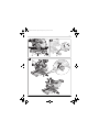
1
OBJ_BUCH-1130-001.book Page 44 Monday, January 18, 2010 10:33 AM
44 | English
Adjusting Vertical Bevel Angles
To ensure precise cuts, the basic adjustment of
the machine must be checked and adjusted as
necessary after intensive use (see “Checking
and Adjusting the Basic Adjustment”, page 49).
The vertical bevel angle can be adjusted in a
range from 47° (leftward) to 47° (rightward).
For quick and precise adjustment of commonly
used bevel angles, stops are provided for 0°,
45° and 33.9° angles.
Bevel angle range 45°– 0
– Pull the left fence extension 21 completely
outward. (see “Extending the Fence”,
page 43)
– Loosen the clamping lever 16.
– Tilt the tool arm leftward via handle 7 until
the angle indicator 33 indicates the desired
bevel angle.
– Hold the tool arm in this position and retighten the clamping lever 16.
The clamping force of the clamping lever
must securely hold the position of the tool
arm at any bevel angle.
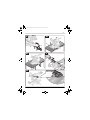
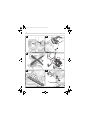
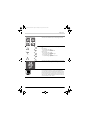
Bevel angle range 0 – 45° (see figure K)
– Pull the right fence extension 21 completely
outward. (see “Extending the Fence”,
page 43)
– Loosen the clamping lever 16.
– Lightly tilt the tool arm leftward out of the 0°
position via handle 7 and turn knob 41 until
the desired bevel angle range is indicated.
– Tilt the tool arm via handle 7 to the right until
angle indicator 24 indicates the desired bevel angle.
– Hold the tool arm in this position and retighten the clamping lever 16.
The clamping force of the clamping lever
must securely hold the position of the tool
arm at any bevel angle.
1 609 929 W13 | (18/1/10)
Standard 0° Bevel Angle
To enable simple and swift resetting of the
standard 0° bevel angle, knob 41 will engage in
the 45°– 0 bevel angle range.
– Tilt the tool arm from right to left over the 0°
position.
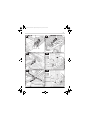
Bevel angle range 45°+
– Pull both fence extensions 21 completely
outward. (see “Extending the Fence”,
page 43)
– Loosen the clamping lever 16.
– Lightly tilt the tool arm leftward out of the 0°
position via handle 7 and turn knob 41 until
the desired bevel angle range is indicated.
– Tilt the tool arm via handle 7 to the left or
right until angle indicator 33 or 24 indicate
the desired bevel angle.
– Hold the tool arm in this position and retighten the clamping lever 16.
The clamping force of the clamping lever
must securely hold the position of the tool
arm at any bevel angle.
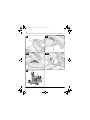
Standard 33.9° Bevel Angle
– Pull adjustment knob 34 completely outward
and turn it by 90°. Now tilt the tool arm via
the handle 7 until the tool arm can be heard
to engage.
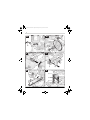
Adjusting the Handle (see figure L)
For a more convenient hand position, the handle
7 can be turned to 4 different positions.
– Loosen clamp 5.
– Grasp and pull tongue 6 outward, then turn
handle 7 until it engages in the desired position.
– Let go of tongue 6 again and lock clamp 5.
Bosch Power Tools