1
AnadigmApex
Development Board Quick Start Guide
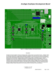
KEY FEATURE LOCATIONS ON THE ANADIGMAPEX DEVELOPMENT BOARD
Config OK LED (Green)
Config FAIL LED (Red)
Analog Signal
I/O headers
Serial RS232
Supply Jack
Supply screw
terminal
Power OK LED
Reset button
STEP 1: CHECK THE CONTENTS OF YOUR KIT
•
•
•
•
•
•
AnadigmApex Development Board
Serial Interface Cable (RS-232)
AnadigmApex Development Board Quick Start Guide
A231D04E AnadigmApex Development Board User Manual
AN231E04 Field Programmable Analog Array User Manual
Software/Documentation CD-ROM
STEP 2: SOFTWARE INSTALLATION
•
•
•
•
•
•
If you do not already have Anadigmdesigner2 on you PC. Insert the software/documentation
CD-ROM into your PC’s CD-ROM drive. The software should automatically prompt you for
installation. (Note: Anadigm’s web site has the most up to date version of the software.
After you have installed the software, you will need to register your copy of the software with
Anadigm® online at http://www.anadigm.com/sup_downloadcenter.asp?tab=ad2
For registration you will need first to create a MyAnadigm account, then follow the web site
instructions to licence your software – (please use your real email address)
Once you have registered online, a license ID and a license key will be e-mailed to you.
Please enter these in the registration dialog box of the AnadigmDesigner®2 software.
You are now ready to use the world’s first FPAA design software!
AnadigmApex
Development Board Quick Start Guide
STEP 3: CONNECT THE DEVELOPMENT BOARD
•
•
Using the RS-232 serial interface cable, connect the development board to your PC’s serial
port.
Connect a suitable power supply to the evaluation board. The board is designed to accept the
following types of connectors and supply voltages:
1. Connect a regulated lab supply to the on-board 2-way screw terminal: negative post at
0volts, positive post between +4.5 V to +9 V
OR
2. Use an AC wall converter (regulated) and connect into the supply jack, +4.5 V minimum,
+12 V maximum. The center pole of the supply jack is positive.
Anadigm recommends a +9v regulated supply be connected to the Jack socket.
Note: Do not use the 2-way screw terminal and the AC wall supply jack concurrently.
STEP 4: APPLY POWER
•
When the board is powered up properly, the Power OK LED will illuminate green.
STEP 5: YOU ARE NOW READY TO USE YOUR AnadigmApex DEVELOPMENT BOARD
•
•
•
Configure the FPAA from AnadigmDesigner®2 with a suitable circuit.
Analog signal connections are available at the Analog Signal I/O Headers.
Refer to your AN231D04E AnadigmApex Development Board User Manual.
This document is for use in conjunction with Anadigm® software which is subject to the terms of an Anadigm® software license. This
document does not form part of any contract or specification between Anadigm® and the user and is for guidance and illustration only.
Accordingly, we accept no liability arising out of the use of the document in conjunction with the software to the extent permitted by law.
For more information logon to:
www.anadigm.com
or e-mail
[email protected]
Copyright © 2005 Anadigm, Inc., All Rights Reserved
QS231001-0001a