1
Cat. No. I524-E1-2
USER’S MANUAL
OMNUC FND-X
SERIES
MODELS FND-Xj (DIO Type)
FND-Xj-SRT (CompoBus/S Type)
POSITION DRIVERS
Thank you for choosing this OMNUC FND-X-series product.
This manual provides details on the installation, wiring, troubleshooting, and maintenance of
OMNUC FND-X-series products along with parameter settings for the operation of the products.
S Make sure that actual users of this product will read this manual thoroughly and handle and operate the product with care.
S Retain this manual for future reference.
S This manual describes the specifications and functions of the product and relations with other products. Assume that nothing described in this manual is possible.
S Specifications and functions may change without notice to improve product performance.
S Forward and reverse rotation of AC Servomotors described in this manual are defined as looking at the end of
the output shaft of the motor as follows: counterclockwise rotation is forward and clockwise rotation is reverse.
General Instructions
1. Refer to Precautions first and carefully read and be sure to understand the information provided.
2. Familiarize yourself with this manual and understand the functions and performance of the Servomotor and Servo Driver for proper use.
3. The Servomotor and Servo Driver must be wired and operated by experts in electrical engineering.
4. We recommend that you add the following precautions to any instruction manuals you prepare for
the system into which the product is being installed.
S Precautions on the dangers of high-voltage equipment.
S Precautions on touching the terminals of the product even after power has been turned OFF.
(These terminals are live even with the power turned OFF.)
5. Do not perform withstand voltage or other megameter tests on the product. Doing so may damage
internal components.
6. Servomotors and Servo Drivers have a finite service life. Be sure to keep replacement products on
hand and to consider the operating environment and other conditions affecting the service life.
7. Do not set any parameter not described in this manual, otherwise the Servomotor or Servo Driver
may malfunction. Contact your OMRON representatives if you have any inquiry.
NOTICE
Before using the product under the following conditions, consult your OMRON representatives, make
sure that the ratings and performance characteristics of the product are good enough for the systems,
machines, or equipment, and be sure to provide the systems, machines, or equipment with double safety
mechanisms.
1. Conditions not described in the manual.
2. The application of the product to nuclear control systems, railroad systems, aviation systems, vehicles, combustion systems, medical equipment, amusement machines, or safety equipment.
3. The application of the product to systems, machines, or equipment that may have a serious influence
on human life and property if they are used improperly.
Items to Check After Unpacking
Check the following items after removing the product from the package:
S Has the correct product been delivered (i.e., the correct model number and specifications)?
S Has the product been damaged in shipping?
The product is provided with Safety Precautions Sheets. No connectors or mounting screws are
provided.
Notice:
OMRON products are manufactured for use according to proper procedures by a qualified
operator and only for the purposes described in this manual.
The following conventions are used to indicate and classify precautions in this manual. Always heed the information provided with them. Failure to heed precautions can result in injury to people or damage to property.
!
DANGER
Indicates an imminently hazardous situation which, if not avoided, will result in death
or serious injury.
!
WARNING
Indicates a potentially hazardous situation which, if not avoided, could result in death
or serious injury.
! Caution
Indicates a potentially hazardous situation which, if not avoided, may result in minor
or moderate injury, or property damage.
OMRON Product References
All OMRON products are capitalized in this manual. The word “Unit” is also capitalized when
it refers to an OMRON product, regardless of whether or not it appears in the proper name
of the product.
The abbreviation “Ch,” which appears in some displays and on some OMRON products,
often means “word” and is abbreviated “Wd” in documentation in this sense.
The abbreviation “PC” means Programmable Controller and is not used as an abbreviation
for anything else.
Visual Aids
The following headings appear in the left column of the manual to help you locate different
types of information.
Note Indicates information of particular interest for efficient and convenient operation of the product.
OMRON, 1998
All rights reserved. No part of this publication may be reproduced, stored in a retrieval system, or transmitted,
in any form, or by any means, mechanical, electronic, photocopying, recording, or otherwise, without the prior
written permission of OMRON.
No patent liability is assumed with respect to the use of the information contained herein. Moreover, because
OMRON is constantly striving to improve its high-quality products, the information contained in this manual
is subject to change without notice. Every precaution has been taken in the preparation of this manual. Nevertheless, OMRON assumes no responsibility for errors or omissions. Neither is any liability assumed for damages resulting from the use of the information contained in this publication.
General Precautions
Observe the following precautions when using the OMNUC Position Drivers and peripheral
devices.
This manual may include illustrations of the product with protective covers removed in order
to describe the components of the product in detail. Make sure that these protective covers
are on the product before use.
Consult your OMRON representative when using the product after a long period of storage.
!
WARNING
Do not touch the inside of the Servo Driver. Doing so may result in electric shock.
!
WARNING
Always connect the frame ground terminals of the Servo Driver and the Servomotor
to a class-3 ground (to 100 Ω or less). Not connecting to a class-3 ground may result
in electric shock.
!
WARNING
Do not remove the front cover, terminal covers, cables, Parameter Units, or optional
items while the power is being supplied. Doing so may result in electric shock.
!
WARNING
Operation, maintenance, or inspection must be performed by authorized personnel.
Not doing so may result in operation stoppage, burning of the product, electric
shock, or injury.
!
WARNING
Wiring or inspection must be performed at least 1 minute after turning off the power
supply. Doing so may result in electric shock.
!
WARNING
Do not damage, pull on, apply stress to, place heavy objects on, or pinch the cables.
Doing so may result in electric shock.
!
WARNING
Do not touch the rotating parts of the Servomotor under operation. Doing so may
result in injury.
!
WARNING
Do not modify the product. Doing so may result in injury or damage to the product.
! Caution
Use the Servomotors and Servo Drivers in a specified combination. Not doing so
may result in fire or damage to the products.
! Caution
Do not store or install the product in the following places. Doing so may result in electric shock, fire or damage to the product.
S Locations subject to direct sunlight.
S Locations subject to temperatures or humidity outside the range specified in the
specifications.
S Locations subject to condensation as the result of severe changes in temperature.
S Locations subject to corrosive or flammable gases.
S Locations subject to dust (especially iron dust) or salts.
S Locations subject to shock or vibration.
S Locations subject to exposure to water, oil, or chemicals.
! Caution
Do not touch the Servo Driver radiator, regenerative resistor, or Servomotor while
the power is being supplied or soon after the power is turned off. Doing so may result
in a skin burn due to the hot surface.
Storage and Transportation Precautions
! Caution
Do not hold by the cables or motor shaft while transporting the product. Doing so
may result in injury or malfunction.
! Caution
Do not place any load exceeding the figure indicated on the product. Doing so may
result in injury or malfunction.
! Caution
Use the motor eye-bolts only for transporting the Servomotor. Using them for transporting the machinery may result in injury or malfunction.
Installation and Wiring Precautions
! Caution
Do not step on or place a heavy object on the product. Doing so may result in injury.
! Caution
Do not cover the inlet or outlet ports and prevent any foreign objects from entering
the product. Doing so may result in fire.
! Caution
Be sure to install the product in the correct direction. Not doing so may result in malfunction.
! Caution
Provide the specified clearances between the Servo Driver and the control panel or
with other devices. Not doing so may result in fire or malfunction.
! Caution
Do not apply any strong impact. Doing so may result in malfunction.
! Caution
Be sure to wire correctly and securely. Not doing so may result in motor runaway,
injury, or malfunction.
! Caution
Be sure to firmly tighten the screws fixing the product, the terminal block, and cables.
Not doing so may result in malfunction.
! Caution
Use crimp terminals for wiring. Do not connect bare stranded wires directly to the
terminal block. Doing so may result in fire.
! Caution
Use the power supply voltages specified in this manual. Not doing so may result in
burning.
! Caution
Take appropriate measures to ensure that the specified power with the rated voltage
is supplied. Be particularly careful in places where the power supply is unstable. Not
doing so may result in damage to the product.
! Caution
Install external breakers and take other safety measures against short-circuiting in
external wiring. Not doing so may result in fire.
! Caution
Provide an appropriate stopping device on the machine side to secure safety. (A
holding brake is not a stopping device for securing safety.) Not doing so may result in
injury.
! Caution
Provide an external emergency stopping device that allows an instantaneous stop of
operation and power interruption. Not doing so may result in injury.
! Caution
Take appropriate and sufficient countermeasures when installing systems in the following locations. Not doing so may result in equipment damage.
S Locations subject to static electricity or other forms of noise.
S Locations subject to strong electromagnetic fields and magnetic fields.
S Locations subject to possible exposure to radioactivity.
S Locations close to power supplies.
Operation and Adjustment Precautions
! Caution
Confirm that no adverse effect will occur in the system before performing the test
operation. Not doing so may result in equipment damage.
! Caution
Check the newly set parameters for proper execution before actually running them.
Not doing so may result in equipment damage.
! Caution
Do not make any extreme adjustments or setting changes. Doing so may result in
unstable operation and injury.
! Caution
Separate the Servomotor from the machine, check for proper operation, and then
connect to the machine. Not doing so may cause injury.
! Caution
When an alarm occurs, remove the cause, reset the alarm after confirming safety,
and then resume operation. Not doing so may result in injury.
! Caution
Do not come close to the machine immediately after resetting momentary power interruption to avoid an unexpected restart. (Take appropriate measures to secure
safety against an unexpected restart.) Doing so may result in injury.
! Caution
Do not use the built-in brake of the Servomotor for ordinary braking. Doing so may
result in malfunction.
Maintenance and Inspection Precautions
!
WARNING
! Caution
Do not attempt to take the Unit apart or repair. Doing either of these may result in
electrical shock or injury.
Resume operation only after transferring to the new Unit the contents of the data required for operation. Not doing so may result in equipment damage.
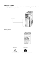
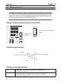
Warning Labels
Warning labels are pasted on the product as shown in the following illustration. Be sure to
follow the instructions given there.
Warning labels
Warning Labels
Warning label 1
May cause electric shock.
Warning label 2
Connect to a ground of 100 Ω or less.
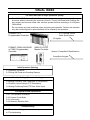
VISUAL INDEX
For users who wish to begin operations quickly.
- The OMNUC FND-X-series Position Driver allows motor test operation only by wiring the driver
and motor without connecting the controller. Read 3-2 Turning ON Power and Checking Display, properly set the motor model code, and then operate the motor according to 3-8-2 System
Check Mode.
Do not connect any load (machines) when performing test operation. Perform test operation
only after confirming that no adverse effects will be caused by test operation.
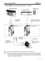
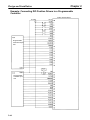
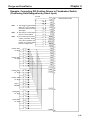
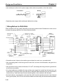
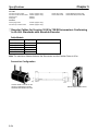
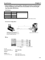
5-3-1 General Control
Cable Specifications
SYSMAC C/CV
Programmable Controller
I/O signals
SYSMAC C200H-HX/HG/HE
or CQM1 Programmable
Controller
SRM1-C01/-C02
Master Controller
Section 6 CompoBus/S Specifications
CompoBus/S signals
Initial Operation (Starting)
- 3-1 Operation Procedure
- 3-2Turning ON Power and Checking Displays
Function Settings (Parameter Settings)
- 3-4 Setting Functions: User Parameters (H Parameters)
- 3-5 Position Control Settings (PTP Parameters)
- 3-6 Setting Positioning Data (PTP Data, Direct Input)
Trial Operation and Adjustments
- 3-8-1 Trial Operation Procedure
- 3-8-2 System Check Mode
- 3-9-1 Auto-tuning
- 3-9-2 Manually Adjusting Gain
Troubleshooting
- 4-4 Protection and Diagnosis
- 4-5 Troubleshooting
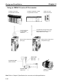
OMNUC FND-X Series
Teaching Box
CVM1-PRO01 Teaching Box
ROM Cassette:
CVM1-MP702
(Common for MC Units and
Position Drivers)
CVM1-MP703
For details refer to Cat. No. W354-E1.
RS-422 Teaching Box connections cable
OMNUC FND-X-series Position Drivers
5-1 Position Driver Specifications
2-2-3 Wiring Terminal Blocks
3-3-3 Mode Details
6-3 Connecting a CompoBus/S
System
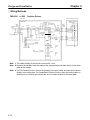
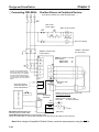
2-2-2 Control Circuitry
Terminal Wiring
CompoBus/S Type
200 V: FND-XjjH-SRT
100 V: FND-XjjL-SRT
DIO Type
200 V: FND-XjjH
100 V: FND-XjjL
5-3 Cable Specifications
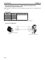
Power signals
OMNUC M-series
AC Servomotors
1200 r/min: 200 to 1.8 kW with Resolver
2000 r/min: 200 to 2.2 kW with Resolver
4000 r/min: 60 to 2 kW with Resolver
Encoder/Resolver signals
OMNUC U-series
AC Servomotors
OMNUC U-UE-series
AC Servomotors
OMNUC H-series
AC Servomotors
3000 r/min: 30 to 2 kW with
Incremental Encoder
3000 r/min: 30 to 2 kW with
Absolute Encoder
3000 r/min: 100 to 750 W with
Incremental Encoder
3000 r/min: 50 to 1100 W with
Incremental Encoder
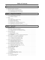
Table of Contents
Chapter 1. Introduction . . . . . . . . . . . . . . . . . . . . . . . . . . . . . . . . . . . . .
1-1 Functions . . . . . . . . . . . . . . . . . . . . . . . . . . . . . . . . . . . . . . . . . . . . . . . . . . . . . . . . . . . . . . . . . .
1-2 Nomenclature and Key Operations . . . . . . . . . . . . . . . . . . . . . . . . . . . . . . . . . . . . . . . . . . . . . .
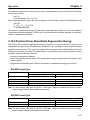
1-3 Supported Standards and Supporting Models . . . . . . . . . . . . . . . . . . . . . . . . . . . . . . . . . . . . . .
1-3-1 Standards Supported by Position Drivers . . . . . . . . . . . . . . . . . . . . . . . . . . . . . . . . . . .
1-3-2 Standards Supported by AC Servomotors . . . . . . . . . . . . . . . . . . . . . . . . . . . . . . . . . .
Chapter 2. Design and Installation . . . . . . . . . . . . . . . . . . . . . . . . . . . .
2-1 Installation . . . . . . . . . . . . . . . . . . . . . . . . . . . . . . . . . . . . . . . . . . . . . . . . . . . . . . . . . . . . . . . . .
2-1-1 External Dimensions (Unit: mm) . . . . . . . . . . . . . . . . . . . . . . . . . . . . . . . . . . . . . . . . .
2-1-2 Installation Conditions . . . . . . . . . . . . . . . . . . . . . . . . . . . . . . . . . . . . . . . . . . . . . . . . .
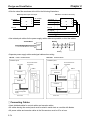
2-2 Wiring . . . . . . . . . . . . . . . . . . . . . . . . . . . . . . . . . . . . . . . . . . . . . . . . . . . . . . . . . . . . . . . . . . . .
2-2-1 Overview . . . . . . . . . . . . . . . . . . . . . . . . . . . . . . . . . . . . . . . . . . . . . . . . . . . . . . . . . . . .
2-2-2 Control Circuitry Terminal Wiring . . . . . . . . . . . . . . . . . . . . . . . . . . . . . . . . . . . . . . . .
2-2-3 Wiring Terminal Blocks . . . . . . . . . . . . . . . . . . . . . . . . . . . . . . . . . . . . . . . . . . . . . . . .
2-2-4 Wiring for Noise Resistance . . . . . . . . . . . . . . . . . . . . . . . . . . . . . . . . . . . . . . . . . . . . .
2-2-5 Wiring Products Conforming to EMC Directives . . . . . . . . . . . . . . . . . . . . . . . . . . . .
2-2-6 Peripheral Device Connection Examples . . . . . . . . . . . . . . . . . . . . . . . . . . . . . . . . . . .
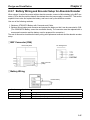
2-2-7 Battery Wiring and Encoder Setup for Absolute Encoder . . . . . . . . . . . . . . . . . . . . . .
Chapter 3. Operation . . . . . . . . . . . . . . . . . . . . . . . . . . . . . . . . . . . . . . .
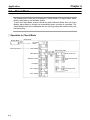
3-1 Operational Procedure . . . . . . . . . . . . . . . . . . . . . . . . . . . . . . . . . . . . . . . . . . . . . . . . . . . . . . . .
3-2 Turning ON Power and Checking Displays . . . . . . . . . . . . . . . . . . . . . . . . . . . . . . . . . . . . . . .
3-2-1 Items to Check Before Turning ON the Power . . . . . . . . . . . . . . . . . . . . . . . . . . . . . .
3-2-2 Turning ON the Power and Checking the Display . . . . . . . . . . . . . . . . . . . . . . . . . . . .
3-3 Using the Display Area . . . . . . . . . . . . . . . . . . . . . . . . . . . . . . . . . . . . . . . . . . . . . . . . . . . . . . .
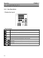
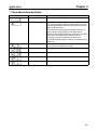
3-3-1 Key Operations . . . . . . . . . . . . . . . . . . . . . . . . . . . . . . . . . . . . . . . . . . . . . . . . . . . . . . .
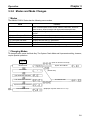
3-3-2 Modes and Mode Changes . . . . . . . . . . . . . . . . . . . . . . . . . . . . . . . . . . . . . . . . . . . . . .
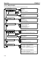
3-3-3 Mode Details . . . . . . . . . . . . . . . . . . . . . . . . . . . . . . . . . . . . . . . . . . . . . . . . . . . . . . . . .
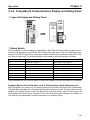
3-3-4 CompoBus/S Communications Display and Setting Panel . . . . . . . . . . . . . . . . . . . . .
3-4 Setting Functions: User Parameters (H Parameters) . . . . . . . . . . . . . . . . . . . . . . . . . . . . . . . . .
3-4-1 Setting User Parameters and H Parameters . . . . . . . . . . . . . . . . . . . . . . . . . . . . . . . . .
3-4-2 User Parameter and H Parameter Tables . . . . . . . . . . . . . . . . . . . . . . . . . . . . . . . . . . .
3-4-3 User Parameter and H Parameter Details . . . . . . . . . . . . . . . . . . . . . . . . . . . . . . . . . . .
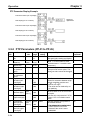
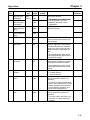
3-5 Position Control Settings (PTP Parameters) . . . . . . . . . . . . . . . . . . . . . . . . . . . . . . . . . . . . . . .
3-5-1 Setting PTP Parameters (PP-01 to PP-26) . . . . . . . . . . . . . . . . . . . . . . . . . . . . . . . . . .
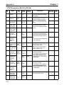
3-5-2 PTP Parameters (PP-01 to PP-26) . . . . . . . . . . . . . . . . . . . . . . . . . . . . . . . . . . . . . . . .
3-5-3 PTP Parameter Details (PP-01 to PP-26) . . . . . . . . . . . . . . . . . . . . . . . . . . . . . . . . . . .
3-6 Setting Positioning Data (PTP Data, Direct Input) . . . . . . . . . . . . . . . . . . . . . . . . . . . . . . . . . .
3-6-1 Setting PTP Data (When UP-01 is 11 or 12) . . . . . . . . . . . . . . . . . . . . . . . . . . . . . . . .
3-6-2 Setting Direct Input (When UP-01 is 13 or 14) . . . . . . . . . . . . . . . . . . . . . . . . . . . . . .
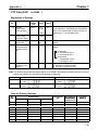
3-6-3 PTP Data (Pd01jj to Pd64j) . . . . . . . . . . . . . . . . . . . . . . . . . . . . . . . . . . . . . . . . . . . . .
3-6-4 PTP Data Details (Pdjjj) . . . . . . . . . . . . . . . . . . . . . . . . . . . . . . . . . . . . . . . . . . . . . . . .
3-7 Operational Sequence . . . . . . . . . . . . . . . . . . . . . . . . . . . . . . . . . . . . . . . . . . . . . . . . . . . . . . . .
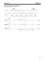
3-7-1 Origin Search . . . . . . . . . . . . . . . . . . . . . . . . . . . . . . . . . . . . . . . . . . . . . . . . . . . . . . . .
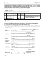
3-7-2 Origin Teaching . . . . . . . . . . . . . . . . . . . . . . . . . . . . . . . . . . . . . . . . . . . . . . . . . . . . . .
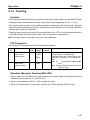
3-7-3 Teaching . . . . . . . . . . . . . . . . . . . . . . . . . . . . . . . . . . . . . . . . . . . . . . . . . . . . . . . . . . . .
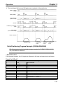
3-7-4 Point Positioning (UP-01: 11 or 12) . . . . . . . . . . . . . . . . . . . . . . . . . . . . . . . . . . . . . . .
3-7-5 Direct Positioning (UP-01: 13 or 14) . . . . . . . . . . . . . . . . . . . . . . . . . . . . . . . . . . . . . .
3-8 Trial Operation . . . . . . . . . . . . . . . . . . . . . . . . . . . . . . . . . . . . . . . . . . . . . . . . . . . . . . . . . . . . . .
3-8-1 Trial Operation Procedure . . . . . . . . . . . . . . . . . . . . . . . . . . . . . . . . . . . . . . . . . . . . . .
3-8-2 System Check Mode . . . . . . . . . . . . . . . . . . . . . . . . . . . . . . . . . . . . . . . . . . . . . . . . . . .
Table of Contents
3-9 Making Adjustments . . . . . . . . . . . . . . . . . . . . . . . . . . . . . . . . . . . . . . . . . . . . . . . . . . . . . . . . .
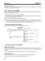
3-9-1 Auto-tuning . . . . . . . . . . . . . . . . . . . . . . . . . . . . . . . . . . . . . . . . . . . . . . . . . . . . . . . . . .
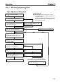
3-9-2 Manually Adjusting Gain . . . . . . . . . . . . . . . . . . . . . . . . . . . . . . . . . . . . . . . . . . . . . . .
3-9-3 Adjustment Parameter Details . . . . . . . . . . . . . . . . . . . . . . . . . . . . . . . . . . . . . . . . . . .
3-10 Regenerative Energy Absorption . . . . . . . . . . . . . . . . . . . . . . . . . . . . . . . . . . . . . . . . . . . . . . . .
3-10-1 Calculating Regenerative Energy . . . . . . . . . . . . . . . . . . . . . . . . . . . . . . . . . . . . . . . . .
3-10-2 Position Driver Absorbable Regenerative Energy . . . . . . . . . . . . . . . . . . . . . . . . . . . .
3-10-3 Regenerative Energy Absorption by Regeneration Resistor . . . . . . . . . . . . . . . . . . . .
Chapter 4. Application . . . . . . . . . . . . . . . . . . . . . . . . . . . . . . . . . . . . . .
4-1 Monitor Mode . . . . . . . . . . . . . . . . . . . . . . . . . . . . . . . . . . . . . . . . . . . . . . . . . . . . . . . . . . . . . .
4-2 Check Mode . . . . . . . . . . . . . . . . . . . . . . . . . . . . . . . . . . . . . . . . . . . . . . . . . . . . . . . . . . . . . . . .
4-2-1 I/O Signal Status . . . . . . . . . . . . . . . . . . . . . . . . . . . . . . . . . . . . . . . . . . . . . . . . . . . . . .
4-3 Monitor Output . . . . . . . . . . . . . . . . . . . . . . . . . . . . . . . . . . . . . . . . . . . . . . . . . . . . . . . . . . . . .
4-4 Protection and Diagnosis . . . . . . . . . . . . . . . . . . . . . . . . . . . . . . . . . . . . . . . . . . . . . . . . . . . . . .
4-4-1 Alarms . . . . . . . . . . . . . . . . . . . . . . . . . . . . . . . . . . . . . . . . . . . . . . . . . . . . . . . . . . . . . .
4-4-2 Countermeasures to Alarms . . . . . . . . . . . . . . . . . . . . . . . . . . . . . . . . . . . . . . . . . . . . .
4-4-3 CompoBus/S-type Position Driver Protective and Diagnostic Functions . . . . . . . . . .
4-4-4 Overload Characteristics . . . . . . . . . . . . . . . . . . . . . . . . . . . . . . . . . . . . . . . . . . . . . . . .
4-4-5 Alarm Output . . . . . . . . . . . . . . . . . . . . . . . . . . . . . . . . . . . . . . . . . . . . . . . . . . . . . . . .
4-5 Troubleshooting . . . . . . . . . . . . . . . . . . . . . . . . . . . . . . . . . . . . . . . . . . . . . . . . . . . . . . . . . . . . .
4-5-1 Preliminary Inspection . . . . . . . . . . . . . . . . . . . . . . . . . . . . . . . . . . . . . . . . . . . . . . . . .
4-5-2 Precautions . . . . . . . . . . . . . . . . . . . . . . . . . . . . . . . . . . . . . . . . . . . . . . . . . . . . . . . . . .
4-5-3 Replacing the Position Driver and the Motor . . . . . . . . . . . . . . . . . . . . . . . . . . . . . . . .
4-5-4 Troubleshooting . . . . . . . . . . . . . . . . . . . . . . . . . . . . . . . . . . . . . . . . . . . . . . . . . . . . . .
4-6 Periodic Maintenance . . . . . . . . . . . . . . . . . . . . . . . . . . . . . . . . . . . . . . . . . . . . . . . . . . . . . . . .
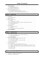
Chapter 5. Specifications . . . . . . . . . . . . . . . . . . . . . . . . . . . . . . . . . . . .
5-1 Position Driver Specifications . . . . . . . . . . . . . . . . . . . . . . . . . . . . . . . . . . . . . . . . . . . . . . . . . .
5-1-1 General Specifications (Common to DIO, CompoBus/S) . . . . . . . . . . . . . . . . . . . . . .
5-1-2 Performance Specifications . . . . . . . . . . . . . . . . . . . . . . . . . . . . . . . . . . . . . . . . . . . . .
5-1-3 I/O Specifications . . . . . . . . . . . . . . . . . . . . . . . . . . . . . . . . . . . . . . . . . . . . . . . . . . . . .
5-2 Servomotor Specifications . . . . . . . . . . . . . . . . . . . . . . . . . . . . . . . . . . . . . . . . . . . . . . . . . . . . .
5-2-1 U-series 30-W to 750-W Servomotors (INC/ABS) . . . . . . . . . . . . . . . . . . . . . . . . . . .
5-2-2 U-UE-series Servomotors . . . . . . . . . . . . . . . . . . . . . . . . . . . . . . . . . . . . . . . . . . . . . . .
5-2-3 U-series 1-kW to 2-kW Servomotors (INC/ABS) . . . . . . . . . . . . . . . . . . . . . . . . . . . .
5-2-4 H-series Servomotors . . . . . . . . . . . . . . . . . . . . . . . . . . . . . . . . . . . . . . . . . . . . . . . . . .
5-2-5 M-series Servomotors . . . . . . . . . . . . . . . . . . . . . . . . . . . . . . . . . . . . . . . . . . . . . . . . . .
5-3 Cable Specifications . . . . . . . . . . . . . . . . . . . . . . . . . . . . . . . . . . . . . . . . . . . . . . . . . . . . . . . . .
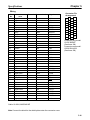
5-3-1 General Control Cables (DIO Position Drivers Only) . . . . . . . . . . . . . . . . . . . . . . . . .
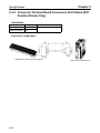
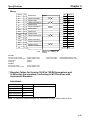
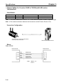
5-3-2 Connector Terminal Board Conversion Unit Cables (DIO Position Drivers Only) . . .
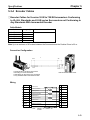
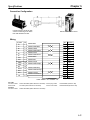
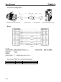
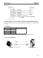
5-3-3 External Control Signal Connecting Cables (CompoBus/S Position Drivers Only) . .
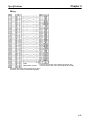
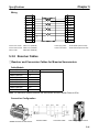
5-3-4 Encoder Cables . . . . . . . . . . . . . . . . . . . . . . . . . . . . . . . . . . . . . . . . . . . . . . . . . . . . . . .
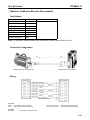
5-3-5 Resolver Cables . . . . . . . . . . . . . . . . . . . . . . . . . . . . . . . . . . . . . . . . . . . . . . . . . . . . . .
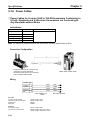
5-3-6 Power Cables . . . . . . . . . . . . . . . . . . . . . . . . . . . . . . . . . . . . . . . . . . . . . . . . . . . . . . . .
Chapter 6. CompoBus/S Specifications . . . . . . . . . . . . . . . . . . . . . . . . .
6-1 CompoBus/S Configuration Requirements . . . . . . . . . . . . . . . . . . . . . . . . . . . . . . . . . . . . . . . .
6-2 CompoBus/S Communications Specifications . . . . . . . . . . . . . . . . . . . . . . . . . . . . . . . . . . . . .
6-3 Connecting a CompoBus/S System . . . . . . . . . . . . . . . . . . . . . . . . . . . . . . . . . . . . . . . . . . . . . .
Table of Contents
Chapter 7. Appendices . . . . . . . . . . . . . . . . . . . . . . . . . . . . . . . . . . . . . .
7-1 Standard Models . . . . . . . . . . . . . . . . . . . . . . . . . . . . . . . . . . . . . . . . . . . . . . . . . . . . . . . . . . . .
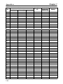
7-2 Parameter Settings Tables . . . . . . . . . . . . . . . . . . . . . . . . . . . . . . . . . . . . . . . . . . . . . . . . . . . . .
Revision History . . . . . . . . . . . . . . . . . . . . . . . . . . . . . . . . .
1
Chapter 1
Introduction
1-1
1-2
1-3
Functions
Nomenclature and Key Operations
Supported Standards and Supporting Models
Chapter 1
Introduction
1-1
Functions
OMRON’s FND-X Position Drivers are servo drivers with built-in positioner functions
that control AC servomotors according to positioning data.
j FND-X-Series Models
There are two types of FND-X Position Drivers, according to the type of control signals used.
Control signals
DIO
CompoBus/S
Model
FND-XH/FND-XL
FND-XH-SRT/FND-XL-SRT
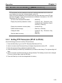
Up to eight CompoBus/S Position Drivers can be connected to one Master Unit for 128 input and 128
output points. Two-wire communications are used, reducing system wiring. High-speed communications are also achieved, with a communications cycle time of 0.5 or 0.8 ms.
Note Only the high-speed communications mode is available with the FND-X.
j International Standards: EC Directives and UL/cUL Standards
Position Drivers manufactured beginning April 1999 are available that conform to EC directives and
UL/cUL standards, making it easier to conform to these standards in the overall system. When conforming to directives/standards, use U-series Servomotors that also conform to the require directives/standards.
j Applicable Servomotor Models
The following AC Servomotors can be connected to FND-X-series Position Drivers.
• OMNUC U Series (30 to 750 W)
Servomotors Conforming to UL/cUL Standards
With incremental encoders: R88M-UHA-
With absolute encoders:
R88M-UTA-
Servomotors Conforming to EC Directives
With incremental encoders: R88M-UVA-
With absolute encoder:
R88M-UXA-
• OMNUC U Series (1 to 2 kW)
Servomotors Not Conforming to Standards
With incremental encoder: R88M-UH-
With absolute encoder:
R88M-UT-
Servomotors Conforming to EC Directives
With incremental encoder: R88M-UV-
With absolute encoder:
R88M-UX-
• OMNUC U-UE Series (100 to 750 W)
Servomotors Not Conforming to Standards
With incremental encoder: R88M-UEH-
Servomotors Conforming to EC Directives
With incremental encoder: R88M-UEV-
1-2
Chapter 1
Introduction
• OMNUC H (50 to 1,100 W) Series (with incremental encoder):
R88M-H-
• OMNUC M (60 to 2,200 W) Series (with resolver):
R88M-M-
Note H-series and M-series models do not conform to the EC Directives and UL/cUL standards.
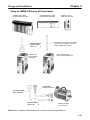
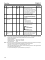
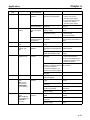
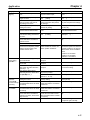
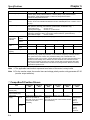
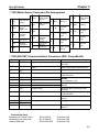
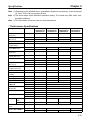
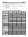
• The following models are available with different output capacities, and are arranged according to input power supply.
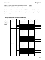
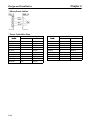
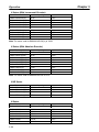
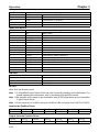
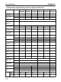
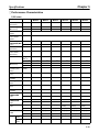
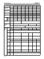
D Position Driver and AC Servomotor Combinations
Position Driver
Input power
Model
supply
Single-phase
g
FND-X06H-
200/240
/
((170 to
264) VAC at
50/60 Hz
FND-X12H-
FND-X25H-
Applicable AC Servomotor
Series
Model
Output
capacity
U
R88M-U03030A
30 W
R88M-U05030A
50 W
R88M-U10030A
100 W
U-UE
R88M-UE10030-S1
100 W
H
R88M-H05030
50 W
R88M-H10030
100 W
U
R88M-U20030A
200 W
R88M-U40030A
400 W
U-UE
R88M-UE20030-S1
200 W
R88M-UE40030-S1
400 W
H
R88M-H20030
200 W
R88M-H30030
300 W
M
R88M-M06040
60 W
R88M-M12040
120 W
R88M-M20040
200 W
R88M-M40040
400 W
R88M-M20020
200 W
R88M-M40020
400 W
R88M-M20012
200 W
R88M-M40012
400 W
U
R88M-U75030A
750 W
R88M-U1K030
1000 W
U-UE
R88M-UE75030-S1
750 W
H
R88M-H50030
500 W
R88M-H75030
750 W
R88M-H1K130
1100 W
M
R88M-M70040
700 W
R88M-M1K140
1100 W
R88M-M70020
700 W
R88M-M1K120
1100 W
R88M-M70012
700 W
Rated r/min
3,000
,
r/min
3,000 r/min
3,000
,
r/min
3,000
,
r/min
3,000
r/min
,
3,000
,
r/min
4,000
,
r/min
2,000
,
r/min
1,200
,
r/min
3,000
,
r/min
3,000 r/min
3,000
,
r/min
4,000
,
r/min
2,000
,
r/min
1,200 r/min
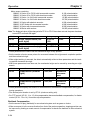
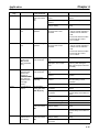
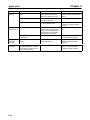
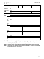
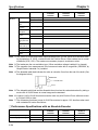
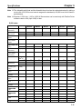
1-3
Chapter 1
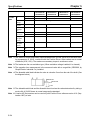
Introduction
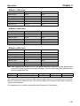
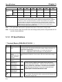
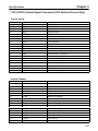
Position Driver
Input power
Model
supply
Three-phase
FND-X50H-
(1 0 to
200/240 (170
264) VAC at
50/60 Hz
Single-phase
g
100/115
/
((85 to
127) VAC at
50/60 Hz
FND-X06L-
FND-X12L-
Applicable AC Servomotor
Series
Model
Output
capacity
U
R88M-U1K530
1500 W
R88M-U2K030
2000 W
M
R88M-M2K040
2000 W
R88M-M1K820
1800 W
R88M-M2K220
2200 W
R88M-M1K112
1100 W
R88M-M1K412
1400 W
R88M-M1K812
1800 W
U
R88M-U03030A
30 W
R88M-U05030A
50 W
R88M-U10030A
100 W
U-UE
R88M-UE10030-S1
100 W
H
R88M-H05030
50 W
R88M-H10030
100 W
U
R88M-U20030A
200 W
U-UE
R88M-UE20030-S1
200 W
H
R88M-H20030
200 W
M
R88M-M06040
60 W
R88M-M12040
120 W
R88M-M20040
200 W
R88M-M20020
200 W
R88M-M20012
200 W
Rated r/min
3000 r/min
4000 r/min
2000 r/min
1200 r/min
3,000
,
r/min
3,000 r/min
3,000
,
r/min
3,000 r/min
3,000 r/min
3,000 r/min
4,000
,
r/min
2,000 r/min
1,200 r/min
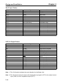
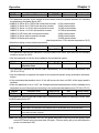
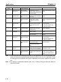
Note 1. Even when a U-series or U-UE-series Servomotor is used in combination with a100-VAC-input Position Driver, a 200-VAC Servomotor must be used. A 100-VAC Servomotor cannot be
connected.
Note 2. Straight-axis servomotors are available either with or without a key or brake. In the above
table, the Servomotors have the following features.
U-series
Straight axis without brake, without key
U-series UE models Straight axis without brake, with key (not available without key)
H-series
Straight axis without brake, with key
M-series
Straight axis without brake, with key (“A” cut for small-capacity)
Note 3. Motor control is enabled by setting the user parameter UP-02 of the Position Driver.
Note 4. U-series UE-type and H-series Servomotors can be used only with Position Driver software
version 4.01 (September 1997) or later.
U-series 1-kW to 2-kW Servomotors and M-series 1.1-kW to 2.2-kW Servomotors can be
used only with Position Driver software version 4.04 (April 1999) or later.
1-4
Chapter 1
Introduction
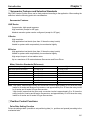
j Servomotor Features and Selection Standards
Any FND-X-series Position Driver can be freely selected according to the application. When making the
selection, take the following points into consideration.
D Servomotor Features
U/UE Series
Compact size, high-speed response
High resolution (except for UE type)
Absolute encoder system can be configured (except for UE type).
H Series
High resolution
High application load inertia (less than 10 times the rotary inertia)
Usable in systems with comparatively low mechanical rigidity.
M Series
High application load inertia (less than 10 times the rotary inertia)
Usable in systems with comparatively low mechanical rigidity.
High output torque in a low-rotation motor
Up to a maximum of 50 meters between Servomotor and Servo Driver.
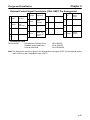
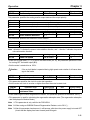
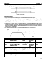
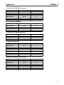
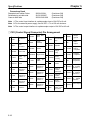
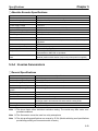
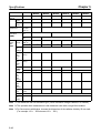
D Motor Selection Standards (Reference)
Drive system type
Ball screw direct connection
Turntable direct connection
Feeder (direct connection)
Harmonic drive
Chain drive
Belt drive
Rack & pinion
Low inertia
U, U-UE, H, M
U, U-UE, H, M
U, U-UE, H, M
U, U-UE, H, M
U, U-UE, H, M
U, U-UE, H, M
U, U-UE, H, M
High inertia
U, U-UE, H, M
U, U-UE, H, M
U, U-UE, H, M
H, M
H, M
H, M
H, M
Note “Low inertia” means that the motor axis conversion inertia is approximately 0 to 5 times the rotary
inertia for H-series and M-series Servomotors, and approximately 0 to 15 times the rotary inertia
for U-series and U-series UE-type Servomotors.
“High inertia” means that the motor axis conversion inertia is approximately 5 to 10 times the
rotary inertia for H-series and M-series Servomotors, and approximately 15 to 30 times the rotary
inertia for U-series and U-series UE-type Servomotors.
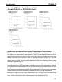
j Position Control Functions
D Pulse Rate Setting Function
Pulse rate setting makes it possible to set positioning data (i.e., positions and speeds) according to the
mechanical axis.
1-5
Chapter 1
Introduction
D Control Mode
The following four types of control modes are available to the Position Driver: PTP control and feeder
control modes with the internal point data preset in the Position Driver and these same modes with direct I/O signal input.
D Internal Point Data
• A maximum of 64 points of data (Pd01 to Pd64) can be set internally in the Position Driver.
• Positions can be set within a range between –39,999,999 to 39,999,999 with the absolute or incremental value specified.
D Positioning Data Instruction by Direct Input
Eight-point input and input timing signals are used to input position data and speed data within the following ranges into the Position Driver.
Position Setting Range:
–39,999,999 to 39,999,999 (with incremental or absolute setting)
Speed Setting Range:
1% to 100% (override setting with respect to reference speed)
D Position Compensation Function
This function executes backlash compensation when PTP control is used, and slip compensation when
feeder control is used.
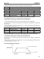
D Acceleration/Deceleration Function
• Either linear (trapezoidal) acceleration or deceleration time or S-shaped (primary low-pass filter) acceleration or deceleration time can be selected. In addition, different times can be set for acceleration
and deceleration.
• The S-shaped acceleration/deceleration function makes it possible, for example, to start up conveyors smoothly or achieve feeder control with minimal feeder slippage.
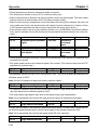
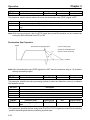
D Stop Methods
• The stop method for when the STOP signal is turned OFF can be selected with PP-24.
Free-running stop:
Motor power supply turned OFF.
Deceleration stop:
Servo-lock after the operation decelerates to a stop in preset time.
Error counter reset stop:
Servo-lock after an immediate deceleration to a stop with the error
counter reset.
• The stop method of the Position Driver in the case of overrun or software limit signal detection can be
selected with PP-25.
Overrun:
Servo free-running stop with the alarm AL38 turned ON or servolock stop.
Software limit detection:
Servo-lock stop with or without alarms AL34 and AL35 turned ON.
j Teaching Functions
D Position Teaching
The Position Driver has a teaching function that enables the Position Driver stop the mechanical axis
with an external force by going into servo-free status or JOG operation and to take up the stop position
data automatically as part of PTP data.
1-6
Introduction
Chapter 1
D Mechanical Origin Teaching
An optional position can be specified as the mechanical origin by moving the position to the mechanical
origin and teaching after the completion of origin search.
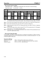
j Motor Control Functions
D Motor Type and Capacity Selection by Motor Code
A motor type and capacity can be selected by setting UP-02 to the corresponding motor code.
D Auto-tuning Function
• The Position Driver has an auto-tuning function. If a machine and motor are connected to the Position
Driver, this function makes it possible to check the capacity and characteristics of the machine load by
turning the motor and enables the automatic gain control of the Position Driver according to the capacity and characteristics of the machine load.
• The auto-tuning function makes it possible to save system startup time.
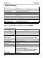
j Programming Devices
D Teaching Box: CVM1-PRO01 + ROM Cassette
The Teaching Box provides for easy operation, including the following:
Position Driver status monitoring
Parameter editing and transfer
Teaching
Jogging
Positioning to specified points
Autotuning
Note Refer to the CVM1-PRO01 Teaching Box Operation Manual (W354) for more information.
D OMNUC FND-X Series Monitoring Software
The OMNUC FND-X Series Monitoring Software runs on an IBM PC/AT or compatible computer and provides for easy operation, including the following:
Position Driver status monitoring
Parameter editing and transfer
Speed and current waveform displays
Autotuning
j Monitor Functions
D Monitor Mode
The motor speed, present value, reference value, position deviation value, machine speed, motor current, effective load factor, electronic thermal value, electrical angle, and regenerative absorption rate
can be monitored on the front panel of the Position Driver in this mode.
D Check Mode
The I/O signal status, alarm details, alarm history, and software version are displayed on the front panel
of the Position Driver in this mode.
1-7
Introduction
Chapter 1
j Protection and Self-diagnostic Functions
D Hardware Protection
The Position Driver is protected from overcurrent, overvoltage, low voltage, abnormal power, clock failure, overcurrent (soft), speed amplifier saturation, and overload damage.
D Mechanical System Protection
The mechanical system is protected from damage resulting from overspeed, error counter overflows,
soft limit overflows, coordinate counter overflows, or overrun.
D Parameter Setting-related Errors
The Position Driver detects parameter setting errors.
D Detector-related Errors
Resolver wire burnout, resolver failure, encoder wire disconnection, encoder communications failure,
absolute encoder backup failure, absolute encoder checksum failure, absolute encoder battery failure,
absolute encoder absolute failure, absolute encoder overspeed failure, encoder data failure, and encoder initialization failure.
D Position-related Errors
BCD data, indefinite PV, and PTP data non-setting errors.
j Test Functions
D Motor Test Function
The Position Driver has a motor test function that makes it possible to easily check whether a motor is
connected to the Position Driver. When this function is enabled, the motor rotation direction can be controlled with the operation keys and the motor speed can be set in UP-29. The motor speed is set to
50 r/min before shipping.
D Sequential Output Test Function
The Position Driver has a sequential output test function that makes it possible to easily check whether a
host controller is connected to the Position Driver. This function makes it possible to turn any output
terminal ON or OFF with the operation keys.
1-8
Chapter 1
Introduction
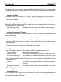
1-2
Nomenclature and Key Operations
D DIO Position Drivers
Front View
Display
(5-digit, 7-segment LEDs)
Operation Keys (5 keys)
Monitor Output Terminal
CN5 (RS-232C)
Communications
Connector
CN1 (CONT)
Control Signal
Connector
Terminal
Block
CN2 (M.SEN)
Motor Sensor
Connector
Bottom View
Radiation
fin
CN6
BAT
Connector
j Key Operations
Key
DATA
Name
Mode Key
Main function
Changes the Position Driver’s mode.
Shift Key
Shifts the operation column to the left.
Data Key
Saves the set data.
Increment Key
Increments the parameter address or
data value.
Decrements the parameter address or
data value.
Decrement Key
1-9
Chapter 1
Introduction
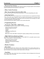
D CompoBus/S Position Drivers
Front View
Display
(5-digit, 7-segment LEDs)
Operation Keys (5 keys)
Monitor Output Terminal
CN5 (RS-232C)
Communications
Connector
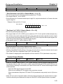
Node Address
Setting Switch
Terminal
Block
CN1 (CONT)
Control Signal
Connector
CN4 (LIMIT)
External control
signal connector
CN2 (M.SEN)
Motor Sensor
Connector
Bottom View
Radiation fin
CN6
BAT Connector
j Key Operations
Key
DATA
Name
Mode Key
Main function
Changes the Position Driver’s mode.
Shift Key
Shifts the operation column to the left.
Data Key
Saves the set data.
Increment Key
Increments the parameter address or
data value.
Decrements the parameter address or
data value.
Decrement Key
1-10
Chapter 1
Introduction
1-3
Supported Standards and Supporting Models
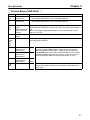
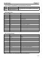
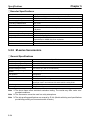
1-3-1 Standards Supported by Position Drivers
Standard
UL/cUL
EC Low-voltage Directive
EMC Directive
Supported standard File No.
UL508C
E179149
EN50178
--EN55011 class A
--group 1
EN61000-4
---
Remarks
Electrical power conversion devices
Industrial product specifications
Radio interference limits and measurement
methods for radio frequency devices for industrial, scientific, and medical applications
Electromagnetic compatibility and immunity
Note All Position Drivers in the FND-X Series conform to UL/cUL standards and EC directives.
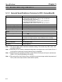
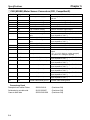
1-3-2 Standards Supported by AC Servomotors
Standard
Supported standard
UL1004
cUL C22.2 No. 100
Low-voltage Directive IEC34-1, -5, -8, -9
EMC Directive
EN55011 class A
group 1
UL/cUL
EC
EN61000-4
File No.
E179189
E179189
-----
---
Remarks
Electric motors
Motors and generators
Rotating electric devices
Radio interference limits and measurement
methods for radio frequency devices for industrial, scientific, and medical applications
Electromagnetic compatibility and immunity
j Servomotors Conforming to UL/cUL Standards
Power supply
200 VAC
200 VAC
AC Servomotors
R88M-U30HA- (30 to 750 W)
R88M-U30TA- (30 to 750 W)
Encoder
Incremental encoder
Absolute encoder
Note Servomotors manufactured beginning in May 1998 conform to UL/cUL standards.
j Servomotors Conforming EC Directives
Power supply
200 VAC
200 VAC
200 VAC
200 VAC
200 VAC
AC Servomotors
R88M-U30VA- (30 to 750 W)
R88M-U30XA- (30 to 750 W)
R88M-UE30V- (100 to 750 W)
R88M-U30V- (1 to 2 kW)
R88M-U30X- (1 to 2 kW)
Encoder
Incremental encoder
Absolute encoder
Incremental encoder
Incremental encoder
Absolute encoder
Note The Servomotors must be wired as described in 2-2 Wiring to conform to the EMC Directive.
1-11
2
Chapter 2
Design and Installation
2-1
2-2
Installation
Wiring
Chapter 2
Design and Installation
2-1
Installation
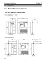
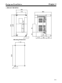
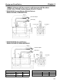
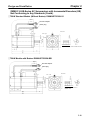
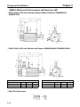
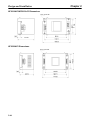
2-1-1 External Dimensions (Unit: mm)
DIO and CompoBus/S Position Drivers
j 200-VAC FND-X06H-/-X12H-
100-VAC FND-X06L-/-X12L-
Mounting Dimensions
Three, 6 dia.
Three, M5
j 200-VAC FND-X25H-
Mounting Dimensions
Three, 6 dia.
2-2
Three, M5
Chapter 2
Design and Installation
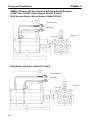
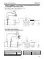
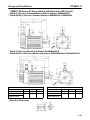
j 200-VAC FND-X50H-
Four, 6 dia.
Mounting Dimensions
Four, M5
2-3
Chapter 2
Design and Installation
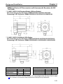
OMNUC U-Series AC Servomotors with Incremental Encoders
(U-INC 30 to 750 W) Conforming to UL/cUL
j 30-W/50-W/100-W Standard Models (Without Brakes):
R88M-U03030HA, R88M-U05030HA, R88M-U10030HA
300±30
35
Encoder adapter
Motor plug
6.5
18
14 dia.
300±30
6
6h6 dia.
2.5
Two, 4.3 dia.
30h7 dia.
17
9.5
5
Four, R3.7
6
40
46 dia.
33
40
LL
25
L
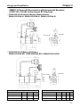
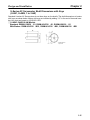
j 30-W/50-W/100-W Models with Brakes:
R88M-U03030HA-B, R88M-U05030HA-B, R88M-U10030HA-B
300±30
35
Encoder adapter
Motor plug
21
14 dia.
2.5
Two, 4.3 dia.
30h7 dia.
17
5
33
LB
LL
Four, R3.7
4
46 dia.
40
9.5
6.5
6h6 dia.
300±30
40
25
L
Standard Models (Without Brakes)
Model
L
LL
S
R88M-U03030HA 94.5
69.5
6
R88M-U05030HA 102.0
77.0
6
R88M-U10030HA 119.5
94.5
8
2-4
Models with Brakes
Model
L
LL
R88M-U03030HA-B 126
101
R88M-U05030HA-B 133.5 108.5
R88M-U10030HA-B 160
135
LB
S
31.5 6
31.5 6
40.5 8
Chapter 2
Design and Installation
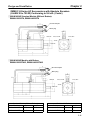
OMNUC U-Series AC Servomotors with Incremental Encoders
(U-INC 30 to 750 W) Conforming to UL/cUL (Contd.)
j 200-W/400-W Standard Models (Without Brakes):
R88M-U20030HA, R88M-U40030HA
300±30
35
Encoder adapter
Motor plug
21
14 dia.
12
3
Four, 5.5 dia.
50h7 dia.
17
6
Four, R5.3
70 dia.
60
7
14h6 dia.
300±30
5.2
34
60
LL
30
L
j 200-W/400-W Models with Brakes:
R88M-U20030HA-B, R88M-U40030HA-B
300±30
35
Encoder adapter
Motor plug
21
14 dia.
Four,
5.5 dia.
50h7 dia.
3
34
Four, R5.3
60
12
6
70 dia.
7
17
5.5
14h6 dia.
300±30
5.2
60
39.5
LL
30
L
Standard Models (Without Brakes)
Model
L
LL
R88M-U20030HA
126.5
96.5
R88M-U40030HA
154.5
124.5
Models with Brakes
Model
L
LL
R88M-U20030HA-B 166
136
R88M-U40030HA-B 194
164
2-5
Chapter 2
Design and Installation
OMNUC U-Series AC Servomotors with Incremental Encoders
(U-INC 30 to 750 W) Conforming to UL/cUL (Contd.)
j 750-W Standard Models (Without Brakes): R88M-U75030HA
300±30
35
Encoder adapter
Motor plug
21
14 dia.
300±30
8
15
3
Four, R8.2
35
80
90 dia.
16h6 dia.
Four, 7 dia.
70h7 dia.
8
17
5.2
34
80
145
40
185
j 750-W Models with Brakes: R88M-U75030HA-B
300±30
35
Encoder adapter
Motor plug
21
14 dia.
300±30
8
15
Four, R8.2
3
35
34
44.5
80
80
189.5
229.5
2-6
90 dia.
Four, 7 dia.
70h7 dia.
8
16h6 dia.
17
5.2
40
Chapter 2
Design and Installation
OMNUC U-Series AC Servomotors with Incremental Encoders
(U-INC 30 to 750 W) Conforming to EC Directives
j 30-W/50-W/100-W Standard Models (Without Brakes):
R88M-U03030VA-S1, R88M-U05030VA-S1, R88M-U10030VA-S1
Sh6 dia.
14 dia.
Four, R3.7
30h7 dia.
46 dia.
Two, 4.3 dia.
j 30-W/50-W/100-W Models with Brakes:
R88M-U03030VA-BS1, R88M-U05030VA-BS1, R88M-U10030VA-BS1
Standard Models (Without Brakes)
Model
L
LL
S
R88M-U03030VA-S1 94.5
69.5
6
R88M-U05030VA-S1 102.0
77.0
6
R88M-U10030VA-S1 119.5
94.5
8
Four, R3.7
46 dia.
Two, 4.3 dia.
30h7 dia.
Sh6 dia.
14 dia.
Models with Brakes
Model
L
LL
R88M-U03030VA-BS1 126
101
R88M-U05030VA-BS1 133.5 108.5
R88M-U10030VA-BS1 160
135
LB
S
31.5 6
31.5 6
40.5 8
2-7
Chapter 2
Design and Installation
OMNUC U-Series AC Servomotors with Incremental Encoders
(U-INC 30 to 750 W) Conforming to EC Directives (Contd.)
j 200-W/400-W Standard Models (Without Brakes):
R88M-U20030VA-S1, R88M-U40030VA-S1
Four, R5.3
70 dia.
Four, 5.5 dia.
50h7 dia.
14h6 dia.
14 dia.
j 200-W/400-W Models with Brakes:
R88M-U20030VA-BS1, R88M-U40030VA-BS1
Standard Models (Without Brakes)
Model
L
LL
R88M-U20030VA-S1 126.5
96.5
R88M-U40030VA-S1 154.5
124.5
2-8
Four, R5.3
70 dia.
Four, 5.5 dia.
50h7 dia.
14h6 dia.
14 dia.
Models with Brakes
Model
L
R88M-U20030VA-BS1 166
R88M-U40030VA-BS1 194
LL
136
164
Chapter 2
Design and Installation
OMNUC U-Series AC Servomotors with Incremental Encoders
(U-INC 30 to 750 W) Conforming to EC Directives (Contd.)
j 750-W Standard Models (Without Brakes): R88M-U75030VA-S1
14 dia.
Four, R8.2
90 dia.
70h7 dia.
16h6 dia.
Four, 7 dia.
j 750-W Models with Brakes: R88M-U75030VA-BS1
14 dia.
Four, R8.2
90 dia.
70h7 dia.
16h6 dia.
Four, 7 dia.
2-9
Chapter 2
Design and Installation
OMNUC U-Series AC Servomotors with Absolute Encoders
(U-ABS 30 to 750 W) Conforming to UL/cUL
j 30-W/50-W/100-W Standard Models (Without Brakes):
R88M-U03030TA, R88M-U05030TA, R88M-U10030TA
Encoder adapter
Motor plug
14 dia.
Sh6 dia.
Four, R3.7
Two, 4.3 dia.
46 dia.
53 dia.
30h7 dia.
j 30-W/50-W/100-W Models with Brakes:
R88M-U03030TA-B, R88M-U05030TA-B, R88M-U10030TA-B
Encoder adapter
Motor plug
14 dia.
Sh6 dia.
Two, 4.3 dia.
Four, R3.7
46 dia.
53 dia.
Standard Models (Without Brakes)
Model
L
LL
S
R88M-U03030TA
117.5
92.5
6
R88M-U05030TA
125
100
6
R88M-U10030TA
142.5
117.5
8
2-10
30h7 dia.
Models with Brakes
Model
L
LL
R88M-U03030TA-B 149
124
R88M-U05030TA-B 156.5 131.5
R88M-U10030TA-B 183
158
LB
31.5
31.5
40.5
S
6
6
8
Chapter 2
Design and Installation
OMNUC U-Series AC Servomotors with Absolute Encoders
(U-ABS 30 to 750 W) Conforming to UL/cUL (Contd.)
j 200-W/400-W Standard Models (Without Brakes):
R88M-U20030TA, R88M-U40030TA
Encoder adapter
Motor plug
14 dia.
14h6 dia.
Four, R5.3
Four, 5.5.dia.
70 dia.
50h7 dia.
j 200-W/400-W Models with Brakes:
R88M-U20030TA-B, R88M-U40030TA-B
Encoder adapter
Motor plug
14 dia.
14h6 dia.
Four, 5.5.dia.
Four, R5.3
70 dia.
50h7 dia.
Standard Models (Without Brakes)
Model
L
LL
R88M-U20030TA
147.5
117.5
R88M-U40030TA
175.5
145.5
Models with Brakes
Model
L
R88M-U20030TA-B
187
R88M-U40030TA-B
215
LL
157
185
2-11
Chapter 2
Design and Installation
OMNUC U-Series AC Servomotors with Absolute Encoders
(U-ABS 30 to 750 W) Conforming to UL/cUL (Contd.)
j 750-W Standard Models (Without Brakes): R88M-U75030TA
Encoder adapter
Motor plug
14 dia.
Four, R8.2
Four, 7 dia.
16h6 dia.
90 dia.
70h7 dia.
j 750-W Models with Brakes: R88M-U75030TA-B
Encoder adapter
Motor plug
14 dia.
Four, R8.2
Four, 7 dia.
16h6 dia.
90 dia.
70h7 dia.
2-12
Chapter 2
Design and Installation
OMNUC U-Series AC Servomotors with Absolute Encoders
(U-ABS 30 to 750 W) Conforming to EC Directives
j 30-W/50-W/100-W Standard Models (Without Brakes):
R88M-U03030XA-S1, R88M-U05030XA-S1, R88M-U10030XA-S1
Sh6 dia.
14 dia.
46 dia.
30h7 dia.
53 dia.
Four, R3.7
Two, 4.3 dia.
j 30-W/50-W/100-W Models with Brakes:
R88M-U03030XA-BS1, R88M-U05030XA-BS1, R88M-U10030XA-BS1
Sh6 dia.
14 dia.
Standard Models (Without Brakes)
Model
L
LL
S
R88M-U03030XA-S1 117.5
92.5
6
R88M-U05030XA-S1 125
100
6
R88M-U10030XA-S1 142.5
117.5
8
30h7 dia.
53 dia.
Two, 4.3 dia.
Four, R3.7
46 dia.
Models with Brakes
Model
L
LL
R88M-U03030XA-BS1 149
124
R88M-U05030XA-BS1 156.5 131.5
R88M-U10030XA-BS1 183
158
LB S
31.5 6
31.5 6
40.5 8
2-13
Chapter 2
Design and Installation
OMNUC U-Series AC Servomotors with Absolute Encoders
(U-ABS 30 to 750 W) Conforming to EC Directives (Contd.)
j 200-W/400-W Standard Models (Without Brakes):
R88M-U20030XA-S1, R88M-U40030XA-S1
14h6 dia.
14 dia.
Four, 5.5 dia.
Four, R5.3
50h7 dia.
70 dia.
j 200-W/400-W Models with Brakes:
R88M-U20030XA-BS1, R88M-U40030XA-BS1
14h6 dia.
14 dia.
50h7 dia.
Four, 5.5 dia.
Standard Models (Without Brakes)
Model
L
LL
R88M-U20030XA-S1 147.5
117.5
R88M-U40030XA-S1 175.5
145.5
2-14
Four, R5.3
70 dia.
Models with Brakes
Model
L
R88M-U20030XA-BS1 187
R88M-U40030XA-BS1 215
LL
157
185
Chapter 2
Design and Installation
OMNUC U-Series AC Servomotors with Absolute Encoders
(U-ABS, 30 to 750 W) Conforming to EC Directives (Contd.)
j 750-W Standard Models (Without Brakes): R88M-U75030XA-S1
14 dia.
Four, R8.2
16h6 dia.
70h7 dia.
Four, 7 dia.
90 dia.
j 750-W Models with Brakes: R88M-U75030XA-BS1
14 dia.
Four, R8.2
90 dia.
70h7 dia.
16h6 dia.
Four, 7 dia.
2-15
Chapter 2
Design and Installation
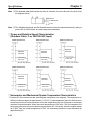
U-Series AC Servomotor Shaft Dimensions with Keys
(U-INC, U-ABS, 30 to 750 W)
Standard U-series AC Servomotors do not have keys on the shafts. The shaft dimensions of motors
with keys are shown below. Motors with keys are indicated by adding “-S1” to the end of the model number. Key slots are based on JIS B1301-1976.
j 30-W/50-W Models
Standard: R88M-U03030-S1, R88M-U05030-S1
With Brakes: R88M-U03030-BS1, R88M-U05030-BS1
14
Dia.: 6h6
1.2
2
2
j 100-W Models
Standard: R88M-U10030-S1
With Brakes: R88M-U10030-BS1
14
Dia.: 8h6
1.8
3
3
j 200-W/400-W Models
Standard: R88M-U20030-S1, R88M-U40030-S1
With Brakes: R88M-U20030-BS1, R88M-U40030-BS1
20
Dia.: 14h6
3
5
5
j 750-W Models
Standard: R88M-U75030-S1
With Brakes: R88M-U75030-BS1
30
Dia.: 16h6
3
5
5
2-16
Chapter 2
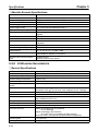
Design and Installation
OMNUC U-UE-Series AC Servomotors with Incremental Encoders (UE)
Not Conforming to Any Standards
j 100-W Standard Models (Without Brakes): R88M-UE10030H-S1
Encoder adapter
Motor plug
Shaft end dimensions
Key slot dimensions, conform to JIS B1301-1976.
8h6 dia.
Four, R3.7
30h7 dia.
8h6 dia.
Two, 4.3 dia.
46 dia.
j 100-W Models with Brakes: R88M-UE10030H-BS1
Encoder adapter
Motor plug
Shaft end dimensions
30h7 dia.
Two, 4.3 dia.
46 dia.
8h6 dia.
8h6 dia.
Key slot dimensions, conform to JIS B1301-1976.
Four, R3.7
2-17
Chapter 2
Design and Installation
OMNUC U-UE-Series AC Servomotors with Incremental Encoders (UE)
(Contd.)
j 200-W/400-W Standard Models (Without Brakes):
R88M-UE20030H-S1, R88M-UE40030H-S1
Encoder adapter
Motor plug
Shaft end dimensions
14h6 dia.
Key slot dimensions, conform to JIS B1301-1976.
Four, R5.3
14h6 dia.
50h7 dia.
Four, 5.5 dia.
70 dia.
j 200-W/400-W Models with Brakes:
R88M-UE20030H-BS1, R88M-UE40030H-BS1
Encoder adapter
Motor plug
Shaft end dimensions
50h7 dia.
70 dia.
Standard Models (Without Brakes)
Model
L
LL
R88M-UE20030H-S1 126.5
96.5
R88M-UE40030H-S1 154.5
124.5
2-18
Four, R5.3
14h6 dia.
14h6 dia.
Key slot dimensions, conform to JIS B1301-1976.
Four, 5.5 dia.
Models with Brakes
Model
L
R88M-UE20030H-BS1 166
R88M-UE40030H-BS1 194
LL
136
164
Chapter 2
Design and Installation
OMNUC U-UE-Series AC Servomotors with Incremental Encoders (UE)
Not Conforming to Any Standards (Contd.)
j 750-W Standard Models (Without Brakes): R88M-UE75030H-S1
Encoder adapter
Motor plug
Four, R8.2
16h6 dia.
90 dia.
70h7 dia.
16h6 dia.
Four, 7 dia.
Shaft end dimensions
Key slot dimensions, conform to JIS B1301-1976.
j 750-W Models with Brakes: R88M-UE75030H-BS1
Encoder adapter
Motor plug
Four, R8.2
16h6 dia.
90 dia.
70h7 dia.
16h6 dia.
Four, 7 dia.
Shaft end dimensions
Key slot dimensions, conform to
JIS B1301-1976.
2-19
Chapter 2
Design and Installation
OMNUC U-UE-Series AC Servomotors with Incremental Encoders (UE)
Conforming to EC Directives
j 100-W Standard Models (Without Brakes): R88M-UE10030V-S1
14 dia.
8h6 dia.
Shaft end dimensions
Four, R3.7
Key slot dimensions, conform to JIS B1301-1976.
30h7 dia.
Two, 4.3 dia.
46 dia.
j 100-W Models with Brakes: R88M-UE10030V-BS1
14 dia.
2-20
46 dia.
Four, R3.7
8h6 dia.
Key slot dimensions, conform to JIS B1301-1976.
Two, 4.3 dia.
30h7 dia.
8h6 dia.
Shaft end dimensions
Chapter 2
Design and Installation
OMNUC U-UE-Series AC Servomotors with Incremental Encoders (UE)
Conforming to EC Directives (Contd.)
j 200-W/400-W Standard Models (Without Brakes):
R88M-UE20030V-S1, R88M-UE40030V-S1
14h6 dia.
14 dia.
Four, 5.5 dia.
Four, R5.3
Shaft end dimensions
Key slot dimensions, conform to JIS B1301-1976.
50h7 dia.
14h6 dia.
70 dia.
j 200-W/400-W Models with Brakes:
R88M-UE20030V-BS1, R88M-UE40030V-BS1
14h6 dia.
14 dia.
Four, 5.5 dia.
Shaft end dimensions
Key slot dimensions, conform to
JIS B1301-1976.
14h6 dia.
50h7 dia.
70 dia.
Standard Models (Without Brakes)
Model
L
LL
R88M-UE20030V-S1 126.5
96.5
R88M-UE40030V-S1 154.5
124.5
Four, R5.3
Models with Brakes
Model
L
R88M-UE20030V-BS1 166
R88M-UE40030V-BS1 194
LL
136
164
2-21
Chapter 2
Design and Installation
OMNUC U-UE-Series AC Servomotors with Incremental Encoders (UE)
Conforming to EC Directives (Contd.)
j 750-W Standard Models (Without Brakes): R88M-UE75030V-S1
Shaft end dimensions
16h6 dia.
Key slot dimensions, conform to JIS B1301-1976.
14 dia.
Four, R8.2
16h6 dia.
Four, 7 dia.
70h7 dia.
90 dia.
j 750-W Models with Brakes: R88M-UE75030V-BS1
Shaft end dimensions
16h6 dia.
Key slot dimensions, conform to JIS B1301-1976.
14 dia.
Four, R8.2
16h6 dia.
Four, 7 dia.
70h7 dia.
90 dia.
2-22
Chapter 2
Design and Installation
OMNUC U-Series AC Servomotors with Incremental Encoders (U-INC
1 to 2 kW)
95h7 dia.
24h6 dia.
j 1.0-kW/1.5-kW/2.0-kW Standard Models (Without Brakes)
Not Conforming to Any Standards: R88M-U1K030H/-U1K530H/-U2K030H
Conforming to EC Directives: R88M-U1K030V-S1/-U1K530V-S1/-U2K030V-S1
130 dia.
115 dia.
Four, 7 dia.
95h7 dia.
24h6 dia.
j 1.0-kW/1.5-kW/2.0-kW Models With Brakes
Not Conforming to Any Standards: R88M-U1K030H-B/-U1K530H-B/-U2K030H-B
Conforming to EC Directives: R88M-U1K030V-BS1/-U1K530V-BS1/-U2K030V-BS1
130 dia.
115 dia.
Four, 7 dia.
Standard Models (Without Brakes)
Model
L
LL
R88M-U1K030
194
149
R88M-U1K530
220
175
R88M-U2K030
243
198
Models with Brakes
Model
L
R88M-U1K030-B
238
R88M-U1K530-B
264
R88M-U2K030-B
287
LL
193
219
242
Note Servomotors with model numbers ending in “S1” have straight shafts with keys. Refer to page
2-25 U-Series AC Servomotor Shaft Dimensions with Keys for key dimensions.
2-23
Chapter 2
Design and Installation
OMNUC U-Series AC Servomotors with Absolute Encoders (U-ABS
1 to 2 kW)
95h7 dia.
24h6 dia.
j 1.0-kW/1.5-kW/2.0-kW Standard Models (Without Brakes)
Not Conforming to Any Standards: R88M-U1K030T/-U1K530T/-U2K030T
Conforming to EC Directives: R88M-U1K030X-S1/-U1K530X-S1/-U2K030X-S1
130 dia.
115 dia.
Four, 7 dia.
95h7 dia.
24h6 dia.
j 1.0-kW/1.5-kW/2.0-kW Models With Brakes
Not Conforming to Any Standards: R88M-U1K030T-B/-U1K530T-B/-U2K030T-B
Conforming to EC Directives: R88M-U1K030X-BS1/-U1K530X-BS1/-U2K030X-BS1
130 dia.
115 dia.
Four, 7 dia.
Standard Models (Without Brakes)
Model
L
LL
R88M-U1K030
208
163
R88M-U1K530
234
189
R88M-U2K030
257
212
Models with Brakes
Model
L
R88M-U1K030-B
252
R88M-U1K530-B
278
R88M-U2K030-B
301
LL
207
233
256
Note Servomotors with model numbers ending in “S1” have straight shafts with keys. Refer to page
2-25 U-Series AC Servomotor Shaft Dimensions with Keys for key dimensions.
2-24
Chapter 2
Design and Installation
U-Series AC Servomotor Shaft Dimensions with Keys
(U-INC, U-ABS, 1 to 2 kW)
Standard U-series AC Servomotors do not have keys on the shafts. The shaft dimensions of motors
with keys are shown below. Motors with keys are indicated by adding “-S1” to the end of the model number. Key slots are based on JIS B1301-1976.
24h6 dia.
j 1.0-kW/1.5-kW/2.0-kW Models
Standard: R88M-U1K030-S1, R88M-U1K530-S1, R88M-U2K030-S1
With Brakes: R88M-U1K030-BS1, R88M-U1K530-BS1, R88M-U2K030-BS1
M8 with effective
depth of 16
2-25
Chapter 2
Design and Installation
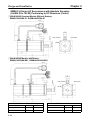
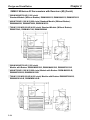
OMNUC H-Series AC Servomotor with Incremental Encoder (H)
j 50-W/100-W Standard Models (Without Brakes): R88M-H05030, R88M-H10030
j 50-W/100-W Models with Brakes: R88M-H05030-B, R88M-H10030-B
Four, R4
8
93 dia. max.
63 dia.
50
0 dia.
0.009
0 dia.
0.025
80±0.2 dia.
Four, 5 dia.
66
Standard Models (Without Brakes)
Model
L1
L2
L3
R88M-H05030 (50 W)
53.5
99
45.5
R88M-H10030 (100 W) 63.5
109
45.5
66±0.4
Models With Brakes
Model
L1
L2
R88M-H05030-B (50 W) 84.5
130
R88M-H10030-B (100 W) 94.5
140
L3
45.5
45.5
j 200-W/300-W Standard Models (Without Brakes): R88M-H20030, R88M-H30030
j 200-W/300-W Models with Brakes: R88M-H20030-B, R88M-H30030-B
Four, R10
14
107 dia. max.
77 dia.
70
0 dia.
0.011
0 dia.
0.03
90±0.2 dia.
Four, 6 dia.
Standard Models (Without Brakes)
Model
L1
L2
L3
R88M-H20030 (200 W) 77
123.5 46.5
R88M-H30030 (300 W) 89
135.5 46.5
2-26
80
80±0.4
Models With Brakes
Model
L1
L2
R88M-H20030-B (200 W) 107.5 154
R88M-H30030-B (300 W) 119.5 166
L3
46.5
46.5
Chapter 2
Design and Installation
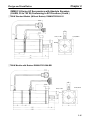
OMNUC H-Series AC Servomotors with Incremental Encoders (H)
(Contd.)
j 500-W/750-W/1100-W Standard Models (Without Brakes):
R88M-H50030, R88M-H75030, R88M-H1K130
j 500-W/750-W/1100-W Models with Brakes:
R88M-H50030-B, R88M-H75030-B, R88M-H1K130-B
Four, R15
162 dia. max.
77 dia.
110
0 dia.
0.035
130±0.2 dia.
Four, 9 dia.
Shaft Dimensions
R88M-H50030/-H50030-B
R88M-H75030/-H75030-B
16
0 dia.
0.011
Shaft Dimensions
R88M-H1K130/-H1K130-B
19
0 dia.
0.013
Standard Models (Without Brakes)
Model
L1
L2
L3
R88M-H50030 (500 W)
107.5 154.0 46.5
R88M-H75030 (750 W)
126.0 172.5 46.5
R88M-H1K130 (1100 W) 144.5 191.0 46.5
Models With Brakes
Model
L1
L2
L3
R88M-H50030-B (500 W)
148.5 195.0 46.5
R88M-H75030-B (750 W)
167.0 213.5 46.5
R88M-H1K130-B (1100 W) 185.5 232.0 46.5
2-27
Chapter 2
Design and Installation
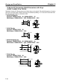
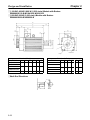
OMNUC M-Series AC Servomotors with Resolvers (M)
j 60-W/120-W (4,000 r/min) Standard Models (Without Brakes): R88M-M06040,
R88M-M12040
8h6 dia.
50h7 dia.
7.4 dia.
…
Four, 5 dia.
j 60-W/120-W (4,000 r/min) Models with Brakes: R88M-M06040-B, R88M-M12040-B
50h7 dia.
8h6 dia.
7.4 dia.
°
°
Four, 5 dia.
Standard Models (Without Brakes)
Model
L
LL
LM
R88M-M06040
150
120
85
R88M-M12040
175
145
110
j Shaft End Dimensions
2-28
Models with Brakes
Model
LX
LY
R88M-M06040-B
184
154
R88M-M12040-B
209
179
LM
85
110
Chapter 2
Design and Installation
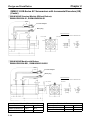
OMNUC M-Series AC Servomotors with Resolvers (M) (Contd.)
j 200-W (2,000 r/min) Standard Models (Without Brakes): R88M-M20020
j 200-W/400-W (4,000 r/min) Standard Models: R88M-M20040, R88M-40040
14h6 dia.
80h7 dia.
7.4 dia.
100±0.2 dia
Four, 7dia.
j 200-W (2,000 r/min) Models with Brakes: R88M-M20020-B
j 200-W/400-W (4,000 r/min) Models with Brakes: R88M-M20040-B, R88M-M40040-B
80h7 dia.
14h6 dia.
7.4 dia.
100±0.2 dia
Four, 7dia.
Standard Models (Without Brakes)
Model
L
LL
LM
R88M-M20040
166
131
92
196
161
122
R88M-M20020
R88M-M40040
Models with Brakes
Model
LX
LY
R88M-M20040-B
196
161
226
191
R88M-M20020-B
R88M-M40040-B
LM
92
122
j Shaft End Dimensions
2-29
Chapter 2
Design and Installation
OMNUC M-Series AC Servomotors with Resolvers (M) (Contd.)
j 200-W/400-W/700-W (1,200 r/min)
Standard Models (Without Brakes): R88M-M20012, R88M-M40012, R88M-M70012
j 400-W/700-W/1,100-W (2,000 r/min) Standard Models (Without Brakes):
R88M-M40020, R88M-M70020, R88M-M1K120
19h6 dia.
110h7 dia.
j 700-W/1,100-W/2,000-W (4,000 r/min) Standard Models (Without Brakes):
R88M-70040, R88M-M1K140, R88M-M2K040
145±0.2 dia.
Four, 9 dia.
j 200-W/400-W/700-W (1,200 r/min)
Models with Brakes: R88M-M20012-B, R88M-M40012-B, R88M-M70012-B
j 400-W/700-W/1,100-W (2,000 r/min) Models with Brakes: R88M-M40020-B,
R88M-M70020-B, R88M-M1K120B
19h6 dia.
110h7 dia.
j 700-W/1,100-W/2,000-W (4,000 r/min) Models with Brakes: R88M-M70040-B,
R88M-M1K140-B, R88M-M2K040-B
145±0.2 dia.
165 dia.
Four, 9 dia.
2-30
Chapter 2
Design and Installation
Standard Models
Model
R88M-M20012
R88M-M40020
R88M-M70040
R88M-M40012
R88M-M70020
R88M-M1K140
R88M-M70012
R88M-M1K120
R88M-M2K040
Models with Brakes
L
240
LL
195
LM
156
275
230
191
345
300
261
Model
R88M-M20012-B
R88M-M40020-B
R88M-M70040-B
R88M-M40012-B
R88M-M70020-B
R88M-M1K140-B
R88M-M70012-B
R88M-M1K120-B
R88M-M2K040-B
LX
282
LY
237
LM
156
317
272
191
387
342
261
j Shaft End Directions
OMNUC M-Series AC Servomotors with Resolvers (Contd.)
j 1,100-W/1,400-W/1,800-W (1,200 r/min) Standard Models:
R88M-M1K112/-M1K412/-M1K812
180 x 180
114.3h7
0
35
+0.01
dia.
j 1,800-W/2,200-W (2,000 r/min) Standard Models:
R88M-M1K820/-M2K220
200±0.3 dia.
Four, 14 dia.
230 dia.
2-31
Chapter 2
Design and Installation
180 x 180
0
114.3h7
35
+0.01
dia.
j 1,100-W/1,400-W/1,800-W (1,200 r/min) Models with Brakes:
R88M-M1K112-B/-M1K412-B/-M1K812-B
j 1,800-W/2,200-W (2,000 r/min) Models with Brakes:
R88M-M1K820-B/-M2K220-B
200±0.3 dia.
Four, 14 dia.
230 dia.
Standard Models
Model
L
LL LM LX LY LZ
R88M-M1K112 370 291 252 439 360 256
R88M-M1K820
R88M-M1K412 400 321 282 469 390 286
R88M-M2K220
R88M-M1K812 460 381 342 529 450 346
Models with Brakes
Model
L
LL
LM
LX
LY
LZ
R88M-M1K112-B
R88M-M1K820-B
370
291
252
439
360
256
R88M-M1K412-B
R88M-M2K220-B
400
321
282
469
390
286
R88M-M1K812-B
460
381
342
529
450
346
j Shaft End Directions
4.5
10 h9
C1
60
R5
2-32
8
Chapter 2
Design and Installation
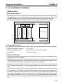
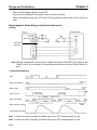
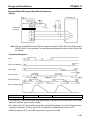
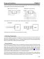
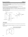
2-1-2 Installation Conditions
Position Driver
j Space Around Drivers
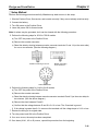
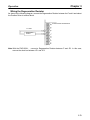
• Install Position Drivers according to the dimensions shown in the following illustration to ensure proper heat dispersion and convection inside the panel. Also install a fan for circulation if Position Drivers
are installed side by side to prevent uneven temperatures from developing inside the panel.
• Mount the Position Drivers vertically (so that the model number and writing can be read).
ÉÉÉÉÉÉÉÉÉÉÉÉÉÉÉÉÉÉÉÉÉÉ
ÉÉÉÉÉÉÉÉÉÉÉÉÉÉÉÉÉÉÉÉÉÉ
ÉÉÉÉÉÉÉÉÉÉÉÉÉÉÉÉÉÉÉÉÉÉ
ÉÉÉÉÉÉÉÉÉÉÉÉÉÉÉÉÉÉÉÉÉÉ
ÉÉÉÉÉÉÉÉÉÉÉÉÉÉÉÉÉÉÉÉÉÉ
ÉÉÉÉÉÉÉÉÉÉÉÉÉÉÉÉÉÉÉÉÉÉ
ÉÉÉÉÉÉÉÉÉÉÉÉÉÉÉÉÉÉÉÉÉÉ
ÉÉÉÉÉÉÉÉÉÉÉÉÉÉÉÉÉÉÉÉÉÉ
ÉÉÉÉÉÉÉÉÉÉÉÉÉÉÉÉÉÉÉÉÉÉ
ÉÉÉÉÉÉÉÉÉÉÉÉÉÉÉÉÉÉÉÉÉÉ
ÉÉÉÉÉÉÉÉÉÉÉÉÉÉÉÉÉÉÉÉÉÉ
ÉÉÉÉÉÉÉÉÉÉÉÉÉÉÉÉÉÉÉÉÉÉ
ÉÉÉÉÉÉÉÉÉÉÉÉÉÉÉÉÉÉÉÉÉÉ
W
30 mm min.
50 mm min.
Position Driver
Fan
Position Driver
Position Driver
Fan
Side of Driver
W
W = 10 mm min.
50 mm min.
j Operating Environment
Be sure that the environment in which Position Drivers are operated meets the following conditions.
• Ambient operating temperature:
0°C to +55°C
• Ambient operating humidity:
35% to 90% (RH, with no condensation)
• Atmosphere:
No corrosive gases.
j Ambient Temperature
• Position Drivers should be operated in environments in which there is minimal temperature rise to
maintain a high level of reliability.
• Temperature rise in any Position Driver installed in a closed space, such as a control box, will cause
the ambient temperature to rise inside the entire closed space. Use a fan or a air conditioner to prevent the ambient temperature of the Position Driver from exceeding 55°C.
• Position Driver surface temperatures may rise to as much as 40°C above the ambient temperature.
Use heat-resistant materials for wiring, and keep separate any devices or wiring that are sensitive to
heat.
• The service life of a Position Driver is largely determined by the temperature around the internal electrolytic capacitors. The service life of an electrolytic capacitor is affected by a drop in electrolytic volume and an increase in internal resistance, which can result in overvoltage alarms, malfunctioning
due to noise, and damage to individual elements. If a Position Driver is always operated at the maximum ambient temperature of 35°C, then a service life of approximately 50,000 hours can be expected. A drop of 10°C in the ambient temperature will approximately double the expected service
life.
2-33
Chapter 2
Design and Installation
j Keeping Foreign Objects Out of Units
• Place a cover over the Units or take other preventative measures to prevent foreign objects, such as
drill filings, from getting into the Position Driver during installation. Be sure to remove the cover after
installation is complete. If the cover is left on during operation, heat buildup may damage the Driver.
• Take measures during installation and operation to prevent foreign objects such as metal particles,
oil, machining oil, dust, or water from getting inside of the Position Driver.
AC Servomotors
j Operating Environment
Be sure that the environment in which the Servomotor is operated meets the following conditions.
• Ambient operating temperature:
0°C to +40°C
• Ambient operating humidity: OMNUC U Series: 20% to 80% (RH, with no condensation)
OMNUC U-UE Series: 20% to 80% (RH, with no condensation)
OMNUC H Series: 35% to 85% (RH, with no condensation)
OMNUC M Series: 35% to 85% (RH, with no condensation)
• Atmosphere:
No corrosive gases.
j Impact and Load
• The Servomotor is resistant to impacts of up to
98 m/s2 {10 G}. Do not subject it to heavy impacts or
loads during transport, installation, or positioning. In
addition, do not hold onto the encoder/resolver
area, cable, or connector areas when transporting it.
• Always use a pulley remover to remove pulleys,
couplings, or other objects from the shaft.
• Secure cables so that there is no impact or load placed on the cable connector areas.
j Connecting to Mechanical Systems
• The axial loads for Servomotors are specified in section 5-2 Servomotor Specifications. If an axial load
greater than that specified is applied to a Servomotor, it will reduce the service life of the motor bearings
and may damage the motor shaft. When connecting
to a load, use couplings that can sufficiently absorb
mechanical eccentricity and variation.
Recommended Coupling
Name
Oldham coupling
Motor shaft center line
Shaft core
displacement
Maker
Myghty Co., Ltd
• For spur gears, an extremely large radial load may
be applied depending on the gear precision. Use
spur gears with a high degree of accuracy (for example, JIS class 2: normal line pitch error of 6 µm max.
for a pitch circle diameter of 50 mm). If the gear precision is not adequate, allow backlash to ensure that
no radial load is placed on the motor shaft.
2-34
Ball screw center line
Backlash
Adjust backlash
by adjusting the
distance between
shafts.
Chapter 2
Design and Installation
• Bevel gears will cause a load to be applied in the
thrust direction depending on the structural precision, the gear precision, and temperature changes.
Provide appropriate backlash or take other measures to ensure that no thrust load is applied which
exceeds specifications.
• Do not put rubber packing on the flange surface. If
the flange is mounted with rubber packing, the motor
flange may separate due to the tightening strength.
Bevel gear
Make moveable.
• When connecting to a V-belt or timing belt, consult the maker for belt selection and tension. A radial
load twice the belt tension will be placed on the motor shaft. Do not allow a radial load exceeding
specifications to be placed on the motor shaft due to belt tension. If an excessive radial load is applied, the motor shaft may be damaged. Set up the structure so that the radial load can be adjusted. A
large radial load may also be applied as a result of belt vibration. Attach a brace and adjust Position
Driver gain so that belt vibration is minimized.
Pulley
Belt
Tension
Make adjustable.
Motor shaft
Load shaft
j Water and Drip Resistance
• The Servomotor does not have a water-proof structure. Except for the connector areas, the protective structure meets the following JEM (The Japan Electrical Manufacturers’ Association) standards:
U Series, 30 to 750 W Conforming to UL/cUL and UE Type Not Conforming to Any Standards: IP-42
U Series, 30 to 750 W Conforming to EC Directives and UE Type Conforming to EC Directives: IP-44
(except shaft penetration point)
U Series, 1 to 2 kW Not Conforming to Any Standards: IP-65 (except shaft penetration point)
U Series, 1 to 2 kW Conforming to EC Directives: IP-55 (including shaft penetration point)
H Series: IP-52
M Series: IP-42
Note Protective Structure: Indicated as IP- (IP: Protection rating symbol, : rating class) according to the IEC standard (IEC529: 1989-11).
• If the Servomotor is used in an environment in which condensation occurs, water may enter inside of
the encoder/resolver from the end surfaces of cables due to motor temperature changes. Either take
measures to ensure that water cannot penetrate in this way, or use water-proof connectors. Even
when machinery is not in use, water penetration can be avoided by taking measures, such as keeping the motor in servo-lock status, to minimize temperature changes.
• If machining oil with surfactants (e.g., coolant fluids) or their spray penetrate inside of the motor, insulation defects or short-circuiting may occur. Take measures to prevent machining oil penetration.
• The water and drip resistance of the standard cables for U-Series Servomotors of 1 to 2 kW is equivalent to IP-30. Use water-resistance cables for the power cables and encoder cables in locations
subject to contact with water. Use the following recommended products for power cable and encoder
cable connectors when the device is to meet EC directives.
2-35
Chapter 2
Design and Installation
Power Cable Connectors
Servomotor
Standard
With Brakes
Servomotor
model
R88MU1K030-
U1K530-
U2K030-
U1K030-B
U1K530-B
U2K030-B
Connector model
Cable clamp model
Manufacturer
Elbow connectors:
CE05-8A18-10SD-BBAS
Sheath exterior diam- Daiichi Electronic
eter of 6.5 to 8.7 mm: Industries Co.,
CE3057-10A-3 (D265) Ltd.
Straight connectors:
CE05-6A18-10SD-BBSS
Sheath exterior diameter of 8.5 to 11 mm:
CE3057-10A-2 (D265)
Sheath exterior diameter of 10.5 to
14.1 mm:
CE3057-10A-1 (D265)
Elbow connectors:
Sheath exterior diam- Japan Aviation
JL04V-8A20-15SE-EB eter of 6.5 to 9.5:
Electronics IndusJL04-2022CK
(09)
try, Ltd.
Straight connectors:
JL04V-6A20-15SE-EB Sheath exterior diameter of 9.5 to 13:
JL04-2022CK (12)
Sheath exterior diameter of 12.9 to 15.9:
JL04-2022CK (14)
Encoder Cable Connectors
Servomotor
All models
Connector model
Elbow connectors:
JA08A-20-29S-J1-EB
Straight connectors:
JA06A-20-29S-J1-EB
Cable clamp model
Sheath exterior diameter
of 6.5 to 9.5 mm:
JL04-2022CKE (09)
Manufacturer
Japan Aviation Electronics Industry, Ltd.
Sheath exterior diameter
of 9.5 to 13 mm:
JL04-2022CKE (12)
Sheath exterior diameter
of 12.9 to 16 mm:
JL04-2022CKE (14)
j Other Precautions
• Do not apply commercial power directly to the Servomotor. The Servomotors run on synchronous
AC and use permanent magnets. Applying 3-phase power will burn out the motor coils.
• Do not carry the Servomotor by its cable, otherwise the cable may become disconnected or the cable
clamp may become damaged.
• The shafts are coated with anti-rust oil when shipped. Apply anti-rust oil or grease to the shaft if necessary. When anti-rust oil or grease is applied, connections such as couplings to the load shaft may
slip causing dislocations. Therefore, pay careful attention to the connections after applying anti-rust
oil or grease.
• Absolutely do not remove the encoder/resolver cover or take the motor apart. The magnet and the
encoder/resolver are aligned in the Servomotor. If they become misaligned, the motor will not operate.
2-36
Design and Installation
Chapter 2
• The Servomotor may not produce sufficient torque when moved only a small distance from the point
where power is turned ON (a distance equivalent to about ±6 pulses). If only a very small distance is
to be moved, move the motor at least ±6 pulses after turning ON the power before starting actual
operation.
2-37
Design and Installation
2-2
Chapter 2
Wiring
2-2-1 Overview
Use a general-purpose control cable (purchased separately) to connect the Position Driver to the Programmable Controller. For connecting the Position Driver to an AC Servomotor, use a dedicated Encoder/Resolver Cable and a Power Cable. (For the M Series there is no dedicated power cable. It must be
prepared by the user.)
Note Refer to Chapter 5 Specifications for details on connectors and cables.
2-38
Chapter 2
Design and Installation
Using OMNUC U-series AC Servomotors: 30 to 750 W Conforming to
UL/cUL or UE Type Not Conforming to Any Standards
SYSMAC CV/C-series
Programmable Controller
C200HX/HG/HE or CQM1
Programmable Controller
SRM1-C01/-C02
Master Control Unit
CompoBus/S Communications Cable
(SCA1-4F10 Flat Cable or commercially available VCTF cable)
General-purpose
Control Cable
FND-CCXS
FND-X-series Position Driver
(DIO Type)
FND-X-series Position Driver
(CompoBus/S Type)
Backup Battery
Power Cable
R88A-CAUS
R88A-CAUB
Encoder Cable
R88A-CRUC
(for incremental encoder)
R88A-CSUC
(for absolute encoder)
Connect when using a
Servomotor with an absolute encoder.
OMNUC U-Series AC Servomotor
Conforming to UL/cUL or
U-UE-Series AC Servomotor Not
Conforming to Any Standards
Note Refer to Chapter 5 Specifications for connector and cable specifications.
2-39
Chapter 2
Design and Installation
Using OMNUC U-series AC Servomotors: 30 to 750 W Conforming to
EC Directives or UE Type Conforming to EC Directives
SYSMAC CV/C-series
Programmable Controller
C200HX/HG/HE or CQM1
Programmable Controller
CompoBus/S Communications Cable
(SCA1-4F10 Flat Cable or commercially available VCTF cable)
General-purpose
Control Cable
FND-CCXS
FND-X-series Position Driver
(DIO Type)
Encoder Cable
R88A-CRUDC
(for incremental encoder)
R88A-CSUDC
(for absolute encoder)
SRM1-C01/-C02
Master Control Unit
Power Cable
R88A-CAU001
R88A-CAU01B
FND-X-series Position Driver
(CompoBus/S Type)
Backup Battery
Connect when using a
Servomotor with an absolute encoder.
OMNUC U-Series AC Servomotor
Conforming to EC Directives or
U-UE-Series AC Servomotor Conforming to EC Directives
Note Refer to Chapter 5 Specifications for connector and cable specifications.
2-40
Chapter 2
Design and Installation
Using OMNUC U-series AC Servomotors: 1 to 2 kW
SYSMAC CV/C-series
Programmable Controller
SRM1-C01/-C02
Master Control Unit
C200HX/HG/HE or CQM1
Programmable Controller
General-purpose
Control Cable
FND-CCXS
FND-X-series Position Driver
(DIO Type)
CompoBus/S Communications
Cable (SCA1-4F10 Flat Cable
or commercially available VCTF
cable)
FND-X-series Position Driver
(CompoBus/S Type)
Power Cable
R88A-CAUBN
R88A-CAUBB
Encoder Cable
R88A-CRUBN
(for incremental encoder/
absolute encoder)
Backup Battery
Connect when using a
Servomotor with an absolute encoder.
OMNUC U-series AC
Servomotor: 1 to 2 kW
Note 1. Refer to Chapter 5 Specifications for connector and cable specifications.
Note 2. To perform mounting in accordance with EC Directives, use a Servomotor that conforms to
EC Directives. In addition, replace the connectors for the power cable and the encoder cable
at the Servomotor with the recommended Connectors listed under Water and Drip Resistance in 2-1-2 Installation Conditions.
2-41
Chapter 2
Design and Installation
Using an OMNUC H-series AC Servomotor
SYSMAC CV/C-series
Programmable Controller
SYSMAC HX/HG/HE or CQM1
Programmable Controller
SRM1-C01/-C02
Master Control Unit
CompoBus/S Communications Cable
(SCA1-4F10 Flat Cable or commercially available VCTF cable)
General-purpose
Control Cable
FND-CCXS
FND-X-series Position Driver
(DIO Type)
FND-X-series Position Driver
(CompoBus/S Type)
Power Cable
R88A-CAHS
R88A-CAHB
Conversion Cable
R88A-CRH0R5T
Encoder Cable
R88A-CRHC
OMNUC H-series AC
Servomotor
Note Refer to Chapter 5 Specifications for connector and cable specifications.
2-42
Chapter 2
Design and Installation
Using an OMNUC M-series AC Servomotor
SYSMAC CV/C-series
Programmable Controller
C200HX/HG/HE or CQM1
Programmable Controller
General-purpose
Control Cable
FND-CCXS
SRM1-C01/-C02
Master Control Unit
CompoBus/S Communications Cable
(SCA1-4F10 Flat Cable or commercially available VCTF cable)
FND-X-series Position
Driver (CompoBus/S Type)
FND-X-series
Position Driver
(DIO Type)
Power Cable
(Prepared by user.)
Conversion Cable
R88A-CRM0R5T
Resolver Cable
R88A-CRMN
OMNUC M-series
AC Servomotor
Note Refer to Chapter 5 Specifications for connector and cable specifications.
2-43
Chapter 2
Design and Installation
j Wiring Power Cables
Red
White
Blue
Green
j Power Cable Wire Sizes
Wire size
Model
R88MR88M
M20012
M40012
M70012
M1K112
M1K412
M1K812
M20020
M40020
M70020
M1K120
2-44
mm2
1.25
1.25
1.25
2
2
2
0.9
1.25
1.25
1.25
AWG
AWG16
AWG16
AWG16
AWG14
AWG14
AWG14
AWG18
AWG16
AWG16
AWG16
Wire size
Model
R88MR88M
M1K820
M2K220
M06040
M12040
M20040
M40040
M70040
M1K140
M2K040
mm2
3.5
3.5
0.9
0.9
0.9
0.9
1.25
1.25
3.5
AWG
AWG12
AWG12
AWG18
AWG18
AWG18
AWG18
AWG16
AWG16
AWG12
Chapter 2
Design and Installation
2-2-2 Control Circuitry Terminal Wiring
DIO Position Drivers
Control Signal Connector (CN1: CONT) Pin Arrangement
1
2
CWL
RUN
RESET
ORG
22 READY
START
24 ORGSTP
+JOG
+JOG
operation
26 RUNON
9
10 TEACH
–JOG
12 P.IN1
Point
selection 1
/Position 1
14 P.IN3
Point
selection 3
/Position 3
Point
selection 5
/Position 5
17 P.IN6
18 P.IN7
Point
selection 2
/Position 2
32 P.OUT3
15 P.IN4
16 P.IN5
Point
selection 0
/Position 0
30 P.OUT1
13 P.IN2
Point
selection 4
/Position 4
Position 7
Origin
search
completed
25 T.COM
Teaching
completed
27 INP
Positioning
completed
29 P.OUT0
Point output
0/ Position
selection 1
31 P.OUT2
Point output
2/ Position
selection 3
33 P.OUT4
Point output
4/
Speed
selection
35 P.OUT6
Point output
6
Point output
1/ Position
selection 2
Point output
3/ Position
selection 4
34 P.OUT5
Point output
5
36 +24V
+24-VDC
power supply input for
control
Point
selection 6
/Position 6
23 S.COM
Alarm
28 ALM
11 P.IN0
Brake
output
Motor
running
–JOG
operation
Teach
21 BO
Origin
stop
7 SEARCH Origin search
8
Output
ground
Ready
Start
Alarm reset
19 OGND
Deceleration
stop
Origin
proximity
RUN
command
5
6
CCW limit
input
20 STOP
CW limit input
3
4
CCWL
j Connectors Used
Sumitomo 3M
Receptacle at Position Driver
Soldered plug at cable side
Case at cable side
10236-6202JL
10136-3000VE
10336-52A0-008
CompoBus/S Position Drivers
CompoBus/S Communications Terminal Block (CN1: CONT) Pin
Arrangement
Signal
BD H
Name
CompoBus/S serial line (+)
BD L
CompoBus/S serial line (–)
Functions
These are the terminals for connecting
CompoBus/S communications cables.
cables Be
careful to connect the polarities correctly.
j I/O Allocation
The FND-X has 16 input points and 16 output points.
2-45
Chapter 2
Design and Installation
IN (16 Input Points)
I/O allocation
OUT0
OUT1
OUT2
OUT3
OUT4
OUT5
OUT6
OUT7
OUT8
OUT9
OUT10
OUT11
OUT12
OUT13
OUT14
OUT15
Signal
RUN
START
RESET
SEARCH
+JOG
–JOG
TEACH
STOP (see note 2)
P. IN0
P. IN1
P. IN2
P. IN3
P. IN4
P. IN5
P. IN6
P. IN7
Name
RUN command
START
Alarm reset
Origin search
+JOG operation
–JOG operation
Teach
Deceleration stop
Point selection 0/Position 0
Point selection 1/Position 1
Point selection 2/Position 2
Point selection 3/Position 3
Point selection 4/Position 4
Point selection 5/Position 5
Point selection 6/Position 6
Position 7
OUT (16 Output Points)
I/O allocation
IN0
IN1
IN2
IN3
IN4
IN5
IN6
IN7
IN8
IN9
IN10
IN11
IN12
IN13
IN14
IN15
Signal
BO
READY
S.COM
ORGSTP
T.COM
RUNON
INP
ALM
P. OUT0
P. OUT1
P. OUT2
P. OUT3
P. OUT4
P. OUT5
P. OUT6
---
Name
Brake output
READY
Origin search completed
Origin stop
Teaching completed
Motor running
Positioning completed
Alarm
Point output 0/Position selection 1
Point output 1/Position selection 2
Point output 2/Position selection 3
Point output 3/Position selection 4
Point output 4/Speed selection
Point output 5
Point output 6
Not used
Note 1. The I/O allocation indicates the word allocation for the Master Unit.
Note 2. The Servomotor cannot be driven if the deceleration stop signal is OFF for the external control
input (CN4-4) or the CompoBus/S input (OUT7).
2-46
Chapter 2
Design and Installation
External Control Signal Connectors (CN4: LIMIT) Pin Arrangement
1
2
CWL
CW limit
STOP
Deceleration
stop
(see note)
BO
Brake
output
14 OGND
Output
ground
8
CCW limit
9
3
4
CCWL
ORG
Origin
proximity
10
11
5
6
7 +24 V
8
12
+24-VDC
power supply input for
control
13
j Connectors Used
Sumitomo 3M
Receptacle at Position Driver
Soldered plug at cable side
Case at cable side
10214-6202JL
10114-3000VE
10314-52A0-008
Note The Servomotor cannot be driven if the deceleration stop signal if OFF for the external control
input (CN4-4) or the CompoBus/S input (OUT7).
2-47
Chapter 2
Design and Installation
Control I/O Specifications
DIO
Compo
Bus/S
Signal
Name
CN1-1
CN4-1
CCWL
CCW limit input
CN1-2
CN4-2
CWL
CW limit input
CN1-3
CN1-4
CN4-3
OUT0
ORG
RUN
Origin proximity
RUN command
CN1-5
OUT1
START
START
CN1-6
OUT2
RESET
Alarm reset
CN1-7
OUT3
SEARCH
Origin search
CN1-8
OUT4
+JOG
+JOG operation
CN1-9
OUT5
–JOG
–JOG operation
CN1-10
OUT6
TEACH
Teach
Function and interface
Inputs the + direction limit signal (status enabled)
ON: Drive possible
OFF: Motor stopped by limit
detection when driving in the + direction.
Inputs the – direction limit signal (status enabled)
ON: Drive possible
OFF: Motor stopped by limit detection
when driving in – direction.
Signal for mechanical origin setting
Command for beginning power on to
motor (status enabled)
When OFF, error counter is cleared.
ON: Power ON to motor
OFF: Power OFF to motor
Begins positioning operation (rising
edge enabled)
ON: START
Alarm reset signal (rising edge enabled)
When RUN is ON (rising edge enabled):
ON: Origin search begins
When RUN is OFF (status enabled):
ON: Origin teaching awaited
+JOG operation (status enabled) ON:
Rotate
–JOG operation (status enabled) ON:
Rotate
When ORIGIN SEARCH is OFF (status enabled):
When UP-01 = 11 or 12, motor’s present position is taken for PTP data
when this bit turns ON.
When UP-01 = 13 or 14, P.IN0 to
P.IN7 is taken as positioning data
when this bit turns ON.
When RUN is OFF and ORIGIN
SEARCH is ON (status enabled):
Motor’s present position is taken for
origin compensation amount.
2-48
Internal
allocation
IN15
IN16
IN17
IN0
IN1
IN2
IN3
IN4
IN5
IN6
Chapter 2
Design and Installation
DIO
Compo
Bus/S
Signal
CN1-11
OUT8
P.IN0
CN1-12
OUT9
P.IN1
CN1-13
OUT10
P.IN2
Name
Function and interface
Point selection 0/
Position 0
Point selection 1/
Position 1
Point selection 2/
Position 2
Point selection 3/
Position 3
Point selection 4/
Position 4
Point selection 5/
Position 5
Point selection 6/
Position 6
Position 7
Deceleration stop
Positioning data inputs (status enabled)
When UP-01 = 11 or 12, PTP data No.
is input as positioning data. Range: 1
to 64,
64 BCD input.
input
CN1-14
OUT11
P.IN3
CN1-15
OUT12
P.IN4
CN1-16
OUT13
P.IN5
CN1-17
OUT14
P.IN6
CN1-18
CN1-20
OUT15
CN4-4
OUT7
P.IN7
STOP
CN1-36
CN4-7
+24V
CN1-19
CN4-14
OGND
CN1-21
BO
CN1-22
CN4-8
IN0
IN1
+24-VDC power
supply input for
control
Output ground
common
Brake output
READY
Ready
CN1-23
IN2
S.COM
CN1-24
IN3
ORGSTP
Origin search
completed
Origin stop
CN1-25
IN4
T.COM
CN1-26
IN5
RUNON
CN1-27
IN6
INP
Positioning completed
CN1-28
IN7
ALM
Alarm
Teaching completed
Motor running
Internal
allocation
IN7
IN8
IN9
When UP-01 = 13 or 14,, positioning
g
d t is
data
i input.
i
t Range:
R
1 to
t 99,
99 BCD ini
put.
IN10
Taken in order, two digits at a time,
from the rightmost digits.
IN11
IN12
IN13
Stops according to deceleration stop
mode (falling edge enabled)
ON: Motor driven
OFF: Motor stopped
Power supply input terminal for control
input.
Output ground common for control input.
External brake timing signal output.
Output OFF when brake is operating.
Outputs ready status for receiving
ORIGIN SEARCH, START, TEACH, or
point selection signal input. Output
turns ON when positioning data is received or when motor rotation is completed.
Output turns ON when motor’s present
position is established.
Output turns ON when positioning is
stopped at mechanical origin position.
Output turns ON when teaching input
processing is completed.
Output turns ON when power is turned
ON to the motor.
Output turns ON when error counter
residual pulses are within the UP-07
(positioning completed range) setting.
Output indicates error occurrence at
the driver or motor. Output OFF when
an alarm occurs.
IN14
IN18
---
--OUT14
OUT0
OUT1
OUT2
OUT3
OUT4
OUT5
OUT6
2-49
Chapter 2
Design and Installation
DIO
Compo
Bus/S
Signal
CN1-29
IN8
P.OUT0
CN1-30
IN9
P.OUT1
CN1-31
IN10
P.OUT2
CN1-32
IN11
P.OUT3
CN1-33
IN12
P.OUT4
CN1-34
CN1-35
IN13
IN14
P.OUT5
P.OUT6
Name
Point output 0/
Position selection
1
Point output 1/
Position selection
2
Point output 2/
Position selection
3
Point output 3/
Position selection
4
Point output 4/
Speed selection
Point output 5
Point output 6
Function and interface
When UP-01 = 11 or 12:
Outputs (BCD) point No. during waiting
g or execution.
When UP-01 = 13 or 14:
Outputs request signal for receiving
ositioning data ((position
osition and sspeed).
eed).
positioning
OUT8
The output ON time is set for PP-26
(selection signal output time).
OUT9
Note The “internal allocations” are the numbers allocated in the CPU Unit.
2-50
Internal
allocation
OUT7
OUT10
OUT11
OUT12
OUT13
Chapter 2
Design and Installation
Control Input Details
DIO
CCWL
CN1-1
CCW limit
CompoBus/S
CN4-1
N.C. condition
• Pin No. 1 is the plus (+) direction limit input signal. When this signal is not being input (ON), the motor
cannot be rotated in the plus (+) direction.
• If this signal turns OFF during motor rotation in the plus (+) direction, the motor will be stopped according to the PP-25 (alarm selection) setting.
DIO
CWL
CN1-2
CW limit
CompoBus/S
CN4-2
N.C. condition
• Pin No. 2 is the minus (–) direction limit input signal. When this signal is not being input (ON), the motor
cannot be rotated in the minus (–) direction.
• If this signal turns OFF during motor rotation in the minus (–) direction, the motor will be stopped according to the PP-25 (alarm selection) setting.
DIO
ORG
CN1-3
Origin proximity
CompoBus/S
CN4-3
N.O. condition
• Pin No. 3 is the input for determining the mechanical origin.
• When an origin search is executed, operation stops at the motor’s Z-phase position and the origin is
determined after the origin proximity signal turns from ON to OFF during motor rotation in the direction
set by PP-19 (origin search direction).
• When PP-06 and PP-07 (leftmost and rightmost digits for the origin compensation amount) are set,
positioning will be executed from this position by the amount set for origin compensation, and then that
compensated position will be taken as the mechanical origin.
DIO
RUN
CN1-4
RUN command
CompoBus/S
OUT0
N.O. condition
The pin No. 4 signal input turns ON the power to drive the motor and begins motor operation. If this
signal is not input (turned ON), the motor cannot be driven.
DIO
START
CN1-5
START
CompoBus/S
OUT1
N.O. condition
• The pin No. 5 signal input executes the specified positioning (point No. input or direct input).
• When this signal is input (turned ON), the motor is operated and positioning is executed based on the
positioning data.
DIO
RESET
CN1-6
Alarm reset
CompoBus/S
OUT2
N.O. condition
• This is the alarm’s external reset signal.
• When this signal is input (turned ON), the alarm is cleared and the alarm output is turned ON. (The
alarm will not be cleared, however, if the alarm condition remains in effect.)
• If this signal is input under normal conditions (i.e., when no alarm is generated), the motor is decelerated to a stop according to the deceleration time.
• When positioning is being executed according to PTP data, the point number is taken again.
• When an alarm is generated, remove the cause of the alarm before beginning operation again. For
safety’s sake, turn OFF the RUN command before inputting the alarm reset signal.
2-51
Chapter 2
Design and Installation
DIO
SEARCH
CN1-7
Origin search
CompoBus/S
OUT3
N.O. condition
• The pin No. 7 signal input begins an origin search or origin teaching operation.
• When this signal is input (turned ON) while RUN is ON, an origin search operation is executed. (The
motor rotates in the direction set in PP-19 (origin search direction).
• When this signal is input (turned ON) while RUN is OFF, an origin teaching operation is executed. If the
teaching (TEACH) signal is turned ON while the origin search signal is ON, the position at that time will
be automatically taken into PP-06/PP-07 (origin compensation amount) as the origin compensation
amount.
DIO
+JOG
CN1-8
+JOG operation
CompoBus/S
OUT4
N.O. condition
• The pin No. 8 signal input rotates the motor in the + JOG direction at the JOG speed.
• While this signal is being input (i.e., while it is ON), the motor rotates in the forward direction at the
speed set in PP-16 (JOG speed).
DIO
–JOG
CN1-9
–JOG operation
CompoBus/S
OUT5
N.O. condition
• The pin No. 9 signal input rotates the motor in the – JOG direction at the JOG speed.
• While this signal is being input (i.e., while it is ON), the motor rotates in the reverse direction at the
speed set in PP-16 (JOG speed).
DIO
TEACH
CN1-10
Teach
CompoBus/S
OUT6
N.O. condition
j Teaching [Origin established, UP-01 (Control Mode) = 11 or 12, Origin search
signal OFF]
• This is the signal input for automatically taking the PTP data’s position data.
• When this signal is input (turned ON), the motor’s present value is taken as an absolute value to the
position data for the PTP data (Pd-) selected by the point selection signal.
j Taking Direct Positioning Data [Origin established, UP-01 (Control Mode) = 13 or
14, RUN command OFF, origin search signal OFF]
• This is the signal input for taking the positioning data (position, speed) from the control input.
• When this signal is input (turned ON), the position and speed data are taken sequentially from the
positioning data inputs (P.IN 0 to 7), two digits at a time, beginning from the rightmost digits.
• The position and speed selection signals (P.OUT 0 to 4) are output as data request signals.
j Origin Teaching [Origin established, RUN command OFF, origin search signal ON]
• This is the input signal for automatically taking the origin compensation amount.
• When this signal is input (turned ON), the motor’s present value is taken into PP-06/PP-07 (origin
compensation amount) as the origin compensation amount, at the encoder/resolver resolution conversion.
2-52
Chapter 2
Design and Installation
DIO
P.IN0 to 7
CN1-11 to 18
CompoBus/S
Point selection / Position data
OUT8 to 15
N.O. condition
j Point Selection 0 to 6 [UP-01 (Control Mode) = 11 or 12]
• This is the signal input for selecting positioning data from PTP data.
• The range of data is 1 to 64, in BCD.
• Point selections 0 to 3 become the data input for digit 100, and point selections 4 to 6 become the data
input for digit 101.
Example: When point No. 12 is set.
Point selection
6
5
4
3
2
1
0
0
0
1
0
0
1
0
0: OFF, 1: ON
j Positions 0 to 7 [UP-01 (Control Mode) = 13 or 14]
• This is the positioning data signal input.
• The range of data is 0 to 99, in BCD (up to a maximum of “F9,” for the position’s leftmost digits only).
• The 32 bits for the position data and the 8 bits for the speed data are taken eight bits at a time. At this
time the position and speed selection signals (P.OUT 0 to 4) are output as data request signals. Refresh the input data according to the data request signals.
• If the speed is set to “0,” it will be taken as 100%.
DIO
STOP
CN1-20
Deceleration stop
CompoBus/S
CN4-4 / OUT7
N.C. condition
• This is the signal input for forcibly stopping motor rotation.
• While this signal is not being input (ON), the motor cannot be driven.
• With the CompoBus/S Position Drivers, the motor cannot be driven unless the external control signal
input (CN4-4) and the CompoBus/S input (OUT7) are both input.
• The method for stopping the motor depends on the set value for PP-24 (deceleration stop mode).
Control Output Details
DIO
BO
CN1-21
Brake output
CompoBus/S
CN4-8 / IN0
• When UP-16 (brake mode) is set to 1, 2, or 3 (brake retention), the timing signal for applying the electromagnetic brake is output. If the motor’s rotation speed falls below the UP-28 (brake-ON r/min) set
value under the following circumstances, the output will be turned OFF and the electromagnetic brake
will be operated.
When the RUN signal has been turned OFF.
When an error shutting OFF the power to the motor has occurred.
When a deceleration stop turns OFF while PP-24 (deceleration stop mode) is set to 0 (free-run
stop).
• When UP-16 is set to 0 (dynamic brake), the timing signal for applying the dynamic brake is output.
Under the following circumstances the output is turned OFF and the dynamic brake is operated.
2-53
Chapter 2
Design and Installation
When the RUN signal has been turned OFF.
When an error shutting OFF the power to the motor has occurred.
When a deceleration stop turns OFF while PP-24 (deceleration stop mode) is set to 0 (free-run
stop).
Electromagnetic Brake Wiring and Operational Sequence
• Wiring
AC Servomotor
Brake
(See note)
24 VDC
Protectively
separated
24 VDC
Note With the CompoBus/S Position Drivers, outputs are made to CN4 (LIMIT). BO (CN4 to 8) and
OGND (CN4 to 14) are provided. For controlling brake drive bits, use the CN4 to CN8 pin outputs.
• Operational Sequence
RUN
Alarm reset (RESET)
Alarm (ALM)
Power to motor
Power ON
Power ON
Brake output (BO)
Note 1
Note 2
Motor operation (speed)
UP-28 (brake-ON r/min)
Note 1. When the motor is stopped, the brake output turns OFF in approximately 2.4 ms.
Note 2. When the motor is stopped, the brake output turns OFF in approximately 0.8 ms.
2-54
Chapter 2
Design and Installation
Dynamic Brake Wiring and Operational Sequence
• Wiring
AC Servomotor
(See note)
24 VDC
Protectively
separated
Note With the CompoBus/S Position Drivers, outputs are made to CN4 (LIMIT). BO (CN4 to 8) and
OGND (CN4 to 14) are provided. For controlling dynamic brake drive bits, use the CN4 to CN8
pin outputs.
• Operational Sequence
RUN
Alarm reset (RESET)
Alarm (ALM)
Power ON
Power to motor
Power ON
Brake output (BO)
Motor operation (speed)
DIO
READY
CN1-22
READY
CompoBus/S
IN1
• This output turns ON when the input signal processing is completed and the origin search, start, teach,
and point selection signal inputs are ready.
• The output turns OFF when position data is taken and positioning begins, and turns ON when the processing is completed. The time set for HP-46 (positioning completed timer) must be OFF.
• While this signal is OFF, any START signal that is input will be invalid.
2-55
Chapter 2
Design and Installation
DIO
S.COM
CN1-23
CompoBus/S
Origin search completed
IN2
• This output turns ON when the mechanical origin is established.
• The output conditions are as follows:
When a motor with an absolute-value encoder is connected, the signal turns ON when the power
supply is input.
When a motor with an incremental encoder or resolver is connected:
When UP-01 (control mode) is 11 or 13, the signal turns ON after origin search is completed.
When UP-01 (control mode) is 12 or 14, the signal turns ON when the power supply is input.
DIO
ORGSTP
CN1-24
Origin stop
CompoBus/S
IN3
The output turns ON when the motor is stopped at the mechanical origin.
DIO
T.COM
CN1-25
CompoBus/S
Teaching completed
IN4
• This output turns ON when the teaching input processing is completed.
• The output turns OFF when the teaching input turns OFF.
DIO
RUNON
CN1-26
Motor running
CompoBus/S
IN5
This output turns ON when the RUN command is input to the motor and power begins to flow to the
motor.
DIO
INP
CN1-27
CompoBus/S
Positioning completed
IN6
• This output turns ON when error counter residual pulses are within the UP-07 (positioning completed
range) setting.
• The output turns OFF when positioning begins.
• After positioning is completed, the output remains ON until the time set for HP-46 (positioning completed timer) elapses.
DIO
ALM
CN1-28
Alarm
CompoBus/S
IN7
• This output turns OFF when the driver detects an error.
• The output is OFF when the power supply is turned ON, and the output turns ON when the initial processing is completed.
DIO
P.OUT0 to 6
CN1-29 to 35
CompoBus/S
IN8 to 14
Point output /
Position selection, speed selection
j Point Outputs 0 to 6 [UP-01 (Control Mode) = 11 or 12]
• The PTP data number that is waiting or being executed is output.
• The range of output data is 0 to 64, in BCD. (0: When point selection not input.)
2-56
Chapter 2
Design and Installation
• Point outputs 0 to 3 become the data output for digit 100, and point outputs 4 to 6 become the data
output for digit 101.
Example: When point No. 12 is selected.
Point output
6
5
4
3
2
1
0
0
0
1
0
0
1
0
0: OFF, 1: ON
j Position Selection 1 to 4 [UP-01 (Control Mode) = 13 or 14]
• This is the request signal output for obtaining positioning data.
• Refresh the data for positions 0 to 7 (P.IN 0 to 7) according to the data request signals.
• The output ON time can be set by PP-26 (selection signal output time). Adjust this parameter when
inputting data from a source such as a Programmable Controller.
2-57
Chapter 2
Design and Installation
Control I/O Connections and External Signal Processing (DIO Position
Drivers)
24 VDC
+24 V
Brake output
CCW limit input
Maximum voltage:
24 VDC
CW limit input
Output
current:
40 mA
Origin proximity
RUN
Origin search
completed
START
Origin stop
Alarm reset
Teaching
completed
Origin search
+JOG operation
Motor running
–JOG operation
Positioning
completed
Teach
Point selection 0/ Position 0
Alarm
Point output 0
/ Position
selection 1
Position 7
STOP
24 VDC 8 mA
Point output 6
Output ground
Note 1. The wiring for control inputs P.IN 1 to 6 is omitted. The input circuitry is the same as for P.IN0.
Note 2. The wiring for control inputs P.OUT 1 to 5 is omitted. The output circuitry is the same as for
P.OUT 0.
2-58
Chapter 2
Design and Installation
Control I/O Connections and External Signal Processing (CompoBus/S
Position Drivers)
24 VDC
+24 V
7
8
Brake output
CCW limit input
14
CW limit input
Output ground
Maximum voltage:
24 VDC
Output
current:
40 mA
Origin proximity
Deceleration stop
24 VDC 8 mA
Note The Servomotor cannot be driven if the deceleration stop signal if OFF for the external control
input (CN4-4) or the CompoBus/S input (OUT7).
2-59
Chapter 2
Design and Installation
Example: Connecting DIO Position Drivers to a Programmable
Controller
FND-X Position Driver
24 VDC
+24 V
Programmable
Controller Output
Unit
Brake
Programmable
Controller Input
Unit
2-60
Chapter 2
Design and Installation
Example: Connecting DIO Position Drivers to Thumbwheel Switch
(Positioning Data Designation by Direct Input)
24 VDC
Note
1. The wiring for position data
digits 102 to 105 is omitted,
but it is the same as for the
other digits.
Note
2. The wiring for control output
pins 21 to 28 is omitted.
Note
3. Do not remove the reversecurrent prevention diodes
even when outputting the
position and speed data
from PLC Output Units.
+24 V
FND-X Position Driver
Position data
100 digit
Position data
101 digit
Position data
106 digit
Position data
107 digit
Sign +/–
INC/ABS
Speed data
100 digit
Speed data
101 digit
2-61
Chapter 2
Design and Installation
2-2-3 Wiring Terminal Blocks
Provide proper wire diameters, ground systems, and noise resistance when wiring terminal blocks.
Wiring FND-X06 to X25 Terminal Blocks
Power supply inputs
Regeneration Resistor
connection terminals
Red
Power cable
White
Blue or Black
Green
2-62
Chapter 2
Design and Installation
Terminal
Name
label
Power supply input
R
S
P
J
N
A
Function
The commercial power supply input terminals for
the main circuit and the control circuits.
Single-phase
FND-XH-: Singlehase 200/240 VAC (170
to 264 V) 50/60 Hz
FND-XL-: Single-phase 100/115 VAC (85 to
127 V) 50/60 Hz
Main circuit DC output
Connector terminals for the R88A-RR20030 or
Regenerative Resistor connection terminals R88A
R88A-RR40030
RR40030 Regenerative Resistor, which will
be required if there is excessive regenerative energy. (see note)
Main circuit DC output
Main circuit DC output terminal.
These are the output terminals to the SerPhases A and U motor output
Red
vomotor. Be careful to wire them correctly.
OMNUC Servomotors can be connected
h
i l with
i h R88A
CAU
to these
terminals
R88A-CAU
Cable (for U-series Servomotors) or
R88A-CAH Cable (for H-series Servomotors).
B
Phases B and V motor output
White
C
Phases C and W motor output
Blue
or
black
Frame ground
Green Ground (to 100 Ω or less). This terminal is
used for both motor output and power supply input.
OMRON does not provide a cable to connect these terminals to OMNUC M-series
Servomotors, so the user must provide an
appropriate cable if an M-series Servomotor is used.
Note Refer to 3-10 Regenerative Energy Absorption for the methods to calculate regenerative energy.
2-63
Chapter 2
Design and Installation
Wiring FND-X50 Terminal Blocks
Protectively
separated
Power cable
Main power
Regeneration
supply inputs Resistor
2-64
Green
Blue or Black
White
Red
Control circuit power
supply inputs
Ground (100 Ω or less)
Chapter 2
Design and Installation
Terminal
Name
label
Control circuit power supply input
R0
S0
R
S
T
P
J1
J2
N
MC
COM
BO
BI1
BI2
A
Function
The commercial power supply input terminals for
the control circuits.
Single-phase 200/240 VAC (170 to 264 V) 50/60 Hz
Main power supply
y input
The commercial power supply
y input terminals for
the
h main
i circuits.
i i
Three-phase 200/240 VAC (170 to 264 V) 50/60 Hz
Main circuit DC output
Connector terminals for the R88A-RR20030 or
Resistor which will
Regenerative Resistor connection terminals R88A-RR40030 Regenerative Resistor,
be required if there is excessive regenerative energy. IIn thi
this case, remove th
the short
h tb
bar b
between
t
JP1
and JP2. (see note)
Main circuit DC output
Main circuit DC output terminal.
Not used.
Do not connect anything
y
g to these terminals and do
not remove the
h short
h b
bar b
between BI
BI1 and
d BI
BI2.
Phases A and U motor output
Red
B
Phases B and V motor output
White
C
Phases C and W motor output
Blue
or
black
Frame ground
These are the output terminals to the Servomotor. Be careful to wire them correctly.
OMNUC Servomotors can be connected to
these terminals with R88A-CAUB Cable
(for U-series Servomotors).
OMRON
O
O does not provide a cable to connect these terminals to OMNUC M-series
Servomotors, so the user must provide an
appropriate cable if an M-series Servomotor is used.
Green Ground (to 100 Ω or less). This terminal is
used for both motor output and power supply input.
Note Refer to 3-10 Regenerative Energy Absorption for the methods to calculate regenerative energy.
2-65
Chapter 2
Design and Installation
Terminal Block Current and Wire Sizes
The following table shows the rated effective currents flowing to the Position Driver’s terminal block, and
also the sizes of the electrical wires.
j Position Drivers with 200-VAC Input (FND-XH-)
Driver
Main power supply
l iinput termii
nals (R,
(R S,
S T)
Control circuit
in
power supply inut terminals
put
(R0, S0)
Motor output terminals (A,
(A B,
B C,
C
PE)
Effective current
Wire size
Tightening torque
Effective current
FND-X06H-
2.1 A
0.75 mm2
1.3 N⋅m
---
Wire size
---
FND-X12H-
4.9 A
FND-X25H-
10.1 A
1.25 mm2
FND-X50H-
16 A
0.35 A
0.75 mm2
Tightening torque ---
1.3 N⋅m
Effective current
1.4 A
3.4 A
Wire size
0.75 mm2
5.7 A
14.1 A
1.25 mm2
2.0 mm2
1.25 mm2
2.0 mm2
Tightening torque 1.3 N⋅m
Frame g
ground
terminal
i l (PE)
Wire size
0.75 mm2
Tightening torque 1.3 N⋅m
j Position Drivers with 100-VAC Input (FND-XL-)
Driver
Main power supply
y input terminals
i l (R
(R, S)
Motor output terminals
(A B,
(A,
B C,
C PE)
Frame ground
g
terminal
(PE)
FND-X06L-
Effective current
Wire size
Tightening torque
Effective current
Wire size
Tightening torque
Wire size
Tightening torque
2.9 A
0.75 mm2
1.3 N⋅m
1.4 A
0.75 mm2
1.3 N⋅m
0.75 mm2
1.3 N⋅m
FND-X12L-
3.3 A
2.1 A
Wire Sizes and Allowable Current
The following table shows allowable currents when there are three electrical wires. Use values equal to
or lower than the specified values.
j Heat-resistant Vinyl Wiring, UL1007, Rated Temperature 80°C (Reference Value)
AWG size
20
--18
16
14
12
10
2-66
Nominal crosssectional area
2)
(
(mm
0.5
0.75
0.9
1.25
2.0
3.5
5.5
Configuration
((wires/mm2)
19/0.18
30/0.18
37/0.18
50/0.18
7/0.6
7/0.8
7/1.0
Conductive
resistance
(Ω/k )
(Ω/km)
39.5
26.0
24.4
15.6
9.53
5.41
3.47
Allowable current (A) for
ambient temperature
40°C
6.6
8.8
9.0
12.0
23
33
43
50°C
5.6
7.0
7.7
11.0
20
29
38
60°C
4.5
5.5
6.0
8.5
16
24
31
Chapter 2
Design and Installation
2-2-4 Wiring for Noise Resistance
j Wiring Method for FND-X06 to -X25
Noise resistance will vary greatly depending on the wiring method used. Resistance to noise can be
increased by paying attention to the items described below.
(Faulty grounding, shortcircuit protection)
(Lightning surge
protection)
(Noise
protection)
(Noise
protection)
Noise filter
No-fuse
breaker
NFB
Surge
absorber
FND-X
Contactor
X1
1
3
TB
R
TB
A
4
S
B
C
NF
AC power supply
2
E
Fuse
R88M-U/H/M
Metal duct
M
CN2
2 mm2 min.
3.5mm2
Thick power line
(3.5 mm2)
(Electric shock noise
protection)
Ground
(to 100 Ω
or less)
Ground plate
Control board
ground
Controller power supply
Machine
ground
(Electrical shock,
noise protection)
• Ground the motor’s frame to the machine ground when the motor is on a movable shaft.
• Use a grounding plate for the frame ground for each Unit, as shown in the illustration, and ground to a
single point.
• Use ground lines with a minimum thickness of 3.5 mm2, and arrange the wiring so that the ground lines
are as short as possible.
• If no-fuse breakers are installed at the top and the power supply line is wired from the lower duct, use
metal tubes for wiring and make sure that there is adequate distance between the input lines and the
internal wiring. If input and output lines are wired together, noise resistance will decrease.
• No-fuse breakers, surge absorbers, and noise filters (NF) should be positioned near the input terminal
block (ground plate), and I/O lines should be isolated and wired using the shortest means possible.
• Wire the noise filter as shown at the left in the following illustration. The noise filter should be installed
at the entrance to the control panel whenever possible.
Right: Separate input and output
1
AC input
Ground
3
NF
2
Wrong: Noise not filtered effectively
E
4
1
AC output
AC input
3
NF
2
E
4
Ground
AC output
2-67
Chapter 2
Design and Installation
• Use twisted-pair cables for the power supply cables whenever possible, or bind the cables.
Twisted Wires
Binding
R
Position
Driver
Position
Driver
or
S
Binding
• Separate power supply cables and signal cables when wiring.
j Wiring Method for FND-X50H-
Noise resistance will vary greatly depending on the wiring method used. Resistance to noise can be
increased by paying attention to the items described below.
(Faulty grounding,
short-circuit
protection)
(Lightning surge
protection)
No-fuse
breaker
Surge
absorber
AC power supply
(Noise
protection)
(Noise
protection)
Noise filter
Contactor
Metal duct
CN2
(M.SEN)
Fuse
Protectively
separated
Thick power line
(3.5 mm2)
Ground
(to 100 Ω or less)
(Electric
shock noise
protection)
Ground
plate
Controller power supply
Control board
ground
(Electrical shock,
noise protection)
Machine
ground
• Ground the motor’s frame to the machine ground when the motor is on a movable shaft.
• Use a grounding plate for the frame ground for each Unit, as shown in the illustration, and ground to a
single point.
• Use ground lines with a minimum thickness of 3.5 mm2, and arrange the wiring so that the ground lines
are as short as possible.
• If no-fuse breakers are installed at the top and the power supply line is wired from the lower duct, use
metal tubes for wiring and make sure that there is adequate distance between the input lines and the
internal wiring. If input and output lines are wired together, noise resistance will decrease.
• No-fuse breakers, surge absorbers, and noise filters (NF) should be positioned near the input terminal
block (ground plate), and I/O lines should be isolated and wired using the shortest means possible.
2-68
Chapter 2
Design and Installation
• Wire the noise filter as shown at the left in the following illustration. The noise filter should be installed
at the entrance to the control panel whenever possible.
Right: Separate input and output
AC inputs
AC outputs
Wrong: Noise not filtered effectively
AC inputs
Ground
Ground
AC outputs
• Use twisted-pair cables for the power supply cables whenever possible, or bind the cables.
Twisted Wires
Binding
Position
Driver
Position
Driver
Binding
• Separate power supply cables and signal cables when wiring.
j Selecting Components
This section explains the standards for selecting the required components for improving noise resistance. When selecting components, it is necessary to understand characteristics such as the capacity,
performance, applicable range, and so on. For details regarding any of the recommended products
listed in the tables below, contact their respective makers.
D No-fuse Breakers
When selecting no-fuse breakers, take into consideration the maximum output current and the inrush
current. The momentary maximum output for a servo system is approximately three times that of the
rated output, and a maximum output of three seconds can be executed. Therefore, select no-fuse
breakers with an operating time of at least five seconds at 300% of the rated maximum output. Generalpurpose and low-speed no-fuse breakers are generally suitable. Refer to the table in 2-2-3 Wiring Terminal Blocks for the power supply input currents for each motor, and then add the current consumption
for the number of shafts, other controllers, etc., to make the selection.
The Position Driver inrush current flows at a maximum of 50 A for 20 ms when 200 V is input. With lowspeed no-fuse breakers, a inrush current 7 to 8 times the rated current flows for 0.1 second. When making the selection, take into consideration the entire inrush current for the system.
2-69
Chapter 2
Design and Installation
D Surge Absorbers
Use surge absorbers to absorb surges from power supply input lines due to lightning, abnormal voltages, etc. When selecting surge absorbers, take into account the varistor voltage, the amount of surge
immunity, and the amount of energy resistance. For 200-VAC systems, use a varistor voltage of 470 V.
The surge absorbers shown in the following table are recommended.
Maker
Model
Matsushita
El
Electric
i
Industrial
Ishizuka
El
Electric
i
Okaya
y
El
i
Electric
Industrial
Varistor
voltage
ERZC10DK471 (W)
ERZC14DK471 (W)
ERZC20DK471 (W)
ERZC20EK471 (W)
Z10L471
Z15L471
Z21L471
Z25M471S
RAV-781 BWZ-2A
RAV-781 BXZ-2A
R-A-V-401-621BYR-2
470 V
470 V
470 V
470 V
470 V
470 V
470 V
470 V
-------
Max. limit
voltage
775 V
775 V
775 V
775 V
773 V
738 V
733 V
810 V
783 V
783 V
620 V
Surge
immunity
1,250 A
2,500 A
4,000 A
5,000 A
1,000 A
1,250 A
3,000A
10,000 A
1,000 A
1,000 A
1,000 A
Energy
resistance
45J
80J
150J
150J
15Ws
20Ws
30Ws
235J
-------
Fuse
capacity
3 to 5 A
3 to 10 A
5 to 15 A
--3 to 5 A
3 to 5 A
5 to 10 A
---------
Type
Tester
Block
Tester
Block
Block
Note 1. The “(W)” for the Matsushita Electric Industrial products indicates that they are UL- and CSAapproved products.
Note 2. Refer to manufacturers documentation for operating details.
Note 3. The surge immunity is for a standard impulse current of 8/20 µs. If pulses are wide, either decrease the current or change to a larger-capacity surge absorber.
Note 4. The energy resistance is the value at 2 ms. At 700 V or less, high-energy pulses may not be
avoidable. In that case, use an insulated transformer or reactor for surge absorption.
D Noise Filters for Power Supply Input
• Use a noise filter for external noise attenuation and for the reduction of radiation noise from the Position Driver.
• Select a noise filter with a rated current of at least double that of the Driver’s input current.
• The noise filters shown in the following table can be used for 40-dB attenuation of noise between
200 kHz and 30 MHz.
Maker
Tokin
Model
LF-210N
LF-215N
LF-220N
LF-315K
LF-325K
Rated current
10 A
15 A
20 A
15 A
25 A
Remarks
For single
g phase
For three phase
Note 1. For attenuating noise in a low-frequency band of less than 200 kHz, use an insulated transformer and a noise filter.
Note 2. For attenuating noise in a high-frequency band of more than 30 MHz, use a ferrite core and a
high-frequency noise filter employing a through-type capacitor.
2-70
Chapter 2
Design and Installation
D Noise Filters for Servomotor Output
• For Servomotor output lines, use a filter type without a built-in capacitor.
• The following table shows recommended noise filters for Servomotor output lines.
Maker
Tokin
Fuji Electrochemical
Model
LF-310KA
LF-320KA
ESD-R-47B
Rated current
10 A
20 A
---
RN80UD
---
Remarks
3-phase block noise filter
EMI core for radiation
noise
10 turns for radiation
noise
Note The same noise filter cannot be used for Servomotor output lines as for the power supply.
! Caution
Ordinary noise filters are created for a power supply frequency of 50/60 Hz, so connecting an output of 10 kHz (the Position Driver’s PWM frequency) can generate an
extremely high (approximately 100 time the normal) leakage current flow to the capacitor in the noise filter and cause damage to the Position Driver.
D Surge Killers
Install surge killers for loads that have induction coils, such as relays, solenoids, brakes, clutches, etc.
The following table shows types of surge killers and recommended products.
Type
Diode
Features
Diodes are relatively small devices such as relays used
for loads when reset time is not an issue. The reset time
is increased because the surge voltage is the lowest
when power is cut OFF. Used for 24/48-VDC systems.
Thyristor
or
Varistor
Thyristor and varistor are used for loads when induction
coils are large, as in electromagnetic brakes, solenoids,
etc., and when reset time is an issue. The surge voltage
when power is cut OFF is approximately 1.5 times that
of the varistor.
Capacitor
+ resistor
Use capacitors and resistors for vibration absorption of
surge when power is cut OFF. The reset time can be
shortened by proper selection of the capacitor or resistor.
Recommended products
Use a fast-recovery diode with a
short reverse recovery time.
Fuji Electric Co., ERB44-06 or equivalent
Select varistor voltage as follows:
24-VDC system varistor:
39 V
100-VDC system varistor: 200 V
100-VAC system varistor: 270 V
200-VAC system varistor: 470 V
Okaya Electric Industrial Co.
CR-50500 0.5 µF-50 Ω
CRE-50500 0.5 µF-50 Ω
S2-A-0
0.2 µF-500 Ω
Note Thyristors and varistors are made by the following companies. Refer to manufacturers documentation for operating details.
Thyristors:
Ishizuka Electronics Co.
Varistors:
Ishizuka Electronics Co., Matsushita Electric Industrial Co.
2-71
Chapter 2
Design and Installation
D Contactors
When selecting contactors, take into consideration the circuit’s inrush current and the momentary maximum current. The Position Driver inrush current is 50 A, and the momentary maximum current is
approximately twice the rated current. The following table shows the recommended contactors.
Maker
OMRON
Model
G6C-2BND
LY2-D
G7L-2A-BUBJ
J7AN-E3
LC1D25106
LP1D25106
Rated
current
10 A
10 A
25 A
15 A
26 A
26 A
Momentary maximum current
------120 A
-----
Coil voltage
24 VDC
24 VDC
24 VDC, 200 to 240 VAC
24 VDC
200 VAC
24 VDC
D Leakage Breakers
• Select leakage breakers designed for inverters.
• Since switching operations take place inside the Position Driver, high-frequency current leaks from
the armature of the Servomotor. With inverter leakage breakers, high-frequency current is not detected, preventing the breaker from operating due to leakage current.
• When selecting leakage breakers, also remember to add the leakage current from devices other than
the Servomotor, such as machines using a switching power supply, noise filters, inverters, and so on.
• For detailed information on how to select leakage breakers, refer to the catalogs provided by the
manufacturers.
• The following table shows the Servomotor leakage currents for each Driver model.
Driver model
FND-X06/X12
FND-X25
FND-X50H
Leakage current (direct)
(including high-frequency current)
35 mA0-P
40 mA0-P
120 mA0-P
Leakage current (resistor-capacitor,
in commercial power supply frequency range)
2 mArms
2 mArms
3 mArms
Note 1. Leakage current values shown above are for motor power lines of 10 m or less. The values will
change depending on the length of power cables and the insulation.
Note 2. Leakage current values shown above are for normal temperatures and humidity. The values
will change depending on the temperature and humidity.
j Improving Encoder and Resolver Cable Noise Resistance
Signals from the encoder are A-phase, B-phase, or S-phase. The A-phase and B-phase frequency is
154 kHz, and the S-phase baud rate is 616K bits/s.
Signals from the resolver are analog voltage signals.
Follow the wiring methods outlined below to improve encoder/resolver noise resistance.
• Be sure to use dedicated encoder and resolver cables.
• If lines are interrupted in the middle, be sure to connect them with connectors, making sure that the
cable insulation is not peeled off for more than 50 mm. In addition, be sure to use shielded wire.
2-72
Chapter 2
Design and Installation
• Do not coil cables. If cables are long and are coiled, mutual induction and inductance will increase and
will cause malfunctions. Be sure to use cables fully extended.
• When installing noise filters for encoder cables, use clamp filters. The following table shows the recommended clamp filter models. (Do not use the clamp filters for resolver cables.)
Maker
Tokin
TDK
Name
EMI core
Clamp filter
Model
ESD-QR-25-1
ZCAT2032-0930
ZCAT3035-1330
ZCAT2035-0930A
• Do not wire the encoder or resolver cable in the same duct as power cables and control cables for
brakes, solenoids, clutches, and valves.
j Improving Control I/O Signal Noise Resistance
Position can be affected if control I/O signals are influenced by noise. Follow the methods outlined below for the power supply and wiring.
• Use completely separate power supplies for the control power supply (especially 24 VDC) and the
external operation power supply. In particular, be careful not to connect two power supply ground
wires. Install a noise filter on the primary side of the control power supply.
• If the control power supply wiring is long, noise resistance can be improved by adding 1-µF laminated
ceramic capacitors between the control power supply and ground at the Position Driver input section
and the controller output section.
• Use shielded cable for the control cables, and connect the shield to the connector frame at the Driver.
2-2-5 Wiring Products Conforming to EMC Directives
Position Drivers will meet the requirements of the EMC Directives if they are connected to a U-Series
Servomotor that conforms to the EC directives and are wired under the conditions described in this section. If the connected devices, wiring, and other conditions cannot be made to fulfill the installation and
wiring conditions when the product is incorporated into a machine, the compliance of the overall machine must be confirmed.
The following conditions must be met to conform to EMC Directives.
• The Position Driver must be installed in a metal case (control panel).
• Noise filters and surge absorbers must be installed on all power supply lines.
• Shielded cables must be used for all I/O signal lines and encoder lines. (Use tin-plated, soft copper
wires for the shield weaving.)
• All cables leaving the control panel must be wired in metal ducts or conduits with blades.
• Ferrite cores must be attached to the shielded cable and the shield must be clamped directly to the
ground plate to ground it.
2-73
Chapter 2
Design and Installation
j Wiring Methods
D FND-X06 to X25 Position Drivers
Device containing Servomotor
Control panel
Metal plate
Metal
duct or
AC power conduit
supply
NFB
R88M-U conforming
to EC Directives
Brake
power
supply
Surge
absorber
Ferrite
core
Contactor
Metal
duct or
conduit
Noise
filter
Protectively
separated
Ground (100 Ω max.)
0.5 m
max.
Controller
power
supply
Ferrite
core
Clamp
Driver FG
Controller
Ferrite
core
Clamp
Grounding plate
DIO:
5 m max.
CompoBus/S: 100 m max.
Clamp
0.5 m
max.
0.5 m
max.
Controller
Note 1. The cable winding for the ferrite core must be 1 turn.
Note 2. Remove the sheathes from the cables at the clamps and ground them directly to the metal
plate at the clamps.
Note 3. For DIO Position Drivers, remove the sheath from control cables and connect the shield
directly to the metal plate. For CompoBus/S Position Drivers, place the control cables in
metal ducts or conduits and connect the duct or conduit directly to the metal plate.
2-74
Chapter 2
Design and Installation
D FND-X50H- Position Drivers
Control panel
Device containing Servomotor
R88M-U conforming
to EC Directives
Metal plate
Metal
duct or
AC power conduit
supply
Brake power supply
Surge
absorber
NFB
Noise
filter
Ground (100 Ω max.)
Controller
power
supply
Ferrite
core
Contactor
Metal
duct or
conduit
Protectively
separated
Ferrite
core
0.5 m
max.
Clamp
Driver FG
Controller
Ferrite
core
Clamp
Grounding plate
0.5 m
max.
DIO:
5 m max.
CompoBus/S: 100 m max.
Clamp
0.5 m
max.
Controller
Note 1. The cable winding for the ferrite core must be 1 turn.
Note 2. Remove the sheathes from the cables at the clamps and ground them directly to the metal
plate at the clamps.
Note 3. For DIO Position Drivers, remove the sheath from control cables and connect the shield
directly to the metal plate. For CompoBus/S Position Drivers, place the control cables in
metal ducts or conduits and connect the duct or conduit directly to the metal plate.
D All Position Drivers
• Ground the motor’s frame to the machine ground when the motor is on a movable shaft.
• Connect the frame ground for each Unit as shown in the diagram and using ground lines as short as
possible.
• If no-fuse breakers (MCCB) are installed at the top and the power supply line is wired from the lower
duct, use metal tubes for wiring or make sure that there is adequate distance between the input lines
and the internal wiring. If input and output lines are wired together, noise resistance will decrease.
• No-fuse breakers (MCCB), surge absorbers, and noise filters (NF) should be positioned near the input
terminal block (ground plate), and I/O lines should be isolated and wired using the shortest means
possible.
j Noise Filters
• Remove the coating (or mask when coating) from the panel area to which the Position Driver and noise
filters are mounted to improve electrical conductivity.
• Locate noise filters as close to the Position Driver as possible and keep the wiring distance between
the noise filters and Position Driver as short as possible.
2-75
Chapter 2
Design and Installation
• Wire the noise filter as shown at the left in the following illustrations.
Good: Separate input and output
AC inputs
1
2
3
4
NF
NO: Noise not filtered effectively
AC outputs
AC inputs
1
2
5
6
2
E
Ground
4
NF
5
6
E
Ground
AC outputs
• Use twisted-pair cables for the power supply cables whenever possible, or bind the cables.
Twisted Wires
Binding
R0
R
S
T
Position
Driver
Position
Driver
S0
Binding
• Separate power supply cables and signal cables when wiring.
FND-X06 to X25 Position Drivers
FND-X50H- Position Drivers
Installation panel
AC power
Installation panel
Do not coat mounting surface.
FND-X
AC power
Do not coat mounting surface.
Primary
Contactor
FND-X
Noise filter
Secondary
Control circuit
power supply
Primary
Noise filter
Contactor
Secondary
Main power
supply
Main power supply and
control circuit power
supply
0.5 m max.
0.5 m max.
j Connecting Cables
• Used shielded cables for control cables and encoder cables.
• All cables leaving the control panel must be wired in metal ducts or conduits with blades.
• All power cables and encoder cables to the Servomotors must be 20 m or less.
2-76
Chapter 2
Design and Installation
• Remove the sheathes from the control cables and encoder cables at the clamps and ground the shield
directly at the clamps.
• Ground the metal ducts and conduits with blades
• Attach ferrite cores on all cables as near as possible to the Position Driver.
Shield Connections
Installation panel
Installation panel
FND-X
Host controller
0.5 m max.
Clamp
0.5 m max.
Clamp
0.5 m max.
Clamp
Do not coat or
plate mounting
surface.
Detail at Clamps
j Control Panel Structure
Any gaps in the cable entrances, mounting screws, cover, or other parts of a control panel can allow
electric waves to leak from or enter the control panel. The items described in this section must be abided
by in panel design and selection to ensure that electric waves cannot leak or enter the control panel.
D Case Structure
• Use a metal control panel with welded joints on the top, bottom, and all sides. The case must be electrically conductive.
2-77
Chapter 2
Design and Installation
• When assembling the control panel, remove the coating from all joints (or mask the joints when coating) to ensure electrical conductivity.
• Be sure that no gaps are created when installing the control panel, as gaps can be caused by distortion
when tightening screws.
• Be sure there are not any electrically conductive parts that are not in electrical contact.
• Ground all Units mounted in the control panel to the panel case.
• Never open holes in the control panel that are any larger than necessary. Open smaller individual
holes (e.g., for individual cables, cooling fans, etc.). Large holes will allow allow electric waves to leak
from or enter the control panel.
• Be sure that the panels to check the Position Driver and other Units are mounted are electrically conductive with the control panel.
Control panel case
Top
Do not coat
or plate.
Side
Do not coat or
plate.
Mounting panel
D Door Structure
• Use a metal door.
• Connect the door and the control panel with short wires at several locations to ensure electrical conductivity.
• Be sure that no gaps are created when installing the cover, as gaps can be caused by distortion when
tightening screws.
Weld screws or other conductive objects to
the door and case and connect with ground
wires to ensure electrical conductivity.
Control panel case
Door
2-78
Chapter 2
Design and Installation
j Selecting Components
This section describes standards to be considered when selecting components to be connected to
reduce noise. Select components after reviewing characteristics such as capacities, performance, and
application ranges. Recommended components are listed below for reference. For further details, consult the manufacturer.
D No-fuse Breakers (MCCB)
When selecting no-fuse breakers, take into consideration the maximum output current and the inrush
current.
The momentary maximum output for a servo system is approximately three times that of the rated output, and a maximum output of three seconds can be executed. Therefore, select no-fuse breakers with
an operating time of at least five seconds at 300% of the rated maximum output. General-purpose and
low-speed no-fuse breakers are generally suitable. Refer to the table in 2-2-3 Wiring Terminal Blocks for
the power supply input currents for each motor. Be sure to add the current consumption for the number
of shafts, other controllers, etc., to make the selection.
The Position Driver inrush current flows at a maximum of 50 A for 20 ms when 200 V is input. With lowspeed no-fuse breakers, a inrush current 7 to 8 times the rated current flows for 0.1 second. When making the selection, take into consideration the entire inrush current for the system.
D Surge Absorbers
Use surge absorbers to absorb surges from power supply input lines due to lightning, abnormal voltages, etc. When selecting surge absorbers, take into account the varistor voltage, the amount of surge
immunity, and the amount of energy resistance. For 200-VAC systems, use a varistor voltage of 470 V.
The surge absorbers shown in the following table are recommended.
Maker
Okaya
y
El
Electric
i Ind.
I d
Model
R.A.V-781BYZ-2
R.A.V-781BXZ-4
Max. limit
voltage
783 V
783 V
Surge
immunity
1,000 A
1,000 A
Type
Block
Remarks
For power supply line
For power supply line
ground
Note
1. Refer to manufacturer’s documentation for operating details.
Note
2. The surge immunity is for a standard impulse current of 8/20 µs. If pulses are wide, either decrease the
current or change to a larger-capacity surge absorber.
D Ferrite Cores
Maker
TDK
Model
ZCAT305-1330
D Power Supply Input Noise Filters
Maker
Soshin Electric Co.,, Ltd.
Motor capacity
30 to 500 W
750 to 1,000 W
1.5 to 2 kW
Model
NF2010A-PI
NF2015A-PI
HF3010A-PI
Remarks
Single-phase, 10 A
Single-phase, 15 A
Three-phase, 10 A
2-79
Chapter 2
Design and Installation
NF2010A-PI/NF2015A-PI Dimensions
77 max.
Two, 5-mm dia.
77 max.
HF2030A-PI Dimensions
Four, 5-mm dia.
2-80
Chapter 2
Design and Installation
D Surge Killers
Install surge killers for loads that have induction coils, such as relays, solenoids, brakes, clutches, etc.
The following table shows types of surge killers and recommended products.
Type
Diode
Features
Diodes are relatively small devices such as relays used
for loads when reset time is not an issue. The reset time
is increased because the surge voltage is the lowest
when power is cut off. Used for 24/48-VDC systems.
Thyristor
or
Varistor
Thyristor and varistor are used for loads when induction
coils are large, as in electromagnetic brakes, solenoids,
etc., and when reset time is an issue. The surge voltage
when power is cut off is approximately 1.5 times that of
the varistor.
Capacitor
+ resistor
Use capacitors and resistors for vibration absorption of
surge when power is cut off. The reset time can be
shortened by proper selection of the capacitor or resistor.
Recommended products
Use a fast-recovery diode with a
short reverse recovery time.
Fuji Electric Co., ERB44-06 or equivalent
Select varistor voltage as follows:
24-VDC system varistor:
100-VDC system varistor:
100-VAC system varistor:
200-VAC system varistor:
Okaya Electric Ind.
39 V
200 V
270 V
470 V
CR-50500 0.5 µF-50 Ω
CRE-50500 0.5 µF-50 Ω
S2-A-0
0.2 µF-500 Ω
Note Thyristors and varistors are made by the following companies. Refer to manufacturer’s documentation for
operating details. Thyristors: Ishizuka Electronics Co.
Varistors: Ishizuka Electronics Co., Matsushita Electric Parts
D Contactors
When selecting contactors, take into consideration the circuit’s inrush current and the momentary maximum current. The Position Driver inrush current is 50 A, and the momentary maximum current is
approximately twice the rated current. The following table shows the recommended contactors.
Maker
OMRON
Model
LC1D25106
LC1D40116
LC1D50116
LC1D80116
LP1D25106
LP1D40116
LP1D50116
LP1D80116
Rated current
26 A
35 A
50 A
80 A
26 A
35 A
50 A
80 A
Coil voltage
200 VAC
24 VDC
D Leakage Breakers
• Select leakage breakers designed for inverters.
• Switching operations take place inside the Position Driver, causing high-frequency current to leak
from the armature of the Servomotor. With inverter leakage breakers, high-frequency current is not
detected, preventing the breaker from operating due to leakage current.
• When selecting leakage breakers, also remember to add the leakage current from devices other than
the Servomotor, such as machines using a switching power supply, noise filters, inverters, and so on.
• For detailed information about the selection methods of leakage breakers, refer to catalogs provided
by manufacturers.
2-81
Design and Installation
Chapter 2
• The following table shows the Servomotor leakage currents for each Position Driver.
Driver
Leakage current (resistor-capacitor,
in commercial power supply frequency range)
FND-X06/X12
35 mA0-P
2 mArms
FND-X25
40 mA0-P
2 mArms
FND-X50H
120 mA0-P
3 mArms
Note 1. Leakage current values shown above are for motor power lines of 10 m or less. The values will change
depending on the length of power cables and the insulation.
Note
Leakage current (resistor)
(including high-frequency current)
2. Leakage current values shown above are for room temperature and humidity. The values will change
depending on the temperature and humidity.
j Improving Encoder/Resolver Cable Noise Resistance
Signals from the encoder are either A, B, or S phase. The frequency for A- or B-phase signals is 154 kHz
and the transmission speed for S-phase signals is 616 kbps. The Resolvers use analog voltage signals.
Follow the wiring methods outlined below to improve encoder/resolver noise resistance.
• Be sure to use dedicated encoder/resolver cables.
• If lines are interrupted in the middle, connect them with connectors, making sure that the cable insulation is not peeled off for more than 50 mm. In addition, be sure to use shielded wire.
• Do not coil cables. If cables are long and are coiled, mutual induction and inductance will increase and
will cause malfunctions. Be sure to use cables fully extended.
• When installing noise filters for encoder cables, use clamp filters. The following table shows the recommended clamp filter models. Do not use these with resolver cables.
• Do not wire the encoder/resolver cable in the same duct as power cables and control cables for
brakes, solenoids, clutches, and valves.
j Improving Control I/O Signal Noise Resistance
Position can be affected if control I/O signals are influenced by noise. Follow the methods outlined below for the power supply and wiring.
• Use completely separate power supplies for the control power supply (especially 24 VDC) and the
external operation power supply. In particular, be careful not to connect two power supply ground
wires. Install a noise filter on the primary side of the control power supply.
• If the control power supply wiring is long, noise resistance can be improved by adding 1-µF laminated
ceramic capacitors between the control power supply and ground at the Position Driver input section
and the controller output section.
• Use twisted-pair shielded cables for control cables, and the shield wire to the connector frame at the
Position Driver.
2-82
Chapter 2
Design and Installation
j Harmonic Current Suppression
• An AC Reactor that controls steep current changes is used for suppressing harmonic current.
• Guidelines issued by MITI in September 1994 regarding countermeasures for harmonic suppression
of domestic or general-purpose electric appliances require measures that control the flow of harmonic
current to the power supply line.
• Select an appropriate AC Reactor depending on the Position Driver to be used.
• When using a single-phase power supply, one connection terminal will become open. Be sure to insulate this terminal with insulation tape, etc.
D Connection Example
FND-X06 to -X25
AC Reactor
FND-X50
AC Reactor
FND-X
FND-X
D Application Specifications
AC Reactor
Drivers
Model
FND-X06L-
FND-X12L-
FND-X06H-
FND-X12H-
FND-X25H-
FND-X50H-
3G3IV-PUZBAB5A2.1MH
Rated
current
5A
Inductance
Loss
Weight
2.1 mH
15 W
2.5 kg
g
3G3IV-PUZBAB2.5A4.2MH
3G3IV-PUZBAB5A2.1MH
3G3IV-PUZBAB10A1.1MH
3G3IV-PUZBAB20A0.53MH
2.5 A
5A
10 A
20 A
4.2 mH
2.1 mH
1.1 mH
0.53 mH
15 W
15 W
25 W
35 W
2.5 kg
2.5 kg
3 kg
3 kg
2-83
Chapter 2
Design and Installation
D Dimensions
Model
3G3IV PUZBAB
3G3IV-PUZBAB
2.5A4.2MH
5A2.1MH
10A1.1MH
20A0.53MH
Dimensions (mm)
Drawing
g
1
2
A
120
120
130
130
B
71
71
88
88
B1
------114
C
120
120
130
105
Drawing 1
D
40
40
50
50
E
50
50
65
65
F
105
105
130
130
H
20
20
22
22
J
M6
M6
M6
M6
K
10.5
10.5
11.5
11.5
M: Terminal
Nameplate
2-84
M
M4
M4
M4
M5
Drawing 2
M: Terminal
Details of mounting hole
L
7
7
7
7
Mounting bolt
Details of mounting hole
Mounting bolt
Nameplate
Chapter 2
Design and Installation
2-2-6 Peripheral Device Connection Examples
j Connecting FND-X06 to X25 Position Drivers to Peripheral Devices
R
S
Single-phase, 200/240 VAC, 50/60 Hz (FND-XH)
Single-phase, 100/115 VAC, 50/60 Hz (FND-XL)
NFB
Main-circuit
power supply
Main-circuit connector
ON
OFF
1MC
1MC
X
1MC
TB
R
TB
S
A
TB
B
OMNUC U-series Power Cable
30 to 750 W
R88A-CAUS
R88A-CAUB
1 to 2 kW
R88A-CAUBS
R88A-CAUBB
EC Directives
R88A-CAU001
R88A-CAU01B
Servo error display
OMNUC U/H/M-series
AC Servomotor
OMNUC H-series Power Cable
R88A-CAHS
R88A-CAHB
M
Connect an external Regenerative Resistor if the regeneration capacity in the Position
Driver is not sufficient.
R
P
C
JP1
The external Regenerative Short bar
Resistor can heat to 120°C.
Install the Resistor so that heating will
not cause adverse affects.
JP2
Remove the short bar from between JP1
and JP2 when connecting an external Regenerative Resistor.
CN1 (CONT)
X
CN2 (M.SEN)
Protectively
separated
28 ALM
24 VDC
(See note)
User’s
control
device
Surge killer
PL
OMNUC FND-X-series
Position Driver
Regenerative Resistor
100W: R88A-RR20030
200 W: R88A-RR40030
X
19 OGND
CN1
(CONT)
Ground (to 100 Ω
or less)
OMNUC U-series Encoder Cable
30 to 750 W
R88A-CRUC (Incremental)
R88A-CSUC (Absolute)
1 to 2 kW (Incremental and Absolute)
R88A-CRUBN
EC Directives
R88A-CRUDC (Incremental)
R88A-CSUDC (Absolute)
OMNUC H-series Encoder Cable
R88A-CRHC + R88A-CRH0R5T
OMNUC M-series Resolver Cable
R88A-CRMN + R88A-CRM0R5T
DIO Position Drivers:FND-CCXS
General-purpose Control Cable
CompoBus/S Position Drivers: Communications Cable
(SCA1-4F10 Flat Cable or commercially available VCTF
cable (VCTF JIS C3306 2-core 0.75mm2))
Note When using the CompoBus/S Position Drivers, create the same sequence using the ALM bit.
2-85
Chapter 2
Design and Installation
j Connecting FND-X50H- Position Drivers to Peripheral Devices
Three-phase, 200/240 VAC, 50/60 Hz (FND-X50H-)
Main-circuit
power supply
Main-circuit connector
Surge killer
Servo error display
OMNUC U/M-series
AC Servomotor
OMNUC FND-X-series
Position Driver
OMNUC U-series (1 to 2 kW)
Power Cables
R88A-CAUBS
R88A-CAUBB
Connect an external Regenerative
Resistor if the regeneration capacity
in the Position Driver is not sufficient.
The external Regenerative Resistor
can heat to 120°C. Install the Resistor
so that heating will not cause adverse
affects.
TB
R
User’s control device
Regenerative Resistor
100W: R88A-RR20030
200 W: R88A-RR40030
Ground (to 100 Ω
or less)
P
J
Protectively
separated
CN1
(CONT)
OMNUC U-series (1 to 2 kW) Encoder Cable
(Incremental or Absolute)
R88A-CRUBN
OMNUC M-series Resolver Cable
R88A-CRMN + R88A-CRM0RST
28 ALM
24 VDC
19 OGND
DIO Position Drivers:FND-CCXS
(See note)
General-purpose Control Cable
CompoBus/S Position Drivers: Communications Cable
(SCA1-4F10 Flat Cable or commercially available VCTF cable (VCTF JIS C3306 2-core 0.75mm2))
Note When using the CompoBus/S Position Drivers, create the same sequence using the ALM bit.
2-86
Chapter 2
Design and Installation
2-2-7 Battery Wiring and Encoder Setup for Absolute Encoder
When using a U-series Servomotor with an absolute encoder, connect a lithium battery to the BAT connector (C6) so that the position data will be retained when the power supply is turned OFF. This section
explains how to wire and replace the battery, and how to set up the absolute encoder.
Use one of the following methods.
1. Obtain an OTS-BAT01 Battery with Connector and Cable.
2. Obtain a lithium battery and connector and prepare the battery so that it can be connected to CN6.
(The C500-BAT08 Battery cannot be connected directly. The connector must be replaced with a
recommend connector and the battery must be prepared for connection.)
The rest of this section describes the battery wiring and replacement methods and the absolute encoder
setup.
j BAT Connector (CN6)
Driver rear panel
Pin arrangement
BAT connector
(CN6)
j Battery Wiring
Lithium battery
Pin No.
1
2
3
Symbol
FG
BAT
BATGND
Name and contents
Frame ground
Backup battery + input: connects 2.8 to 4.5-VDC battery.
Backup battery – input: ground for backup battery.
2-87
Chapter 2
Design and Installation
j Lithium Battery (Recommended Products)
With an absolute encoder, a battery must be used in order to retain position data when the power is
turned OFF.
Maker
Toshiba
OMRON (made by
Hitachi Maxell)
Model
ER6V
3G2A9-BAT08
Voltage
3.6 V
3.6 V
Electrical capacity
2,000 mAh
1,650 mAh
Estimated service life
Approx. 10 years
Approx. 7 years
Note 1. When power is turned OFF internally at the Position Driver, the battery voltage is not monitored. Be careful not to let the voltage drop below 2.8 V. If necessary, install a battery voltagedrop detection circuit or a monitor in the system.
Note 2. Use one battery for one Position Driver. (The estimated battery service life is calculated based
on this condition.)
Note 3. The Toshiba lithium battery does not have a connector for BAT connections. It is necessary to
separately purchase and attach a connector for BAT connections.
j Replacing the Battery
The following method can be used to replace the battery while retaining the absolute encoder’s rotation
data.
1. Turn ON the Position Driver’s power supply and leave it ON for three minutes. This will charge the
capacitor in the encoder.
2. Turn OFF the Position Driver’s power supply and leave it OFF while replacing the battery. Connect
the battery between pins 2 and 3 of the Position Driver’s BAT connector (CN6).
Note 1. After step 1 above has been implemented, the encoder will operate normally even with the
battery removed for up to two days (at 0°C to 40°C).
Note 2. While replacing the battery, be careful not to short-circuit the plus and minus terminals.
Note 3. When disconnecting the lead wires, disconnect the plus and minus terminals separately. Disconnecting them at the same time can cause them to short-circuit and create sparks.
Note 4. Be sure to use the prescribed method for disposing of used batteries. In particular, do not under any circumstances dispose of them in a fire. Doing so may cause them to explode.
j Setting up the Absolute Encoder
Setup is required to set the amount of machine rotation to zero for trial operation of the Servomotor or
when the absolute encoder has been left disconnected from the battery for more than two days. (This is
because the voltage of the capacitor inside the absolute encoder will drop if a battery is left unconnected
for more than two days, possibly interfering with the proper operation of internal elements.)
2-88
Chapter 2
Design and Installation
j Setup Method
Perform the following procedure carefully. Mistakes may lead to errors in the setup.
1. Wire the Position Driver, Servomotor, and encoder correctly if they are not already wired correctly.
2. Connect the battery.
3. Turn ON power to the Position Driver.
4. Leave the power ON for three minutes.
Note An alarm may be generated, but it can be cleared with the following procedure.
5. Perform the following steps for 30-W to 750-W models.
a) Turn OFF the power to the Position Driver.
b) Remove the encoder connector.
c) Reset the data by shorting between encoder connector terminals 13 and 14 (on the motor side)
for one or two seconds. (See the following diagram.)
Models conforming to UL/cUL
Models conforming
to EC Directives
1-kW/2-kW models
6. Perform the following steps for 1-kW to 2-kW models.
a) Turn OFF the power to the Position Driver.
b) Remove the encoder connector.
c) Reset the data by shorting between encoder connector terminals R and S (on the motor side) for
two minutes. (See the above diagram.)
d) Remove the short between R and S.
e) Confirm that the voltage between R and S is 0.4 V or less. The S terminal is ground.
f) If the voltage is greater than 0.4 V, reconnect the terminals until the voltage drops to 0.4 V or less.
7. Restore the wiring to its original state.
8. Turn the power back ON to the Position Driver.
9. If no error occurs, the setup has been completed.
10. If an alarm (A.L41, 42 or 43) occurs, repeat this procedure from the beginning.
2-89
3
Chapter 3
Operation
3-1
3-2
3-3
3-4
Operational Procedure
Turning ON Power and Checking Displays
Using the Display Area
Setting Functions: User Parameters
(H Parameters)
3-5 Position Control Settings (PTP Parameters)
3-6 Setting Positioning Data
(PTP Data, Direct Input)
3-7 Operational Sequence
3-8 Trial Operation
3-9 Making Adjustments
3-10 Regenerative Energy Absorption
Operation
3-1
Chapter 3
Operational Procedure
After confirming that the system has been correctly installed and wired, make the initial
settings for the Position Driver. Then, set the position control functions according to the
position control methods.
Any incorrect settings in the parameters could cause unexpected motor operation,
creating an extremely dangerous situation. Use the procedures provided in this chapter
to carefully set all parameters.
j Startup Procedure
1. Mounting and installation
Install the Servomotor and Driver according to the installation conditions. Refer to 2-1 Installation.
2. Wiring and connections
Connect to power supply and peripheral devices. Refer to 2-2 Wiring.
3. Turning ON power supply
Before turning ON the power supply, check the necessary items. In order to make the initial settings,
turn ON the applicable power supply. Refer to 3-2-1 Items to Check Before Turning ON Power.
4. Checking display status
Check by means of the displays to see whether there are any internal errors in the Driver. Refer to
3-2-2 Turning ON Power and Confirming the Display.
5. Function settings
Set the user parameters for operation. Refer to 3-4 Setting Functions: User Parameters (H Parameters).
6. Position control settings
Set the PTP parameters according to the position control methods. Refer to 3-5 Position Control
Settings (PTP Parameters).
7. Position data settings
Set the data for executing positioning with PTP data or direct input. Refer to 3-6 Setting Positioning
Data (PTP Data, Direct Input).
8. Trial operation
Before performing trial operation, turn the power supply off and then back on so that any parameters
that have been set will be valid. Check to see whether protective functions such as emergency stop
and operational limits are working reliably. Check operation at both low speed and high speed.
Refer to 3-8 Trial Operation.
9. Adjustments
Execute auto-tuning. Manually adjust the gain as required. Refer to 3-9 Making Adjustments.
10. Operation
Operation can now begin. Should any trouble occur, refer to Chapter 4 Application.
3-2
Chapter 3
Operation
Operation and Adjustment Precautions
! Caution
Confirm that no adverse effect will occur in the system before performing the test
operation. Not doing so may result in equipment damage.
! Caution
Check the newly set parameters for proper execution before actually running them.
Not doing so may result in equipment damage.
! Caution
Do not make any extreme adjustments or setting changes. Doing so may result in
unstable operation and injury.
! Caution
Separate the Servomotor from the machine, check for proper operation, and then
connect to the machine. Not doing so may cause injury.
! Caution
When an alarm occurs, remove the cause, reset the alarm after confirming safety,
and then resume operation. Not doing so may result in injury.
! Caution
Do not come close to the machine immediately after resetting momentary power
interruption to avoid an unexpected restart. (Take appropriate measures to secure
safety against an unexpected restart.) Doing so may result in injury.
! Caution
Do not use the built-in brake of the Servomotor for ordinary braking. Doing so may
result in malfunction.
3-3
Chapter 3
Operation
3-2
Turning ON Power and Checking Displays
3-2-1 Items to Check Before Turning ON the Power
j Checking Power Supply Voltage
Check to be sure that the power supply voltage is within the ranges shown below.
FND-X06H- /-X12H- /-X25H- (single-phase, 200-VAC specifications):
Single-phase 200/240 VAC (170 to 264 V) 50/60 Hz
FND-X50H- (three-phase, 200-VAC specifications):
Three-phase 200/240 VAC (170 to 264 V) 50/60 Hz
FND-X
L- (single-phase, 100-VAC specifications):
Single-phase 100/115 VAC (85 to 127 V) 50/60 Hz
j Checking Terminal Block Wiring
• Power supply inputs (models with single-phase inputs: R and S, models with three-phase inputs: R,
S, T, R0, S0) must be properly connected to the terminal block.
• The Servomotor’s red (A/U), white (B/V), and blue/black (C/W) power lines and the green ground
wire ( ) must be properly connected to the terminal block.
j Checking the Servomotor Wiring
• There should be no load on the Servomotor. (Do not connect to the mechanical system.)
• The power line connectors at the Servomotor must be securely connected.
j Checking Encoder and Resolver Connectors Wiring
• Encoder and resolver cables must be securely connected to the motor sensor connectors (CN2) at
the Driver.
• Encoder and resolver cables must be securely connected to the encoder/resolver connectors at the
Servomotor.
j Checking Control Signal Connector Wiring
• Be sure that the control signal connectors or the CompoBus/S terminals and external control signal
connectors are firmly connected.
• The RUN command must be OFF.
3-4
Chapter 3
Operation
3-2-2 Turning ON the Power and Checking the Display
j Turning ON the Power
Before turning ON the power supply, check carefully to confirm that it is safe.
j Checking Displays
When the power is turned ON, one of the codes shown below will be displayed.
Normal (motor speed display)
r
0
Error (alarm display)
a.l
Factory settings
(parameter setting error)
40.
a.l
26.
Note The alarm code (the number shown in the alarm display) changes depending on the contents of
the error.
If the power is turned ON with the factory settings in place, a parameter setting error (A.L 26) will be
displayed. This is because the applicable motor parameter (UP-02) factory setting is “0000.” Referring
to the following tables and example procedure, set in UP-02 the model code for the motor that is to be
used.
D U Series (With Incremental Encoder)
Motor model
R88M-U03030HA(VA)
R88M-U05030HA(VA)
R88M-U10030HA(VA)
R88M-U20030HA(VA)
R88M-U40030HA(VA)
R88M-U75030HA(VA)
R88M-U1K030H(V)
R88M-U1K530H(V)
R88M-U2K030H(V)
Capacity
30 W
50 W
100 W
200 W
400 W
750 W
1 KW
1.5 kW
2 kW
Code
1401
1402
1403
1404
1405
1406
1607
1608
1609
Note The motor code for R88M-U1K315H(V) is 160D.
D U Series (With Absolute Encoder)
Motor model
R88M-U03030TA(XA)
R88M-U05030TA(XA)
R88M-U10030TA(XA)
R88M-U20030TA(XA)
R88M-U40030TA(XA)
R88M-U75030TA(XA)
R88M-U1K030T(X)
R88M-U1K530T(X)
R88M-U2K030T(X)
Capacity
30 W
50 W
100 W
200 W
400 W
750 W
1 KW
1.5 kW
2 kW
Code
1501
1502
1503
1504
1505
1506
1507
1508
1509
Note The motor code for R88M-U1K315X is 1513.
3-5
Chapter 3
Operation
D U-UE Series
Motor model
R88M-UE10030H(V)-S1
R88M-UE20030H(V)-S1
R88M-UE40030H(V)-S1
R88M-UE75030H(V)-S1
Capacity
100 W
200 W
400 W
750 W
Code
1603
1604
1605
1606
D H Series
Motor model
R88M-H05030
R88M-H10030
R88M-H20030
R88M-H30030
R88M-H50030
R88M-H75030
R88M-H1K130
Capacity
50 W
100 W
200 W
300 W
500 W
750 W
1100 W
Code
1007
1008
1009
1010
1011
1012
1013
D M Series (1,200 r/min)
Motor model
R88M-M20012
R88M-M40012
R88M-M70012
R88M-M1K112
R88M-M1K412
R88M-M1K812
Capacity
200 W
400 W
700 W
1100 W
1400 W
1800 W
Code
0105
0106
0107
0108
0109
010A
D M Series (2,000 r/min)
Motor model
R88M-M20020
R88M-M40020
R88M-M70020
R88M-M1K120
R88M-M1K820
R88M-M2K220
Capacity
200 W
400 W
700 W
1100 W
1800 W
2200 W
Code
0205
0206
0207
0208
0217
0218
D M Series (4,000 r/min)
Motor model
R88M-M06040
R88M-M12040
R88M-M20040
R88M-M40040
R88M-M70040
R88M-M1K140
R88M-M2K040
3-6
Capacity
60 W
120 W
200 W
400 W
700 W
1100 W
2000 W
Code
0405
0406
0407
0408
0409
040A
040B
Chapter 3
Operation
Note U-UE-series (U-series, UE-type) and H-series Servomotors can only be used with Position Driver
software version 4.01 (September 1997) or later. U-series 1 to 2-kW and M-series 1.1 to 2.2-kW
Servomotors can only be used with Position Driver software version 4.04 (April 1999) or later.
Example: Procedure for Setting Code 1403
Display
a.l 26.
up01.
0000.
0000.
0003.
Key operation
Parameter setting error (A.L 26) displayed. (The “.” in the rightmost digit flashes.)
Press the Mode Key twice to display the user parameters.
Press the Increment Key three times to display the contents of UP-02 (applicable
motor).
Press the Data Key and the Shift Key simultaneously to enable data to be
changed.
Press the Increment Key three times to enter “3” for the rightmost digit.
0003.
Press the Shift Key twice. The “100” digit (the third digit from the right) will flash.
0403.
Press the Increment Key four times to enter “4” for the “100” digit.
1403.
In the same way, press the Shift Key again so that the “1,000” digit (the leftmost
digit) flashes, and then press the Increment Key to enter “1” for that digit.
Finally, press the Data Key to set the data.
1403.
Note After setting the parameters, turn OFF the power and check to be sure that the displays have
turned OFF before turning the power back ON again. (The values set for UP-02 will go into effect
when the power is turned back ON.)
If the display is normal (motor speed display) after the power is turned ON, rotate the motor shaft by
hand in both the forward and reverse directions and check to make sure that the positive and negative
signs in the display match the direction of rotation. If they do not match, check the encoder and resolver
cables to make sure they are connected correctly.
Reverse rotation
Forward rotation
Display example
r
38
Forward rotation
r
25
Reverse rotation
Flashing
If an error message (A.L ) is displayed when the power is turned ON, refer to Chapter 4 Application
and take the necessary countermeasures.
3-7
Chapter 3
Operation
3-3
Using the Display Area
3-3-1 Key Operations
j Display Area Layout
j Key Functions
Key operation
Main function
The Mode Key changes the mode.
The Shift Key shifts to the digit on the left.
The Data Key saves data.
DATA
The Increment Key increments parameter numbers and data.
The Decrement Key decrements parameter numbers and data.
DATA
3-8
+
DATA
+
DATA
+
The Increment Key and Data Key together increment the parameter number by 10 (or 2
for PTP data).
The Decrement Key and Data Key together decrement the parameter number by 10 (or 2
for PTP data).
The Data Key and Shift Key together enable data to be changed.
Chapter 3
Operation
3-3-2 Modes and Mode Changes
j Modes
The OMNUC FND-X Series has the following seven modes:
Mode
Monitor Mode
Check Mode
Adjustment Parameter Edit Mode
User Parameter Edit Mode
PTP Parameter Edit Mode
PTP Data Edit Mode
System Check Mode
Function
Monitors motor speed, present value, reference value, position deviation
value, machine speed, motor current, effective load factor, electronic
thermal value, electrical angle, and regenerative absorption rate.
Displays the I/O signal status, alarm details, alarm history, and software
version.
Displays and sets the adjustment parameters.
Displays and sets the user parameters and H parameters.
Displays and sets the PTP parameters.
Displays and sets the PTP data.
Used for motor test operation, output signal testing, and auto-tuning.
j Changing Modes
To change modes, press the Mode Key. The System Check Mode and H parameter editing, however,
require special operations.
Power
supply ON
(Press for at least 5 seconds)
Monitor Mode
Check Mode
System Check Mode
(Double-click)
User Parameter Edit Mode
PTP Parameter Edit Mode
H Parameter Edit
Adjustment Parameter Edit Mode
PTP Data Edit Mode
(Displayed only when UP-01 is 11 or 12.)
3-9
Chapter 3
Operation
3-3-3 Mode Details
The following diagram outlines the contents of each of the modes.
Monitor Mode
+
Motor speed
Present value
Refer
to 4-1.
+ DATA
Regenerative absorption
(Press for at
least 5 seconds.)
(Double-click)
System Check Mode
Motor test operation
Output signal test
Auto-tuning
Check Mode
Adjustment Parameter Edit Mode
User Parameter Edit Mode
+
+ DATA
To monitor
mode
Refer
to
3-8-2
and
3-9.
Input signal display
Alarm display
Alarm history display
Software version display
Refer
to 4-2.
AJ2 Speed loop proportional gain
AJ3 Speed loop integral gain
AJ4 Position loop gain
AJ7 Interrupt gain suppression
AJ8 Feed forward gain
AJ9 Current reference filter
Refer
to 3-9.
UP-01 Control mode
UP-02 Motor code
Refer
to 3-4.
UP-31 External regeneration resistance capacity
(Double-click)
H Parameter Edit
PTP Parameter Edit Mode
HP-33 Load rate time
HP-46 In-position
Refer
to 3-4.
PP-01 Minimum Setting Unit
PP-02 Pulse rate 1
Refer
to 3-5.
PP-26 Selection signal output time
PTP Data Edit Mode
Pd01H Point No. 1 Position data (leftmost)
Pd01L Point No. 1 Position data (rightmost)
Pd01F Point No. 1 Speed data
Pd01A Point No. 1 Acceleration/deceleration selection
Pd01r Point No. 1 Operation mode selection
Pd64H Point No. 64 Position data (leftmost)
Pd64L Point No. 64 Position data (rightmost)
Pd64F Point No. 64 Speed data
Pd64A Point No. 64 Acceleration/deceleration selection
Pd64r Point No. 64 Operation mode selection
3-10
Refer
to 3-6.
Chapter 3
Operation
3-3-4 CompoBus/S Communications Display and Setting Panel
j Layout of Display and Setting Panel
j Rotary Switch
The rotary switch is used for setting the node address. Each FND-X Position Driver occupies two consecutive node addresses, set for IN and OUT respectively by the switch. The OUT Slave Area is allocated to the FND-X Position Driver’s input area, and the IN Slave Area is allocated to the FND-X Position Driver’s output area. The node addresses are allocated by the switch settings as follows:
Switch setting
0/1
2/3
4/5
6/7
8/9
A/B
C/D
E/F
Output signals
IN Slave 0, IN Slave 1
IN Slave 2, IN Slave 3
IN Slave 4, IN Slave 5
IN Slave 6, IN Slave 7
IN Slave 8, IN Slave 9
IN Slave 10, IN Slave 11
IN Slave 12, IN Slave 13
IN Slave 14, IN Slave 15
Input signals
OUT Slave 0, OUT Slave 1
OUT Slave 2, OUT Slave 3
OUT Slave 4, OUT Slave 5
OUT Slave 6, OUT Slave 7
OUT Slave 8, OUT Slave 9
OUT Slave 10, OUT Slave 11
OUT Slave 12, OUT Slave 13
OUT Slave 14, OUT Slave 15
The procedure when the C200HW-SRM21 is used for the Master Unit is provided here as an example.
Example: Master Unit Unit Number set to 0, Position Driver Node Address set to 0
When the Master Unit number is 0, the starting word for the CPU Bus Unit area of the Programmable
Controller that is allocated to the Programmable Controller will be set to word 100. Also, when the node
address of the Position Driver is set to 0, the Slave areas of IN Slave 0 and 1 and OUT Slave 0 and 1 will
be allocated to the Position Driver. The control I/Os of the Position Driver are allocated to the Special I/O
Unit area of the Programmable Controller as shown in the following tables.
3-11
Chapter 3
Operation
Word 100
OUT Slave 1
Bit
15
14
13
12
11
10
9
8
OUT Slave 0
Signal name
P. IN7
P. IN6
P. IN5
P. IN4
P. IN3
P. IN2
P. IN1
P. IN0
Signal allocation
OUT15
OUT14
OUT13
OUT12
OUT11
OUT10
OUT9
OUT8
Bit
7
6
5
4
3
2
1
0
Word 108
IN Slave 1
Bit
15
14
13
12
11
10
9
8
Signal name
STOP
TEACH
–JOG
+JOG
SEARCH
RESET
START
RUN
Signal allocation
OUT7
OUT6
OUT5
OUT4
OUT3
OUT2
OUT1
OUT0
IN Slave 0
Signal name
--P. OUT6
P. OUT5
P. OUT4
P. OUT3
P. OUT2
P. OUT1
P. OUT0
Signal allocation
IN15
IN14
IN13
IN12
IN11
IN10
IN9
IN8
Bit
7
6
5
4
3
2
1
0
Signal name
ALM
INP
RUNON
T.COM
ORGSTP
S.COM
READY
BO
Signal allocation
IN7
IN6
IN5
IN4
IN3
IN2
IN1
IN0
Note 1. When using the CQM1-SRM21 as the Master Unit, be sure to set the number of points allocated to one node address to 8-point mode. If used in 4-point mode, an area overlap error will
be occur.
Note 2. For details regarding Master Unit word allocation, refer to the Master Unit operation manual.
j CompoBus/S Communication Status Indicators
Indicator
PWR
Name
Power supply
y
Color
Green
COMM
Communicating
Yellow
Status
Lit
Not lit
Lit
Not lit
ERR
Communications error Red
Lit
Not lit
Meaning
The power is turned ON.
The power is turned OFF.
Communications are being executed normally.
There is a communications error or communications are being awaited.
A communications error has occurred.
Communications are being executed normally or communications are being
awaited.
Note For details on diagnosis using the communication status indicators, refer to 4-4-3 CompoBus/Stype Position Driver Protective and Diagnostic Functions.
3-12
Operation
3-4
Chapter 3
Setting Functions: User Parameters (H Parameters)
User parameters and H parameters are parameters for selecting the control mode,
applicable motor, and so on, which are required for system startup. Match the settings to
the system being used.
Some of the user parameters go into effect when the power has been turned OFF and
then back ON again. (Check to be sure that the display has turned OFF.) Those user
parameters that need to have the power turned OFF and ON again are indicated in the
tables in 3-4-2 User Parameter and H Parameter Tables.
Use the following procedure to set the user parameters:
Go to the User Parameter Edit Mode. . . . . . . . . Mode Key
Display the pertinent parameter number. . . . . . Increment Key, Decrement Key,
Increment Key +Data Key, Decrement Key + Data Key
Display the parameter contents (data). . . . . . . . Increment Key
Enable the data change. . . . . . . . . . . . . . . . . . . . Data Key + Shift Key
Change the data. . . . . . . . . . . . . . . . . . . . . . . . . . Increment Key, Decrement Key,
Shift Key
Save the data in memory. . . . . . . . . . . . . . . . . . . Data Key
3-4-1 Setting User Parameters and H Parameters
j Setting User Parameters
Use the following procedure to set the user parameters.
1. Press the Mode Key to go to the Users Parameter Edit Mode (UP-01).
2. Use the Up and Decrement Keys to display the parameter number (UP-
) desired.
3. Press the Increment Key to display the parameter data.
4. Press the Data Key and Shift Key simultaneously to enable a data change. The rightmost digit will
flash.
5. Use the Up and Decrement Keys to change the data. The flashing numeral can be changed. To
move to the next digit, press the Shift Key.
6. Press the Data Key to save the changed data in memory.
3-13
Chapter 3
Operation
D User Parameters Display Example
Parameter number (UP-01) display
Data display (UP-01 contents)
Rightmost digit
flashes.
Parameter number (UP-02) display
Data display (UP-02 contents)
Parameter number (UP-03) display
Data display (UP-03 contents)
j Setting H Parameters
Use the following procedure to set the H parameters.
1. Press the Mode Key to go to the Users Parameter Edit Mode (UP-01).
2. Press the Increment Key, Decrement Key, and Shift Key simultaneously to display H parameter
HP-33.
3. Use the Up and Decrement Keys to display the parameter number (HP-
) desired.
4. Press the Increment Key to display the parameter data.
5. Press the Data Key and Shift Key simultaneously to enable a data change. The rightmost digit will
flash.
6. Use the Up and Decrement Keys to change the data. The flashing numeral can be changed. To
move to the next digit, press the Shift Key.
7. Press the Data Key to save the changed data in memory.
8. Double-click the Mode Key to go from H Parameter Edit to the Monitor Mode.
D H Parameters Display Example
User parameter display
Parameter number (HP-33) display
Data display (HP-33 contents)
Parameter number (HP-46) display
Data display (HP-46 contents)
3-14
Rightmost digit
flashes.
Chapter 3
Operation
3-4-2 User Parameter and H Parameter Tables
The following tables list the user parameters (UP-01 to UP-29) and H parameters (HP-33 and HP-46).
j User Parameters
No.
Name
UP01
Control mode
Min. unit Setting
Factory
range
setting
--00 to
11
FF
02
Motor code
---
03
Resolver cable
length
1m
07
In-position
width
1 pulse
11
Current limit
0.1%
14
S-curve
acceleration/
deceleration
time
0.01 s
Brake mode
---
16
0000 to 0000
FFFF
1 to
5
120
1 to
32,767
0.0 to
100.0
0.00 to
32.76
0 to 3
3
100.0
0.00
0
Explanation
Specifies position control mode:
11: Point positioning (PTP)
12: Point positioning (feeder)
13: Direct positioning (PTP)
14: Direct positioning (feeder)
Motor model code
Re-power
required?
Yes
Yes
Sets the resolver cable length for
No
when M-series motor is used. (Valid
only for M-series motors.)
Outputs positioning completed sig- No
nal (INP) according to number of
motor sensor pulses set as positioning deviation.
OMNUC U Series (30 to 750 W)
with incremental encoder:
8,192 pulses/rotation
OMNUC U Series (30 to 650 W)
with absolute encoder:
4,096 pulses/rotation
OMNUC U Series (1 to 2 kW) with
incremental encoder:
16,384 pulses/rotation
OMNUC U Series (1 to 2 kW) with
absolute encoder: 32,768 pulses/
rotation
OMNUC U-UE Series:
4,096 pulses/rotation
OMNUC H Series: 8,000 pulses/
rotation
OMNUC M Series: 24,000 pulses/
rotation
Specifies rate based on maximum
No
motor current as 100%.
Sets the time until 90% of the target No
speed is obtained.
“0.00“ sets trapezoidal acceleration
and deceleration.
0: Dynamic brake
1: On-hold brake (stops in deceleration time)
2: On-hold brake (stops after rotation according to error counter’s
accumulated number of pulses)
3: On-hold brake (free-running
stop)
Yes
3-15
Chapter 3
Operation
No.
Name
UP25
Monitor output
Min. unit Setting
Factory
range
setting
--000 to
010
011
Explanation
Specifies monitor output function.
Re-power
required?
No
0
Positive voltage
0: Not reversed
1: Reversed
26
Motor rotation
direction
---
0, 1
0
28
Brake ON
speed
0.1%
0.0 to
100.0
1.0
29
30
31
Motor test
speed
1 r/min
External
regeneration
resistance
value
0.1 Ω
External
regeneration
resistance
capacity
0.01 kW
1 to
8,000
50
0.0 to
100.0
0.0
Speed/Current selection
0: Current
1: Speed
Specifies motor rotation direction.
No
0: Forward rotation
1: Reverse direction
Specifies r/min to turn OFF break
No
output in on-hold brake mode.
Specifies rate based on rated motor
r/min as 100%.
* The brake may be damaged if the
on-hold brake mode is selected
for motors rotating at high speed.
Specifies r/min for motors for testing.
* When testing a motor, make sure
that the set value is less than the
rated motor r/min.
Specifies the regeneration
absorption resistance value (Ω)
No
Yes
* Only valid for FND-X50H- .
0.00 to
327.67
0.00
* When using an OMRON External
Regeneration Resistor, set to 30.0
(Ω).
Specifies the regeneration
Yes
absorption resistance capacity
(kW).
* Only valid for FND-X50H- .
j H Parameters (HP-33, HP-46)
No.
Name
HP33
Load rate time
Min.
unit
1s
Setting
Factory
range
setting
1 to 60 30
46
3.2 ms
3.2 to
320.0
3-16
In-position timer
3.2
Explanation
Specifies interval for effective load
factor calculation to value obtained
from machine cycle time multiplied
by an integer.
Specifies minimum positioning
completion ON time and minimum
ready signal OFF time.
Re-power
required?
No
No
Chapter 3
Operation
Note If the positioning completed signal (READY) is input to the Programmable Controller (PC), make
sure that the set value is large enough so that the PC will be able to respond.
Set value y PC cycle time × 2 + PC input delay time + 1 ms
With CompoBus/S-type Position Drivers, use the following formula for the Programmable Controller’s input circuit delay time:
PC input circuit delay time = (Communications cycle time) x 2
3-4-3 User Parameter and H Parameter Details
j User Parameters
PRM No.
UP-01
Parameter name
Control mode
Setting range
00 to FF
Unit
---
Factory setting
11
This parameter specifies the positioning control mode.
Set value
11
Description
Point positioning (PTP)
• Executes position control according to positioning data set for internal point data (PTP data:
Pd ).
• The maximum number of points is 64. For the point number to be executed, select from control
inputs P.IN0 to 6 (point selection 0 to 6).
12
• Used for positioning between points, such as pick-and-place.
Point positioning (feeder)
• Executes position control according to positioning data set for internal point data (PTP data:
Pd ).
• The maximum number of points is 64. For the point number to be executed, select from control
inputs P.IN0 to 6 (point selection 0 to 6).
13
• Present position is cleared at startup. Used for feed control such as sheet feeding.
Direct positioning (PTP)
• Executes position control according to position and speed data entered for control inputs P.IN0
to 7 (position data 0 to 7).
14
• Used for positioning between points, such as pick-and-place.
Direct positioning (feeder)
• Executes position control according to position and speed data entered for control inputs P.IN0
to 7 (position data 0 to 7).
• Present position is cleared at startup. Used for feed control such as sheet feeding.
Note After setting this parameter, turn OFF the power and check to be sure that the displays have
turned OFF before turning the power back ON again. (The new settings will go into effect when the
power is turned back ON.)
PRM No.
UP-02
Parameter name
Motor code
Setting range
0000 to FFFF ---
Unit
Factory setting
0000
• This parameter specifies the motor model code.
• If the power is turned ON with the factory settings in place, a parameter setting error (A.L 26) will be
displayed. Refer to the following tables and set in UP-02 the model code for the motor that is to be
used.
3-17
Chapter 3
Operation
D U Series (With Incremental Encoder)
Motor model
R88M-U03030HA(VA)
R88M-U05030HA(VA)
R88M-U10030HA(VA)
R88M-U20030HA(VA)
R88M-U40030HA(VA)
R88M-U75030HA(VA)
R88M-U1K030H(V)
R88M-U1K530H(V)
R88M-U2K030H(V)
Capacity
30 W
50 W
100 W
200 W
400 W
750 W
1 kW
1.5 kW
2 kW
Code
1401
1402
1403
1404
1405
1406
1607
1608
1609
Note The motor code for R88M-U1K315H(V) is 160D.
D U Series (With Absolute Encoder)
Motor model
R88M-U03030TA(XA)
R88M-U05030TA(XA)
R88M-U10030TA(XA)
R88M-U20030TA(XA)
R88M-U40030TA(XA)
R88M-U75030TA(XA)
R88M-U1K030T(X)
R88M-U1K530T(X)
R88M-U2K030T(X)
Capacity
30 W
50 W
100 W
200 W
400 W
750 W
1 kW
1.5 kW
2 kW
Code
1501
1502
1503
1504
1505
1506
1507
1508
1509
Note The motor code for R88M-U1K315X is 1513.
D U-UE Series
Motor model
R88M-UE10030H(V)-S1
R88M-UE20030H(V)-S1
R88M-UE40030H(V)-S1
R88M-UE75030H(V)-S1
Capacity
100 W
200 W
400 W
750 W
Code
1603
1604
1605
1606
D H Series
Motor model
R88M-H05030
R88M-H10030
R88M-H20030
R88M-H30030
R88M-H50030
R88M-H75030
R88M-H1K130
3-18
Capacity
50 W
100 W
200 W
300 W
500 W
750 W
1100 W
Code
1007
1008
1009
1010
1011
1012
1013
Chapter 3
Operation
D M Series (1,200 r/min)
Motor model
R88M-M20012
R88M-M40012
R88M-M70012
R88M-M1K112
R88M-M1K412
R88M-M1K812
Capacity
200 W
400 W
700 W
1100 W
1400 W
1800 W
Code
0105
0106
0107
0108
0109
010A
D M Series (2,000 r/min)
Motor model
R88M-M20020
R88M-M40020
R88M-M70020
R88M-M1K120
R88M-M1K820
RR88M-M2K220
Capacity
200 W
400 W
700 W
1100 W
1800 W
2200 W
Code
0205
0206
0207
0208
0217
0218
D M Series (4,000 r/min)
Motor model
R88M-M06040
R88M-M12040
R88M-M20040
R88M-M40040
R88M-M70040
R88M-M1K140
R88M-M2K040
Capacity
60 W
120 W
200 W
400 W
700 W
1100 W
2000 W
Code
0405
0406
0407
0408
0409
040A
040B
Note After setting this parameter, turn OFF the power and check to be sure that the displays have
turned OFF before turning the power back ON again. (The new setting will go into effect when the
power is turned back ON.)
PRM No.
UP-03
Parameter name
Resolver cable length
Setting range
1 to 120
Unit
m
Factory setting
5
• This parameter specifies the resolver cable length for when M-series AC Servomotors are connected.
• Be sure to make this setting correctly. If the set value differs from the actual cable length, the motor’s
torque will be reduced.
• This parameter is not valid for motors other than M-series AC Servomotors.
3-19
Chapter 3
Operation
PRM No.
UP-07
Parameter name
In-position width
Setting range
1 to 32,767
Unit
Pulse
Factory setting
3
• This parameter specifies, by the number of motor sensor pulses, the position deviation for outputting
the positioning completed signal (INP).
• OMNUC U Series 30 to 750 W with incremental encoder: 8,192 pulses/rotation
OMNUC U Series 30 to 750 W with absolute encoder:
4,096 pulses/rotation
OMNUC U Series 1 to 2 kW with incremental encoder:
16,384 pulses/rotation
OMNUC U Series 1 to 2 kW with absolute encoder:
32,768 pulses/rotation
OMNUC U-UE Series with incremental encoder:
4,096 pulses/rotation
OMNUC H Series with incremental encoder:
8,000 pulses/rotation
OMNUC M Series with resolver:
24,000 pulses/rotation
(absolute precision: 0.18°; ambient temperature: 25°C)
• Match this setting to the mechanical precision.
PRM No.
UP-11
Parameter name
Current limit value
Setting range
0.0 to 100.0
Unit
%
Factory setting
100.0
• This parameter specifies the maximum current provided to the motor, with the motor’s momentary
maximum current as 100%.
• Use this parameter to limit the torque added to the mechanical system.
PRM No.
UP-14
Parameter name
S-curve acceleration/deceleration time
Setting range
0.0 to 32.76
Unit
s
Factory setting
0.00
• This parameter specifies the S-curve (filter characteristic) for the acceleration/deceleration time
(PP-20 to PP-23).
• Use this parameter to suppress the impact to the mechanical system during acceleration and deceleration.
• If the acceleration/deceleration time is 0, this will become the time until 90% of the target speed is
obtained.
• When this parameter is set to “0.00,” the S-shaped acceleration/deceleration will be invalidated and a
trapezoidal curve will be employed according to the acceleration/deceleration time (PP-20 to PP-23).
PRM No.
UP-16
Parameter name
Brake mode
Setting range
0 to 3
Unit
---
Factory setting
0
This parameter specifies the brake output (BO) function and the method for stopping the motor when
the RUN command is OFF.
Set value
0
1
2
3
Description
Brake output: dynamic brake; stop method: free-running stop
Brake output: on-hold brake; stop method: stop in deceleration time during execution
Brake output: on-hold brake; stop method: stop after rotation according to error counter’s
accumulated number of pulses
Brake output: on-hold brake; stop method: free-running stop
Note After setting this parameter, turn OFF the power and check to be sure that the displays have
turned OFF before turning the power back ON again. (The new setting will go into effect when the
power is turned back ON.)
3-20
Chapter 3
Operation
PRM No.
UP-25
Parameter name
Monitor output
Setting range
000 to 011
Unit
---
Factory setting
010
This parameter specifies the analog monitor output data and the output polarity.
Set value
000
001
010
011
PRM No.
UP-26
Description
Current monitor output; output not reversed (positive voltage for forward torque)
Current monitor output; output reversed (negative voltage for forward torque)
Speed monitor output; output not reversed (positive voltage for forward motor rotation)
Speed monitor output; output reversed (negative voltage for forward motor rotation)
Parameter name
Motor rotation direction
Setting range
0, 1
Unit
---
Factory setting
0
This parameter specifies the direction of motor rotation.
Set value
0
1
Description
Rotation in forward direction with + direction command
Rotation in reverse direction with + direction command
Note “+direction” indicates the present value addition direction, and “– direction” indicates the present
value subtraction direction.
PRM No.
UP-28
Parameter name
Brake ON speed
Setting range
0.0 to 100.0
Unit
%
Factory setting
1.0
• When the on-hold brake (1, 2, 3) is set for the brake mode (UP-16), this parameter specifies the r/min
for turning OFF the brake output (BO).
• Set the motor’s rated r/min as 100%.
! Caution
PRM No.
UP-29
If the on-hold brake is operated during high-speed motor rotation it will cause damage to the brake.
Parameter name
Motor test speed
Setting range
1 to 8,000
Unit
r/min
Factory setting
50
• This parameter specifies the r/min for motor test operation.
• Set the motor test r/min to a value no higher than than the motor’s rated r/min.
PRM No.
UP-30
Parameter name
External regeneration
resistance value
Setting range
0.0 to 100.0
Unit
Ω
Factory setting
0.0
• When attaching an External Regeneration Resistor, this parameter specifies its resistance value (Ω).
• This parameter is used for calculating the regeneration absorption rate. (The regeneration absorption
rate is displayed in Monitor Mode.)
Note 1. This parameter is only valid for the FND-X50H- .
Note 2. When using an OMRON External Regeneration Resistor, set to 30.0 (Ω).
Note 3. After this parameter has been set, it will become valid when the power supply is turned OFF
(check that the display has been cleared) and ON again.
3-21
Chapter 3
Operation
PRM No.
UP-31
Parameter name
External regeneration
resistance capacity
Setting range
0.00 TO
327.67
Unit
kW
Factory setting
0.00
• When attaching an External Regeneration Resistor, this parameter specifies its capacity (kW).
• This parameter is used for calculating the regeneration absorption rate. (The regeneration absorption
rate is displayed in Monitor Mode.)
Note 1. This parameter is only valid for the FND-X50H- .
Note 2. After this parameter has been set, it will become valid when the power supply is turned OFF
(check that the display has been cleared) and ON again.
j H Parameters
PRM No.
HP-33
Parameter name
Load rate time
Setting range
1 to 60
Unit
s
Factory setting
30
• This parameter specifies the time interval for the effective load factor calculation.
• Set the integer multiple for the machine cycle time.
• The effective load factor is displayed in Monitor Mode.
PRM No.
HP-46
Parameter name
In-position timer
Setting range
3.2 to 320.0
Unit
ms
Factory setting
3.2
• This parameter specifies the minimum ON time for the positioning completed signal and the minimum
OFF time for the ready signal.
• Be sure to set enough time so that the Programmable Controller (PC) will be able to respond when the
positioning completed signal and the ready signal are received by the PC.
Set value y PC cycle time × 2 + PC input delay time + 1 ms
• When the Increment and Decrement Keys are pressed, the set value is changed in units of 3.2 ms. The
digit to be set cannot be specified by pressing the Shift Key.
3-22
Operation
3-5
Chapter 3
Position Control Settings (PTP Parameters)
PTP parameters are the parameters required for setting position data such as the minimum setting unit, pulse rate, reference speed, and so on.
Some of the user parameters go into effect when the power has been turned OFF and
then back ON again. Those user parameters are indicated in the tables in 3-5-2 PTP
Parameters (PP-01 to PP-26).
Go to the User Parameter Edit Mode. . . . . . . . . Mode Key
Display the pertinent parameter number. . . . . . Increment Key, Decrement Key,
Increment Key +Data Key, Decrement Key + Data Key
Display the parameter contents (data). . . . . . . . Increment Key
Enable the data change. . . . . . . . . . . . . . . . . . . . Data Key + Shift Key
Change the data. . . . . . . . . . . . . . . . . . . . . . . . . . Increment Key, Decrement Key,
Shift Key
Save the data in memory. . . . . . . . . . . . . . . . . . . Data Key
3-5-1 Setting PTP Parameters (PP-01 to PP-26)
Use the following procedure to set the PTP parameters.
1. Press the Mode Key to go to the PTP Parameter Edit Mode (PP-01).
2. Use the Increment and Decrement Keys to display the parameter number (PP-
) desired.
3. Press the Increment Key to display the parameter data.
4. Press the Data Key and Shift Key simultaneously to enable a data change. The rightmost digit will
flash.
5. Use the Increment and Decrement Keys to change the data. The flashing numeral can be changed.
To move to the next digit, press the Shift Key.
6. Press the Data Key to save the changed data in memory.
3-23
Chapter 3
Operation
D PTP Parameter Display Example
Parameter number (PP-01) display
Rightmost
digit flashes.
Data display (PP-01 contents)
Parameter number (PP-02) display
Data display (PP-02 contents)
Parameter number (PP-03) display
Data display (PP-03 contents)
3-5-2 PTP Parameters (PP-01 to PP-26)
No.
Name
PP01
Minimum setting
unit
02
Pulse rate 1
(Rotation)
03
Pulse rate 2
(Movement)
04
Minimum resolution (leftmost
digits)
05
Minimum resolution (rightmost
digits)
06
Origin compensation (leftmost digits)
07
08
09
Factory
setting
0.0001
---
Setting
range
0.0001
to 1
1 to
32,767
1 to
32,767
---
---
---
0042
1 pulse
–9,999
to
9,999
0
0 to
9,999
0
(PP-01) 0 to
(See
9,999
note 1.)
Compensation
0 to
(rightmost digits)
9,999
0
Origin compensation (rightmost digits)
1 revolution
1
Compensation
(leftmost digits)
10
Forward software limit (leftmost digits)
11
Forward software limit (rightmost digits)
3-24
Min.
unit
---
(PP-01) –9,999
(See
to
note 1.)) 9,999
0 to
9,999
1
10
0.0
0
9,999
9,999
Explanation
Specifies basic unit for movement
and speed value setting and display.
Specifies PP-02 to n and PP-03 to x
(Note: “n”
n is the number of motor
revolutions and “x” is machine axis
movement.)
Re-power
required?
Yes
Yes
Yes
Used to display machine axis move- Yes
ment per motor sensor pulse. This
factory-set
value cannot be changed.
y
g
Yes
Specifies number of motor sensor
pulses for movement between origin
search completion position and
hi axis
i origin.
i i
machine
* The value can be obtained by origin teaching.
Specifies backlash compensation if
UP-01 is set to 11 or 13 in PTP control mode.
Specifies slip compensation if UP-01
is set to 12 or 14 in feeder control
mode.
Specifies software limit position in
the forward direction.
* The software limit overflow in the
positive direction will not be
detected if the value is set to
9999,9999.
No
No
No
No
No
No
Chapter 3
Operation
No.
Name
PP12
Reverse software limit (leftmost digits)
Min.
unit
(PP-01)
(See
note 1.))
Setting
Factory
range
setting
–9,999 –9,999
to
9,999
13
Reverse software limit (rightmost digits)
0 to
9,999
9,999
14
1/s
Reference
speed (leftmost
digits)
Reference
speed (rightmost
digits)
JOG speed
1%
0 to
9,999
0
0 to
9,999
500
1 to
199
10
Origin search
high speed
1 to
199
10
15
16
17
18
Origin search
low speed
1%
1%
1 to
199
1
19
Origin search
direction
---
0, 1
0
20
Acceleration
time 0
1 ms
0 to
9,999
0
21
Acceleration
time 1
1 ms
0 to
9,999
100
Explanation
Specifies software limit position in
the reverse direction.
* The software limit overflow in the
reverse direction will not be
detected if the value is set to
–9999,9999.
Specifies machine axis reference
speed per second.
Re-power
required?
No
No
No
No
Specifies motor r/min in JOG operation as override value based on reference speed.
Specifies origin proximity search
speed in origin search operation as
override value based on reference
speed. This value is used as axis
speed for origin compensation as
well.
* Set an appropriate value so that
the origin proximity signal can be
detected accurately.
Specifies phase-Z search speed in
origin search operation as override
value based on reference speed.
* Set an appropriate value so that
the speed will be 500 r/min maximum.
Specifies origin search direction.
0: Forward direction
1: Reverse direction
Specifies time spent in reaching reference speed after system is in
operation.
No
No
No
No
No
* This value is used as acceleration
time for the Position Driver in origin
search operation, JOG operation,
point positioning operation, and
direct positioning operation.
Specifies time spent in reaching ref- No
erence speed after system is in
operation.
* This value will be valid if the Position Driver is in point positioning
operation.
3-25
Chapter 3
Operation
No.
Name
PP22
Deceleration
time 0
23
Deceleration
time 1
Min.
unit
1 ms
1 ms
Setting
Factory
range
setting
0 to
0
9,999
Specifies time spent in decelerating
reference speed to a stop.
0 to
9,999
* This value is used as deceleration
time for the Position Driver in origin
search operation, JOG operation,
point positioning operation, and
direct positioning operation.
Specifies time spent in decelerating
No
reference speed to a stop.
100
24
Deceleration
stop mode
---
0 to 2
1
25
Alarm selection
---
00 to 11 11
Explanation
Re-power
required?
No
* This value will be valid if the Position Driver is in point positioning
operation.
Selects stop method with STOP sig- No
nal OFF.
0: Free-running stop
1: Deceleration stop
2: Error counter reset stop
Selects alarm processing method with No
limit or soft limit detection.
Overrun
0: Servo-lock stop
1: Servo-free alarm
26
Selection signal 0.8 ms
output time (See
note 2.)
0.8 to
800.0
20.0
Soft limit
0: Servo-lock stop
1: Servo-lock alarm
Specifies time during which P.OUT0
to P.OUT4 signals are turned ON for
selecting position data and speed
data for direct positioning.
No
Note 1. The minimum setting value varies with the value set in PP-01. The setting unit is used for
machine axis movement and can be changed with the pulse rate setting.
Setting unit examples:
Linear movement:
mm, cm, m, inch, yard
Rotating movement: degree, rad, revolution
Other movement:
Pulse
Note 2. Be sure to set enough time so that the Programmable Controller (PC) will be able to respond
when the position and speed data selections are received by the PC.
Set value y PC cycle time × 2 + PC input delay time + 1 ms
With CompoBus/S-type Position Drivers, use the following formula for the Programmable
Controller’s input circuit delay time:
PC input circuit delay time = (Communications cycle time) x 2
3-26
Chapter 3
Operation
3-5-3 PTP Parameter Details (PP-01 to PP-26)
PRM No.
PP-01
Parameter name
Minimum setting unit
Setting range
0.0001 to 1
Unit
Factory setting
Machine axis 0.0001
movement
• This parameter specifies the basic unit for movement and speed value setting and display.
• Any of the following five basic units can be be set: 0.0001, 0.001, 0.01, 0.1, 1.
• Set this unit according to the minimum feeding amount. For example, if the minimum feeding amount
is 0.1 (mm), set a minimum setting unit of no more than 0.1.
Note 1. After setting this parameter, turn OFF the power and check to be sure that the displays have
turned OFF before turning the power back ON again. (The new setting will go into effect when
the power is turned back ON.)
Note 2. If parameter PP-01 is changed after the position and speed data have been set, the position
and speed digits will change. After setting the parameters (PP-01 to PP-03) that serve as references for the other parameter settings, turn the power OFF and then ON again to put these
reference parameter settings into effect before setting the rest of the parameters.
PRM No.
PP-02
PRM No.
PP-03
Parameter name
Pulse rate 1
Parameter name
Pulse rate 2
Setting range
1 to 32,767
Setting range
1 to 32,767
Unit
Rotation
Unit
Mechanical
axis movement
Factory setting
1
Factory setting
10
• In order to set the amount of mechanical axis movement as positioning data, set the relationship
between the motor shaft rotation and the mechanical axis movement.
• For example, for a relationship of one motor rotation to 10 mm of mechanical axis movement, set
PP-02 to “1” and PP-03 to “10.”
Note After setting this parameter, turn OFF the power and check to be sure that the displays have
turned OFF before turning the power back ON again. (The new setting will go into effect when the
power is turned back ON.)
PRM No.
PP-04
PRM No.
PP-05
Parameter name
Minimum resolution (leftmost digits)
Parameter name
Minimum resolution (rightmost digits)
Setting range
---
Setting range
---
Unit
Mechanical
axis movement
Unit
Mechanical
axis movement
Factory setting
0.0
Factory setting
0042
These parameters are used to display the mechanical axis movement per encoder/resolver pulse. The
factory-set values cannot be changed.
Displayed value = pulse rate 2 / (pulse rate 1 x motor sensor resolution)
3-27
Chapter 3
Operation
Motor sensor resolution:
OMNUC U Series 30 to 750 W with incremental encoder:
OMNUC U Series 30 to 750 W with absolute encoder:
OMNUC U Series 1 to 2 kW with incremental encoder:
OMNUC U Series 1 to 2 kW with absolute encoder:
OMNUC U Series with absolute encoder:
OMNUC U-UE Series with incremental encoder:
OMNUC H Series with incremental encoder:
OMNUC M Series with resolver:
8,192 pulses/rotation
4,096 pulses/rotation
16,384 pulses/rotation
32,768 pulses/rotation
4,096 pulses/rotation
4,096 pulses/rotation
8,000 pulses/rotation
24,000 pulses/rotation
Note The displayed value will be changed after PP-01 to PP-03 have been set and the power has been
turned OFF and back ON again.
PRM No.
PP-06
PRM No.
PP-07
Parameter name
Origin compensation (leftmost digits)
Parameter name
Origin compensation (rightmost digits)
Setting range
–9,999 to
9,999
Unit
Pulse
Setting range
0 to 9,999
Unit
Pulse
Factory setting
0
Factory setting
0
• These parameters are used to set the mechanical origin to any position.
• Set the number of motor sensor pulses for movement between the origin search completion position
and the mechanical origin.
• When origin teaching is executed, the data is automatically written to these parameters and the teaching position becomes the origin.
• After these parameters have been set, the mechanical origin can be moved by executing an origin
search.
PRM No.
PP-08
PRM No.
PP-09
Parameter name
Compensation (leftmost
digits)
Parameter name
Compensation (rightmost
digits)
Setting range
0 to 9,999
Unit
Mechanical
axis movement
Setting range
0 to 9,999
Unit
Mechanical
axis movement
Factory setting
0
Factory setting
0
• These parameters specify the amount of mechanical axis movement for compensation during positioning operations.
• The decimal point location is set by PP-01 (minimum setting unit).
• For PTP control (UP-01: 11 or 13), this compensation becomes backlash compensation; for feeder
control (UP-01: 12 or 14), it becomes slip compensation.
Backlash Compensation
• Set the amount of play (backlash) for a mechanical system such as gears or chains.
• When movement is in the reverse direction from that of the previous operation, stopping precision can
be improved by feeding an exact amount of compensation to absorb the backlash in the mechanical
system.
3-28
Chapter 3
Operation
• The following diagram provides an example of backlash compensation during operation.
Backlash compensation
Slip Compensation
• Set slip compensation if slippage occurs in the mechanical system during feeding.
• Set these parameters to compensate for the amount of slippage that occurs when feeding for just the
amount set for pulse rate 2. For example, if 10 mm is fed with PP-01 (minimum setting unit) set to 0.001
and PP-03 (pulse rate 2) to 10 (mm), and if the slippage amount is 0.1 mm, then set PP-08 to 0 and
PP-09 to 0.100.
• Compensating for just the amount of slippage that occurs during feeding absorbs the play from the
mechanical system and improves the stopping precision. Also, in order to match the mechanical axis
speed to the command value, the motor is speeded up for just the amount of slippage (within the
motor’s maximum speed range).
• The following diagram provides an example of slip compensation during operation.
Speed
Slip compensation
Motor rotation speed with slip compensation
Motor rotation speed without slip compensation
Time
PRM No.
PP-10
PRM No.
PP-11
PRM No.
PP-12
PRM No.
PP-13
Parameter name
Positive software limit
(leftmost digits)
Parameter name
Positive software limit
(rightmost digits)
Parameter name
Negative software limit
(leftmost digits)
Parameter name
Negative software limit
(rightmost digits)
Setting range
–9,999 to
9,999
Setting range
0 to 9,999
Setting range
–9,999 to
9,999
Setting range
0 to 9,999
Unit
Mechanical
axis movement
Unit
Mechanical
axis movement
Unit
Mechanical
axis movement
Unit
Mechanical
axis movement
Factory setting
9,999
Factory setting
9,999
Factory setting
–9,999
Factory setting
9,999
3-29
Chapter 3
Operation
• These parameters set limits on mechanical system movement.
• The decimal point location is set by PP-01 (minimum setting unit).
• When a software limit is detected, the motor is placed in servo-lock and stopped. The alarm output
status at that time is determined by the PP-25 (alarm selection) setting.
• After the motor has been stopped as a result of a software limit having been detected, the motor will
only be able to be driven in the direction which will release it from the software limit. (If alarm A.L34 or
A.L35 has been generated, the alarm must be reset before the motor can be driven.)
• If the maximum value is set for a given detection direction (e.g., 99,999,999 for the positive software
limit), then the software limit for that direction will be ignored and the alarm detection will not be activated.
PRM No.
PP-14
PRM No.
PP-15
Parameter name
Reference speed (leftmost
digits)
Parameter name
Reference speed (rightmost digits)
Setting range
0 to 9,999
Unit
Mechanical
axis movement
Setting range
0 to 9,999
Unit
Mechanical
axis movement
Factory setting
0
Factory setting
500
• These parameters specify the motor’s speed during positioning, as the amount of mechanical axis
movement per second.
• The actual speed becomes the reference speed x the override. (The override value is set as PTP
speed data or by direct input.)
PRM No.
PP-16
Parameter name
JOG speed
Setting range
1 to 199
Unit
%
Factory setting
10
This parameter specifies the motor r/min in JOG operation (+JOG, –JOG) as an override value based on the
reference speed as 100%.
Note Set the JOG speed at or below the motor’s maximum speed.
PRM No.
PP-17
Parameter name
Origin search high speed
Setting range
1 to 199
Unit
%
Factory setting
10
• This parameter specifies origin proximity signal search speed in origin search operation as an override value based on the reference speed as 100%.
• The origin search high speed is also used as the speed during origin compensation
Note Set an appropriate value so that the origin proximity signal can be detected accurately.
PRM No.
PP-18
Parameter name
Origin search low speed
Setting range
1 to 199
Unit
%
Factory setting
1
In origin search operation, this parameter specifies the motor sensor’s Z-phase search speed after origin proximity signal detection as an override value based on the reference speed as 100%.
Note Set an appropriate value so that the speed will be 500 r/min maximum.
PRM No.
PP-19
3-30
Parameter name
Origin search direction
Setting range
0, 1
Unit
---
Factory setting
0
Chapter 3
Operation
This parameter specifies the direction for beginning an origin search operation.
Set value
0
1
Description
Begins origin search in the positive direction (incrementing the present value).
Begins origin search in the negative direction (decrementing the present value).
PRM No.
PP-20
Parameter name
Acceleration time 0
PRM No.
PP-21
Parameter name
Acceleration time 1
Setting range
0 to 9,999
Unit
ms
Setting range
0 to 9,999
Factory setting
0
Unit
ms
Factory setting
100
• These parameters specify the time from a stop until the reference speed is reached.
• The actual acceleration time can be obtained from the following formula:
[(Target speed – present speed) / reference speed] x acceleration time
If S-curve acceleration time (UP-14) is set, the acceleration time will be lengthened.
• Acceleration time 0 is used as the acceleration time for origin search, JOG operation, and positioning
by direct input.
• When positioning with PTP data, acceleration time 0 or 1 can be selected using the PTP data’s acceleration/deceleration selection (Pd A).
PRM No.
PP-22
Parameter name
Deceleration time 0
PRM No.
PP-23
Parameter name
Deceleration time 1
Setting range
0 to 9,999
Unit
ms
Setting range
0 to 9,999
Factory setting
0
Unit
ms
Factory setting
100
• These parameters specify the time from the reference speed until the positioning is stopped.
• The actual deceleration time can be obtained from the following formula:
[(Present speed – target speed) / reference speed] x deceleration time
• Deceleration time 0 is used as the deceleration time for origin search, JOG operation, and positioning
by direct input.
• When positioning with PTP data, deceleration time 0 or 1 can be selected using the PTP data’s acceleration/deceleration selection (Pd A).
Acceleration/Deceleration Operation
Speed
Actual motor response (example)
Reference speed
(PP-14, PP-15)
Time
Acceleration time
Deceleration time
3-31
Chapter 3
Operation
PRM No.
PP-24
Parameter name
Deceleration stop mode
Setting range
0, 1, 2
Unit
Factory setting
---
1
This parameter selects the stop method for when the deceleration stop (STOP) signal is OFF.
Set value
0
1
Description
Free-running stop. (Servo OFF)
Stop in deceleration time specified by positioning data during operation. (Servo-lock after
stop)
Stop with error counter reset. (Servo-lock after stop)
2
Note With a free-running stop, after the STOP signal has turned ON operation can be re-started by
turning the RUN command from OFF to ON.
Deceleration Stop Operation
Speed
Deceleration stop (STOP) OFF
(1) Free-running stop
(2) Stop in deceleration time
(1)
(3) Error counter reset stop
(2)
(3)
Position
Note After the deceleration stop (STOP) signal turns OFF, there is a maximum delay of 1.6 ms before
the stop processing begins.
PRM No.
PP-25
Parameter name
Alarm selection
Setting range
00 to 11
Unit
---
Factory setting
11
This parameter specifies the alarm processing method for when limit detection (overrun) or software
limit detection occurs.
Set value
0
1
0
1
PRM No.
PP-26
Description
Servo-lock stop when software limit is detected.
Alarm (A.L34, A.L35) and servo-lock stop when software limit is detected.
Servo-lock stop when limit is detected.
Alarm (A.L38) and servo-free stop when limit is detected.
Parameter name
Selection signal output
time
Setting range
0.8 to 800.0
Unit
ms
Factory setting
20.0
• This parameter specifies the time during which P.OUT0 to P.OUT4 signals are turned ON for selecting
position data and speed data for positioning by direct input.
3-32
Operation
Chapter 3
• Be sure to set enough time for the Programmable Controller (PC) to respond when the position and
speed data selections are received by the PC.
Set value y PC cycle time × 2 + PC input delay time + 1 ms
With CompoBus/S-type Position Drivers, use the following formula for the Programmable Controller’s
input circuit delay time:
PC input circuit delay time = (Communications cycle time) x 2
• When the Increment and Decrement Keys are pressed, the set value is changed in units of 0.8 ms. The
digit to be set cannot be specified by pressing the Shift Key.
3-33
Operation
3-6
Chapter 3
Setting Positioning Data (PTP Data, Direct Input)
Positioning data includes the following data settings: position, speed, acceleration/deceleration, and operation mode. (The acceleration/deceleration and operation mode
selection settings are not made for position control by direct input.)
Go to the User Parameter Edit Mode. . . . . . . . . Mode Key
Display the pertinent parameter number. . . . . . Increment Key, Decrement Key,
Increment Key +Data Key, Decrement Key + Data Key
Display the parameter contents (data). . . . . . . . Increment Key
Enable the data change. . . . . . . . . . . . . . . . . . . . Data Key + Shift Key
Change the data. . . . . . . . . . . . . . . . . . . . . . . . . . Increment Key, Decrement Key,
Shift Key
Save the data in memory. . . . . . . . . . . . . . . . . . . Data Key
3-6-1 Setting PTP Data (When UP-01 is 11 or 12)
Use the following procedure to set the PTP data (Pd01 to Pd64 ).
1. Press the Mode Key to go to the PTP Data Edit Mode (Pd01H).
2. Use the Increment and Decrement Keys to display the parameter number (Pd
) desired.
3. Press the Increment Key to display the parameter data.
4. Press the Data Key and Shift Key simultaneously to enable a data change. The rightmost digit will
flash.
5. Use the Increment and Decrement Keys to change the data. The flashing numeral can be changed.
To move to the next digit, press the Shift Key.
6. Press the Data Key to save the changed data in memory.
3-34
Chapter 3
Operation
D PTP Data Display Example
Parameter number (Pd01H) display
Data display (Pd01H contents)
Rightmost digit flashes.
Parameter number (Pd01L) display
Indicates incremental
value designation.
Data display (Pd01L contents)
Parameter number (Pd01F) display
When PP-01 (minimum setting unit)
is set to “0.0001,” zeroes following
the decimal point are not displayed.
Data display (Pd01F contents)
Parameter number (Pd01A) display
Data display (Pd01A contents)
Parameter number (Pd01r) display
Data display (Pd01r contents)
3-6-2 Setting Direct Input (When UP-01 is 13 or 14)
• With direct input, the control inputs (P.IN0 to 7), position data (7 + 1/2 digits BCD), sign bit, I (incremental value) or A (absolute value) designation bit, and speed data (2 digits BCD) are taken in order.
• P.OUT0 to 4 (position selection 1 to 4, speed selection ) are output as timing signals for taking the data.
• Data is taken on the falling edge of the P.OUT signal. When setting data from the Programmable Controller, output the data between the time that P.OUT turns ON and turns OFF. The time that P.OUT
stays ON for can be set by PP-26 (selection signal output time).
3-35
Chapter 3
Operation
D Direct Input Positioning Data
Position data range: –39,999,999 to 39,999,999 (with incremental or absolute setting)
Speed data range:
0 to 99 (100%, 1 to 99%)
Input
signal
Name
Position 7
Position 6
Output signal
Position selection 1
2nd
dd
digit
g
(P iti )
(Position)
Bit 3
Bit 2
Position selection 2
4th d
digit
g
(P iti )
(Position)
Bit 3
Bit 2
Position selection 3
6 digit
6th
dg
(P iti )
(Position)
Position I/A bit
Bit 2
Position sign bit
8 digit
8th
dg
(P iti )
(Position)
Bit 1
7th d
digit
g
(P iti )
(Position)
Bit 3
Position 5
Bit 1
Bit 1
Bit 1
Position 4
Bit 0
Bit 0
Bit 0
Position 3
Position 2
1st
s digit
dg
(P iti )
(Position)
Bit 3
Bit 2
3 d digit
3rd
dg
(P iti )
(Position)
Bit 3
Bit 2
5 digit
5th
dg
(P iti )
(Position)
Position selection 4
Bit 3
Bit 3
Bit 2
Speed selection
2nd
dd
digit
g
(S
(Speed)
d)
Bit 2
Bit 1
Bit 0
Bit 2
Bit 3
Bit 0
1st
s digit
dg
(S
(Speed)
d)
Bit 3
Bit 2
Position 1
Bit 1
Bit 1
Bit 1
Bit 1
Bit 1
Position 0
Bit 0
Bit 0
Bit 0
Bit 0
Bit 0
Note 1. For example, when position selection 1 (P.OUT0) is ON, positions 0 to 7 (P.IN0 to 7) are taken
as the position data’s first and second digits. (They are taken at the falling edge of P.OUT0.)
Note 2. The position sign bit specifies the position as “plus” when OFF (0), and “minus” when ON (1).
Note 3. The position data takes the value set by PP-01 (minimum setting unit).
Note 4. When the position I/A bit is OFF (0), I (incremental value) is set; when it is ON (1), A (absolute
value) is set.
Note 5. Set the speed data with the reference speed (PP-14, PP-15) override value (%). If the speed
data is set to “0,” the override value will be 100%.
Note 6. With direct input, the acceleration/deceleration time is fixed at PP-20 (acceleration time 0)
and PP-22 (deceleration time 0).
D Direct Input Setting Example
In this example, positioning is moved at 250 mm/s to an absolute-value position of 1,000 mm, with the
mechanical system set for 10 mm of movement per motor rotation, a minimum feed amount of 1 µm, and
a reference speed of 500 mm/s.
Parameter Settings
Minimum setting unit:
Pulse rate:
Reference speed:
3-36
PP-01 = 0.001 (minimum feed amount: 0.001 mm)
PP-02 = 1; PP-03 = 10 (10 mm of movement per motor rotation)
PP-14 = 0; PP-15 = 500 (500 mm/s)
Chapter 3
Operation
Direct Input Data (Signal) Settings
Position data: “A + 01000000” (x 0.001 mm) = 81000000
Speed data:
Position selection 1
50 (%)
Position selection 2
Position selection 3
Position selection 4
Input signal
Name
Output signal
Position selection 1
0
Position selection 2
0
OFF
Position selection 3
0
8
Speed selection
OFF
Position 6
OFF
OFF
Position 5
OFF
Position 4
OFF
Position 3
OFF
Position 2
OFF
OFF
OFF
OFF
OFF
Position 1
OFF
OFF
OFF
OFF
OFF
Position 0
OFF
OFF
OFF
ON
OFF
0
ON
A
OFF
OFF
+
ON
OFF
OFF
OFF
0
OFF
OFF
OFF
OFF
0
OFF
3-6-3 PTP Data (Pd01
No.
Pd
01H
01L
01F
01A
01r
OFF
Position selection 4
Position 7
0
OFF
Minimum Setting Factory
setting
range setting
unit
Point No. 1 posi- (PP-01)
(I/A)
(I) 0
tion data (leftmost
–3,999
digits)
to
3,999
Point No. 1 posi- (PP-01)
0 to
0
tion data (right9,999
most digits)
Point No. 1 speed 1%
1 to
1
data
199
Point No. 1 accel- --00 to 11 00
eration/deceleration selection
---
0 to 2
5
ON
1
OFF
0
to Pd64 )
Name
Point No. 1
operation mode
selection
OFF
OFF
0
Description
Specifies point No. 1 position data.
A value between –39,999,999 and 39,999,999
can be set. Leftmost digit is used to specify “A”
((absolute)) or “I” (incremental)
(
) value.
Specifies override value based on reference
speed.
Selects acceleration/deceleration time for positioning.
Acceleration
0: Acceleration time 0
1: Acceleration time 1
Deceleration
0 Deceleration time 0
1: Deceleration time 1
0: Independent operation mode
1: Automatic incremental mode
2: Continuous operation mode
3-37
Chapter 3
Operation
Pd02 to Pd63 are the same as Pd01 in data except for the point number.
64H
Point No. 64 posi- (PP-01)
tion data (leftmost
digits)
(I/A)
–3,999
to
3,999
(I) 0
64L
Point No. 64 position data (rightmost digits)
Point No. 64
speed data
Point No. 64
acceleration/deceleration selection
Point No. 64
operation mode
selection
(PP-01)
0 to
9,999
0
1%
---
1 to
1
199
00 to 11 00
---
0
64F
64A
64r
Same as point No. 1.
0
Available in independent operation mode only.
Note 1. The position data (leftmost digits) display is as follows, according to whether the sign is plus or
minus and whether the values are incremental or absolute.
Sign
+
–
I (Incremental value designation)
A (Absolute value designation)
I + 1234
A + 1234
I – 1234
A – 1234
Note 2. When the value set for the position data’s leftmost digits is negative, pressing the Decrement
Key with the fourth digit (i.e., the leftmost numeral) flashing will cause that digit to change as
follows:
Note 3. When the value set for the position data’s leftmost digits is negative, pressing the Increment
Key causes the flashing numeral to be decremented. (Since it is negative, this actually increments the overall number.)
Note 4. To set the I/A designation, press the Increment Key or the Decrement Key while the fifth (leftmost) digit is flashing to toggle between “I” and “A.”
3-6-4 PTP Data Details (Pd
PRM No.
Pd
H
PRM No.
Pd
L
Parameter name
Positioning data (leftmost
digits)
Parameter name
Positioning data (rightmost digits)
)
Setting range
(I/A), –3,999
to 3,999
Setting range
0 to 9,999
Unit
Mechanical
axis movement
Unit
Mechanical
axis movement
Factory setting
(I) 0
Factory setting
0
• The above PTP data determines the mechanical movement distance (i.e., the amount of motor rotation), the sign, and the data attribute (i.e., I or A).
3-38
Chapter 3
Operation
• The decimal point location is determined by the PP-01 (minimum setting unit) setting. If, for example,
you want to move to a position (incremental value) of 1,000 mm from the present position, with the
mechanical system set for 10 mm of movement per motor rotation and a minimum feed amount of
1 µm, then make the following settings.
PTP Parameter Settings
Minimum setting unit:
Pulse rate:
PP-01 = 0.001 (minimum feed amount: 0.001 mm)
PP-02 = 1; PP-03 = 10 (10 mm of movement per motor rotation)
PTP Data Settings
Leftmost digits
Pd
H = “I + 100”
Rightmost digits
Pd
L = “0.000”
I
100
0.000
• Data Attribute (I/A Designation)
I (incremental value designation) is the method for designating the amount of movement from the
present point (the present value).
A (absolute value designation) is the method for designating the amount of movement from the
mechanical origin (the zero position).
Incremental and Absolute Movement Example (Position Data: 100)
I (incremental) movement distance
A (absolute) movement distance
Position
Mechanical origin
Present value
Note 1. If the data attribute “I” is set, the position moves to the one obtained from the present value
added to 100.
If the data attribute “A” is set, the position moves to the position specified by the coordinate
value 100.
Note 2. With feeder control (UP-01: 12), the present value is cleared when the start signal turns ON,
and then positioning is executed. Therefore, set the position data based on the position where
the start signal was turned ON as 0.
PRM No.
Pd
F
Parameter name
Speed data
Setting range
1 to 199
Unit
%
Factory setting
1
• This data specifies the movement speed for positioning operations.
• Set an override value as a percentage with respect to the reference speed set in PP-14 and PP-15. For
example, make the following settings for a speed of 250 mm/s on condition that the reference speed is
500 mm/s.
PTP Parameter Setting
Reference speed
PP-14 = 0, PP-15 = 500 (500 mm/s)
PTP Data Setting
Speed Data
Pd
F = 50 (%)
3-39
Chapter 3
Operation
PRM No.
Pd
A
Parameter name
Acceleration/deceleration
selection
Setting range
00 to 11
Unit
---
Factory setting
00
This data specifies the acceleration time and deceleration time for positioning.
Set value
0
1
0
1
Description
Selects deceleration time 0 (set in PP-22).
Selects deceleration time 1 (set in PP-23).
Selects acceleration time 0 (set in PP-20).
Selects acceleration time 1 (set in PP-21).
Note If the S-curve deceleration/acceleration time constant is set in UP-14, the S-curve acceleration/
deceleration filter will be enabled, in which case the acceleration and deceleration time will be
longer in proportion to the time constant.
PRM No.
Pd
r
Parameter name
Operation mode selection
Setting range
0 to 2
Unit
---
Factory setting
0
This data specifies the method for moving to the next positioning after a positioning operation has been
executed.
Set value
0
1
2
Description
Independent operation mode
Automatic incremental mode
Continuous operation mode
Note Only the independent operation mode can be set in Pd64r for point number 64.
Independent Operation Mode
• Operation is stopped in servo-lock upon completion of positioning at the selected point number.
• The selected point number is output to point outputs 0 to 6 (P.OUT0 to P.OUT6).
• To execute the next positioning, turn ON the start signal after the point number is input.
Motor speed
Independent
operation mode
Point output
Point no. n
Automatic Incremental Mode
• Operation is stopped in servo-lock upon completion of positioning for the selected point number.
• After operation is stopped, the next point number is output to point outputs 0 to 6 ((P.OUT0 to P.OUT6).
• When the start signal is input (i.e., turns ON), positioning is executed for the next point number. (When
positioning is executed in order of point numbers, there is no need to set the point number every time.)
3-40
Motor speed
Independent
operation mode
Point output
Point no. n
Chapter 3
Operation
Continuous Operation Mode
• In this mode, the Position Driver stays in continuous operation without being stopped in servo-lock.
• Until the continuous operation mode specification is canceled (i.e., until the mode changes into independent operation mode or automatic incremental mode), the Position Driver continues operating and
refreshing the present point number.
• P.OUT0 to P.OUT6 are refreshed whenever the present point number changes.
Motor speed
Continuous
operation
mode
Point output
Point no. n
Continuous
operation
mode
Independent
operation
mode
n +1
n+2
n
D Precautions when Using Continuous Operation Mode with Feeder Control
• With feeder control (UP-01: 12), positioning is executed with the present value at the time the start
signal turns ON taken as the reference (origin).
• If the Position Driver is in continuous operation mode, the present value will be set to 0 at the moment
the start signal is turned ON after the point number is input. The present value cannot be cleared, however, if the next positioning is performed because the start signal is not input in that case. Therefore, for
example, make the following settings for a high-speed feed distance of 900 mm followed by a lowspeed feed distance of 100 mm.
Setting Example 1
Point number 1 = “I + 900.000,” continuous operation mode
Point number 2 = “I + 100.000,” independent operation mode
Setting Example 2
Point number 1 = “I + 900.000,” continuous operation mode
Point number 2 = “A + 1,000.000,” independent operation mode
Note In these examples, PP-01 is set to 0.001 for the minimum setting unit.
Continuous
operation
mode
Point output
Point no. 1
Independent
operation mode
Point no. 2
Point no. 1
Note 1. There is no difference in operation between the data attributes “I” and “A” at point number 1.
Note 2. The operation at point number 2 varies according to the data attribute (I/A) setting.
3-41
Chapter 3
Operation
3-7
Operational Sequence
3-7-1 Origin Search
Function
• When a motor with an incremental encoder/resolver is used, an operation to establish the mechanical
origin after the power has been turned ON is required. This operation is called “origin search.”
• The origin search operation establishes the mechanical origin by actually operating the motor and utilizing the limit input signals (CCWL/CWL), the origin proximity signal (ORG), and the motor sensor’s
Z-phase signal.
• When an absolute encoder is used, origin search is not required because the absolute-value data is
retained by the battery even when the Driver’s power supply is turned OFF. (Origin compensation and
origin teaching are enabled.)
• There are three origin search patterns, according to the position from which the origin search is begun.
Pattern 1: When the origin search is executed between the limit input signal input in the reverse of
the origin search direction and the origin proximity signal input.
Pattern 2: When the origin search is executed while the origin proximity signal is ON.
Pattern 3: When the origin search is executed between the origin proximity signal input and the
limit input signal input in the origin search direction.
Note If the OFF position of the origin proximity signal (ORG) is close to the motor sensor’s Z-phase
position, the origin position may deviate due to inconsistency in the origin proximity OFF position
(one revolution for U/H-series motors, and 1/2 revolution for M-series motors). If that occurs,
remove the motor from the mechanical system and adjust the Z-phase position. Then reinstall the
motor.
U Series:
H Series:
M Series:
3-42
Z-phase output is 1 pulse per revolution, so rotate motor shaft for 1/2 revolution.
Z-phase output is 1 pulse per revolution, so rotate motor shaft for 1/2 revolution.
Z-phase output is 2 pulses per revolution, so rotate motor shaft for 1/4 revolution.
Chapter 3
Operation
PTP Parameters
The following PTP parameter settings are related to origin search. Make the settings according to the
mechanical system.
No.
Name
PP14
Reference speed
(leftmost digits)
15
Reference speed
(rightmost digits)
17
Origin search high
speed
Min.
unit
1/s
18
Origin search low
speed
1%
19
1%
Setting
Factory
range
setting
0 to
0
9,999
0 to
500
9,999
1 to
10
199
1 to
199
1
Origin search
direction
0, 1
0
06
Origin compensation 1 pulse
(leftmost digits)
0
07
Origin compensation
(rightmost digits)
–9,999
to
9,999
0 to
9,999
0
Explanation
Specifies machine axis reference speed per
second.
Specifies origin proximity search speed in
origin search operation as override value
based on reference speed. (This value is
used as axis speed for origin compensation
as well.) Set an appropriate value so that the
origin proximity signal can be detected
accurately.
Specifies phase-Z search speed in origin
search operation as override value based on
reference speed. Set an appropriate value so
that the speed will be 500 r/min maximum.
Specifies origin search direction.
0: Begin in positive (+) direction
1: Begin in negative (–) direction
Specifies number of motor sensor pulses for
movement between origin search completion
position and mechanical origin.
g The value can
be obtained by origin teaching.
Note 1. The acceleration and deceleration times for origin search will be acceleration time 0 (PP-20)
and deceleration time 0 (PP-22).
Note 2. The direction of movement for origin search is determined by the origin search direction
(PP-19) and motor rotation direction (UP-26) settings. (The factory settings are for origin
search to be executed with the motor rotating in the forward direction (CCW) with a positive
(+) direction setting (i.e., present position incremented).
Note 3. When origin compensation (PP-06, PP-07) is set, positioning moves for just the set amount
after the motor’s sensor Z-phase signal is detected.
Origin search high speed
(PP-17)
Motor operation (speed)
Origin search
operation
Z-phase signal
Origin compensation operation
Mechanical origin
Operation
• The operation sequences for the three origin search patterns are shown below.
• For these examples it is assumed that the factory settings are used for the origin search direction
(PP-19) and the motor rotation direction (UP-26), and that origin compensation (PP-06, PP-07) is set
to “0.”
• Origin search operation will start when the origin search (SEARCH) signal is turned ON, with the
READY signal ON.
3-43
Chapter 3
Operation
Origin Search Pattern 1: Starting Between CWL Signal and Origin Proximity Signal
1. Positioning begins in the origin search direction at the origin search high speed.
2. Positioning changes to the origin search low speed when the origin proximity signal turns ON (rising
edge).
3. The origin is established by the first Z-phase signal that is received after the origin proximity signal
turns OFF (falling edge).
RUN command (RUN)
Origin search (SEARCH)
CCW limit input (CCWL)
Origin proximity (ORG)
Z-phase
First Z-phase signal
after ORG turns OFF
READY
Origin search completed
(S.COM)
Origin (ORGSTP)
Positioning completed
(INP)
Origin search high
speed
Origin search
low speed
Motor operation (speed)
Note After the RUN command (RUN) signal turns ON, there will be an interval of 110 ms max. before
the READY signal and the positioning completed (INP) signal turn ON.
3-44
Chapter 3
Operation
Origin Search Pattern 2: Starting With Origin Proximity Input Signal ON
1. Positioning begins in the origin search direction at the origin search low speed.
2. The origin is established by the first Z-phase signal that is received after the origin proximity signal
turns OFF (falling edge).
RUN command
(RUN)
Origin search
(SEARCH)
CCW limit input
(CCWL)
Origin proximity
(ORG)
Z-phase
First Z-phase signal after
ORG turns OFF
READY
Origin search
completed
(S.COM)
Origin (ORGSTP)
Positioning
completed
(INP)
Origin search low speed
Motor operation
(speed)
Note After the RUN command (RUN) signal turns ON, there will be an interval of 110 ms max. before
the READY signal and the positioning completed (INP) signal turn ON.
3-45
Chapter 3
Operation
Origin Search Pattern 3: Starting Between Origin Proximity Signal and CCWL Signal
1. Positioning begins in the origin search direction at the origin search high speed.
2. The direction of movement is reversed when the CCWL signal turns OFF.
3. When the origin proximity signal turns from ON to OFF, the direction of movement is reversed again
and the speed is changed to the origin search low speed.
4. The origin is established by the first Z-phase signal that is received after the origin proximity signal
turns OFF.
RUN command
(RUN)
Origin search
(SEARCH)
CCW limit input
(CCWL)
Origin proximity
(ORG)
Z-phase
First Z-phase signal after
ORG turns OFF
READY
Origin search
completed
(S.COM)
Origin (ORGSTP)
Positioning
completed
(INP)
Origin search
high speed
Origin search low speed
Motor operation
(speed)
Origin search high speed
Note After the RUN command (RUN) signal turns ON, there will be an interval of 110 ms max. before
the READY signal and the positioning completed (INP) signal turn ON.
3-46
Operation
Chapter 3
Summary of Origin Search Operation
Origin search direction: + direction
Limit input
Origin proximity
Z-phase
Speed
Origin search
pattern 1
Position
Speed
Origin search
pattern 2
Position
Speed
Origin search
pattern 3
Position
3-47
Chapter 3
Operation
Origin Search Example Program (SYSMAC C200H-HX/HG/HE)
The following ladder program example (for SYSMAC C200H-HX/HG/HE) is provided for
reference
j Word Allocation
In this program example, the I/O signals are allocated to the input and output words as follows:
Output Unit: Word 0
Bit number
0
1
2
3
4
5
6
7
8
9
10
11
12
13
14
15
RUN
START
RESET
SEARCH
+JOG
–JOG
TEACH
STOP
P.IN0
P.IN1
P.IN2
P.IN3
P.IN4
P.IN5
P.IN6
P.IN7
Position Driver signal name
RUN command
Start
Alarm reset
Origin search
+JOG operation
–JOG operation
Teach
Deceleration stop
Point selection 0 / Position 0
Point selection 1 / Position 1
Point selection 2 / Position 2
Point selection 3 / Position 3
Point selection 4 / Position 4
Point selection 5 / Position 5
Point selection 6 / Position 6
Position 7
Input Unit: Word 8
Bit number
0
1
2
3
4
5
6
7
8
9
10
11
12
13
14
15
3-48
BO
READY
S.COM
ORGSTP
T.COM
RUNON
INP
ALM
P.OUT0
P.OUT1
P.OUT2
P.OUT3
P.OUT4
P.OUT5
P.OUT6
Position Driver signal name
Brake output
Ready
Origin search completed
Origin stop
Teaching completed
Motor running
Positioning completed
Alarm
Point output 0 / Position selection 1
Point output 1/ Position selection 2
Point output 2 / Position selection 3
Point output 3/ Position selection 4
Point output 4/ Speed selection
Point output 5
Point output 6
(Not used.)
Chapter 3
Operation
IR Area
Word 30 in the IR area is used.
j Ladder Program
• For this example program it is assumed that limit input signals (CCWL and CWL) and origin proximity
signals used for origin search operations are directly input from the sensors.
• There are three types of origin search, depending on the beginning position for the search, but for the
purposes of this ladder program example they are all the same. (So there is no need to change the
origin search pattern.)
• The program uses bits in IR 30.
RUN switch
0807
0000
(RUN)
0007
(STOP) (See note 2.)
RUN command signal output
3300 (DECELERATION STOP switch)
ORIGIN SEARCH switch
DIFU(013) 30000
Origin search signal output
3000
0801 (READY)
0003
Origin search
0801
3001
3001
3003
An error is output if the origin
search signal is input while the
ready signal is OFF.
Origin search error check switch
3002
Origin search error
3002
Note 1. A CompoBus/S-type Position Driver can also be used by changing the word allocation. For
details regarding word allocations, refer to the Master Unit operation manual.
Note 2. Bit allocation will be made for the deceleration stop (STOP) signal when using a CompoBus/
S-type Position Driver. In this case, the deceleration stop (STOP) signal must be turned ON in
the ladder program. (If the deceleration stop signal for external control input (CN 4-4), or ladder program input (OUT 7) is OFF, the motor will not run.)
3-7-2 Origin Teaching
Function
• The origin teaching operation sets any given position as the mechanical origin.
• If the motor sensor’s Z-phase position (the origin search completion position) is not at the desired
mechanical origin after an origin search operation, it will be possible to move to any given position and
use the origin teaching operation to make that position the mechanical origin (present value 0).
3-49
Chapter 3
Operation
• The amount of movement at this time is taken by the PTP parameters (PP-06, PP-07) as the origin
compensation, and in subsequent origin search operations this value is used to move to the origin
teaching position (the mechanical origin) to complete the origin search.
Note Origin teaching cannot be executed if the origin is not established.
PTP Parameters
The following PTP parameters are set by the origin teaching operation.
No.
Name
Min.
PPunit
06
Origin compensation 1 pulse
(leftmost digits)
07
Origin compensation
(rightmost digits)
Setting
Factory
range
setting
–9,999 0
to
9,999
0 to
0
9,999
Explanation
Specifies number of motor sensor pulses for
movement between origin search completion
position and mechanical origin.
g The value can
be obtained by origin teaching.
Operation
1.
2.
3.
4.
Complete the origin search operation.
Use the JOG operation or external force (with servo OFF) to move to the mechanical origin.
Turn OFF the RUN command (if the JOG operation has been used).
Turn ON the origin search (SEARCH) command, and then turn ON the teaching (TEACH) command. (When the origin teaching operation has been completed, the teaching completed signal
(T.COM) turns ON.
RUN signal ON when JOG operation used for movement.
RUN command
(RUN)
Origin search
(SEARCH)
Teaching (TEACH)
READY
Origin search
completed
(S.COM)
Origin (ORGSTP)
Positioning
completed (INP)
Teaching completed
(T.COM)
Motor operation
3-50
Movement by JOG operation
or external force
Chapter 3
Operation
3-7-3 Teaching
Function
• The teaching operation takes the motor’s present value as the position data in the specified PTP data.
• Teaching is only enabled when the control mode is set for point positioning (UP-01: 11 or 12).
• The position data that is taken by the teaching operation is all absolute-value (A) data. Also, the speed
data, acceleration/deceleration selection, and operation mode selection do not change. (Make the
settings after teaching is completed.)
• Teaching can be executed with the RUN command either ON or OFF, so it can be executed while the
mechanical system is being moved by either the JOG operation or external force.
Note Teaching cannot be executed if the origin is not established.
PTP Parameters
The following PTP parameters are set by the teaching operation.
No.
PdH
L
Name
Point No. position data
(leftmost digits)
Point No. position data
(rightmost digits)
Min.
Setting
Factory
unit
range
setting
(PP-01) (I/A)
(I) 0
–3,999
to
3,999
(PP-01) 0 to
9,999
0
Explanation
Specifies point no. position data.
A value between –39,999,999 and
39,999,999 can be set. Leftmost digit is used
to specify “A” (absolute) or “I” (incremental)
value.
N t
Note
1 represents
1.
t a number
b ffrom 01
to 64.
Note
2. With teaching, the position data is A
(absolute value)
Operation (Example: Teaching With JOG)
1. Input to points 0 to 6 (P.IN0 to 6) the point numbers to be taught. (Make sure that they match the
numbers for point outputs 0 to 6 (P.OUT0 to 6).
2. Use the JOG operation (+JOG or –JOG) to rotate the motor.
3. Move to the position that is to be taught, and then turn ON the teaching (TEACH) input.
3-51
Chapter 3
Operation
4. When the teaching completed signal (T.COM) turns ON, turn OFF the teaching (TEACH) input.
RUN command (RUN)
+JOG operation (+JOG)
Teaching (TEACH)
Point selection
(P.INP0 to 6)
Point No. n
READY
Positioning completed
(INP)
Teaching completed
(T.COM)
Point output
(P.OUT0 to 6)
Point No. n
Motor operation
3-7-4 Point Positioning (UP-01: 11 or 12)
Function
• Positioning is executed according to the PTP data of point numbers input to P.IN0 to P.IN6.
• Positioning is started when the start signal is turned ON while the ready signal is ON.
• The ready signal is turned OFF at the moment positioning begins and turned ON again upon completion of the positioning operation.
Note With feeder control (UP-01: 12), the present value is cleared when the start signal is turned ON.
Operation
1. Input the point numbers to P.IN0 to P.IN6. (Make sure that the P.OUT0 to P.OUT6 signals match the
point numbers input to P.IN0 to P.IN6.)
2. Make sure that the ready signal is ON. Then turn ON the start signal.
3. Positioning will begin and the ready signal will be turned OFF.
3-52
Chapter 3
Operation
4. The ready signal will be turned ON again upon completion of the positioning.
RUN command
(RUN)
Start (START)
Point selection
(P.IN0 to P.IN6)
Point no. m
Point no. n
Point no. m
Point no. n
Independent
operation mode
Automatic
incremental
mode
READY
Positioning completion
(INP)
Point output
(P.OUT0 to P.OUT6)
Motor operation
Continuous Independent
operation operation
mode
mode
Point Positioning Program Example (C200H-HX/HG/HE)
The following point positioning ladder program example (for SYSMAC C200H-HX/HG/
HE) is provided for reference
j Word Allocation
In this program example, the I/O signals are allocated to the input and output words as follows:
Output Unit: Word 0
Bit number
0
1
2
3
4
5
6
7
8
9
10
RUN
START
RESET
SEARCH
+JOG
–JOG
TEACH
STOP
P.IN0
P.IN1
P.IN2
Position Driver signal name
RUN command
Start
Alarm reset
Origin search
+JOG operation
–JOG operation
Teach
Deceleration stop (See note 2.)
Point selection 0 / Position 0
Point selection 1 / Position 1
Point selection 2 / Position 2
3-53
Chapter 3
Operation
Bit number
11
12
13
14
15
Position Driver signal name
Point selection 3 / Position 3
Point selection 4 / Position 4
Point selection 5 / Position 5
Point selection 6 / Position 6
Position 7
P.IN3
P.IN4
P.IN5
P.IN6
P.IN7
Input Unit: Word 8
Bit number
0
1
2
3
4
5
6
7
8
9
10
11
12
13
14
15
BO
READY
S.COM
ORGSTP
T.COM
RUNON
INP
ALM
P.OUT0
P.OUT1
P.OUT2
P.OUT3
P.OUT4
P.OUT5
P.OUT6
Position Driver signal name
Brake output
Ready
Origin search completed
Origin stop
Teaching completed
Motor running
Positioning completed
Alarm
Point output 0 / Position selection 1
Point output 1/ Position selection 2
Point output 2 / Position selection 3
Point output 3/ Position selection 4
Point output 4/ Speed selection
Point output 5
Point output 6
(Not used.)
DM Area
DM No.
Data contents
00
01
02
Point number
Input signal
Output signal
IR Area
Word 30 in the IR area is used.
Note 1. A CompoBus/S-type Position Driver can also be used by changing the word allocation. For
details regarding word allocations, refer to the Master Unit operation manual.
Note 2. Bit allocation will be made for the deceleration stop (STOP) signal when using a CompoBus/
S-type Position Driver.
Note 3. Point numbers 0 to 64 (BCD) are input to P.IN0 to P.IN6 and output from P.OUT0 to P.OUT6.
Input to the Position Driver
P.IN6
4
101
P.IN5
2
101
P.IN4
1
101
P.IN3
8
100
P.IN2
4
100
P.IN1
2
100
P.IN0
1
100
P.OUT3
8
100
P.OUT2
4
100
P.OUT1
2
100
P.OUT0
1
100
Output from the Position Driver
P.OUT6
4
101
3-54
P.OUT5
2
101
P.OUT4
1
101
Chapter 3
Operation
j Ladder Program
RUN switch
0807
(Alarm output)
0000
(RUN)
RUN command signal output
3300 (DECELERATION STOP switch)
0007
(STOP) (See note 3.)
Point No. setting switch
DIFU(013)3100
3100
3102
3101
3101
3101
0801
(READY)
MOVD(083)D0000
#0210
Outputs point number to
leftmost 8 bits of word 00.
00
Point number setting
3102
3102
3104
3103
3103
3103
0801 (READY)
ANDW(034)00
#7F00
Moves point number input
(control input) to DM 0001.
D0001
ANDW(034)08
#7F00
Moves point number output
(control output) to DM 0002.
D0002
Point number setting check.
CMP(020)D0001
D0002
Compares point number I/O.
25506(=)
3104
3104
3106 (Point number check switch)
3105
Point number setting completed
3105
START switch
DIFU(013)3200
START signal output
3200
0801
0001
START
0801 (READY)
3201
3201
An error is output if the START
signal is input while the ready
signal is OFF.
3203 (START error check switch)
3202
START error
3202
3-55
Operation
Chapter 3
Note 1. The point number setting switch is a contact for taking the point number (DM 00) into the Position Driver.
Note 2. Turn ON the point number check switch (3106) and the START switch when “point number
setting completed” (3105) is output.
Note 3. When using a CompoBus/S-type Position Driver, the deceleration stop (STOP) signal must
be turned ON in the ladder program. (If the deceleration stop signal for external control input
(CN 4-4), or ladder program input (OUT 7) is OFF, the motor will not run.)
3-7-5 Direct Positioning (UP-01: 13 or 14)
Function
• Positioning is executed by taking in sequence the position and speed data entered for positions 0 to 7
(P.IN0 to 7), according to the timing output signals for position data selections 1 to 4 (P.OUT0 to 3) and
the speed data selection (P.OUT4).
• When the teach signal is turned ON, the Position Driver starts reading the data. Both the teaching
completed (T.COM) and ready signals are turned ON when the Position Driver has finished reading
the data.
• Positioning is started when the start signal is turned ON while the ready signal is ON.
• The ready signal is turned OFF during positioning and turned ON again upon completion of the positioning operation.
Note With feeder control (UP-01: 12), the present value is cleared when the start signal is turned ON.
Operation
1. The two rightmost digits of the position data are input to P.IN0 to P.IN7.
2. The teach signal is turned ON. Position selection 1 (P.OUT0) are turned ON and OFF and the position data is taken at the falling edge.
3. Next position selection 2 (P.OUT1 is turned ON. While P.OUT1 is ON, positions 0 to 7 are taken into
the third and fourth digits.
4. The remaining position data (i.e., the rest of the digits, sign bit, and I/A bit) and speed data are taken
in the same way.
5. After all the data has been taken, both the teaching completed (T.COM) and ready signals are
turned ON. After it is confirmed that they have turned ON, the teach signal is turned OFF.
6. When the start signal is turned ON, positioning begins and the ready signal is turned OFF.
3-56
Operation
Chapter 3
7. The ready signal is turned ON again upon completion of the positioning operation.
RUN command
(RUN)
Teaching
(TEACH)
Start
(START)
Position data
(P.IN0 to P.IN7)
Teaching completed
(T.COM)
READY
(READY)
Positioning completed
(INP)
Position selection 1
(P.OUT0)
Position selection 2
(P.OUT1)
Position selection 3
(P.OUT2)
Position selection 4
(P.OUT3)
Speed selection
(P.OUT4)
Selection signal output time
can be set in PP-26.
Motor operation
3-57
Chapter 3
Operation
Direct Positioning Program Example (C200H-HX/HG/HE)
The following direct positioning ladder program example (for SYSMAC C200H-HX/HG/
HE) is provided for reference.
j Word Allocation
In this program example, the I/O signals are allocated to the input and output words as follows:
Output Unit: Word 0
Bit number
0
1
2
3
4
5
6
7
8
9
10
11
12
13
14
15
RUN
START
RESET
SEARCH
+JOG
–JOG
TEACH
STOP
P.IN0
P.IN1
P.IN2
P.IN3
P.IN4
P.IN5
P.IN6
P.IN7
Position Driver signal name
RUN command
Start
Alarm reset
Origin search
+JOG operation
–JOG operation
Teach
Deceleration stop (See note 2.)
Point selection 0 / Position 0
Point selection 1 / Position 1
Point selection 2 / Position 2
Point selection 3 / Position 3
Point selection 4 / Position 4
Point selection 5 / Position 5
Point selection 6 / Position 6
Position 7
Input Unit: Word 8
Bit number
0
1
2
3
4
5
6
7
8
9
10
11
12
13
14
15
3-58
BO
READY
S.COM
ORGSTP
T.COM
RUNON
INP
ALM
P.OUT0
P.OUT1
P.OUT2
P.OUT3
P.OUT4
P.OUT5
P.OUT6
Position Driver signal name
Brake output
Ready
Origin search completed
Origin stop
Teaching completed
Motor running
Positioning completed
Alarm
Point output 0 / Position selection 1
Point output 1/ Position selection 2
Point output 2 / Position selection 3
Point output 3/ Position selection 4
Point output 4/ Speed selection
Point output 5
Point output 6
(Not used.)
Chapter 3
Operation
DM Area
DM number
01
02
10
11
12
20
21
Data contents
Input signal
Output signal
Positioning data (rightmost digits)
Positioning data (leftmost digits)
Speed data
Indirect table for positioning data
Digit transfer control data table
IR Area
Word 30 in the IR area is used.
Note 1. A CompoBus/S-type Position Driver can also be used by changing the word allocation. For
details regarding word allocations, refer to the Master Unit operation manual.
Note 2. Bit allocation will be made for the deceleration stop (STOP) signal when using a CompoBus/
S-type Position Driver.
Note 3. Input position data (BCD) and speed data (BCD) into P.IN 0 to 7 with P.OUT0 to 4.
P.IN7
8
10n+1
P.IN6
4
10n+1
P.IN5
2
10n+1
P.IN4
1
10n+1
P.IN3
8
10n
P.IN2
4
10n
P.IN1
2
10nn
P.IN0
1
10n
Position data: P.OUT0 ON; n=0, P.OUT1 ON; n=2, P.OUT2 ON; n=4, P.OUT3 ON; n=6
P.IN6; ±data 0: +, 1: –
P.IN7; INC/ABS data 0: INC, 1: ABS
Speed data: P.OUT4 ON; n=0
3-59
Chapter 3
Operation
j Ladder Program
RUN switch
0807
(Alarm output)
0000
(RUN)
RUN command signal output
3300 (DECELERATION STOP switch)
0007
(STOP) (See note 3.)
Data input switch
DIFU(013)3100
3100
3102
3101
3101
0801 (READY) 3101
0006
(TEACH)
0006
0808(P.OUT0)
MOV(021)#0010
D0020
MOV(021)#0210
D0021
0809(P.OUT1)
MOV(021)#0010
Transfer information for rightmost digits of position data
D0020
MOV(021)#0212
D0021
0810(P.OUT2)
MOV(021)#0011
D0020
MOV(021)#0210
D0021
Transfer information for leftmost digits of position data
0811(P.OUT3)
MOV(021)#0011
D0020
MOV(021)#0212
D0021
0812(P.OUT4)
MOV(021)#0012
D0020
Transfer information for
speed data
MOV(021)#0210
D0021
3-60
Chapter 3
Operation
0808
ANDW(034)00
#00FF
0809
Releases control
inputs to DM 01.
D0001
MOVD(083) *D0020
0810
D0021
D0002
0811
Transfers positioning
data in 8-bit units to
the leftmost 8 bits of
DM 02.
ANDW(034)D0002
0812
#FF00
D0002
ORW(035)D0001
D0002
00
3101
0804
Positioning data settings
Clears rightmost
8 bits of DM 02.
Adds released control
inputs and positioning
data and outputs result to
word 00.
(Teaching completed)
DIFU(013)3102
3102
3106 (Position data intake check switch)
3105
Position data intake completed
3105
START switch
DIFU(013)3200
3200
START signal output
0801 (READY)
0001
START
0801
3201
3201
3203 (START error check switch)
3202
START error
An error is output if the
START signal is input
while the ready signal is
OFF.
3202
Note 1. The data input switch is a contact for taking the set position data into the Position Driver.
Note 2. Turn ON the position data intake switch (3106) and the START switch when “position data
intake completed” (3105) is output.
Note 3. When using a CompoBus/S-type Position Driver, the deceleration stop (STOP) signal must
be turned ON in the ladder program. (If the deceleration stop signal for external control input
(CN 4-4), or ladder program input (OUT 7) is OFF, the motor will not run.)
3-61
Chapter 3
Operation
3-8
Trial Operation
After the wiring is complete and the parameter settings have been made, conduct a trial
operation. First, in system check mode, check the motor’s rotation direction without connecting a load (i.e., without connecting the mechanical system), and check to be sure
that the I/O signals are correctly wired. Then, connect the mechanical system, auto-tune
the system, and confirm that the correct operation pattern is performed. If an error
occurs during trial operation, refer to Chapter 4 Application and apply the appropriate
measures.
3-8-1 Trial Operation Procedure
Preparations
j Turning OFF the Power Supply
The power supply must be turned OFF and back ON in order for some of the parameter settings to go
into effect, so always turn OFF the power supply before starting.
j Leaving the Motor With No Load Connected
Do not connect a load to the motor shaft during trial operation in case the motor runs out of control.
j Preparing to Stop the Motor
Make sure that the power switch can be turned OFF or the RUN command can be used to stop the motor
immediately in case of trouble.
Actual Trial Operation
(1) Powering Up
• With the RUN command OFF, apply an AC voltage.
• After internal initialization, the mode will be the Monitor Mode.
Monitor display example:
r
0
• Set the speed loop proportional gain (AJ2.) to approximately 1.0. (Match the gain with no load.)
1. Confirm the initial display (Monitor Mode) shown above.
2. Press the Mode Key twice to enter the Adjustment Parameters Edit Mode.
3. Press the Increment Key to display the contents of AJ2. (speed loop proportional gain).
4. Press the Shift Key and Data Key to enable the data to be changed. (The digit that can be changed
will flash.)
5. Press the Shift Key, Increment Key, or Decrement Key as required to change the setting to 1.0.
6. Press the Data Key to end the data change operation.
3-62
Operation
Chapter 3
Note 1. The factory setting for the speed loop proportional gain (AJ2.) is 1.0 (multiple).
Note 2. In the Adjustment Parameters Edit Mode, the set value is re-written at the point where the
number is changed by pressing the Increment Key and Decrement Key.
(2) Testing the Motor (Refer to 3-8-2 System Check Mode.)
• Execute the motor test operation in System Check Mode and perform the following checks.
Is the motor’s rotation direction correct?
Are there any abnormal sounds or vibration?
Is anything abnormal occurring?
(3) Checking the I/O Signal Wiring
• Execute the output signal test in System Check Mode and perform the following check. (Refer to 3-8-2
System Check Mode.)
Are signals from the Position Driver being correctly read by the host controller?
• Check the following item with the Check Mode’s I/O signal display. (Refer to 4-2 Check Mode.)
Are signals and limit inputs from the host controller, origin proximity signals, deceleration stop input
signals, and so on, being correctly read by the Position Driver?
(4) Auto-tuning With a Load Connected (Refer to 3-9 Making Adjustments.)
• Connect the motor shaft to the load (mechanical system) securely, being sure to tighten screws so that
they will not become loose.
• Execute auto-tuning in System Check Mode.
(5) Turning ON the RUN Command Input
• Turn ON the run command input.
• Check to be sure that the motor goes into servo-lock status.
(6) Operating at Low Speed
• Operate the motor at low speed.
The meaning of “low speed” can vary with the mechanical system. Here, “low speed” means approximately 10% to 20% of the actual operating speed.
• Check the following items.
Is the emergency stop operating correctly?
Are the limit switches operating correctly?
Is the operating direction of the machinery correct?
Are the operating sequences correct?
Are there any abnormal sounds or vibration?
Is anything abnormal occurring?
(7) Operating Under Normal Load Conditions
• Operate the motor in a regular pattern and check the following items.
Is the speed correct? (Use the Monitor Mode’s motor speed display and the mechanical speed
display.)
Is the load torque roughly equivalent to the measured value? (Use the Monitor Mode’s motor current display and the effective load factor display.)
Are the positioning points correct?
When an operation is repeated, is there any discrepancy in positioning?
Are there any abnormal sounds or vibration?
Is either the motor or the Driver abnormally overheating?
Is anything abnormal occurring?
3-63
Chapter 3
Operation
(8) Readjusting the Gain
• If the gain could not be adjusted completely using auto-tuning, perform the procedure in 3-9 Making
Adjustments to adjust the gain manually.
3-8-2 System Check Mode
The System Check Mode is used to conduct the motor test, output signal test, and auto-tuning. To enter
this mode, use the following procedure:
1. Press the Mode Key to go into the Monitor Mode.
2. Hold down the Increment Key, Decrement Key, and Data Key simultaneously for at least five
seconds to go into the System Check Mode.
To exit the System Check Mode, double-click the Mode Key.
Note The motor test operation is a function for operating the motor with only the Position Driver and the
motor. The limit inputs and deceleration stop input are disabled, so before conducting this test
check to make sure that there will be no adverse effect on the equipment.
Entering the System Check Mode
The System Check Mode can be entered from the Monitor Mode.
Hold down the Increment Key, Decrement
Key, and Data Key
simultaneously for at
least five seconds.
Monitor Mode
System Check Mode
Motor test
Output signal test
Double-click the Mode Key.
Auto-tuning
AdS display
Functions in System Check Mode
j Motor Test Operation
• With the motor test operation, the motor is operated in forward and reverse by means of key operations with just the motor and Position Driver connected. (Connection to a host controller is not
required.)
• The motor speed can be set by UP-29 (motor test r/min). The factory setting is 50 r/min.
j Output Signal Test
• With the output signal test, Position Driver output signals are turned ON and OFF.
• This test is used to check the connections with the host controller.
3-64
Chapter 3
Operation
j Auto-tuning
• With auto-tuning, the size and characteristics of the load (the mechanical system) can be checked,
and the gain can be automatically adjusted and set accordingly.
• There are three kinds of gain to be set: position loop gain (AJ.4), speed loop proportional gain (AJ.2),
and speed loop integral gain (AJ.3).
• There are three parameters for auto-tuning: reciprocating rotation range (Auto1), target response frequency (Auto2), and maximum rotation speed (Auto3).
Note For details regarding auto-tuning, refer to 3-9 Making Adjustments.
j AdS Display
This is a parameter for manufacturer adjustments. Do not change the setting.
Motor Test Operation Procedure
Display example
Key operation
Press the Mode Key to enter Monitor Mode.
Hold down the Increment Key, Decrement Key, and Data Key simultaneously for at
least five seconds to enter System Check Mode.
Press the Data Key to go to servo-ON status.
Press the Increment Key to test forward operation. (The motor should rotate in the
forward direction while the Increment Key is being held down.)
Press the Decrement Key to test reverse operation. (The motor should rotate in
the reverse direction while the Decrement Key is being held down.)
Press the Data Key to go to servo-OFF status.
Double-click the Mode Key to return to Monitor Mode.
j User Parameter Settings
The motor speed can be set by UP-29 (motor test r/min).
No.
Name
UP29
Motor test r/min
Min.
unit
1 r/min
Setting
Factory
range
setting
1 to
50
8,000
Explanation
Specifies the motor speed during the motor
test operation.
Note Be sure to set this parameter to no more than the motor’s rated speed.
3-65
Chapter 3
Operation
Output Signal Test Operating Procedure
Display example
Key operation
Press the Mode Key to enter Monitor Mode.
Hold down the Increment Key, Decrement Key, and Data Key simultaneously for at
least five seconds to enter System Check Mode.
Press the Shift Key to bring up the output signal test display.
Press the Data Key and Shift Key to enable the output signal test. (The output
signals will all be turned OFF.)
Use the Increment Key and the Decrement Key to select the signal. In this
example the origin signal (ORGSTP) is selected.
Press the Data Key to turn ON the output signal. (“1” indicates “ON.”)
Press the Data Key again to turn OFF the output signal. (“1” indicates “OFF.”)
Press the Mode Key to return to the output signal test display.
Double-click the Mode Key to return to Monitor Mode.
j Output Signal Numbers, Symbols, and Names
Number
S00
S01
S02
S03
S04
S05
S06
S07
S08
S09
S10
S11
S12
S13
S14
3-66
Symbol
READY
S.COM
ORGSTP
T.COM
RUNON
INP
ALM
P.OUT0
P.OUT1
P.OUT2
P.OUT3
P.OUT4
P.OUT5
P.OUT6
BO
Name
READY
Origin search completed
Origin stop
Teaching completed
Motor running
Positioning completed
Alarm
Point output 0 / Position selection 1
Point output 1 / Position selection 2
Point output 2 / Position selection 3
Point output 3 / Position selection 4
Point output 4 / Speed selection
Point output 5
Point output 6
Brake output
Chapter 3
Operation
3-9
Making Adjustments
3-9-1 Auto-tuning
Auto-tuning is a function for automatically operating the motor to adjust the position loop
gain, speed loop proportional gain, and speed loop integral gain.
If adjustments cannot be made by auto-tuning, refer to 3-9-2 Manually Adjusting Gain.
When using auto-tuning, the limit inputs and deceleration stop input must be connected.
Basic Auto-tuning Procedure
• To go into auto-tuning, first enter the System Check Mode from the Monitor Mode, and then press the
Shift Key to bring up the auto-tuning display.
• After setting the auto-tuning parameters, press the Data Key and Increment Key simultaneously to
begin the auto-tuning operation.
• When the auto-tuning operation has been completed, double-click the Mode Key to return to the Monitor Mode.
System Check Mode
Monitor Mode
Motor test
Hold down the Increment Key, Decrement
Key, and Data Key
simultaneously for at
least five seconds.
Output signal test
Auto-tuning display
Double-click the Mode Key.
Auto-tuning
Executes auto-tuning operation.
Auto-tuning in progress.
(Display flashes and motor operates.)
Auto-tuning completed.
Auto-tuning Parameter Settings
Display
Name
Min.
unit
1 rev.
Setting
Factory
range
setting
1 to
1
300
Auto 1
Reciprocating
rotation width
Auto 2
Destination cutoff
frequency
1 Hz
1 to
100
40
Auto 3
Maximum rotation
speed
1 r/min
1 to
4,000
1,000
Explanation
Specifies the amount to move to one side
in reciprocating operation during
auto-tuning execution.
Specifies the position loop
responsiveness. (Normally set from 20 Hz
to 80 Hz.)
Specifies the maximum motor speed
during auto-tuning execution.
3-67
Chapter 3
Operation
Note 1. The reciprocating operation is performed twice during auto-tuning. Check the mechanical
operating range and set the reciprocating rotation range accordingly.
Note 2. Set the maximum rotation speed to the maximum speed for actual operation.
Reciprocating
rotation width
Maximum rotation speed
Motor speed
3-68
Time
Chapter 3
Operation
Operating Procedure Example
In this auto-tuning example, it is assumed that the reciprocating rotation range is set to 5 (revolutions),
the target response frequency is set to 50 (Hz), and the maximum rotation speed is set to 2,000 (r/min).
Display example
Key operation
Press the Mode Key to enter Monitor Mode.
Hold down the Increment Key, Decrement Key, and Data Key simultaneously for at
least five seconds to enter System Check Mode.
Press the Shift Key twice to bring up the auto-tuning display (reciprocating rotation
range).
Press the Increment Key to display the reciprocating rotation range data.
Press the Data Key and Shift Key to enable the data to be changed. (The digit that
can be changed will flash.)
Use the Increment Key, the Decrement Key, and the Shift Key to change the
setting to “5.”
Press the Data Key to save the new setting.
Press the Increment Key to bring up the target response frequency display.
Press the Increment Key to display the target response frequency data.
Press the Data Key and Shift Key to enable the data to be changed. (The digit that
can be changed will flash.)
Use the Increment Key, the Decrement Key, and the Shift Key to change the
setting to “50.”
Press the Data Key to save the new setting.
Press the Increment Key to bring up the maximum rotation speed display.
Press the Increment Key to display the maximum rotation speed data.
Press the Data Key and Shift Key to enable the data to be changed. (The digit that
can be changed will flash.)
Use the Increment Key, the Decrement Key, and the Shift Key to change the
setting to “2000.”
Press the Data Key to save the new setting.
Press the Increment Key to bring up the auto-tuning display (reciprocating rotation
range).
Press the Data Key and the Increment Key to execute auto-tuning. (The display
will flash while the motor is operating.)
When the display stops flashing it indicates that the auto-tuning operation is
completed.
Double-click the Mode Key to return to Monitor Mode.
3-69
Operation
Chapter 3
Notes on Auto-tuning Settings
• The reciprocating operation is performed twice during auto-tuning, so pay careful attention to the
mechanical operating range.
• The amount of movement to one side in reciprocating operation during auto-tuning is the value set in
the “Auto1” auto-tuning parameter (reciprocating operation width).
• The motor speed during auto-tuning is the value set in the “Auto3” auto-tuning parameter (maximum
rotation speed).
• When auto-tuning is completed, the adjustment parameter settings for position loop gain (AJ4.),
speed loop proportional gain (AJ2.), and speed loop integral gain (AJ3.) will be changed automatically.
(They will not be changed until the operation has been completed.)
• If the response is not sufficient for the gain after the auto-tuning adjustments, then refer to 3-9-2 Manually Adjusting Gain and adjust the gain manually.
3-70
Chapter 3
Operation
3-9-2 Manually Adjusting Gain
Gain Adjustment Flowchart
!
Perform auto-tuning to match the rigidity of the mechanical system.
The motor hunts when servo-locked.
(Accompanied by a hunting noise.)
NO
Raise the Destination cutoff frequency
to the value just before hunting occurs
and perform auto-tuning.
Do characteristics such as positioning
time meet system specifications?
YES
WARNING
Do not make extreme adjustment or setting
changes as they cause unstable operation and
may result in injury.
Perform gain adjustment by changing the value
in small increments, while checking that the motor is operating normally.
Decrease the target response frequency so hunting doesn’t occur and
perform auto-tuning.
YES
End adjustment.
NO
Increase AJ2. (speed loop proportional gain) to a value where hunting
doesn’t occur in servo-lock.
Decrease AJ3. (speed loop integral
gain) to a value where hunting doesn’t
occur in servo-lock.
Does hunting (vibration) occur
when the motor is operated?
:
YES
NO
Run the motor and monitor its operation.
Decrease AJ2. (speed loop proportional
gain).
Increase AJ4. (position loop gain) until
overshooting does not occur.
Increase AJ3. (speed loop integral
gain).
End adjustment.
: When vibration can’t be eliminated despite
several adjustments or positioning is too slow:
Decrease AJ9. (current reference filter).
3-71
Chapter 3
Operation
3-9-3 Adjustment Parameter Details
PRM No.
AJ2.
Parameter name
Setting range
Speed loop proportional
gain
0.0 to 100.0
Unit
Multiple
Factory setting
1.0
• This parameter adjusts the speed loop response.
• As the gain is increased, the servo rigidity is strengthened. The greater the inertia rate, the higher this
is set. If the gain is set too high, oscillation will occur.
• Adjustment can be performed more quickly by first setting the load inertia ratio.
Response When Speed Loop Proportional Gain is Adjusted
When speed loop proportional gain is high.
(Oscillates when gain is too high.)
Motor speed
When speed loop proportional
gain is low.
Time
PRM No.
AJ3.
Parameter name
Speed loop integral gain
Setting range
0.1 to 20.0
Unit
Multiple
Factory setting
1.0
• This parameter sets the speed loop integral gain.
• As the gain is decreased, the responsiveness is lowered and the resistance to external force is weakened. If the gain is set too high, oscillation will occur.
3-72
Chapter 3
Operation
Response When Speed Loop Integral Gain is Adjusted
When speed loop integral gain is high
Motor speed
When speed loop integral gain is low
Time
PRM No.
AJ4.
Parameter name
Position loop gain
Setting range
1 to 200
Unit
rad/s
Factory setting
30
• Adjust the position loop response to match the mechanical rigidity.
• The servo system’s responsiveness is determined by the position loop gain. When the position loop
gain is high, the servo system’s responsiveness will be high and positioning can be executed quickly.
In order to increase the position loop gain, it is necessary to raise the mechanical rigidity and increase
the characteristic frequency. For normal construction machinery, set the gain to 50 to 70 (rad/s); for
general purpose machinery and assembly machinery, 30 to 50 (rad/s); for industrial robots, 10 to 30
(rad/s).
• If the system has low mechanical rigidity or low characteristic frequency, increasing the position loop
gain will cause mechanical resonance and will generate an overload alarm.
• If the position loop gain is low, the positioning time can be shortened by using feed forward.
Response When Position Loop Gain is Adjusted
When position loop gain is high
Motor speed
When position loop gain is low
Time
3-73
Chapter 3
Operation
PRM No.
AJ7.
Parameter name
Setting range
Interrupt gain suppression 0 to 10,000
Unit
---
Factory setting
0
• If any value other than “0” is set for this parameter, the speed loop integral gain will be disabled when
stopped, and the speed loop proportional gain will be suppressed.
• As the set value is increased, the amount of suppression is increased and the speed loop proportion
gain is lowered.
• Adjust this parameter if the motor makes abnormal noises when stopping.
PRM No.
AJ8.
Parameter name
Setting range
Feed-forward gain
0.0 to 2.0
Unit
Multiple
Factory setting
0.0
• This parameter is effective when the position loop gain is low (25 rad/s). It is not effective when the
position loop gain is high.
• Feed forward adds to the speed loop directly without going through the error counter, so responsiveness is increased without the error counter’s integral term being entered (when the load system operates without reference delays).
• Before the feed-forward gain can be adjusted, the position loop must be fully adjusted and the speed
loop must be operating with stability. Check to make sure that these conditions are met before attempting to adjust the feed-forward gain.
• When the feed-forward amount is set too high, the speed reference becomes like a sawtooth wave
and the motor makes abnormal noises. Raise the value gradually, beginning with 0.0 (multiple).
• Make the adjustment so that the positioning completion output does not repeatedly turn ON and OFF,
and so that there is no speed overshooting.
PRM No.
AJ9.
Parameter name
Setting range
Current reference filter
400 to 20,000 rad/s
Unit
Factory setting
6,000
• This parameter specifies the current reference cut-off frequency.
• Gradually lower this value if vibration occurs due to a mechanical resonance frequency.
Feed forward gain
Position data
creation area
Deviation
counter
Position
loop
Speed loop
Current loop
Speed detection
Encoder/resolver
3-74
Motor
Chapter 3
Operation
3-10 Regenerative Energy Absorption
Regenerative energy produced at times such as Servomotor deceleration is absorbed
by the Position Driver’s internal capacitors, thereby preventing an increase in DC voltage. If the regenerative energy from the Servomotor becomes too large, however, an
overvoltage error will occur. In such cases, it is necessary to connect a Regeneration
Resistor to increase the regeneration processing capacity.
3-10-1 Calculating Regenerative Energy
Regenerative energy is produced when the direction of Servomotor rotation or output torque is
reversed. The methods for calculating regenerative energy for the horizontal and vertical axes are
explained below.
Horizontal Axis
Motor operation
Motor output
torque
Note In the output torque graph, acceleration in the positive direction is shown as positive, and acceleration in the negative direction is shown as negative.
The regenerative energy for each section can be found by means of the following formulas:
Eg1 = 1/2 N1 TD1 t1 1.027 × 10⁻² [J]
Eg2 = 1/2 N2 TD2 t2 1.027 × 10⁻² [J]
N1, N2: Rotation speed at beginning of deceleration [r/min]
TD1, TD2: Deceleration torque [kgf cm]
t1, t2: Deceleration time [s]
Note There is some loss due to winding resistance, so the actual regenerative energy will be approximately 90% of the figure derived by the formula.
3-75
Chapter 3
Operation
The maximum regenerative energy (Eg) occurring in any operational section can be found by means of
the following formula:
[Unit: J]
Eg is the larger of Eg1 and Eg2.
The average regenerative power per cycle of operation can be found by means of the following formula:
[Unit: W]
Pr = (Eg1 + Eg2)/T [W]
T: Operation cycle [s]
The maximum regenerative energy (Eg) and the average regenerative power (Pr) must not exceed the
regeneration absorption capacity of the Driver. If the regeneration absorption capacity is insufficient,
connect a Regeneration Resistor.
Vertical Axis
Falling
Motor operation
Rising
Motor output
torque
Note In the output torque graph, acceleration in the positive direction (rising) is shown as positive, and
acceleration in the negative direction (falling) is shown as negative.
The regenerative energy for each section can be found by means of the following formulas:
Eg1 = 1/2 N1 TD1 t1 1.027 × 10⁻² [J]
Eg2 = N2 TL2 t2 1.027 × 10⁻² [J]
Eg3 = 1/2 N2 TD2 t3 1.027 × 10⁻² [J]
N1, N2: Rotation speed at beginning of deceleration [r/min]
TD1, TD2: Deceleration torque [kgf cm]
TL2: Torque when falling [kgf cm]
t1, t3: Deceleration time [s]
t2: Travel time equivalent to torque when falling [s]
Note There is some loss due to winding resistance, so the actual regenerative energy will be approximately 90% of the figure derived by the formula.
3-76
Chapter 3
Operation
The maximum regenerative energy (Eg) occurring in any operational section can be found by means of
the following formula:
[Unit: J]
Eg is the largest of Eg1, Eg2, Eg3.
The average regenerative power per cycle of operation can be found by means of the following formula:
[Unit: W]
Pr = (Eg1+ Eg2+ Eg3)/T [W]
T: Operation cycle [s]
The maximum regenerative energy (Eg) and the average regenerative power (Pr) must not exceed the
regeneration absorption capacity of the Driver. If the regeneration absorption capacity is insufficient,
connect a Regeneration Resistor.
3-10-2 Position Driver Absorbable Regenerative Energy
The Position Driver absorbs regenerative energy by means of an internal capacitor. If there is more
regenerative energy than can be absorbed by the capacitor, an overvoltage error will be generated and
operation cannot continue. The amounts of regenerative energy that can be absorbed by the various
Position Drivers alone are shown in the tables below. If regenerative energy exceeding these values is
produced, take the following measures.
• Connect a Regeneration Resistor.
• Lower the operating rotation speed. (The regenerative energy is proportional to the square of the
rotation speed.)
• Lengthen the deceleration time. (Reduce the amount of regenerative energy per unit time.)
200-VAC Input Type
Regeneration processing capacity
Model
FND-X06H-
FND-X12H-
FND-X25H-
FND-X50H-
Average regenerative power (W)
13
24
37
160
Regenerative energy (J)
17
17
22
38
Note The input voltage is the value at 200 VAC. As the input voltage is increased, the amount of regenerative energy that can be absorbed is decreased.
100-VAC Input Type
Model
FND-X06L-
FND-X12L-
Regeneration processing capacity
Average regenerative power (W)
13
17
Regenerative energy (J)
17
17
Note The input voltage is the value at 100 VAC. As the input voltage is increased, the amount of regenerative energy that can be absorbed is decreased.
3-77
Chapter 3
Operation
3-10-3 Regenerative Energy Absorption by Regeneration
Resistor
If the Position Driver alone cannot absorb the regenerative energy, connect a Regeneration Resistor.
The Regeneration Resistor connects between the P and J terminals at the Position Driver’s terminal
block.
! Caution
Be careful when connecting the Regeneration Resistor. If done incorrectly it will
damage the Position Driver.
! Caution
The Regeneration Resistor heats up to 120°C, so be careful not to place it near
equipment or wiring that may be affected by heat. Also be sure to install a radiation
shield that satisfies the heat radiation conditions.
Selecting a Regeneration Resistor
j Types of Regeneration Resistors
Type
Model
Resistance
Nominal
capacity
A
R88A-RR20030
30Ω
200 W
Regeneration
absorption at
120C
100 W
B
R88A-RR40030
30Ω
400 W
200 W
Heat radiation
conditions
t3 × 350
(aluminum)
t3 × 350
(aluminum)
j Regeneration Resistor Combinations
Regeneration absorption capacity
Combination
method
100 W
200 W
A
B
400 W
800 W
A
A
B
B
A
A
B
B
Note Select a combination with a capacity greater than the average regenerative power (Pr).
j Dimensions (Unit: mm)
Model
R88A-RR20030
R88A-RR40030
3-78
L1
215
265
L2
200
250
W
50
60
H
25
30
Chapter 3
Operation
Wiring the Regeneration Resistor
As shown in the following diagram, connect the Regeneration Resistor between the P and J terminals at
the Position Driver’s terminal block.
Position Driver terminal block
2.0 mm2
Regeneration
Resistor
Note With the FND-X50H-, connect a Regeneration Resistor between P and JP1. In this case,
remove the short bar between JP1 and JP2.
3-79
4
Chapter 4
Application
4-1
4-2
4-3
4-4
4-5
4-6
Monitor Mode
Check Mode
Monitor Output
Protection and Diagnosis
Troubleshooting
Periodic Maintenance
Chapter 4
Application
4-1
Monitor Mode
The following ten items can be monitored in Monitor Mode: motor speed, present value,
reference value, position deviation, mechanical speed, motor current, effective load factor, electrothermal value, electrical angle, and regenerative absorption rate.
The Monitor Mode is entered when the Position Driver’s power supply is turned ON. The
various items to be monitored can be displayed one at a time by pressing the Increment
Key and Decrement Key.
j Operation in Monitor Mode
Power ON
Monitor Mode
Motor speed
Present value
(leftmost digits)
Present value
(rightmost digits)
Other monitor items
4-2
Check Mode
Chapter 4
Application
j Monitor Details
Display
Monitored item
r
Motor speed
A’
A
C’
C
E’
E
P’
P
F’
F
cF
cc
L
bL
Present value
(leftmost digits)
Present value
(rightmost digits)
Reference value
(leftmost digits)
Reference value
(rightmost digits)
Position deviation
(leftmost digits)
Position deviation
(rightmost digits)
(Not used.)
(Not used.)
Mechanical speed
(leftmost digits)
Mechanical speed
(rightmost digits)
(Not used.)
(Not used.)
Motor current
Effective load factor
Unit
r/min
Mechanical axis
movement
Explanation
Displays the actual rotation speed of the motor
shaft.
Calculates and displays the present value of the
mechanical axis based on feedback from the
motor sensor.
Mechanical axis
movement
Displays the mechanical axis position
referenced by the Position Driver.
Pulse
Displays the deviation of the present value from
the reference value with encoder/resolver
resolution.
---
---
Mechanical axis
movement per
er second
Calculates and displays the movement speed of
the mechanical axis based on feedback from
the motor sensor.
----A0–P
%
----Displays the output current to the motor.
Displays the effective load factor with respect to
the motor’s rated current value.
Effective load factor = (output current effective
value) / (motor’s rated current)
oL
Electrothermal value
%
d
Electrical angle
deg
rL
Regenerative
absorption rate
%
Effective values are calculated at the time
interval set for HP-33 (load factor time
constant).
Calculates the motor’s heat generation from the
output current and displays it as a percentage
of the heat generation in rated operation. (When
the power is turned ON, 90 [%] is displayed.) If
this value exceeds 110 [%], an A.L17 (motor
overload) alarm will be detected.
Displays the motor’s electrical angle (0.0 to
360.0).
When a Regeneration Resistor is connected,
this monitor item displays the regenerative
absorption current as a percentage of the
motor’s rated current.
Note In the motor speed, present value, position deviation, mechanical speed, and motor current monitoring displays, the respective display will flash if the value is negative. (The numeric portion will
not flash.)
4-3
Chapter 4
Application
4-2
Check Mode
The following four items can be displayed in Check Mode: I/O signal status, alarm
details, alarm history, and software version
To enter the Check Mode, press the Mode Key while in Monitor Mode. Also, the Check
Mode’s alarm display is brought up automatically when an alarm is generated. The
Check Mode’s items can be displayed one at a time by pressing the Increment Key and
Decrement Key.
j Operation in Check Mode
Monitor Mode
Check Mode
I/O signal
status
Alarm generated
Alarm details
Alarm history data
Alarm history
Software version
Most recent error
Second most recent
error
o.b display
H.P-L display
S.P-L display
4-4
15th most recent
error
Chapter 4
Application
j Check Mode Display Details
Display
Contents
I/O signal status
Explanation
Displays the ON/OFF status of control I/O signals.
Alarm details
Displays details regarding alarms that are generated.
(The example display at the left indicates that no alarm
has been generated. When an alarm occurs, the alarm
code is displayed here.)
This display is brought up automatically whenever an
alarm occurs during operation. The alarm can be
cleared by pressing the Data Key at that time. If multiple
errors occur simultaneously, however, it will be
necessary to press the Data Key for each error.
Software version
For details regarding alarms, refer to 4-4 Protection and
Diagnosis.
Displays the errors that have occurred in the past. (Up
to 15 errors are retained in memory.)
Displays the software version.
o.b display
(Not used.)
H.P-L display
(Not used.)
S.P-L display
(Not used.)
Alarm history
4-5
Chapter 4
Application
4-2-1 I/O Signal Status
With the I/O signal status display, the ON/OFF status of control I/O signals is indicated by the turning ON
and OFF of 7-segment display LED bits.
j I/O Signal Bit Allocation
The vertical LEDs show the ON/OFF status of
inputs (1 to 20) and the horizontal LEDs show the
ON (lit)/OFF (not lit) status of outputs ((1) to (15)).
Indicates Check Mode.
j Input Signal Allocation
Bit No.
1
2
3
4
5
6
7
8
9
10
11
12
13
14
15
16
17
18
19
20
Symbol
CCWL
CWL
ORG
RUN
START
RESET
SEARCH
+JOG
–JOG
TEACH
P.IN0
P.IN1
P.IN2
P.IN3
P.IN4
P.IN5
P.IN6
P.IN7
--STOP
Name
CCW limit input
CW limit input
Origin proximity
RUN command
START
Alarm reset
Origin search
+JOG operation
–JOG operation
TEACH
Point selection 0/ Position 0
Point selection 1/ Position 1
Point selection 2/ Position 2
Point selection 3/ Position 3
Point selection 4/ Position 4
Point selection 5/ Position 5
Point selection 6/ Position 6
Position 7
(Not used.)
Deceleration stop
DIO type
CN1-1
CN1-2
CN1-3
CN1-4
CN1-5
CN1-6
CN1-7
CN1-8
CN1-9
CN1-10
CN1-11
CN1-12
CN1-13
CN1-14
CN1-15
CN1-16
CN1-17
CN1-18
--CN1-20
CompoBus/S type
CN4-1
CN4-2
CN4-3
OUT0
OUT1
OUT2
OUT3
OUT4
OUT5
OUT6
OUT8
OUT9
OUT10
OUT11
OUT12
OUT13
OUT14
OUT15
--OUT7, CN4-4 (see
note)
Note When the deceleration stop signal for both OUT7 and CN4-4 is ON, bit No. 20 will be lit.
4-6
Chapter 4
Application
j Output Signal Allocation
Bit No.
(1)
(2)
(3)
(4)
(5)
(6)
(7)
(8)
(9)
Symbol
BO
READY
S.COM
ORGSTP
T.COM
RUNON
INP
ALM
P.OUT0
(10)
P.OUT1
(11)
P.OUT2
(12)
P.OUT3
(13)
P.OUT4
(14)
(15)
P.OUT5
P.OUT6
Name
Brake output
Ready
Origin search completed
Origin stop
Teaching completed
Motor running
Positioning completed
Alarm
Point output 0/ Position
selection 1
Point output 1/ Position
selection 2
Point output 2/ Position
selection 3
Point output 3/ Position
selection 4
Point output 4/ Speed
selection
Point output 5
Point output 6
DIO type
CN1-21
CN1-22
CN1-23
CN1-24
CN1-25
CN1-26
CN1-27
CN1-28
CN1-29
CompoBus/S type
IN0, CN4-8
IN1
IN2
IN3
IN4
IN5
IN6
IN7
IN8
CN1-30
IN9
CN1-31
IN10
CN1-32
IN11
CN1-33
IN12
CN1-32
CN1-35
IN13
IN14
4-7
Chapter 4
Application
4-3
Monitor Output
The Position Driver outputs (analog) a voltage proportional to the motor’s rotation speed
and current. The monitor voltage is output from the monitor output terminal on the front
panel of the Position Driver. This analog output can be used to install a meter in the control panel or to provide more precise gain adjustments.
j Monitor Output Terminal on Driver’s Front Panel
2 (Speed monitor / Current monitor)
1 (GND)
Monitor output
terminal
j Monitor Output Circuitry
Speed monitor / Current monitor
j Monitor Output Specifications
Speed monitor
Current monitor
4-8
With 0 V as center, voltage output at rate of 3 V/(motor’s rated speed).
Forward rotation: (+) voltage; reverse rotation: (–) voltage output
Output accuracy: approx. ±10%
With 0 V as center, voltage output at rate of 3 V/(motor’s maximum current).
Forward acceleration: (+) voltage; reverse acceleration: (–) voltage
Output accuracy: approx. ±10%
Chapter 4
Application
j User Parameter Setting
No.
Name
UP25
Monitor output
selection
Min.
unit
---
Setting
Factory
range
setting
000 to
010
011
Explanation
Specifies the output terminal function.
0
Voltage polarity
0: Not reversed
1: Reversed
Speed/Current selection
0: Current
1: Speed
4-9
Chapter 4
Application
4-4
Protection and Diagnosis
4-4-1 Alarms
The Position Driver has the error detection functions shown below. When an error is detected the output
signal ALM (CN1-28) turns OFF and the alarm is displayed.
The following table shows the alarm codes that are displayed on the Position Driver’s front panel, and it
provides explanations of each of their meanings.
Display
A.L01
A.L02
Error detection
function
Overcurrent
Overvoltage
A.L03
Voltage drop
A.L06
Resolver
disconnection
Power status error
A.L07
A.L09
A.L10
A.L12
A.L15
A.L16
A.L17
A.L18
A.L19
A.L20
A.L21
A.L26
A.L32
A.L34
A.L35
A.L37
4-10
Meaning of code and probable cause
Overcurrent or overheating detected.
Main circuit’s DC voltage exceeded
410 VDC.
Main circuit’s DC voltage fell below
200 VDC.
The resolver is disconnected.
The main circuit connections are different
from the settings.
Regeneration
The internal Regeneration Resistor has
Resistor overheat overheated (only for FND-X50).
Regeneration
The regeneration transistor has been ON for
operation error
more than 50 ms (only for FND-X50).
Clock stopped
The Position Driver’s clock is stopped.
Overcurrent (soft) The current exceeded the motor’s rated
current (120%).
Speed amp
The speed amp was saturated for more than
saturation
3 seconds.
Motor overload
The electrothermal value exceeded 110%.
Short time
The current exceeded the motor’s rated
overload
current (120%) for a sustained period of
time.
Resolver error
There was an error in the resolver feedback.
Speed over
The motor speed exceeded 120% of the
maximum speed.
Deviation counter
The deviation counter’s accumulated pulses
over
exceeded ±221.
Parameter setting The user parameter settings (UP-01, UP-02)
error
are not appropriate.
Resolver error
The resolver feedback was in error.
+ Software limit
The reference value exceeded the software
over
limit in the positive direction (PP-10, PP-11).
– Software limit
The reference value exceeded the software
over
limit in the negative direction (PP-12,
PP-13).
Coordinate counter The present value exceeded ±231.
over
Teaching or origin teaching was executed
with the parameter setting exceeded.
Motor current
Servo OFF
Servo OFF
Servo OFF
Servo OFF
Servo OFF
Servo OFF
Servo OFF
Servo OFF
Servo OFF
Servo OFF
Servo OFF
Servo OFF
Servo OFF
Servo OFF
Servo OFF
Servo OFF
Servo OFF
Servo-lock
Servo-lock
Servo-lock
Chapter 4
Application
Display
A.L38
A.L40
A.L41
A.L42
A.L43
A.L44
A.L45
A.L46
A.L47
A.L48
A.L50
A.L51
A.L52
Error detection
function
Overrun
Encoder
disconnection
Encoder
communications
error
Absolute encoder
backup error
Absolute encoder
checksum error
Absolute encoder
battery error
Absolute encoder
absolute value
error
Absolute encoder
over speed
Encoder data not
transmitted
Encoder
initialization error
BCD data error
Present position
unknown
PTP data not set
Meaning of code and probable cause
Motor current
The limit input signal in the direction of
movement turned OFF.
An encoder disconnection or short-circuit
was detected.
There was an error in the encoder’s
S-phase data (or A-phase when an absolute
encoder is connected).
The absolute encoder’s backup voltage
dropped.
There was an error in the absolute
encoder’s memory data check.
The absolute encoder’s backup battery
voltage dropped.
There was an error in the absolute
encoder’s sensor check.
Servo OFF
The speed exceeded 400 r/min when
multiple rotation data was transmitted.
The encoder’s S-phase data was not
transmitted within the prescribed time.
The encoders reception circuitry
malfunctioned.
The input data for P.IN0 to 7 is not BCD.
START, TEACH, or ORIGIN TEACH was
executed when the origin was not
established.
A point number was selected for which the
PTP data was not set.
Servo OFF
Servo OFF
Servo OFF
Servo OFF
Servo OFF
Servo OFF
Servo OFF
Servo OFF
Servo OFF
Servo-lock
Servo-lock
Servo-lock
4-11
Chapter 4
Application
4-4-2 Countermeasures to Alarms
Alarm display
A.L01
Error content
Overcurrent
Overheating
Condition when
error occurred
Probable cause
Occurred when
power was turned
ON.
Occurred when
S
d
Servo
was turned
ON.
Control board defective.
Replace Driver.
Current feedback circuit error
Main circuit transistor module
error
Replace Driver.
Servomotor power line is
short-circuited or grounded.
• Correct the power line shortcircuiting or grounding.
• Measure the insulation
resistance at the Servomotor itself. If there is short-circuiting, replace the Servomotor.
Occurred during
operation even
though power was
ON
ON.
Overvoltage
The ambient temperature for
Bring the ambient temperathe Driver is higher than 55°C. ture for the Driver down to
55°C or lower.
The load torque is too high.
• Lighten the load.
• Lengthen the acceleration
time.
• Select another Servomotor.
Occurred when
power was turned
ON.
The power supply voltage is
outside of the allowable
range.
Occurred during
motor deceleration.
The load inertia is too large.
• The supply voltage must be
170 to 264 VAC when
200 VAC is specified
• The supply voltage must be
85 to 127 VAC when
100 VAC is specified.
• Lengthen the deceleration
time.
• Calculate the regeneration
and select a Regeneration
Resistor.
If reset is executed
after waiting for a
time, operation
resumes.
A.L02
The power supply voltage is
outside of the allowable
range.
The external Regeneration
Resistor is damaged.
Occurred while
lowering (vertical
shaft).
4-12
Countermeasures
Gravity torque is too large.
• The supply voltage must be
170 to 264 VAC when
200 VAC is specified
• The supply voltage must be
85 to 127 VAC when
100 VAC is specified.
Calculate the amount of
regeneration and replace the
Regeneration Resistor with
one of the appropriate capacity.
• Add a counterbalance to the
machine, and reduce the
gravity torque.
• Reduce the lowering speed.
• Connect an external Regeneration Resistor.
Chapter 4
Application
Alarm display
A.L03
A.L06
Error content
Voltage drop
Resolver disconnection
Condition when
error occurred
Probable cause
Countermeasures
Occurred during
operation.
The power supply voltage fell
below the prescribed value.
Occurred during
motor acceleration
The power supply capacity is
insufficient.
• For 200-VAC input specifications, use a 170 to
264-VAC power supply.
• For 100-VAC input specifications, use an 85 to
127-VAC power supply.
Increase the power supply
capacity.
Occurred when
power was turned
ON
ON.
The UP-02 (applicable motor)
setting is wrong.
Set the motor model code correctly.
The resolver’s wiring is disconnected or faulty.
Occurred after
slight movement at
the beginning.
There is poor contact at the
connectors.
• Connect any places that are
disconnected.
• Correct the wiring.
Make sure the connectors are
inserted firmly and locked into
place.
A.L07
Power status
error
---
An error occurred in the main
circuit.
Replace the Driver.
A.L09
Regeneration
Resistor overheat
Occurred during
operation.
The regenerative absorption
exceeded the internal absorption.
Connect an external Regeneration Resistor.
The power supply voltage is
outside the allowable range.
Use a 170 to 264-VAC power
supply.
The Regeneration Resistor is
damaged.
• Replace the external
Regeneration Resistor.
• If an external Regeneration
Resistor is not being used,
replace the Driver.
A.L10
Regeneration
operation error
Occurred during
operation.
An external Regeneration
Mount a short bar between
Resistor is not being used and JP1 and JP2.
the short bar has been
removed from between JP1
and JP2 on the terminal block.
The regeneration circuit is
damaged.
Replace the Driver.
A.L12
Clock stop
---
The Position Driver’s internal
clock has stopped.
Replace the Driver.
A.L15
Overcurrent
((soft))
[Th currentt
[The
exceeded the
motor’s rated
current (120%).]
Occurred during
operation.
The mechanical system is
locked.
Correct the places that are
locked.
The power lines are wired
incorrectly.
Correct the wiring.
The power lines are shortedcircuited or grounded.
Correct the short-circuiting or
grounding.
The UP-02 (applicable motor)
setting is wrong.
Set the motor model code correctly.
The mechanical system is
locked.
Correct the places that are
locked.
The power lines are wired
incorrectly.
Correct the wiring.
The UP-02 (applicable motor)
setting is wrong.
Set the motor model code correctly.
A.L16
Speed amp saturation
[Th speed
d amp
[The
was saturated for
more than 3
seconds.]
Occurred during
operation.
4-13
Chapter 4
Application
Alarm display
A.L17
Error content
Motor overload
[[The electrotherl
mall value
exceeded 110%.]
Condition when
error occurred
Occurred during
operation.
Probable cause
The mechanical system is
locked.
Correct the places that are
locked.
The power lines are wired
incorrectly.
Correct the wiring.
The load is too large.
• Lighten the load.
• Lengthen the deceleration
time.
Re-adjust the gain.
The gain adjustment is incorrect.
A.L18
Short time overload
[Th currentt
[The
exceeded the
motor’s rated
current (120%)
for a sustained
period of time.]]
Occurred during
operation.
The mechanical system is
locked.
Correct the places that are
locked.
The power lines are wired
incorrectly.
Correct the wiring.
The load is too large.
• Lighten the load.
• Lengthen the deceleration
time.
Re-adjust the gain.
The gain adjustment is incorrect.
A.L19
A.L20
A.L21
A.L26
4-14
Malfunctioning was caused by
noise.
• Connect any disconnected
places.
• Correct any faulty contacts.
Wire the resolver cables separately from the power lines.
The motor operated at high
g speed
t t
upon startup.
There was a resolver feedback error.
Wire the resolver cables separately from the power lines.
The encoder is wired incorrectly.
Correct the wiring.
Occurred during
operation.
The gain adjustment is incorrect.
Re-adjust the gain.
Motor did not operate even though
g
the START signal
was tturned
d ON
ON.
The motor power lines or the
encoder lines are wired incorrectly.
Correct the wiring.
The mechanical system is
locked.
Correct the places that are
locked.
Occurred at highspeed rotation.
The motor power lines or the
encoder lines are wired incorrectly.
Correct the wiring.
Occurred when
positioning
g with a
l
large
amountt off
movement or during a JOG operation.
The gain adjustment is incorrect.
Re-adjust the gain.
Acceleration was too sudden.
Lengthen the acceleration
time.
The load is too large.
• Lighten the load.
• Select another motor.
Occurred when
operating
g at the
maximum
i
rotation
t ti
speed.
The reference speed is too
high.
Correct the speed settings.
The slip compensation is too
large.
Correct the slip compensation.
Occurred when
power was turned
ON.
No data is set for UP-01 and
UP-02, or else the setting is
incorrect.
Correctly set the data for
UP-01 and UP-02. (After setting the data, turn the power
off and back ON.)
Resolver error
[There was an
error in the
feed
resolver feedback.]
Occurred during
operation.
Speed over
[[The motor
d exceeded
d d
speed
120% of the
maximum
speed.]
Deviation counter
over
[[The error counter’s
’ accumulated
l t d
pulses exceeded
±221.]]
Parameter setting error
Countermeasures
The resolver cable is disconnected.
Chapter 4
Application
Alarm display
A.L32
Error content
Resolver error
Condition when
error occurred
Occurred when
power was turned
ON
ON.
Probable cause
Countermeasures
The resolver cable is disconnected.
Connect any disconnected
places.
The resolver cable wiring is
incorrect.
Correct the wiring.
The UP-02 (applicable motor)
setting is wrong.
Set the motor model code correctly.
A.L34
+ Software limit
over
Occurred during
operation.
The reference value set in
PP-10 and PP-11 was
exceeded.
• Reset the alarm and use
JOG or manual operation to
release from the software
limit.
• Correct the reference value.
• Correct the PP-10 and
PP-11 values.
A.L35
– Software limit
over
Occurred during
operation.
The reference value set in
PP-12 and PP-13 was
exceeded.
• Reset the alarm and use
JOG or manual operation to
release from the software
limit.
• Correct the reference value.
• Correct the PP-12 and
PP-13 values.
A.L37
Coordinate
counter over
[Th presentt
[The
value exceeded
±231.]
Occurred during
shaft movement.
The reference value is too
large.
Correct the reference value.
Feedback control is being
employed in PTC control
mode.
Correctly set the control mode
(UP-01). (After setting the
data, turn the power OFF and
back ON.)
Overrun
[The limit input
signal in the
direction of
movement turned
OFF during an
operation other
than origin
search.]
Occurred during
shaft movement.
The reference value is too
large.
Correct the reference value.
The limit sensor’s position is
incorrect.
Correct the limit sensor’s
position.
The limit sensor’s polarity is
incorrect.
Wire the sensor so that it
turns ON during normal
operation.
The limit sensor is broken.
Replace the limit sensor.
Encoder disconnection
Occurred after
moving
g jjust a little
i i
att th
the b
beginning.
The encoder’s lines are disconnected.
Connect any disconnected
places.
There is poor contact at the
connectors.
Make sure the connectors are
inserted firmly and locked into
place.
The encoder’s wiring is incorrect.
Correct the wiring.
The encoder is damaged.
The Driver is damaged.
The UP-02 (applicable motor)
setting is wrong.
Replace the motor.
Replace the Driver.
Set the motor model code correctly.
The encoder cable is loose.
Make sure the connectors are
inserted firmly and locked into
place.
The UP-02 (applicable motor)
setting is wrong.
Set the motor model code correctly.
The encoder S-phase wiring
is incorrect.
Correct the wiring.
A.L38
A.L40
Occurred when
beginning.
Occurred when
power was turned
ON
ON.
A.L41
Encoder communications error
(
t 1)
(see
note
Occurred when
power was turned
ON
ON.
4-15
Chapter 4
Application
Alarm display
Error content
Condition when
error occurred
Probable cause
Countermeasures
The absolute encoder’s
backup voltage dropped (even
if the encoder was being used
for the first time).
There was an error in the
absolute encoder’s memory
data check.
Perform the absolute encoder
setup.
The absolute encoder’s
backup battery voltage
dropped (to 2.6 to 2.8 V
max.).
There was an error in the
absolute encoder’s sensor
check. (Internal encoder
error)
Replace the battery and then
perform the absolute encoder
setup.
A.L42
Absolute encoder Occurred when
backup error
power was turned
ON.
A.L43
Absolute encoder Occurred when
checksum error
power was turned
ON.
A.L44
Absolute encoder Occurred when
battery error
power was turned
ON.
A.L45
Absolute encoder Occurred when
absolute value
power was turned
error
ON.
A.L46
Absolute encoder Occurred when
over speed
power was turned
ON.
Encoder data not Occurred when
transmitted
power was turned
ON
ON.
The speed exceeded
400 r/min when the power
was turned ON.
A.L48
Encoder initialization error
A.L50
BCD data error
A.L47
Perform the absolute encoder
setup.
• Turn the power OFF and
then back ON.
• If the error persists, then
replace the motor.
Turn ON the power while the
motor is stopped
The UP-02 (applicable motor)
setting is wrong.
Set the motor model code correctly.
The encoder S-phase wiring
is disconnected.
Connect any disconnected
places.
Occurred when
power was turned
ON.
The Driver malfunctioned.
Occurred when
power was turned
ON
ON.
The data input for direct positioning was not BCD.
• Turn the power OFF and
then back ON.
• If the error persists, then
replace the motor.
Re-input the data and make
sure it is correct.
The point number input for
point positioning was not
BCD.
A.L51
Present position
unknown
Occurred at startup
or when teaching.
START, TEACH, or ORIGIN
Execute an origin search to
TEACH was executed when
establish the origin.
the origin was not established.
A.L52
PTP data not set
Occurred when
power was turned
ON.
A point number was selected
for which the PTP data was
not set.
• Set the correct PTP data.
• Select a point number for
which PTP data has been
set.
Note 1. If the motor has been incorrectly connected, or if the applicable motor (UP-02) has been incorrectly set, the motor may perform some revolutions before an A.L41 error is generated. Check
the settings for the connected motor and the applicable motor before recommencing operation.
Note 2. For details on replaceable batteries, refer to 2-2-7 Battery Wiring and Encoder Setup for
Absolute Encoder.
4-16
Chapter 4
Application
4-4-3 CompoBus/S-type Position Driver Protective and
Diagnostic Functions
With the CompoBus/S Master Unit (C200HW-SRM21 is used here as an example) and
the CompoBus/S-type Position Driver (FND-X-SRT), the communications status can
be checked using the LED indicators.
j FND-X-SRT
D Diagnosis Using LED Indicator Status
Indicator status
PWR
Not lit
COMM
Not lit
ERR
Not lit
Lit
Not lit
Not lit
Lit
Not lit
Lit
Lit
Not lit
---
Probable cause of error
Countermeasure
The Position Driver’s power is not
turned on.
The Slave’s node address is set in
the 8 to 15 range when the maximum number of Slaves connectible
to the Master is 16.
A communications error occurred
during communications.
Turn on the power for the Position
Driver.
Set the node address from 0 to 7,
or set the maximum number of connectible Slaves to 32.
The Master is a CQM1, and the
number of occupied points per
node is set to 4.
The Master’s power is not turned
on.
Establish the cause of the error by
checking the LED indicator on the
Master and take appropriate countermeasures.
Change the setting to 8-point mode.
Turn on the power for the Master.
j CompoBus/S Master Unit (Example: C200HW-SRM21)
D Diagnosis Using LED Indicator Status
Indicator
RUN (green)
(g
)
SD (y
(yellow))
RD (y
(yellow))
ERC (red)
Status
Lit
Not lit
Lit
Not lit
Lit
Not lit
Lit
IN/OUT ((red))
Not lit
Lit
Not lit
8421
(red)
Lit/Not lit
Meaning
The Position Driver is operating normally.
Indicates one of the following conditions:
The power is OFF, there is an I/O setting error, the CPU Unit is in standby
status, or there is a unit number setting error.
Data is being transmitted.
Data is not being transmitted.
Data is being received.
Data is not being received.
A Slave has been withdrawn from communications.
(Communications error)
The Slaves are communicating normally.
An error has occurred with an Output Slave.
An error has occurred with an Input Slave or all Slaves are operating normally.
These indicators represent the four-digit binary slave number of the Slave
in which the error occurred.
4-17
Chapter 4
Application
4-4-4 Overload Characteristics
An overload protection function (electrothermal) is built into the Position Driver to protect against Position Driver or Servomotor overload. If a motor overload (A.L17) or temporary overload (A.L18) does
occur, first clear the cause of the error and then wait at least one minute for the Servomotor temperature
to drop before turning ON the power again. If the power is turned ON again too soon, the Servomotor coil
may be damaged.
j Motor Overload (A.L17) Detection
D Detection Method
• A motor overload is detected by first calculating the motor’s heat generation (the electrothermal value)
from the current flowing to the motor.
• If 110% of the electrothermal value is exceeded, a motor overload will be detected.
• The electrothermal value is displayed by the Monitor Mode’s electrothermal value display (oL).
D Detection Time
When a uniform load is added beginning with an electrothermal value of 0, the time until the Driver
detects a motor overload is as shown in the following diagram. (Reference value)
Note The initial value for the electrothermal value when the Driver is powered up is set at 90%. This is
because of the need to rapidly detect an overload in order to prevent motor burnout. Therefore a
thermal value of about 90% will be displayed even when there is no overload to the motor when
the power is turned ON. As long as there is no overload, however, the electrothermal value will be
gradually decreased, so there is no problem for operation.
Detection time (min)
Load ratio (%)
Note 1. The load ratio is calculated in relation to the motor’s rated current.
Load ratio (%) =
Motor current
Motor rated current
× 100
Note 2. The value for “T” is determined individually for each Servomotor model, and indicates the
motor’s burn time constant.
4-18
Chapter 4
Application
• U-series (30 to 750 W) Servomotors
Motor model
R88M-U03030
R88M-U05030
R88M-U10030
R88M-U20030
R88M-U40030
R88M-U75030
Wattage
30 W
50 W
100 W
200 W
400 W
750 W
T (min)
4
4
8
8
10
18
Wattage
100 W
200 W
400 W
750 W
T (min)
8
8
10
18
• U-UE-series Servomotors
Motor model
R88M-UE10030
R88M-UE20030
R88M-UE40030
R88M-UE75030
• U-series (1 to 2 kW) Servomotors
Motor model
R88M-U1K030
R88M-U1K530
R88M-U2K030
Wattage
1 kW
1.5 kW
2 kW
T (min)
30
39
45
Wattage
50 W
100 W
200 W
300 W
500 W
750 W
1,100 W
T (min)
6
7
12
15
18
20
22
• H-series Servomotors
Motor model
R88M-H05030
R88M-H10030
R88M-H20030
R88M-H30030
R88M-H50030
R88M-H75030
R88M-H1K130
• M-series Servomotors (1,200 r/min)
Motor model
R88M-M20012
R88M-M40012
R88M-M70012
R88M-M1K112
R88M-M1K412
R88M-M1K812
Wattage
200 W
400 W
700 W
1,100 W
1,400 W
1,800 W
T (min)
19
24
41
37
58
64
4-19
Chapter 4
Application
• M-series Servomotors (2,000 r/min)
Motor model
R88M-M20020
R88M-M40020
R88M-M70020
R88M-M1K120
R88M-M1K820
R88M-M2K220
Wattage
200 W
400 W
700 W
1,100 W
1,800 W
2,200 W
T (min)
14
15
31
38
53
54
• M-series Servomotors (4,000 r/min)
Motor model
R88M-M06040
R88M-M12040
R88M-M20040
R88M-M40040
R88M-M70040
R88M-M1K140
R88M-M1K040
Wattage
60 W
120 W
200 W
400 W
700 W
1,100 W
2,000 W
T (min)
7
11
7
17
34
21
36
j Short Time Overload (A.L18) Detection
D Detection Method
A temporary overload is detected when the motor’s current continually exceeds 120% of the motor’s
rated current for at least a fixed period of time.
D Detection Time
The detection time is as shown in the following diagram. It is the same for all Servomotor models. (Reference value)
Detection time (s)
Load ratio (%)
4-20
Chapter 4
Application
4-4-5 Alarm Output
This chapter describes the timing of alarm outputs when power is turned ON and when alarms occur.
The method used to clear alarms is also described.
j Timing Chart
Power input
(R, S)
ON
RUN
command
(RUN)
ON
OFF
OFF
Error
Error
occurrence
2 ms min.
ON
Alarm reset
(RESET)
OFF
Approx. 2 s
2 ms max.
ON
Alarm output
(ALM)
OFF
ON
Power to
motor
Approx. 40 ms
Approx. 110 ms
OFF
j Alarm Output Circuitry (DIO Type)
28
Alarm output
19 OGND
Output specifications: 24 VDC, 40 mA max.
Normal:
Output transistor ON
Error (alarm):
Output transistor OFF
j Clearing Alarms
• Any of the following methods can be used to clear alarms:
Turn ON the alarm reset signal (RESET).
Turn the power supply OFF and then back ON.
Press the Data Key while the alarm is displayed.
Power status alarms (A.L07), however, cannot be cleared by turning the power OFF and then back
ON.
• Operation will start as soon as the alarm is cleared if the alarm is cleared while the RUN command
(RUN) is ON, possibly creating a dangerous situation. Turn OFF the RUN command before clearing
alarms.
4-21
Chapter 4
Application
4-5
Troubleshooting
4-5-1 Preliminary Inspection
This section describes the preliminary inspections and monitoring devices that are
required to locate and clear the cause of an error.
j Power Supply Voltage Check
• Check that the voltage at the AC power supply terminals is within the following range:
100-VAC-input type 85 to 127 VAC
200-VAC-input type 170 to 264 VAC
If the voltage is outside this range, faulty operation may occur. Provide the correct power supply.
• Check that the power supply voltages for external device interfaces are within the following range:
23 to 25 VDC
If the voltage is outside this range, faulty operation may occur. Provide the correct power supply.
j Monitoring Device Selection
D Alarm Check
If an alarm has been generated, check the alarm code and take countermeasures in accordance
with the meaning of that code.
If an alarm has not been generated, take countermeasures in accordance with the nature of the
error. (Refer to 4-5-4 Troubleshooting.)
D Monitoring Device Type
The following types of monitoring device are available.
Position Driver Display Panel
Investigate the error using the 7-segment LED display panel on the front side of the Position Driver
along with the operating keys. (When an alarm has been generated, it will automatically be displayed.) The investigation procedure for this device type is explained in this manual.
Teaching Box
Use the following three items together. (When an alarm has been generated, it will automatically be
displayed.)
CVM1-PRO01
Programming Console without ROM.
CVM1-MP702
CVM1-MP703
Memory Cassette compatible with FND-X and MC/NC Units, or
FND-X-dedicated Memory Cassette.
CV500-CN2A
Connecting Cable to connect the Position Driver and the Teaching Box.
(The in the model name represents the length of the cable. Any of the lengths 2, 4, or 6 m can be
used.)
4-22
Application
Chapter 4
For details on the operating procedures for this device type, refer to the Teaching Box (For Position
Drivers) Operating Manual (W354).
4-5-2 Precautions
When performing checks of the inputs and outputs following error generation, there is a
possibility that the Position Driver will operate unexpectedly or suddenly stop. Be sure to
take the following precautions. Do not perform any operations or procedures not
described in this manual.
j Precautions
• When checking for breaks in cables be sure to disconnect the wiring first. With the wiring is connected,
there is still a possibility of continuity caused by a return circuit, even if a continuity check is performed.
• If the encoder signal goes out, the Motor will run out of control, and an error will be generated. When
investigating the encoder signal, remove the Motor from the mechanical system first.
• When measuring output from the encoder, take the measurement at E0V (0-V encoder power supply)
as a basis. By measuring the differential between CH1 and CH2 with an oscilloscope, the effects of
noise can be offset.
• Before performing checks, ensure that nobody is inside the mechanical equipment, and that if the
Motor runs out of control, no damage will be caused. Also, in preparation for the unlikely event of the
Motor running out of control, before performing checks for errors, first check that an emergency stop
can be performed for the machinery.
4-5-3 Replacing the Position Driver and the Motor
Use the following procedure to replace the Position Driver or Motor.
j Replacing the FND-X Position Driver
1. Make a copy of the Position Driver parameters.
Using the Position Driver operation keys, display all of the parameters and create a written record
of them. (Refer to 7-2 Parameter Settings Tables.)
2. Replace the Position Driver.
With the CompoBus/S-type, set the communications unit number switch to the original FND-X setting.
3. Set the Position Driver parameters.
With Personal Computer Monitoring Software:
Using the Personal Computer Monitoring Software, transfer all the parameters saved at the personal computer to the Position Driver.
Without Personal Computer Monitoring Software:
Using the Position Driver operation keys, recreate all the parameter settings recorded in step 1.
4. Perform origin teaching.
If there is no origin compensation because, for example, the backup copy of the parameters was
made at the design stage, it will be necessary to perform origin teaching.
Use the following procedure to perform origin teaching.
4-23
Application
Chapter 4
Procedure for Origin Teaching
a) After replacement, perform origin search with the new Position Driver.
b) Move to the original position of the origin by moving the mechanical system by hand in a servofree state, or by moving the mechanical system using JOG operations.
c) Turn OFF the Position Driver run command (RUN), and after turning the origin search input
(SEARCH) ON, turn ON the teaching input (TEACH).
d) Check that the teaching completed output (T.COM) turns ON. An origin compensation that
makes the present position of the system into the position of the origin, will be registered in the
Position Driver.
j Replacing the Motor
1. Replace the Motor.
2. Perform origin teaching.
When the Motor is replaced, the Motor’s own origin position (Z phase) will shift, making it necessary to perform origin teaching.
Procedure for Origin Teaching
a) After replacement, perform origin search.
b) Move to the original position of the origin by moving the mechanical system by hand in a servofree state, or by moving the mechanical system using JOG operations.
c) Turn OFF the Position Driver run command (RUN), and after turning the origin search input
(SEARCH) ON, turn ON the teaching input (TEACH).
d) Check that the teaching completed output (T.COM) turns ON. An origin compensation that
makes the present position of the system into the position of the origin, will be registered in the
Position Driver.
4-24
Chapter 4
Application
4-5-4 Troubleshooting
When an error occurs, check the error contents by means of the operating status and
alarm display, investigate the cause and apply the appropriate countermeasures.
j Error Diagnosis by Means of Operating Status (DIO, CompoBus/S)
Symptom
The LED indicator does not
light even when
the power supply is turned
ON.
Probable cause
Power supply lines are improperly connected.
Items to check
Countermeasures
Check the power supply voltage.
Correct the power supply.
Check the power supply lines.
Correct the wiring.
4-25
Chapter 4
Application
Symptom
The motor does
not operate
even when the
START command is input.
Probable cause
The RUN signal is OFF.
Items to check
Use the Check Mode to check
the RUN signal’s ON/OFF status.
Countermeasures
• Input the RUN signal.
• Correct the wiring.
The correspondence between
Check the models.
the Driver and the Servomotor is
incorrect.
Combine models that correspond correctly.
The CWL/CCWL inputs are
OFF.
Use the Check Mode to check
the inputs.
Correct the wiring.
The software limit is being
detected.
Use the Monitor Mode to check
the present value.
Correctly set the software limits.
Check the software limits
(PP-10, 11, 12, 13).
Deceleration stop is OFF.
Use the Check Mode to check
the input.
DIO type:
• Correct the wiring.
CompoBus/S type:
The rotation
direction is
wrong.
4-26
• Turn both the external control
input (CN4-4) and the CompoBus/S input (OUT7) ON.
• Correct the wiring.
Correctly set the point number
input.
The point number input is 0.
Use the Check Mode to check
the input.
One of the following signals is
being input: origin search,
teaching, JOG, or alarm reset.
Use the Check Mode to check
the inputs.
Correct the wiring.
During direct positioning, the
position data is set for “I (incremental) 0.”
Check the position data setting.
Correctly set the position data.
The position data (Pd) to be
executed does not match the
present value.
Check the position data
(Pd).
Correctly set the position data
(Pd).
The motor’s power lines are disconnected.
Check the power lines.
Correct the wiring.
The control mode is incorrect.
Check the control mode
(UP-01).
Correctly set the control mode.
The START signal is not being
input.
Use the Check Mode to check
the input.
Correct the wiring.
During direct positioning, the
positioning
g data is not being
g
l received.
i d
properly
Check the wiring for the position
and speed data selections.
Correct the wiring.
Check the setting of the signal
output time (PP-26).
Check the signal reception timing and correctly set the pulse
width.
Reference speed (PP-14, 15) is
“0.”
Check the reference speed
(PP-14, 15) setting.
Correctly set the reference
speed (PP-14, 15).
The motor rotation direction
(UP-26) setting is incorrect.
Check the motor rotation direction (UP-26) setting.
Correctly set the motor rotation
direction (UP-26)
The position data (Pd) setting is incorrect.
Check the position data
(Pd) setting.
Correctly set the position data
(Pd).
During direct positioning, the
position data’s polarity input is
incorrect.
Check the position data setting.
Correctly set the position data.
The encoder/resolver wiring is
incorrect.
Check the encoder/resolver wiring.
Correct the wiring.
Chapter 4
Application
Symptom
The position is
slipping.
g
Probable cause
Items to check
Countermeasures
The point number input is incorrect.
Use the Check Mode to check
the point number input.
Correctly set the point number
input.
The position data (Pd) setting is incorrect.
Check the position data
(Pd) setting.
Correctly set the position data
(Pd).
The minimum setting unit
(PP-01) or pulse rate (PP-02,
03) setting is incorrect.
Check the minimum setting unit
(PP-01) and pulse rate (PP-02,
03) settings.
Correctly set the minimum setting unit and pulse rate settings.
The compensation (PP-08, 09)
setting is incorrect.
Check the compensation
(PP-08, 09) setting.
Correctly set the compensation
(PP-08, 09).
Dedicated lines are not being
used for the encoder/resolver.
Check the encoder/resolver
lines.
Replace the encoder/resolver
lines with dedicated lines.
The operation mode for the
point number being executed is
incorrect.
Check the operation mode
(Pdr) setting.
Correctly set the operation
mode (Pdr).
The coupling connecting the
motor shaft to the mechanical
system is loose.
Check the mechanical system.
Check and adjust the machinery.
Repeat the origin search and
check whether the search completion position is different.
Disconnect the motor from the
mechanical system and shift the
Z-phase position by the amount
shown below. Then reinstall the
motor.
The belt is loose.
During an origin search, the
motor sensor’s Z-phase position
and the origin proximity OFF
position are too close.
U Series: 1/2 revolution
H Series: 1/2 revolution
M Series: 1/4 revolution
The motor
g
stops during
operation.
ti
The deceleration stop (STOP)
input turned OFF.
Use the Check Mode to check
the input.
Correct the wiring.
The alarm reset (RESET) input
turned ON.
Use the Check Mode to check
the input.
Correct the wiring.
The CWL/CCWL input turned
OFF (when the alarm selection
(PP-25) is 0).
The software limit is being
detected ((when the alarm selecti (PP-25)
(PP 25) is
i 0).
0)
tion
Use the Check Mode to check
the input.
• Correctly set the position data.
• Correct the wiring.
Use the Monitor Mode to check
the present position.
Correctly set the position data.
Check the software limits
(PP-10, 11, 12, 13).
Correctly set the software limits.
The motor
operates
t il
momentarily,
but then it stops
operating.
The applicable motor (UP-02)
setting is incorrect.
Check the applicable motor
(UP-02) setting.
Correctly set the applicable
motor (UP-02).
The motor’s power lines and the
encoder/resolver lines are wired
incorrectly.
Check the wiring of the motor’s
power lines and the encoder/resolver lines.
Correct the wiring.
Motor operation
is unstable.
The motor’s power lines and the
encoder/resolver lines are wired
incorrectly.
Check the wiring of the motor’s
power lines and the encoder/resolver lines.
Correct the wiring.
The coupling connecting the
motor shaft to the mechanical
system is eccentric, and screws
may be loose.
Gain is wrong.
Check the mechanical system.
Rotate the motor with no load
(disconnected from the mechanical system).
---
Check and adjust the machinery.
• Use auto-tuning.
• Adjust the gain manually.
4-27
Chapter 4
Application
Symptom
Motor is overheating.
Probable cause
Items to check
Countermeasures
The ambient temperature is too
high.
Check to be sure that the ambient temperature around the
motor is no higher than 40°C.
Lower the ambient temperature
to 40°C or lower. (Use a cooler
or fan.)
The ventilation is obstructed.
Check to see whether anything
is blocking ventilation.
Ensure adequate ventilation.
There is an overload.
Use the Monitor Mode to check
the electrothermal value.
The machinery is vibrating.
Inspect the machinery to see
whether there are any foreign
objects in the movable parts, or
whether there is any damage,
deformation, or looseness.
• Lighten the load.
• Change to a larger capacity
motor.
Fix any problems causing vibration.
The speed loop gain adjustment
is insufficient.
---
• Use auto-tuning.
• Adjust the gain manually.
The parameters The parameters are write-procannot be
tected.
changed.
Check the computer’s
monitoring software.
Using the computer’s monitoring
software, release the write
protection.
Output torque is The motor has only made small
insufficient
movements (approx. ±6 pulses
of encoder resolution) from the
power supply position.
---
After making the motor perform
rotations of over ±6 pulses,
re-attempt normal operation.
There are
unusual noises.
4-28
Chapter 4
Application
j Error Diagnosis by Means of Operating Status (CompoBus/S Only)
Symptom
Probable cause
There is an error in the com- The node address is overmunications data.
lapping another node
address.
The Programmable Controller’s load shutdown bit has
turned ON.
The communications cable
connection or the communications cable itself is
f lt
faulty.
Communications will not
start.
Items to check
Check the node address
settings of all the Slaves.
Countermeasures
Correctly set the node
addresses.
Check the status of the Pro- Turn OFF the load shutgrammable Controller’s load down bit.
shutdown bit.
Check the connections. (If a
flat cable is being used,
check the connector area.)
Connect the cable properly.
Check the connectors.
Replace the connectors if
necessary.
Check the conductivity of
the communications cable.
Replace the cable if necessary.
There is no terminating
resistance connected, or it
is connected at some position other than the farthest
Unit.
Check the location of the
terminating resistance.
Connect the terminating
resistance at the last Unit.
The Master Unit is not connected at the end of the
main line.
Check the location of the
Master Unit.
Connect the Master Unit at
the end of the main line.
The length of the main line,
a branch line, or the total
length is greater than the
prescribed limit.
Check the lengths of the
main and branch lines, and
the total combined length.
Correct the wiring so that
the lengths of the main and
branch lines, and the total
combined length, are within
the prescribed limits.
VCTF cable is combined
with special flat cable.
Check the cables that are
being used.
Use either VCTF or flat
cable, but not both together.
The Master is for a CQM1
System, and the Programmable Controller occupies
either two or four words,
and a node address is set
which is not permitted for
nodes 0 to 7. (An “address
over” error is generated.)
Check the number of words
occupied by the Master
Unit’s Programmable Controller, and the number of
points occupied per node
address.
Change the number of
words occupied by the Programmable Controller and
the number of points occupied per node address.
Note If a communications error occurs, refer to the operation manual for the Master Unit.
4-29
Chapter 4
Application
4-6
!
Periodic Maintenance
WARNING
! Caution
Do not attempt to take the Unit apart or repair. Doing either of these may result in
electrical shock or injury.
Resume operation only after transferring to the new Unit the contents of the data
required for operation. Not doing so may result in equipment damage.
Servomotors and Position Drivers contain many components and will operate properly
only when each of the individual components is operating properly. Some of the electrical and mechanical components require maintenance depending on application conditions. In order to ensure proper long-term operation of Servomotors and Position Drivers, periodic inspection and part replacement is required according to the service life of
the components.
The periodic maintenance cycle depends on the installation environment and application conditions of
the Servomotor or Position Driver. Recommended maintenance times are listed below for Servomotors
and Position Drivers. Use these as references in determining actual maintenance schedules.
j Servomotors
• Recommended Periodic Maintenance
Oil Seal: 2,000 hours
Bearings: 20,000 hours (U Series); 30,000 hours (H Series, M Series)
Application Conditions: Ambient motor operating temperature of 40C, within allowable shaft load,
rated operation (rated torque and r/m), installed as described in operation
manual.
• The radial loads during operation (rotation) on timing pulleys and other components contacting belts is
twice the still load. Consult with the belt and pulley manufacturers and adjust designs and system settings so that the allowable shaft load is not exceeded even during operation. If a motor is used under a
shaft load exceeding the allowable limit, the motor shaft can break, the bearings can burn out, and
other problems can occur.
j Position Drivers
• Recommended Periodic Maintenance
Aluminum analytical capacitors: 50,000 hours at ambient temperature of 35C
Fans:
55,000 hours at ambient temperature of 20C
(FND-X50H- only)
Application Conditions: Rated operation (rated torque) and installation as described in the User’s
Manual.
• The life of aluminum analytical capacitors is greatly affected by the ambient operating temperature.
Generally speaking, an increase of 10C in the ambient operating temperature will reduce capacitor
life by 50%. We recommend that ambient operating temperature be lowered and the power supply
time be reduced as much as possible to lengthen the maintenance times for Position Drivers.
• It is recommended that the Position Driver be inspected at five-year intervals if they are used under
conditions worse than the above or not used over a long time of time. Contact your OMRON representative for inspection and the necessity of any component replacement.
4-30
Application
Chapter 4
j Lithium Battery
• When using a U-series Servomotor with absolute encoder, periodic maintenance will be required for
the lithium battery. For details about battery lifetimes and replacement methods, refer to 2-2-7 Battery
Wiring and Encoder Setup for Absolute Encoder.
4-31
5
Chapter 5
Specifications
5-1
5-2
5-3
Position Driver Specifications
Servomotor Specifications
Cable Specifications
Chapter 5
Specifications
5-1
Position Driver Specifications
5-1-1 General Specifications (Common to DIO, CompoBus/S)
Item
Power supply voltage
Specifications
Single-phase 200-VAC (FND-X06H/-X12H/-X25H-):
Single-phase 200/240 VAC, –15% to +10%, at 50/60 Hz
Three-phase 200-VAC (FND-X50H-):
Three-phase 200/240 VAC, –15% to +10%, at 50/60 Hz
Single-phase 100-VAC (FND-X06L/-X12L-):
Single-phase 100/115 VAC, –15% to +10%, at 50/60 Hz
Ambient operating temperature
Ambient operating humidity
Ambient storage temperature
Ambient storage humidity
Storage and operating atmosphere
Dielectric strength
Insulation resistance
Vibration resistance
0 to 55°C
35% to 90% RH (with no condensation)
–10 to 70°C
35% to 90% RH (with no condensation)
No corrosive gasses.
Impact resistance
Protective structure
Low-voltage Directives applicable class
1,500 VACRMS for 1 min at 50/60 Hz
Between supply input terminals and case: 5 MΩ min. (at 500 VDC)
10 to 150 Hz in X, Y, and Z directions with 0.10-mm double amplitude;
acceleration: 9.8 m/s2 {1 G} max.; time coefficient: 8 min; 4 sweeps
Acceleration 98 m/s2 {10 G} max., in X, Y, and Z directions, three times
each.
Built into panel (IP00).
Overvoltage category II
Pollution degree II
Note 1. The above items reflect individual evaluation testing. The results may differ under compounded conditions.
Note 2. Absolutely do not conduct a withstand voltage test or a megger test on the Position Driver. If
such tests are conducted, internal elements may be damaged.
Note 3. Depending on the operating conditions, some Position Driver parts will require maintenance.
Refer to 4-6 Periodic Maintenance for details.
Note 4. The service life of the Position Driver is 50,000 hours at an average ambient temperature of
35°C (at the rated torque and the rated rotation speed).
5-2
Chapter 5
Specifications
5-1-2 Performance Specifications
j DIO Position Drivers
Item
Continuous output current
(0-P)
FND-X06L
FND-X12L
FND-X06H
FND-X12H
FND-X25H
FND-X50H
2.0 A
3.0 A
2.0 A
4.8 A
8.0 A
20 A
Momentary maximum output 6.0 A
current (0-P)
12 A
6.0 A
12 A
25 A
50 A
Input power
supply
Main circuit
Single-phase 100/115 VAC
(85 to 127 V) 50/60 Hz
(The main circuit and
control circuits use the
same terminals.))
Single-phase 200/240 VAC (170 to 264 V)
50/60 Hz
(The main circuit and control circuits use
the same terminals.)
Control
circuits
Position/
speed
f db k
feedback
Single-phase
200/240 VAC
(170 to
264 V)
50/60 Hz
U Series
(INC)
30 to 750 W: Optical Incremental encoder, 2,048 pulses/revolution
1 to 2 kW: Optical Incremental encoder, 4,096 pulses/revolution
U Series
(ABS)
30 to 750 W: Optical Absolute encoder, 1,024 pulses/revolution
1 to 2 kW: Optical Absolute encoder, 8,192 pulses/revolution
U-UE Series
H Series
M Series
U Series
(INC)
H Series
M Series
Inverter method
Optical Incremental encoder, 1,024 pulses/revolution
Magnetic Incremental encoder, 2,000 pulses/revolution
Resolver, absolute accuracy 0.18° max.; ambient temperature 25°
Maximum of 30 times
Maximum of 30 times
Maximum of
motor’s rotor inertia
motor’s rotor inertia
20 times
motor’s rotor
inertia
(10 times for
1-kW model)
Maximum of 20 times
Maximum of 20 times
Maximum of
motor’s rotor inertia
motor’s rotor inertia
18 times
motor’s rotor
inertia
(10 times for
1-kW model)
Maximum of 30 times
Maximum of 30 times
Maximum of
motor’s rotor inertia
motor’s rotor inertia
20 times
motor’s rotor
inertia
Maximum of 10 times motor’s rotor inertia
Maximum of 10 times motor’s rotor inertia
PWM method based on IGBT
PWM frequency
10 kHz
Weight
Approx. 1.5 kg
Frequency response (speed
control)
100 Hz (at a load inertia equivalent to motor’s rotor inertia)
Position loop gain
1 to 200 (rad/s)
Feed forward
0% to 200% of speed reference
Pulse rate
1/32,767 v (pulse rate 1 / pulse rate 2) v 32,767/1
Applicable
load inertia
(See note 1.)
U Series
(ABS)
U-UE Series
Three-phase
200/240 VAC
(170 to
264 V)
50/60 Hz
Approx. 1.5 kg
Approx.
2.5 kg
Maximum of
10 times
motor’s rotor
inertia
Maximum of
10 times
motor’s rotor
inertia
---
Approx.
4.5 kg
5-3
Chapter 5
Specifications
Item
FND-X06L
FND-X12L
FND-X06H
FND-X12H
FND-X25H
FND-X50H
Positioning completion width 1 to 32,767 (pulses)
U Series (INC): 8,192 pulses/revolution; U Series (ABS): 4,096 pulses/revolution;
U-UE Series: 4,096 pulses/revolution; H Series: 8,000 pulses/revolution
M Series 24,000 pulses/revolution
Acceleration/Deceleration
0 to 9,999 (ms); acceleration and deceleration times set separately. Two times can be set
time
for each. S-curve acceleration/deceleration function available (filter time constant: 0.00 to
32.76 s).
Sequence input
Sequence output
19 pts. (limit inputs, origin proximity, RUN command, START, alarm reset, origin search,
JOG operation, teaching, point selection, position data, deceleration stop)
Photocoupler input:
24 VDC, 8 mA
External power supply:
24 VDC ±1 V, 150 mA min.
15 pts. (brake output, READY, origin search completion, origin, teaching, motor running,
positioning completion, alarm, point output, position selection, speed selection)
Open collector output:
24 VDC, 40 mA
Monitor
output ((See
t 2
note
2.))
Speed
monitor
3 V/motor’s rated speed (output accuracy: approx. ±10%)
Current
monitor
3 V/motor’s maximum current (output accuracy: approx. ±10%)
Heating
g
l
value
Main circuit
Control
circuit
17 W
23 W
20 W
23 W
17 W
23 W
27 W
23 W
47 W
23 W
110 W
26 W
Regenerative absorption
capacity
13 W + 17 J
17 W + 17 J
13 W + 17 J
24 W + 17 J
37 W + 22 J
160 W + 38
J
Protective functions
Overcurrent, overvoltage, resolver disconnection, power status error, clock stopped,
overcurrent (soft), speed amp saturation, motor overload, temporary overload, resolver
error, speed over, error counter over, parameter setting error, software limit over,
coordinate counter over, overrun, encoder disconnection, encoder communications error,
absolute encoder backup error, absolute encoder checksum error, absolute encoder
absolute error, absolute encoder over speed, encoder data not transmitted, BCD data
error, present value undetermined, PTP data not set, Regeneration Resistor overheat,
regeneration operation error
Note 1. The applicable load inertia is expressed as a factor of the motor’s rotary inertia.
Note 2. For the monitor output, the monitor items and voltage polarity can be set by parameter UP-25
(monitor output selection).
j CompoBus/S Position Drivers
Item
FND-X06L
-SRT
FND-X12L
-SRT
FND-X06H
-SRT
FND-X12H
-SRT
FND-X25H
-SRT
FND-X50H
-SRT
Continuous output
current (0-P)
2.0 A
3.0 A
2.0 A
4.8 A
8.0 A
20 A
Momentary maximum
output current (0-P)
6.0 A
12 A
6.0 A
12 A
25 A
50 A
Input power
supply
Single-phase 100/115 VAC
(85 to 127 V) 50/60 Hz
(The main circuit and control
circuits use the same
terminals.))
Main
circuit
Control
circuits
5-4
Single-phase 200/240 VAC (170 to 264 V)
50/60 Hz
(The main circuit and control circuits use the
same terminals.)
Three-phase
200/240 VAC
(170 to
264 V)
50/60 Hz
Single-phase
200/240 VAC
(170 to
264 V)
50/60 Hz
Chapter 5
Specifications
Item
Position/
speed feedb k
back
Applicable
load inertia
(See note 1.)
FND-X06L
-SRT
FND-X12L
-SRT
FND-X06H
-SRT
FND-X12H
-SRT
FND-X25H
-SRT
U Series
(INC)
30 to 750 W: Optical Incremental encoder, 2,048 pulses/revolution
1 to 2 kW: Optical Incremental encoder, 4,096 pulses/revolution
U Series
(ABS)
30 to 750 W: Optical Absolute encoder, 1,024 pulses/revolution
1 to 2 kW: Optical Absolute encoder, 8,192 pulses/revolution
U-UE
Series
Optical Incremental encoder, 1,024 pulses/revolution
H Series
M Series
Magnetic incremental encoder, 2,000 pulses/revolution
Resolver, absolute accuracy 0.18° max.; ambient temperature 25°
U Series
(INC)
Maximum of 30 times
motor’s rotor inertia
Maximum of 30 times
motor’s rotor inertia
U Series
(ABS)
Maximum of 20 times
motor’s rotor inertia
Maximum of 20 times
motor’s rotor inertia
U-UE
Series
Maximum of 30 times
motor’s rotor inertia
Maximum of 30 times
motor’s rotor inertia
H Series
M Series
Maximum of 10 times motor’s rotor inertia
Maximum of 10 times motor’s rotor inertia
FND-X50H
-SRT
Maximum of
20 times
motor’s rotor
inertia
(10 times for
1-kW model)
Maximum of
18 times
motor’s rotor
inertia
(10 times for
1-kW model)
Maximum of
20 times
motor’s rotor
inertia
Maximum of
10 times
motor’s rotor
inertia
Approx.
2.5 kg
Approx.
4.5 kg
Maximum of
10 times
motor’s rotor
inertia
---
Inverter method
PWM method based on IGBT
PWM frequency
10 kHz
Weight
Approx. 1.5 kg
Frequency response
(speed control)
100 Hz (at a load inertia equivalent to motor’s rotor inertia)
Position loop gain
1 to 200 (rad/s)
Feed forward
0% to 200% of speed reference
Pulse rate
1/32,767 v (pulse rate 1 / pulse rate 2) v 32,767/1
Positioning completion
width
1 to 32,767 (pulses)
U Series (INC): 8,192 pulses/revolution; U Series (ABS): 4,096 pulses/revolution; UE Series:
4,096 pulses/revolution; H Series: 8,000 pulses/revolution
M Series 24,000 pulses/revolution
Acceleration/Deceleratio
n time
0 to 9,999 (ms); acceleration and deceleration times set separately. Two times can be set for
each. S-curve acceleration/deceleration function available (filter time constant: 0.00 to 32.76
s).
CompoBus/S
16 input points (RUN command, start, alarm reset, origin search, JOG operation, inching,
point selection, position data, deceleration stop)
16 output points (brake output, ready, origin search completed, origin, teaching completed,
motor running, positioning completed, alarm, point output, position/speed data selection)
Sequence input
4 pts. (limit inputs, origin proximity, deceleration stop)
Photocoupler input:
24 VDC, 8 mA
External power supply:
24 VDC ±1 V, 40 mA min.
Sequence output
1 pt. (brake output)
Open collector output:
Monitor
output ((See
t 2
note
2.))
Speed
monitor
3 V/motor’s rated speed (output accuracy: approx. ±10%)
Current
monitor
3 V/motor’s maximum current (output accuracy: approx. ±10%)
Approx. 1.5 kg
24 VDC, 40 mA
5-5
Chapter 5
Specifications
Item
Heating
value
FND-X06L
-SRT
FND-X12L
-SRT
FND-X06H
-SRT
FND-X12H
-SRT
FND-X25H
-SRT
FND-X50H
-SRT
Main
circuit
17 W
20 W
17 W
27 W
47 W
110 W
Control
circuit
23 W
23 W
23 W
23 W
23 W
26 W
Regenerative absorption
capacity
13 W + 17 J
17 W + 17 J
13 W + 17 J
24 W + 17 J
37 W + 22 J
160 W + 38 J
Protective functions
Overcurrent, overvoltage, resolver disconnection, power status error, clock stopped,
overcurrent (soft), speed amp saturation, motor overload, temporary overload, resolver
error, speed over, error counter over, parameter setting error, software limit over, coordinate
counter over, overrun, encoder disconnection, encoder communications error, absolute
encoder backup error, absolute encoder checksum error, absolute encoder absolute error,
absolute encoder over speed, encoder data not transmitted, BCD data error, present value
undetermined, PTP data not set, CompoBus/S communications error, Regeneration
Resistor overheat, regeneration operation error
Note 1. The applicable load inertia is expressed as a factor of the motor’s rotary inertia.
Note 2. For the monitor output, the monitor items and voltage polarity can be set by parameter UP-25
(monitor output selection).
5-1-3 I/O Specifications
j Terminal Blocks (FND-X06/-X12/-X25)
Signal
R
S
Function
Power supply
input
P
J
Main circuit DC
output
Regeneration Resistor connection
terminal
Main circuit DC
output
Servomotor’s Aphase and Uphase output
Servomotor’s Bphase and Vphase output
Servomotor’s Cphase and Wphase output
Frame ground
N
A
B
C
5-6
Condition
These are the application power supply input terminals for the main circuit
and control circuit. Pay attention to the power supply voltage, because it varies according to the model.
FND-XH-: Single-phase 200/240 VAC (170 to 264 VAC) 50/60 Hz
FND-XL-: Single-phase 100/115 VAC (85 to 127 VAC) 50/60 Hz
These are the connection terminals for the Regeneration Resistor
(R88A-RR20030/-RR40030). Connect them when the regeneration energy is
high.
This is the main circuit DC output terminal.
Red
White
These are the terminals for outputs to the Servomotor. Be careful to
wire them correctly. OMNUC Servomotors can be connected to
these terminals with R88A-CAU
Cable ((for U/U-UE-series Servomotors)) or R88A-CAH
C
C
Cable (f
(for H-series S
Servomotors).
) O
OMRON
O
does not provide a dedicated cable to connect these terminals to
OMNUC M-series Servomotors, so the user must provide an appropriate cable if an M
M-series
series Servomotor is used
used.
Blue
or
black
Green This is the connection terminal. Use at lease a class-3 ground
(100 Ω or less). This ground is used in common for Servomotor output and power supply input.
Chapter 5
Specifications
j Terminal Blocks (FND-X50H-)
Signal
R0
S0
R
S
T
P
JP1
JP2
N
MC
COM
BO
BI1
BI2
A
B
C
Function
Condition
Control power
These are the power supply input terminals for the control circuit.
supply input
Single-phase 200/240 VAC (170 to 264 VAC) 50/60 Hz
Main circuit power These are the power supply input terminals for the main circuit.
supply input
Three-phase 200/240 VAC (170 to 264 VAC) 50/60 Hz
Main circuit DC
output
Regeneration Resistor connection
terminal
Main circuit DC
output
Not used
These are the connection terminals for the Regeneration Resistor
(R88A-RR20030/-RR40030). Connect them when the regeneration energy is
high.
When connecting a Regeneration Resistor, remove the short bar from between JP1 and JP2.
This is the main circuit DC output terminal.
Servomotor’s Aphase and Uphase output
Servomotor’s Bphase and Vphase output
Servomotor’s Cphase and Wphase output
Frame ground
Red
(Do not connect anything to these terminals. Do not remove the short bar
from between BI1 and BI2.)
White
These are the terminals for outputs to the Servomotor. Be careful to
wire them correctly. OMNUC Servomotors can be connected to
these terminals with R88A-CAUB
Cable ((for U-series Servomo) O
O does not provide a dedicated cable to connect these
tors).
OMRON
terminals to OMNUC M-series Servomotors, so the user must provide an appropriate cable if an M-series Servomotor is used.
Blue
or
black
Green This is the connection terminal. Use at a ground of 100 Ω or less.
This ground is used in common for Servomotor output and power
supply input.
5-7
Chapter 5
Specifications
j CN2 (M.SEN) Motor Sensor Connectors (DIO, CompoBus/S)
Pin No.
1
Signal name
E0V
2
3
4
5
6
7
8
S1
S3
E5V
NC
S2
S4
+ABS
9
R1
–ABS
10
11
12
R2
NC
SG
+BAT
13
–BAT
14
S+/Z+
15
S–/Z–
16
A+
17
A–
18
B+
19
B–
20
FG
Name
I/O interface
Encoder power supply ground Power supply output for encoder: 5 V,
120 mA
SIN excitation winding
Resolver excitation signal output
SIN excitation winding
Resolver excitation signal output
Encoder power supply, +5 V
Power supply outlet for encoder: 5 V, 120 mA
----COS excitation winding
Resolver excitation signal output
COS excitation winding
Resolver excitation signal output
Absolute encoder signal +
Line driver input (conforming to EIA-RS422A)
input
(Input impedance: 220 Ω)
Resolver signal input
Resolver detection signal input
Absolute encoder signal –
Line driver input (conforming to EIA-RS422A)
input
(Input impedance: 220 Ω)
Resolver signal input
Resolver detection signal input
----Resolver cable shield ground Resolver cable shield ground
Absolute encoder backup power supply
Battery +
output:
out
ut:
3.6 V, 16 µA (for backup, rotation stopped)
Battery –
2µA (when +5-V voltage is applied)
Encoder + S/+ Z-phase input Line driver input (conforming to EIA-RS422A)
(Input impedance: 220 Ω)
Encoder – S/– Z-phase input
Line driver input (conforming to EIA-RS422A)
(Input impedance: 220 Ω)
Encoder + A-phase input
Line driver input (conforming to EIA-RS422A)
(Input impedance: 220 Ω)
Encoder – A-phase input
Line driver input (conforming to EIA-RS422A)
(Input impedance: 220 Ω)
Encoder + B-phase input
Line driver input (conforming to EIA-RS422A)
(Input impedance: 220 Ω)
Encoder – B-phase input
Line driver input (conforming to EIA-RS422A)
(Input impedance: 220 Ω)
Encoder cable shield ground
Encoder cable shield ground
D Connectors Used
Receptacle at Position Driver
Soldered plug at cable side
Case at cable side
5-8
10220-52A2JL
10120-3000VE
10320-52A0-008
(Sumitomo 3M)
(Sumitomo 3M)
(Sumitomo 3M)
Chapter 5
Specifications
j CN2 (Motor Sensor Connector) Pin Arrangement
1
2
S1
SIN excitation
winding
E5V
Encoder
power
supply, +5V
3
4
5
6
S2
+ABS
R1
S3
11
12 +BAT
Battery +
14 S+/Z+
Encoder+S/
+Z-phase
input
SIN excitation
winding
16 A+
S4
Absolute encoder signal +
Resolver
signal input
Encoder
power supply
ground
NC
COS
excitation
winding
7
8
E0V
–ABS
9
R2
10 NC
COS
excitation
winding
Absolute encoder signal –
Resolver
signal input
18 B+
20 FG
SG
13 –BAT
Battery –
15 S–/Z–
Encoder–S/
–Z-phase
input
17 A–
Encoder –
A-phase
input
19 B–
Encoder –
B-phase
input
Encoder
+A-phase
input
Encoder
+B-phase
input
Encoder
cable shield
ground
Resolver
cable shield
ground
j CN5 (RS-232C) Communications Connectors (DIO, CompoBus/S)
1
Pin No.
Signal
TXD
Name
Transmission data
2
DTR
3
4
NC
RTS
Transmission/reception-capable
output
--Reception-capable output
5
RXD+
Reception data +
6
RXD–
Reception data –
7
8
9
TXD+
TXD–
RXD
Transmission data +
Transmission data –
Reception data
10
CTS
Reception-capable input
11
+5V
+5-V output
12
13
14
FG
FG
GND
Shield g
ground
0V
Interface
Transmission data (conforming to EIA
RS-232C)
Transmission/reception-capable
output (conforming to EIA RS-232C)
--Reception-capable output (conforming
to EIA RS-232C)
Reception data (conforming to EIA
RS 422)
RS-422)
Input impedance: 330 Ω
Transmission data ((conforming
g to EIA
RS
RS-422)
)
Reception data (conforming to EIA
RS-232C)
Reception-capable input (conforming
to EIA RS-232C)
External terminal power supply, 5 V,
300 mA
Shield g
ground
Power supply ground for external
terminal
D Connectors Used
Receptacle at Position Driver
Soldered plug at cable side
Case at cable side
10214-52A2JL
10114-3000VE
10314-52A0-008
(Sumitomo 3M)
(Sumitomo 3M)
(Sumitomo 3M)
5-9
Chapter 5
Specifications
j CN5 (Communications Connector) Pin Arrangement
1
2
DTR
RTS
RXD–
8
RXD
11
RXD+
+5V
13 FG
7
TXD+
Transmission
data +
Transmission
data –
10 CTS
Receptioncapable input
12 FG
Shield
ground
+5 output
Reception
data +
Reception
data –
TXD–
Reception
data
NC
Receptioncapable
output
5
6
Transmission
data
9
3
4
TXD
Transmission/
reception-capable output
Shield
ground
14 GND
0V
j Monitor Output Terminal (MON)
Pin No.
1
2
Signal name
GND
MON
Name
Output ground
Monitor output
I/O interface
Monitor ground
Speed monitor: 3 V/motor’s rated speed, 1 mA
Current monitor: 3 V/motor’s maximum current, 1 mA
D Connectors Used
Connectors at Position Driver
Cable housing
Cable contacts
B2B-EH-A
EHR-2
BEH-001T-P0.6
(J.S.T. Mfg. Co., Ltd.)
(J.S.T. Mfg. Co., Ltd.)
(J.S.T. Mfg. Co., Ltd.)
j CN6 BAT Connectors
Pin No.
1
2
3
Signal name
FG
BAT
BATGND
Name
Shield ground
Backup battery + input
Backup battery – input
I/O interface
Shield ground
Absolute encoder backup battery
y
connection
i terminal,
i l 2.8 to 4.5 V
D Connectors Used
Connectors at Position Driver
Cable housing
Cable contacts
5-10
B3PS-VH
VHR-3N
BVH-21T-P1.1
(J.S.T. Mfg. Co., Ltd.)
(J.S.T. Mfg. Co., Ltd.)
(J.S.T. Mfg. Co., Ltd.)
Chapter 5
Specifications
j CN1 (CONT) Control Signal Connectors (DIO Position Drivers Only)
D Control Inputs
Pin No.
1
2
3
4
5
6
7
8
9
10
11
12
13
14
15
16
17
18
20
36
Symbol
CCWL
CWL
ORG
RUN
START
RESET
SEARCH
+JOG
–JOG
TEACH
P.IN0
P.IN1
P.IN2
P.IN3
P.IN4
P.IN5
P.IN6
P.IN7
STOP
+24V
Name
CCW limit input
CW limit input
Origin proximity
RUN command
START
Alarm reset
Origin search
+JOG operation
–JOG operation
TEACH
Point selection 0 / Position 0
Point selection 1 / Position 1
Point selection 2 / Position 2
Point selection 3 / Position 3
Point selection 4 / Position 4
Point selection 5 / Position 5
Point selection 6 / Position 6
Position 7
Deceleration stop
+24-V power supply input for control
D Control Outputs
Pin No.
19
21
22
23
24
25
26
27
28
29
30
31
32
33
34
35
Symbol
OGND
BO
READY
S.COM
ORGSTP
T.COM
RUNON
INP
ALM
P.OUT0
P.OUT1
P.OUT2
P.OUT3
P.OUT4
P.OUT5
P.OUT6
Name
Output ground
Brake output
Ready
Origin search completed
Origin stop
Teaching completed
Motor running
Positioning completed
Alarm
Point output 0 / Position selection 1
Point output 1 / Position selection 2
Point output 2 / Position selection 3
Point output 3 / Position selection 4
Point output 4 / Speed selection
Point output 5
Point output 6
5-11
Chapter 5
Specifications
D Connectors Used
Receptacle at Position Driver
Soldered plug at cable side
Case at cable side
10236-6202JL
10136-3000VE
10336-52A0-008
(Sumitomo 3M)
(Sumitomo 3M)
(Sumitomo 3M)
Note 1. The control input interface is a photocoupler input of 24 VDC at 8 mA.
Note 2. For the external power supply, use 24 VDC ±1 V at 150 mA minimum.
Note 3. The control output interface is a photocoupler output of 24 VDC at 40 mA.
j CN1 (Control Signal Connector) Pin Arrangement
1
2
CWL
CW limit input
RUN
RESET
ORG
22 READY
START
24 ORGSTP
+JOG
+JOG operation
26 RUNON
9
10 TEACH
–JOG
28 ALM
11 P.IN0
12 P.IN1
14 P.IN3
16 P.IN5
Point
selection 1/
Position 1
30 P.OUT1
13 P.IN2
Point
selection 2/
Position 2
15 P.IN4
Point
selection 4/
Position 4
Point
selection 3/
Position 3
32 P.OUT3
Point
selection 5/
Position 5
34 P.OUT5
17 P.IN6
18 P.IN7
5-12
Position 7
Point
selection 0/
Position 0
Point
selection 6/
Position 6
36 +24V
Brake
output
23 S.COM
Origin
search
completed
25 T.COM
Teaching
completed
27 INP
Positioning
completed
29 P.OUT0
Point output
0/ Position
selection 1
31 P.OUT2
Point output
2/ Position
selection 3
33 P.OUT4
Point output
4/
Speed
selection
35 P.OUT6
Point output 6
Motor
running
–JOG operation
Teach
21 BO
Origin
stop
7 SEARCH Origin search
8
Output
ground
READY
START
Alarm reset
19 OGND
Deceleration
stop
Origin
proximity
RUN
command
5
6
CCW limit
input
20 STOP
3
4
CCWL
Alarm
Point
output 1/
Position
selection 2
Point
output 3/
Position
selection 4
Point
output 5
+24-V power
supply input
for control
Chapter 5
Specifications
j CN1 (CONT) CompoBus/S Communications Terminals
Symbol
BD H
Name
CompoBus/S serial line (+)
BD L
CompoBus/S serial line (–)
Function
These are the terminals for connecting CompoBus/S
communications cable.
cable When wiring them,
them be careful with the
polarity.
D IN (16 Input Points)
I/O allocation
OUT0
OUT1
OUT2
OUT3
OUT4
OUT5
OUT6
OUT7
OUT8
OUT9
OUT10
OUT11
OUT12
OUT13
OUT14
OUT15
Symbol
RUN
START
RESET
SEARCH
+JOG
–JOG
TEACH
STOP
P.IN0
P.IN1
P.IN2
P.IN3
P.IN4
P.IN5
P.IN6
P.IN7
Name
RUN command
Start
Alarm reset
Origin search
+JOG operation
–JOG operation
Teach
Deceleration stop
Point selection 0 / Position 0
Point selection 1 / Position 1
Point selection 2 / Position 2
Point selection 3 / Position 3
Point selection 4 / Position 4
Point selection 5 / Position 5
Point selection 6 / Position 6
Position 7
D OUT (16 Output Points)
I/O allocation
IN0
IN1
IN2
IN3
IN4
IN5
IN6
IN7
IN8
IN9
IN10
IN11
IN12
IN13
IN14
IN15
Symbol
BO
READY
S.COM
ORGSTP
T.COM
RUNON
INP
ALM
P.OUT0
P.OUT1
P.OUT2
P.OUT3
P.OUT4
P.OUT5
P.OUT6
---
Name
Brake output
Ready
Origin search completed
Origin stop
Teaching completed
Motor running
Positioning completed
Alarm
Point output 0 / Position selection 1
Point output 1 / Position selection 2
Point output 2 / Position selection 3
Point output 3 / Position selection 4
Point output 4 / Speed selection
Point output 5
Point output 6
Not used
Note For I/O allocation, refer to the operation manual for the Master Unit.
5-13
Chapter 5
Specifications
j CN4 (LIMIT) External Control Signal Connectors (CompoBus/S Only)
Pin No.
1
2
3
4
5
6
7
8
9
10
11
12
13
14
Symbol
Name
CCWL
CWL
ORG
STOP
NC
NC
+24V
BO
NC
NC
NC
NC
NC
0GND
CCW limit input
CW limit input
Origin proximity
Deceleration stop
+24-V power supply input for control
Brake output
Ground
D Connectors Used
Receptacle at Position Driver
Soldered plug at cable side
Case at cable side
10214-6202JL
10114-3000VE
10314-52A0-008
(Sumitomo 3M)
(Sumitomo 3M)
(Sumitomo 3M)
Note 1. The control input interface is a photocoupler input of 24 VDC at 8 mA.
Note 2. For the external power supply, use 24 VDC ±1 V at 40 mA minimum.
Note 3. The control output interface is a photocoupler output of 24 VDC at 40 mA.
j CN4 Pin Arrangement
1
2
CWL
STOP
CCW limit
input
ORG
Origin
proximity
CW limit input
Brake
output
Deceleration
stop
14 OGND
Output
ground
10
11
5
12
6
13
7
5-14
BO
8
9
3
4
CCWL
+24V
+24-V power
supply input
for control
Chapter 5
Specifications
5-2
Servomotor Specifications
5-2-1 U-series 30-W to 750-W Servomotors (INC/ABS)
j General Specifications
Item
Ambient operating temperature
Ambient operating humidity
Ambient storage temperature
Ambient storage humidity
Storage and operating atmosphere
Vibration resistance
Impact resistance
Insulation resistance
Dielectric strength
Run position
Insulation grade
Structure
Protective structure
Vibration grade
Mounting method
Specifications
0 to 40°C
20% to 80% RH (with no condensation)
–10 to 75°C
20% to 85% RH (with no condensation)
No corrosive gasses.
10 to 150 Hz in X, Y, and Z directions with 0.2-mm double amplitude;
acceleration: 24.5 m/s2 {2.5 G} max.; time coefficient: 8 min; 4 sweeps
Acceleration 98 m/s2 {10 G} max., in X, Y, and Z directions, three times
Between power line terminals and case: 10 MΩ min. (500-VDC megger)
Between power line terminals and case: 1,500 VAC for 1 min (10 mA
max.) at 50/60 Hz (JEC 2121)
All directions
Type B (JIS C4004)
(Type A according to UL standards)
Totally-enclosed self-cooling
Models conforming to UL/cUL standards:
IP-42 (JEM1030)
Models conforming to EC Directives:
IP-44 (IEC 34-5) (not including the shaft opening)
Cannot be used in environment with water-soluble cutting fluids.
V-15 (JEC2121)
Flange-mounting
Note 1. Vibration may be amplified due to sympathetic resonance of machinery, so do not exceed
19.6 m/s2 (2 G) over a long period of time.
Note 2. The above items reflect individual evaluation testing. The results may differ under compounded conditions.
Note 3. The Servomotor cannot be used in a misty atmosphere.
Note 4. The drip-proof specifications for models conforming to UL/cUL standards are covered by
IP-44. (Models with drip-proof specifications provide drip-proofing on Servomotors with oil
seals.)
j Performance Specifications with an Incremental Encoder
Item
Unit
R88M
-U03030HA/
-U03030VA
R88M
-U05030HA/
-U05030VA
R88M
-U10030HA/
-U10030VA
R88M
-U20030HA/
-U20030VA
R88M
-U40030HA/
-U40030VA
R88M
-U75030HA/
-U75030VA
Rated output
(See note.)
W
30
50
100
200
400
750
Rated torque
q
(S note.))
(See
Nm
kgfcm
0.095
0.974
0.159
1.62
0.318
3.25
0.637
6.49
1.27
13.0
2.39
24.3
5-15
Chapter 5
Specifications
Item
Rated rotation
speed
Unit
R88M
-U03030HA/
-U03030VA
R88M
-U05030HA/
-U05030VA
R88M
R88M
-U10030HA/ -U20030HA/
-U10030VA -U20030VA
R88M
-U40030HA/
-U40030VA
R88M
-U75030HA/
-U75030VA
r/min
3,000
Momentary maxi- r/min
mum rotation
speed
4,500
Momentary maxi- Nm
mum torque (See
kgfcm
note.)
0.29
0.48
0.96
1.91
3.82
7.10
2.92
4.87
9.75
19.5
39.0
72.9
Rated current
(See note.)
0.42
0.60
0.87
2.0
2.6
4.4
1.3
1.9
2.8
6.0
8.0
13.9
kgm2
(GD2/4)
0.21 × 10⁻⁵
0.26 × 10⁻⁵
0.40 × 10⁻⁵
1.23 × 10⁻⁵
1.91 × 10⁻⁵
6.71 × 10⁻⁵
kgfcms2
0.21 × 10⁻⁴
0.27 × 10⁻⁴
0.41 × 10⁻⁴
1.26 × 10⁻⁴
1.95 × 10⁻⁴
6.85 × 10⁻⁴
Torque
q constant
(S note.))
(See
Nm/A
kgfcm/A
0.255
2.60
0.286
2.92
0.408
4.16
0.355
3.62
0.533
5.44
0.590
6.01
Induced voltage
constant (See
note.)
mV/
(r/min)
8.89
9.98
14.0
12.4
18.6
20.6
Power rate (See
note.)
kW/s
4.36
9.63
25.4
32.8
84.6
85.1
Mechanical time
constant
ms
1.5
0.9
0.5
0.4
0.3
0.3
Winding resistance
Ω
15.8
9.64
6.99
1.34
1.23
0.45
Winding impedance
mH
23.1
16.9
13.2
7.2
7.9
5.7
Electrical time
constant
ms
1.5
1.8
1.9
5.4
6.4
13
Momentary allowable radial
load
N
186
490
735
kgf
19
50
75
Momentary allowable thrust
load
N
127
176
392
kgf
13
18
40
Allowable radial
l d
load
N
kgf
68
7
78
8
245
25
392
40
Allowable thrust
l d
load
N
kgf
54
5.5
54
5.5
74
7.5
147
15
Weight Without
brake
kg
Approx. 0.3
Approx. 0.4
Approx. 0.5
Approx. 1.1
Approx. 1.7
Approx. 3.4
kg
Approx. 0.6
Approx. 0.7
Approx. 0.8
Approx. 1.6
Approx. 2.2
Approx. 4.3
Radiation shield
dimensions
Material:
A1
t6 x 250
Applicable
Position Driver
(FND )
(FND-)
200-V input
X06H-
X12H-
100-V input
X06L-
X12L-
A (rms)
Momentary maxi- A (rms)
mum current
(See note.)
Rotor inertia
With
brake
5-16
X25H-
---
---
Chapter 5
Specifications
Item
Brake
specifi
fications
Unit
R88M
-U03030HA/
-U03030VA
R88M
-U05030HA/
-U05030VA
R88M
R88M
-U10030HA/ -U20030HA/
-U10030VA -U20030VA
R88M
-U40030HA/
-U40030VA
R88M
-U75030HA/
-U75030VA
kgm2
(GD2/4)
0.09 x 10⁻⁵
0.58 x 10⁻⁵
1.40 x 10⁻⁵
kgfcms2
V
0.09 x 10⁻⁴
24 VDC ±10% (No polarity)
0.59 x 10⁻⁴
1.43 x 10⁻⁴
Power
consumption
W (at
20°C)
6.0
6.5
6.0
Current
consumption
Static
friction
torque
A (at
20°C)
0.25
0.27
0.25
Nm
0.2 min.
0.34 min.
1.5 min.
2.5 min.
kgfcm
2.0 min.
3.5 min.
15.0 min.
25.0 min.
Absorption
time
(See
note 3.)
ms
40 max.
60 max.
100 max.
200 max.
Release
time
(See
note 3.)
Backlash
ms
20 max.
30 max.
40 max.
50 max.
(Reference
value)
±1°
Rating
Insulation
grade
-----
Continuous
Type F
Brake
inertia
Excitation
voltage
Note 1. The values for torque and rotation speed characteristics, are the values at an armature winding temperature of 100°C, combined with the Position Driver. Other values are at normal
conditions (20°C, 65%). The maximum momentary torque is a reference value.
Note 2. The brakes are the non-excitation type. (When excitation voltage is added, it is cleared.)
Note 3. The operation time measurement is the measured value with a surge killer (CR50500, by
Okaya Electric Industrial Co.) installed.
Note 4. The allowable radial load indicates the value at a location 5 mm from the end of the shaft. (See
the diagram below.)
Radial load
Thrust load
5 mm
Note 5. The allowable radial load and the allowable thrust load are the values determined by taking a
service life of 20,000 hours at normal usage as the standard.
5-17
Chapter 5
Specifications
j Performance Specifications with an Absolute Encoder
Item
Unit
R88M
-U03030TA/
-U03030XA
R88M
-U05030TA/
-05030XA
R88M
-U10030TA/
-U10030XA
R88M
-U20030TA/
-U20030XA
R88M
-U40030TA/
-U40030XA
R88M
-U75030TA/
-U75030XA
Rated output
(See note.)
W
30
50
100
200
400
750
Rated torque
q
(S note.))
(See
Nm
kgfcm
0.095
0.974
0.159
1.62
0.318
3.25
0.637
6.49
1.27
13.0
2.39
24.3
Rated rotation
speed
r/min
3,000
Momentary maxi- r/min
mum rotation
speed
4,500
Momentary maxi- Nm
mum torque (See
kgfcm
note.)
0.29
0.48
0.96
1.91
3.82
7.10
2.92
4.87
9.75
19.5
39.0
72.9
Rated current
(See note.)
0.42
0.60
0.87
2.0
2.6
4.4
1.3
1.9
2.8
6.0
8.0
13.9
kgm2
(GD2/4)
0.46 × 10⁻⁵
0.51 × 10⁻⁵
0.65 × 10⁻⁵
1.48 × 10⁻⁵
2.16 × 10⁻⁵
6.96 × 10⁻⁵
kgfcms2
0.47 × 10⁻⁴
0.53 × 10⁻⁴
0.67 × 10⁻⁴
1.52 × 10⁻⁴
2.21 × 10⁻⁴
7.11 × 10⁻⁴
Torque
q constant
(S note.))
(See
Nm/A
kgfcm/A
0.255
2.60
0.286
2.92
0.408
4.16
0.355
3.62
0.533
5.44
0.590
6.01
Induced voltage
constant (See
note.)
mV/
(r/min)
8.89
9.98
14.0
12.4
18.6
20.6
Power rate (See
note.)
kW/s
4.36
9.63
25.4
32.8
84.6
85.1
Mechanical time
constant
ms
1.5
0.9
0.5
0.4
0.3
0.3
Winding resistance
Ω
15.8
9.64
6.99
1.34
1.23
0.45
Winding impedance
mH
23.1
16.9
13.2
7.2
7.9
5.7
Electrical time
constant
ms
1.5
1.8
1.9
5.4
6.4
13
Momentary allowable radial
load
N
186
490
735
kgf
19
50
75
Momentary allowable thrust
load
N
127
176
392
kgf
13
18
40
Allowable radial
l d
load
N
kgf
68
7
78
8
245
25
392
40
Allowable thrust
l d
load
N
kgf
54
5.5
49
5
68
7
147
15
Weight Without
brake
kg
Approx.
0.45
Approx.
0.55
Approx.
0.65
Approx. 1.2
Approx. 1.8
Approx. 3.5
kg
Approx.
0.75
Approx.
0.85
Approx.
0.95
Approx. 1.7
Approx. 2.3
Approx. 4.5
A (rms)
Momentary maxi- A (rms)
mum current
(See note.)
Rotor inertia
With
brake
5-18
Chapter 5
Specifications
Item
Unit
R88M
-U03030TA/
-U03030XA
R88M
-U05030TA/
-05030XA
R88M
-U10030TA/
-U10030XA
R88M
-U20030TA/
-U20030XA
R88M
-U40030TA/
-U40030XA
R88M
-U75030TA/
-U75030XA
Radiation shield
dimensions
Material:
A1
t6 x 250
Applicable
Position Driver
(FND )
(FND-)
200-V
input
X06H-
X12H-
100-V
input
X06L-
X12L-
Brake
specifi
fications
kgm2
(GD2/4)
0.09 x 10⁻⁵
0.58 x 10⁻⁵
1.40 x 10⁻⁵
kgfcms2
V
0.09 x 10⁻⁴
24 VDC ±10% (No polarity)
0.59 x 10⁻⁴
1.43 x 10⁻⁴
Power
consumption
Current
consumption
Static
friction
torque
W (at
20°C)
6.0
6.5
6.0
A (at
20°C)
0.25
0.27
0.25
Nm
0.2 min.
0.34 min.
1.5 min.
2.5 min.
kgfcm
2.0 min.
3.5 min.
15.0 min.
25.0 min.
Absorption
time
(See
note 3.)
ms
40 max.
60 max.
100 max.
200 max.
Release
time
(See
note 3.)
Backlash
ms
20 max.
30 max.
40 max.
50 max.
(Reference
value)
±1°
Rating
Insulation
grade
-----
Continuous
Type F
Brake
inertia
Excitation
voltage
X25H-
---
---
Note 1. The values for torque and rotation speed characteristics, are the values at an armature winding temperature of 100°C, combined with the Position Driver. Other values are at normal
conditions (20°C, 65%). The maximum momentary torque is a reference value.
Note 2. The brakes are the non-excitation type. (When excitation voltage is added, it is cleared.)
Note 3. The operation time measurement is the measured value with a surge killer (CR50500, by
Okaya Electric Industrial Co.) installed.
5-19
Chapter 5
Specifications
Note 4. The allowable radial load indicates the value at a location 5 mm from the end of the shaft. (See
the diagram below.)
Radial load
Thrust load
5 mm
Note 5. The allowable radial load and the allowable thrust load are the values determined by taking a
service life of 20,000 hours at normal usage as the standard.
j Torque and Rotation Speed Characteristics
(Standard Cable: 3 m; 200/100-VAC Input)
R88M-U03030HA/TA
R88M-U03030VA/XA
R88M-U05030HA/TA
R88M-U05030VA/XA
Repeated
used area
Repeated
used area
Continuous operation area
Continuous operation area
R88M-U20030HA/TA
R88M-U20030VA/XA
Repeated
used area
Continuous operation area
R88M-U40030HA/TA
R88M-U40030VA/XA
Repeated
used area
Continuous operation area
R88M-U10030HA/TA
R88M-U10030VA/XA
Repeated
used area
Continuous operation area
R88M-U75030HA/TA
R88M-U75030VA/XA
Repeated
used area
Continuous operation area
j Servomotor and Mechanical System Temperature Characteristics
• U-series AC Servomotors use rare earth magnets (neodymium–iron magnets). The temperature coefficient for these magnets is approximately -0.13%/°C. As the temperature drops, the Servomotor’s
momentary maximum torque increases, and as the temperature rises the Servomotor’s momentary
maximum torque decreases. When the normal temperature of 20°C and -10°C are compared, the
momentary maximum torque increases by approximately 4%. Conversely, when the magnet warms
up to 80°C from the normal temperature of 20°C, the momentary maximum torque decreases by
approximately 8%.
5-20
Chapter 5
Specifications
• Generally, in a mechanical system, when the temperature drops the friction torque increases and the
load torque becomes larger. For that reason, overloading may occur at low temperatures. In particular, in systems which use deceleration devices, the load torque at low temperatures may be nearly
twice the load torque at normal temperatures. Check with a current monitor to see whether overloading is occurring at low temperatures, and how much the load torque is. Likewise, check to see whether there abnormal Servomotor overheating or alarms are occurring at high temperatures.
• An increase in load friction torque visibly increases load inertia. Therefore, even if the Position Driver
parameters are adjusted at a normal temperature, there may not be optimal operation at low temperatures. Check to see whether there is optimal operation at low temperatures too.
j Incremental Encoder Specifications
Item
Encoder method
Number of output pulses
Power supply voltage
Power supply current
Pulse duty characteristics
Phase characteristics
Phase relationship
Maximum rotation speed
Maximum response frequency
Output signals
Output interface
Serial communications data
Serial communications method
Standards
Optical incremental encoder
A, B phase: 2,048 pulses/revolution, Z phase: 1 pulse/revolution
5 VDC±5%
DC, 350 mA (for load resistance of 220 Ω)
50% ±10%
90° ±43.2°
For rotation in the CW direction, A phase is advanced by 90° compared
to B phase.
4,500 r/min
153.6 kHz
+A, –A, +B, –B, +S, –S
Conforming to EIA RS-422A.
Output based on AM26LS31CN or equivalent.
Z phase, poll sensor, U, V, W phase
Combination communications method based on A, B, and S phases.
5-21
Chapter 5
Specifications
j Absolute Encoder Specifications
Item
Encoder method
Number of output pulses
Maximum rotational amount
Power supply voltage
Power supply current
Applicable battery voltage
Battery consumption current
Standards
Optical absolute encoder
A, B phase: 1,024 pulses/revolution, Z phase: 1 pulse/revolution
±99,999 revolution
5 VDC±5%
DC, 170 mA (for load resistance of 220 Ω)
3.6 VDC
16 µA during backup or when operation is stopped, 2 µA when 5 V is
supplied
50% ±10%
90° ±36°
For rotation in the CW direction, A phase is advanced by 90° compared
to B phase.
4,500 r/min
76.8 kHz
+A, –A, +B, –B, +Z, –Z, +ABS, –ABS
Conforming to EIA RS-422A.
Output based on MC3487 or equivalent.
Rotation amount
Absolute position within rotation
Pulse duty characteristics
Phase characteristics
Phase relationship
Maximum rotation speed
Maximum response frequency
Output signals
Output interface
Absolute-value communications
data
5-2-2 U-UE-series Servomotors
j General Specifications
Item
Ambient operating temperature
Ambient operating humidity
Ambient storage temperature
Ambient storage humidity
Storage and operating atmosphere
Vibration resistance
Impact resistance
Insulation resistance
Dielectric strength
Run position
Insulation grade
Structure
Protective structure
Vibration grade
Mounting method
5-22
Specifications
0°C to 40°C
20% to 80% RH (with no condensation)
–10°C to 75°C
20% to 85% RH (with no condensation)
No corrosive gasses.
10 to 150 Hz in X, Y, and Z directions with 0.2-mm double amplitude;
acceleration: 24.5 m/s2 {2.5 G} max.; time coefficient: 8 min; 4 sweeps
Acceleration 98 m/s2 {10 G} max., in X, Y, and Z directions, three times
Between power line terminals and case: 10 MΩ min. (500-VDC megger)
Between power line terminals and case: 1,500 VAC for 1 min (10 mA
max.) at 50/60 Hz (JEC 2121)
All directions
Type B (JIS C4004)
Totally-enclosed self-cooling
Models not conforming to any standards:
IP-42 (JEM1030)
Models conforming to EC Directives:
IP-44 (IEC 34-5) (not including the shaft opening)
Cannot be used in environment with water-soluble cutting fluids.
V-15 (JEC2121)
Flange-mounting
Chapter 5
Specifications
Note 1. Vibration may be amplified due to sympathetic resonance of machinery, so do not exceed
19.6 m/s2 (2 G) over a long period of time.
Note 2. The above items reflect individual evaluation testing. The results may differ under compounded conditions.
Note 3. The Servomotor cannot be used in a misty atmosphere.
j Performance Specifications
Item
Unit
R88M
-UE10030H-S1/
-UE10030V-S1
R88M
-UE20030H-S1/
-UE20030V-S1
R88M
-UE40030H-S1/
-UE40030V-S1
R88M
-UE75030H-S1/
-UE75030V-S1
Rated output
(See note.)
W
100
200
400
750
Rated torque
q
(S note.))
(See
Nm
kgfcm
r/min
0.318
3.25
3,000
0.637
6.49
1.27
13.0
2.39
24.3
Momentary maximum
rotation speed
r/min
4,500
Momentary
y maximum
torque (S
(See note.))
Nm
kgfcm
A (rms)
0.96
9.75
0.87
1.91
19.5
2.0
3.82
39.0
2.6
7.10
72.9
4.4
Momentary maximum
current (See note.)
A (rms)
2.8
6.0
8.0
13.9
Rotor inertia
kgm2 (GD2/4)
kgfcms2
Nm/A
kgfcm/A
mV/ (r/min)
0.40 × 10⁻⁵
0.41 × 10⁻⁴
0.408
4.16
14.0
1.23 × 10⁻⁵
1.26 × 10⁻⁴
0.355
3.62
12.4
1.91 × 10⁻⁵
1.95 × 10⁻⁴
0.533
5.44
18.6
6.71 × 10⁻⁵
6.85 × 10⁻⁴
0.590
6.01
20.6
Power rate (See note.)
kW/s
25.4
32.8
84.6
85.1
Mechanical time
constant
ms
0.5
0.4
0.3
0.3
Winding resistance
Ω
6.99
1.34
1.23
0.45
Winding impedance
mH
13.2
7.2
7.9
5.7
Electrical time constant
Momentary
y allowable
radial
di l lload
d
ms
1.9
5.4
6.4
13
N
kgf
N
kgf
N
kgf
N
kgf
kg
186
19
127
13
78
8
54
5.5
Approx. 0.5
490
50
176
18
245
25
74
7.5
Approx. 1.1
Approx. 1.7
735
75
392
40
392
40
147
15
Approx. 3.4
With brake
Radiation shield dimensions
kg
Material: A1
Approx. 0.8
t6 x 250
Approx. 1.6
Approx. 2.2
Approx. 4.3
Applicable
P i i Driver
Di
(FND )
Position
(FND-)
200-V input
100-V input
X06H-
X06L-
X12H-
X12L-
---
X25H-
---
Rated rotation speed
Rated current
(See note.)
Torque
q constant
(S note.))
(See
Induced voltage
constant (See note.)
Momentary
y allowable
thrust
h
l d
load
Allowable radial load
Allowable thrust load
Weight
Without
brake
5-23
Chapter 5
Specifications
Item
Brake
ifi
specifications
Unit
R88M
-UE10030H-S1/
-UE10030V-S1
R88M
-UE20030H-S1/
-UE20030V-S1
R88M
-UE40030H-S1/
-UE40030V-S1
R88M
-UE75030H-S1/
-UE75030V-S1
kgm2 (GD2/4)
kgfcms2
V
0.09 x 10⁻⁵
0.58 x 10⁻⁵
–4
0.09 x 10
0.59 x 10⁻⁴
24 VDC ±10% (No polarity)
1.40 x 10⁻⁵
1.43 x 10⁻⁴
Power consumption
W (at 20°C)
6.0
6.5
6.0
Current
consumption
Static friction
i torque
A (at 20°C)
0.25
0.27
0.25
Nm
kgfcm
ms
0.34 min.
3.5 min.
60 max.
1.5 min.
15.0 min.
100 max.
2.5 min.
25.0 min.
200 max.
Release
time (See
note 3.)
ms
30 max.
40 max.
50 max.
Backlash
(Reference value)
±1°
Rating
Insulation
grade
-----
Continuous
Type F
Brake ineri
tia
Excitation
voltage
Absorption
time (See
note 3.)
Note 1. The values for torque and rotation speed characteristics, are the values at an armature winding temperature of 100°C, combined with the Position Driver. Other values are at normal
conditions (20°C, 65%). The maximum momentary torque is a reference value.
Note 2. The brakes are the non-excitation type. (When excitation voltage is added, it is cleared.)
Note 3. The operation time measurement is the measured value with a surge killer (CR50500, by
Okaya Electric Industrial Co.) installed.
Note 4. The allowable radial load indicates the value at a location 5 mm from the end of the shaft. (See
the diagram below.)
Radial load
Thrust load
5 mm
Note 5. The allowable radial load and the allowable thrust load are the values determined by taking a
service life of 20,000 hours at normal usage as the standard.
Note 6. U-series UE Servomotors can be used only with Position Driver software version 4.01 (September 1997) or later.
5-24
Chapter 5
Specifications
j Torque and Rotation Speed Characteristics
(Standard Cable: 3 m; 200/100-VAC Input)
R88M-UE10030H-S1
R88M-UE10030V-S1
R88M-UE20030H-S1
R88M-UE20030V-S1
R88M-UE40030H-S1
R88M-UE40030V-S1
Repeated use area
Repeated use area
Repeated use area
Continuous operation area
Continuous operation area
Continuous operation area
R88M-UE75030H-S1
R88M-UE75030V-S1
Repeated use area
Continuous operation area
j Servomotor and Mechanical System Temperature Characteristics
• U-UE-series AC Servomotors use rare earth magnets (neodymium–iron magnets). The temperature coefficient for these magnets is approximately -0.13%/°C. As the temperature drops, the Servomotor’s momentary maximum torque increases, and as the temperature rises the Servomotor’s momentary maximum torque decreases. When the normal temperature of 20°C and -10°C are
compared, the momentary maximum torque increases by approximately 4%. Conversely, when the
magnet warms up to 80°C from the normal temperature of 20°C, the momentary maximum torque
decreases by approximately 8%.
• Generally, in a mechanical system, when the temperature drops the friction torque increases and the
load torque becomes larger. For that reason, overloading may occur at low temperatures. In particular, in systems which use deceleration devices, the load torque at low temperatures may be nearly
twice the load torque at normal temperatures. Check with a current monitor to see whether overloading is occurring at low temperatures, and how much the load torque is. Likewise, check to see whether there abnormal Servomotor overheating or alarms are occurring at high temperatures.
• An increase in load friction torque visibly increases load inertia. Therefore, even if the Position Driver
parameters are adjusted at a normal temperature, there may not be optimal operation at low temperatures. Check to see whether there is optimal operation at low temperatures too.
5-25
Chapter 5
Specifications
j Encoder Specifications
Item
Encoder method
Number of output pulses
Power supply voltage
Power supply current
Pulse duty characteristics
Phase characteristics
Phase relationship
Standards
Optical incremental encoder
A, B phase: 1,024 pulses/revolution, Z phase: 1 pulse/revolution
5 VDC±5%
DC, 350 mA (for load resistance of 220 Ω)
50% ±10%
90° ±43.2°
For rotation in the CW direction, A phase is advanced by 90° compared
to B phase.
4,500 r/min
76.8 kHz
+A, –A, +B, –B, +S, –S
Conforming to EIA RS-422A.
Output based on AM26LS31CN or equivalent.
Z phase, poll sensor, U, V, W phase
Combination communications method based on A, B, and S phases.
Maximum rotation speed
Maximum response frequency
Output signals
Output interface
Serial communications data
Serial communications method
5-2-3 U-series 1-kW to 2-kW Servomotors (INC/ABS)
j General Specifications
Item
Ambient operating temperature
Ambient operating humidity
Ambient storage temperature
Ambient storage humidity
Storage and operating atmosphere
Vibration resistance
Impact resistance
Insulation resistance
Dielectric strength
Run position
Insulation grade
Structure
Protective structure
Vibration grade
Mounting method
5-26
Specifications
0 to 40°C
20% to 80% RH (with no condensation)
–20 to 60°C
20% to 80% RH (with no condensation)
No corrosive gasses.
10 to 150 Hz in X, Y, and Z directions with 0.2-mm double amplitude;
acceleration: 24.5 m/s2 {2.5 G} max.; time coefficient: 8 min; 4 sweeps
Acceleration 98 m/s2 {10 G} max., in X, Y, and Z directions, three times
Between power line terminals and case: 10 MΩ min. (500-VDC megger)
Between power line terminals and case: 1,500 VAC for 1 min (10 mA
max.) at 50/60 Hz (JEC 2121)
All directions
Type F (JIS C4004)
Totally-enclosed self-cooling
Models not conforming to any standards:
IP-65 (IEC 34-5) (This standard does not apply to the shaft opening.
The connector used for the standard cable conforms to IP-30.)
Models conforming to EC Directives:
IP-55 (IEC 34-5) (This standard does not apply to the shaft opening.
The connector used for the standard cable conforms to IP-30.)
Cannot be used in environment with water-soluble cutting fluids.
V-15 (JEC2121)
Flange-mounting
Chapter 5
Specifications
Note 1. Vibration may be amplified due to sympathetic resonance of machinery, so do not exceed
19.6 m/s2 (2 G) over a long period of time.
Note 2. Use water-resistance cables for the power cables and encoder cables in locations subject to
contact with water.
Note 3. The above items reflect individual evaluation testing. The results may differ under compounded conditions.
Note 4. The Servomotor cannot be used in a misty atmosphere.
j Performance Specifications with an Incremental Encoder
Item
Rated output (See note.)
Rated torque
q ((See note.))
Rated rotation speed
Momentary maximum rotation speed
Unit
R88M
-U1K030H/
-U1K030V
R88M
-U1K530H/
-U1K530V
R88M
-U2K030H/
-U2K030V
W
1,000
1,500
2,000
Nm
kgfcm
r/min
3.18
32.4
3,000
4.77
48.7
6.36
65.0
r/min
4,500
Momentary
y maximum torque
q
Nm
(S note.))
(See
kgfcm
Rated current (See note.)
A (rms)
9.54
97.2
6.1
14.3
146
9.9
16.1 (See note 7.)
164 (See note 7.)
12.0
Momentary maximum current (See note.)
A (rms)
17
28
35.4
Rotor inertia
kgm2 (GD2/4)
kgfcms2
Nm/A
kgfcm/A
mV/ (r/min)
1.74 × 10⁻⁴
1.78 × 10⁻³
0.59
6.1
22.2
2.47 × 10⁻⁴
2.52 × 10⁻³
0.54
5.5
20.0
3.19 × 10⁻⁴
3.26 × 10⁻³
0.52
5.3
19.5
Power rate (See note.)
kW/s
57.9
92.2
103
Mechanical time constant
ms
0.9
0.7
0.6
Winding resistance
Ω
0.67
0.31
0.19
Winding impedance
mH
4.75
2.40
1.57
Electrical time constant
Momentary
y allowable radial
l d
load
ms
7.1
7.7
8.3
N
kgf
N
kgf
N
kgf
N
kgf
kg
kg
Material: A1
1,570
160
590
60
680
70
190
20
Approx. 4.6
Approx. 6.0
t20 x 400
Approx. 5.8
Approx. 7.5
Approx. 7.0
Approx. 8.5
200-V input
100-V input
X25H-
---
Torque
q constant ((See note.))
Induced voltage constant
(See note.)
Momentary
y allowable thrust
l d
load
Allowable radial load
Allowable thrust load
Weight
g
Without brake
With brake
Radiation shield dimensions
Applicable
P i i Driver
Di
(FND )
Position
(FND-)
X50H-
5-27
Chapter 5
Specifications
Item
kgm2 (GD2/4)
kgfcms2
Excitation volt- V
age
Brake spec- Brake inertia
ifi i
ifications
0.33 x 10⁻⁴
0.34 x 10⁻³
24 VDC ±10% (No polarity)
Power consumption
W (at 20°C)
7
Current consumption
A (at 20°C)
0.29
Static friction
torque
Nm
kgfcm
ms
80 min.
7.8 min.
180 max.
Release time
(See note 3.)
ms
100 max.
Backlash
Rating
Insulation
grade
(Reference value)
±0.5°
Continuous
Type F
Absorption
time (See note
3.)
-----
R88M
-U2K030H/
-U2K030V
R88M
-U1K530H/
-U1K530V
R88M
-U1K030H/
-U1K030V
Unit
Note 1. The values for torque and rotation speed characteristics, are the values at an armature winding temperature of 100°C, combined with the Position Driver. Other values are at normal
conditions (20°C, 65%). The maximum momentary torque is a reference value.
Note 2. The brakes are the non-excitation type. (When excitation voltage is added, it is cleared.)
Note 3. The operation time measurement is the measured value with a surge killer (CR50500, by
Okaya Electric Industrial Co.) installed.
Note 4. The allowable radial load indicates the value at a location 5 mm from the end of the shaft. (See
the diagram below.)
Radial load
Thrust load
5 mm
Note 5. The allowable radial load and the allowable thrust load are the values determined by taking a
service life of 20,000 hours at normal usage as the standard.
Note 6. U-series 1-kW to 2-kW Servomotors can be used only with Position Driver software version
4.04 (April 1999) or later.
Note 7. The momentary maximum torque for 2-kW Servomotors is approx. 16% less than when used
with a standard U-series Servodriver.
j Performance Specifications with an Absolute Encoder
Item
Rated output (See note.)
Rated torque
q ((See note.))
5-28
Unit
R88M
-U1K030T/
-U1K030X
R88M
-U1K530T/
-U1K530X
R88M
-U2K030T/
-U2K030X
W
1,000
1,500
2,000
Nm
kgfcm
3.18
32.4
4.77
48.7
6.36
65.0
Chapter 5
Specifications
Item
Rated rotation speed
r/min
3,000
Momentary maximum rotation speed
r/min
4,500
R88M
-U2K030T/
-U2K030X
R88M
-U1K530T/
-U1K530X
R88M
-U1K030T/
-U1K030X
Unit
Momentary
y maximum torque
q
Nm
(S note.))
(See
kgfcm
Rated current (See note.)
A (rms)
9.54
97.2
6.1
14.3
146
9.9
16.1 (See note 7.)
164 (See note 7.)
12.0
Momentary maximum current (See note.)
A (rms)
17
28
35.4
Rotor inertia
kgm2 (GD2/4)
kgfcms2
Nm/A
kgfcm/A
mV/ (r/min)
1.74 × 10⁻⁴
1.78 × 10⁻³
0.59
6.1
22.2
2.47 × 10⁻⁴
2.52 × 10⁻³
0.54
5.5
20.0
3.19 × 10⁻⁴
3.26 × 10⁻³
0.52
5.3
19.5
Power rate (See note.)
kW/s
57.9
92.2
103
Mechanical time constant
ms
0.9
0.7
0.6
Winding resistance
Ω
0.67
0.31
0.19
Winding impedance
mH
4.75
2.40
1.57
Electrical time constant
Momentary
y allowable radial
l d
load
ms
7.1
7.7
8.3
N
kgf
N
kgf
N
kgf
N
kgf
kg
kg
Material: A1
1,570
160
590
60
680
70
190
20
Approx. 5.0
Approx. 6.5
t20 x 400
Approx. 6.2
Approx. 8.0
Approx. 7.4
Approx. 9.0
200-V input
100-V input
X25H-
---
Torque
q constant ((See note.))
Induced voltage constant
(See note.)
Momentary
y allowable thrust
l d
load
Allowable radial load
Allowable thrust load
Weight
g
Without brake
With brake
Radiation shield dimensions
Applicable
P i i Driver
Position
Di
(FND )
(FND-)
X50H-
5-29
Chapter 5
Specifications
Item
kgm2 (GD2/4)
kgfcms2
Excitation volt- V
age
Brake spec- Brake inertia
ifi i
ifications
W (at 20°C)
7
Current consumption
A (at 20°C)
0.29
Static friction
torque
Nm
kgfcm
ms
80 min.
7.8 min.
180 max.
Release time
(See note 3.)
ms
100 max.
Backlash
Rating
Insulation
grade
(Reference value)
±0.5°
Continuous
Type F
-----
R88M
-U2K030T/
-U2K030X
0.33 x 10–4
0.34 x 10⁻³
24 VDC ±10% (No polarity)
Power consumption
Absorption
time (See note
3.)
R88M
-U1K530T/
-U1K530X
R88M
-U1K030T/
-U1K030X
Unit
Note 1. The values for torque and rotation speed characteristics, are the values at an armature winding temperature of 100°C, combined with the Position Driver. Other values are at normal
conditions (20°C, 65%). The maximum momentary torque is a reference value.
Note 2. The brakes are the non-excitation type. (When excitation voltage is added, it is cleared.)
Note 3. The operation time measurement is the measured value with a surge killer (CR50500, by
Okaya Electric Industrial Co.) installed.
Note 4. The allowable radial load indicates the value at a location 5 mm from the end of the shaft. (See
the diagram below.)
Radial load
Thrust load
5 mm
Note 5. The allowable radial load and the allowable thrust load are the values determined by taking a
service life of 20,000 hours at normal usage as the standard.
Note 6. U-series 1-kW to 2-kW Servomotors can be used only with Position Driver software version
4.04 (April 1999) or later.
Note 7. The momentary maximum torque for 2-kW Servomotors is approx. 16% less than when used
with a standard U-series Servodriver.
5-30
Chapter 5
Specifications
j Torque and Rotation Speed Characteristics (Standard Cable: 3 m;
200-VAC Input)
R88M-U1K030H/T
R88M-U1K030V/X
Short-term operation area
(within 1 s)
Continuous operation area
R88M-U1K530H/T
R88M-U1K530V/X
Short-term operation area
(within 1 s)
Continuous operation area
R88M-U2K030H/T
R88M-U2K030V/X
Short-term operation area
(within 1 s)
Continuous operation area
j Servomotor and Mechanical System Temperature Characteristics
• U-series AC Servomotors use rare earth magnets (neodymium–iron magnets). The temperature coefficient for these magnets is approximately -0.13%/°C. As the temperature drops, the Servomotor’s
momentary maximum torque increases, and as the temperature rises the Servomotor’s momentary
maximum torque decreases. When the normal temperature of 20°C and -10°C are compared, the
momentary maximum torque increases by approximately 4%. Conversely, when the magnet warms
up to 80°C from the normal temperature of 20°C, the momentary maximum torque decreases by
approximately 8%.
• Generally, in a mechanical system, when the temperature drops the friction torque increases and the
load torque becomes larger. For that reason, overloading may occur at low temperatures. In particular, in systems which use deceleration devices, the load torque at low temperatures may be nearly
twice the load torque at normal temperatures. Check with a current monitor to see whether overloading is occurring at low temperatures, and how much the load torque is. Likewise, check to see whether there abnormal Servomotor overheating or alarms are occurring at high temperatures.
• An increase in load friction torque visibly increases load inertia. Therefore, even if the Position Driver
parameters are adjusted at a normal temperature, there may not be optimal operation at low temperatures. Check to see whether there is optimal operation at low temperatures too.
5-31
Chapter 5
Specifications
! Caution
Do not use a 2-kW Servomotor in the shaded range in the following graph. Heat generated by the Motor may cause the Encoder to malfunction.
R88M-U2K030 (2 kW)
Effective torque (Nm)
ÍÍÍÍÍÍÍ
ÍÍÍÍÍÍÍ
ÍÍÍÍÍÍÍ
ÍÍÍÍÍÍÍ
ÍÍÍÍÍÍÍ
ÍÍÍÍÍÍÍ
ÍÍÍÍÍÍÍ
6.36
5.72
0
30 40
Ambient temperature (C)
j Incremental Encoder Specifications
Item
Encoder method
Number of output pulses
Power supply voltage
Power supply current
Pulse duty characteristics
Phase characteristics
Phase relationship
Maximum rotation speed
Maximum response frequency
Output signals
Output interface
Serial communications data
Serial communications method
5-32
Standards
Optical incremental encoder
A, B phase: 4,096 pulses/revolution, Z phase: 1 pulse/revolution
5 VDC±5%
DC, 350 mA (for load resistance of 220 Ω)
50% ±10%
90° ±36°
For rotation in the CW direction, A phase is advanced by 90° compared
to B phase.
4,500 r/min
307.2 kHz
+A, –A, +B, –B, +S, –S
Conforming to EIA RS-422A.
Output based on MC3487 or equivalent.
Z phase, poll sensor, U, V, W phase
Combination communications method based on A, B, and S phases.
Chapter 5
Specifications
j Absolute Encoder Specifications
Item
Encoder method
Number of output pulses
Maximum rotational amount
Power supply voltage
Power supply current
Applicable battery voltage
Battery consumption current
Pulse duty characteristics
Phase characteristics
Phase relationship
Standards
Optical absolute encoder
A, B phase: 8,192 pulses/revolution, Z phase: 1 pulse/revolution
±99,999 revolution
5 VDC±5%
DC, 400 mA (for load resistance of 220 Ω)
3.6 VDC
10 µA (At backup or rotation stop.)
50% ±10%
90° ±36°
For rotation in the CW direction, A phase is advanced by 90° compared
to B phase.
4,500 r/min
614.4 kHz
+A, –A, +B, –B, +Z, –Z,
Conforming to EIA RS-422A.
Output based on SN75158 or equivalent.
Rotation amount
Absolute position within rotation (output only when power is supplied)
Maximum rotation speed
Maximum response frequency
Output signals
Output interface
Absolute-value communications
data
5-2-4 H-series Servomotors
j General Specifications
Item
Ambient operating temperature
Ambient operating humidity
Ambient storage temperature
Ambient storage humidity
Storage and operating atmosphere
Run position
Insulation grade
Structure
Protective structure
Vibration grade
Mounting method
Specifications
0 to 40°C
35% to 85% RH (with no condensation)
–10 to 75°C
35% to 85% RH (with no condensation)
No corrosive gasses.
All directions
Type B
Totally-enclosed self-cooling
IP-52
Cannot be used in environment with water-soluble cutting fluids.
V-15 (JEC2121)
Flange-mounting
Note 1. The above items reflect individual evaluation testing. The results may differ under compounded conditions.
Note 2. The Servomotor cannot be used in a misty atmosphere.
Note 3. The drip-proofing specifications are covered by IP-54. (Models with drip-proof specifications
provide drip-proofing on Servomotors with oil seals.)
5-33
Chapter 5
Specifications
j Performance Characteristics
Item
Unit
R88M
-H05030
R88M
-H10030
R88M
-H20030
R88M
-H30030
R88M
-H50030
R88M
-H75030
R88M
-H1K130
Rated output
(See note.)
W
50
100
200
300
500
750
1100
Rated torque
q
(S note.))
(See
Nm
kgfcm
0.16
1.62
0.32
3.25
0.64
6.50
0.95
9.74
1.59
16.2
2.39
24.4
3.50
35.7
Rated rotation
speed
r/min
3,000
Momentary
maximum rotation speed
r/min
4,000
Momentary
maximum
torque (See
note.)
Nm
0.48
0.95
1.91
2.86
4.76
7.17
8.62
kgfcm
4.86
9.74
19.5
29.2
48.6
73.2
88
Rotor inertia
kgm2
(GD2/4)
0.14 ×
10–4
0.22 ×
10–4
0.44 ×
10–4
0.65 ×
10–4
2.5 × 10⁻⁴
4.1 × 10⁻⁴
5.7 × 10⁻⁴
kgfcms
1.4 × 10⁻⁴
2.2 × 10⁻⁴
4.5 × 10⁻⁴
6.6 × 10⁻⁴
26 × 10–4
42 × 10–4
58 × 10–4
2
Torque
constant (See
note.)
Nm/A
0.22
0.35
0.43
0.49
0.43
0.47
0.59
kgfcm/A
2.2
3.6
4.4
5.0
4.4
4.8
6.0
Induced voltage constant
(See note.)
mV/
(r/min)
23
37
45
52
45
50
62
Power rate
(See note.)
kW/s
1.8
4.7
9.1
14
9.7
14
21
Mechanical
time constant
ms
6.9
2.7
2.3
1.7
2.2
1.4
1.3
Winding resistance
Ω
24
16
10
6.1
1.6
0.74
0.80
Winding impedance
mH
51
43
38
28
10
6.6
6.9
Electrical time
constant
ms
2.1
2.7
3.8
4.5
6.5
9.0
8.6
Momentary allowable radial
load
N
147
343
637
834
kgf
15
35
65
85
Momentary allowable thrust
load
N
196
275
490
490
kgf
20
28
50
50
Allowable radi l load
dial
l d
N
kgf
103
10.5
All
lowable
thrust
load
A
N
kgf
N
kgf
29
3.0
29
3.0
Weig
ht
Without
brake
kg
Approx.
0.9
Approx.
1.1
Approx.
1.8
Approx.
2.2
Approx.
4.3
Approx.
5.6
Approx.
6.8
With
brake
kg
Approx.
1.4
Approx.
1.6
Approx.
2.6
Approx.
3.0
Approx.
6.5
Approx.
7.8
Approx.
9.0
5-34
B
113
11.5
186
19.0
196
20.0
78
8.0
78
7.5
353
36.0
373
38.0
118
12.0
118
11.0
441
45.0
147
15.0
147
13.0
Chapter 5
Specifications
Item
Unit
R88M
-H05030
R88M
-H10030
R88M
-H20030
R88M
-H30030
R88M
-H50030
Radiation
shield dimensions
Applicable
Position Driver
(FND )
(FND-)
Material:
A1
t6 x 150
t6 x 250
t12 x 250
200-V
input
X06H-
X12H-
X25H-
100-V
input
X06L-
X12L-
Brake Brake
spec- inertia
ifi
ifications
kgm2
(GD2/4)
0.02 x 10⁻⁴
0.05 x 10⁻⁴
0.5 x 10⁻⁴
kgfcms
0.2 x 10⁻⁴
0.5 x 10⁻⁴
5 x 10⁻⁴
---
---
R88M
-H75030
---
R88M
-H1K130
---
2
Excita- V
tion
voltage
24 VDC ±10% (No polarity)
Power
consumption
Static
friction
torque
W (at
20°C)
10
11
22
Nm
0.5 min.
1.5 min.
5.4 min.
kgfcm
5 min.
15 min.
55 min.
Absorption
time
Release
time
ms
50 max. (reference value)
ms
30 max. (reference value)
50 max. (reference value)
Backlash
(Reference value)
±1.2°
±0.9°
Rating
Insulation
grade
-----
Continuous
Type F
±0.7°
Note 1. The brakes are the non-excitation type. (When excitation voltage is added, it is cleared.)
Note 2. For motors with brakes, increase the size of the radiation shield by 100 mm (example: t6 x
250 → t6 x 350).
Note 3. The allowable radial load indicates the value at the center of the shaft (i.e., 1/2 of the output
shaft length). (See the diagram below.)
Radial load
Thrust load
B
A
Note 4. The allowable thrust load varies depending on the shaft direction.
Note 5. The allowable radial load and the allowable thrust load are the values determined by taking a
service life of 30,000 hours at normal usage as the standard.
5-35
Specifications
Chapter 5
Note 6. H-series Servomotors can be used only with Position Driver software version 4.01 (September 1997) or later.
j Torque and Rotation Speed Characteristics
(Standard Cable: 3 m; 200/100-VAC Input)
5-36
Chapter 5
Specifications
R88M-H05030 (50 W)
R88M-H10030 (100 W)
Short-term operation area
(within 1 s)
Short-term operation area
(within 1 s)
Continuous operation area
Continuous operation area
(r/min)
R88M-H30030 (300 W)
R88M-H20030 (200 W)
Short-term operation area (within 1 s)
Continuous operation area
(r/min)
R88M-H50030 (500 W)
Short-term
operation area
(within 1 s)
Short-term
operation area
(within 1 s)
Continuous operation area
Continuous operation area
(r/min)
(r/min)
R88M-H75030 (750 W)
Short-term
operation area
(within 1 s)
Continuous operation area
(r/min)
(r/min)
R88M-H1K130 (1100 W)
Short-term
operation area
(within 1 s)
Continuous operation area
(r/min)
5-37
Chapter 5
Specifications
j Encoder Specifications
Item
Encoder method
Number of output pulses
Power supply voltage
Pulse duty characteristics
Phase characteristics
Phase relationship
Standards
A, B, Z phase: Magnetic incremental encoder with MR elements
A, B phase: 2,000 pulses/revolution, Z phase: 1 pulse/revolution
5 VDC±5%
50% ±10%
90° ±40°
For rotation in the CW direction, A phase is advanced by 90° compared
to B phase.
4,000 r/min
133.3 kHz
+A, –A, +B, –B, +S, –S
Conforming to EIA RS-422A.
Output based on AM26LS31CN or equivalent.
Z phase, poll sensor, U, V, W phase
Manchester code
Maximum rotation speed
Maximum response frequency
Output signals
Output interface
Serial communications data
Serial communications method
5-2-5 M-series Servomotors
j General Specifications
Item
Ambient operating temperature
Ambient operating humidity
Ambient storage temperature
Ambient storage humidity
Storage and operating atmosphere
Run position
Insulation grade
Structure
Protective structure
Vibration grade
Mounting method
Specifications
0 to 40°C
35% to 85% RH (with no condensation)
–10 to 75°C
35% to 85% RH (with no condensation)
No corrosive gasses.
All directions
Type F (JIS C4004)
Totally-enclosed self-cooling
IP-42 (JEM1030)
Cannot be used in environment with water-soluble cutting fluids.
V-15 (JEC2121)
Flange-mounting
Note 1. The above items reflect individual evaluation testing. The results may differ under compounded conditions.
Note 2. The Servomotor cannot be used in a misty atmosphere.
Note 3. The drip-proofing specifications are covered by IP-44. (Models with drip-proof specifications
provide drip-proofing on Servomotors with oil seals.)
5-38
Chapter 5
Specifications
j Performance Characteristics
D 1,200 r/min
Item
Unit
R88M
-M20012
R88M
-M40012
R88M
-M70012
R88M
-M1K112
R88M
-M1K412
R88M
-M1K812
Rated output
(See note.)
W
200
400
700
1,100
1,400
1,800
Rated torque
q
(S note.))
(See
Nm
kgfcm
r/min
1.59
16.2
1,200
3.18
32.5
5.57
56.8
8.75
89.3
11.1
114
14.3
146
Momentary maxi- r/min
mum rotation
speed
Momentary maxi- Nm
mum torque (See
kgfcm
note.)
1,300
4.3
7.4
17.6
16.7
30.4
44.1
44.0
75.0
180
170
310
450
Rated current
(See note.)
A (rms)
2.1
2.9
4.0
6.6
8.4
9.3
Momentary maxi- A (rms)
mum current
(See note.)
Rotor inertia
kgm2
(GD2/4)
7.1
7.1
14.2
14.2
28.3
35.4
6.3 × 10⁻⁴
9.8 × 10⁻⁴
1.6 × 10⁻³
4.2 × 10⁻³
4.9 × 10⁻³
6.5 × 10⁻³
kgfcms2
Nm/A
kgfcm/A
mV/
(r/min)
6.4 × 10⁻³
0.74
7.6
53
1.0 × 10⁻²
1.10
11.2
72
1.6 × 10⁻²
1.40
14.3
88
4.3 × 10⁻²
1.32
13.5
82
5.0 × 10⁻²
1.32
13.5
83
6.6 × 10⁻²
1.53
15.6
92
Power rate (See
note.)
kW/s
4.0
10
20
18
25
32
Mechanical time
constant
ms
7.3
3.5
2.3
3.1
2.8
1.9
Winding resistance
Ω
9.8
6.4
4.2
1.9
1.5
1.0
Winding impedance
mH
70
65
50
20
40
27
Electrical time
constant
ms
7.1
10.1
11.8
10
26
26
Momentary allowable radial
load
N
880
940
1,000
2,040
2,100
2,190
kgf
90
96
102
208
214
223
Momentary allowable thrust
load
N
2,380
2,380
2,380
5,390
5,390
5,390
kgf
243
243
243
550
550
550
Allowable radial
load
N
480 (560)
519 (600)
548 (640)
1,029
(1,190)
1,058
(1,230)
1,107
(1,270)
kgf
N
kgf
kg
49 (57)
68 (88)
7 (9)
Approx. 6.5
53 (61)
58 (78)
6 (8)
Approx. 9.0
56 (65)
58 (69)
6 (7)
Approx. 14
105 (121)
156 (190)
16 (19)
Approx. 22
108 (125)
147 (180)
15 (18)
Approx. 26
113 (130)
127 (160)
13 (16)
Approx. 34
kg
Approx. 7.1
Approx. 10
Approx. 15
Approx. 24
Approx. 28
Approx. 38
Rated rotation
speed
Torque
q constant
(S note.))
(See
Induced voltage
constant (See
note.)
Allowable thrust
l d
load
Weight Without
brake
With
brake
5-39
Chapter 5
Specifications
Item
Unit
R88M
-M20012
R88M
-M40012
R88M
-M70012
R88M
-M1K112
R88M
-M1K412
R88M
-M1K812
Radiation shield
dimensions
Material:
FE (See
note 4.)
t15 x 250
t20 x 300
t20 x 400
Applicable Position Driver
(FND )
(FND-)
200-V input
X12H-
X25H-
X50H-
100-V input
X12L-
---
Brake
specifi
fications
kgm2
(GD2/4)
1.9 x 10⁻⁵
3.2 x 10⁻⁵
6.8 x 10⁻⁵
2.9 x 10⁻⁴
3.0 x 10⁻⁴
kgfcms2
V
1.9 x 10⁻⁴
3.3 x 10⁻⁴
24 VDC ±10% (No polarity)
6.9 x 10⁻⁴
2.9 x 10⁻³
3.1 x 10⁻³
Power
consumption
Current
consumption
Static
friction
torque
W (at
20°C)
9.8
15
18
22
A (at
20°C)
0.41
0.63
0.76
0.92
Nm
2.0 min.
3.9 min.
7.8 min.
16 min.
29 min.
kgfcm
20 min.
40 min.
80 min.
160 min.
300 min.
Absorption
time
(See
note 3.)
ms
25 max.
35 max.
40 max.
60 max.
90 max.
Release
time
(See
note 3.)
Backlash
ms
15 max.
15 max.
20 max.
40 max.
35 max.
(Reference
value)
±0.36°
±0.32°
±0.27°
±0.24°
±0.21°
Rating
Insulation
grade
-----
Continuous
Type B
Brake
inertia
Excitation
voltage
Note 1. The brakes are the non-excitation type. (When excitation voltage is added, it is cleared.)
Note 2. The operation time measurement is the measured value with a surge killer installed.
Note 3. For Servomotors with brakes, increase the dimensions of the radiation shield by 50 mm each.
(For example: t15 x 250 becomes t15 x 300.)
Note 4. The allowable radial load indicates the value at the center of the shaft (i.e., 1/2 of the output
shaft length). (See the diagram below.)
Radial load
Thrust load
Output shaft center
5-40
Chapter 5
Specifications
Note 5. The allowable radial load and the allowable thrust load are the values determined by taking a
service life of 30,000 hours at normal usage as the standard (or 20,000 hours for the items in
parentheses).
Note 6. M-series 1,200-r/min, 1,100 to 1,800-W Servomotors can be used only with Position Driver
software version 4.04 (April 1999) or later.
D 2,000 r/min
Item
Unit
R88M
-M20020
R88M
-M40020
R88M
-M70020
R88M
-M1K120
R88M
-M1K820
R88M
-M2K220
Rated output
(See note.)
W
200
400
700
1,100
1,800
2,200
Rated torque
q
(S note.))
(See
Nm
kgfcm
r/min
0.955
9.74
2,000
1.91
19.5
3.34
34.1
5.25
53.6
8.58
87.6
10.5
107
Momentary maxi- r/min
mum rotation
speed
Momentary maxi- Nm
mum torque (See
kgfcm
note.)
2,200
3.3
3.9
9.6
12.9
21.6
26.5
34.0
40.0
98.0
132
220
270
Rated current
(See note.)
A (rms)
2.0
3.3
4.1
5.5
8.6
12.3
Momentary maxi- A (rms)
mum current
(See note.)
Rotor inertia
kgm2
(GD2/4)
7.1
7.1
14.2
14.2
35.4
35.4
1.6 × 10⁻⁴
6.3 × 10⁻⁴
9.8 × 10⁻⁴
1.6 × 10⁻³
4.2 × 10⁻³
4.9 × 10⁻³
kgfcms2
Nm/A
kgfcm/A
mV/
(r/min)
1.6 × 10⁻³
0.56
5.7
35
6.4 × 10⁻²
0.57
5.8
40
1.0 × 10⁻²
0.81
8.3
50
1.6 × 10⁻²
0.95
9.7
62
4.3 × 10⁻²
0.98
10
50
5.0 × 10⁻²
0.85
8.7
53
Power rate (See
note.)
kW/s
6.0
5.8
11
18
17
22
Mechanical time
constant
ms
3.4
7.9
3.1
2.6
2.1
2.6
Winding resistance
Ω
10
6.1
3.1
2.2
0.70
0.58
Winding impedance
mH
46
32
25
21
17
14
Electrical time
constant
ms
4.5
5.3
8.1
9.6
24
24
Momentary allowable radial
load
N
420
880
940
1,000
2,,040
2,100
kgf
43
90
96
102
208
214
Momentary allowable thrust
load
N
1,180
2,380
2,380
2,380
5,390
5,390
kgf
120
243
243
243
550
550
Allowable radial
l d
load
N
kgf
N
205 (250)
21 (25)
19 (29)
401 (470)
41 (48)
68 (88)
431 (500)
44 (51)
58 (78)
460 (540)
47 (55)
58 (69)
862 (1,000)
88 (102)
156 (190)
891 (1,030)
91 (105)
147 (180)
Rated rotation
speed
Torque
q constant
(S note.))
(See
Induced voltage
constant (See
note.)
Allowable thrust
l d
5-41
Chapter 5
Specifications
Item
R88M
-M20020
R88M
-M40020
R88M
-M70020
R88M
-M1K120
R88M
-M1K820
R88M
-M2K220
kgf
kg
2 (3)
Approx. 3.2
7 (9)
Approx. 6.5
6 (8)
Approx. 9.0
6 (7)
Approx. 14
16 (19)
Approx. 22
15 (18)
Approx. 26
kg
Approx. 3.6
Approx. 7.1
Approx. 10
Approx. 15
Approx. 24
Approx. 28
Radiation shield
dimensions
Material:
FE (See
note 4.)
t15 x 250
t20 x 300
Applicable Position Driver
(FND )
(FND-)
200-V input
X12H-
100-V input
X12L-
---
Brake
specifi
fications
kgm2
(GD2/4)
6.7 x 10⁻⁴
1.9 x 10⁻⁵
kgfcms2
V
Power
consumption
Current
consumption
Static
friction
torque
load
Weight Without
brake
With
brake
Unit
t20 x 400
X25H-
X50H-
3.2 x 10⁻⁵
6.8 x 10⁻⁵
2.8 x 10⁻⁴
6.8 x 10⁻⁵
1.9 x 10⁻⁴
24 VDC ±10% (No polarity)
3.3 x 10⁻⁴
6.9 x 10⁻³
2.9 x 10⁻³
W (at
20°C)
6.0
9.8
15
18
A (at
20°C)
0.25
0.41
0.63
0.76
Nm
0.98 min.
2.0 min.
3.9 min.
7.8 min.
16 min.
kgfcm
10 min.
20 min.
40 min.
80 min.
160 min.
Absorption
time
(See
note 3.)
ms
30 max.
25 max.
35 max.
40 max.
60 max.
90 max.
Release
time
(See
note 3.)
Backlash
ms
10 max.
15 max.
15 max.
20 max.
40 max.
35 max.
(Reference
value)
±0.85°
±0.36°
±0.32°
±0.27°
±0.24°
±0.21°
Rating
Insulation
grade
-----
Continuous
Type B
Brake
inertia
Excitation
voltage
Note 1. The brakes are the non-excitation type. (When excitation voltage is added, it is cleared.)
Note 2. The operation time measurement is the measured value with a surge killer installed.
Note 3. For Servomotors with brakes, increase the dimensions of the radiation shield by 50 mm each.
(For example: t15 x 250 becomes t15 x 300.)
5-42
Chapter 5
Specifications
Note 4. The allowable radial load indicates the value at the center of the shaft (i.e., 1/2 of the output
shaft length). (See the diagram below.)
Radial load
Thrust load
Output shaft center
Note 5. The allowable radial load and the allowable thrust load are the values determined by taking a
service life of 30,000 hours at normal usage as the standard (or 20,000 hours for the items in
parentheses).
Note 6. M-series 2,000-r/min 1,100 to 2,200-W Servomotors can be used only with Position Driver
software version 4.04 (April 1999) or later.
D 4,000 r/min
Item
Unit
R88M
-M06040
R88M
-M12040
R88M
-M20040
R88M
-M40040
R88M
-M70040
R88M
-M1K140
R88M
-M2K040
Rated output
(See note.)
W
60
120
200
400
700
1,100
2,000
Rated torque
q
(S note.))
(See
Nm
kgfcm
r/min
0.143
1.46
4,000
0.286
2.92
0.477
4.87
0.955
9.74
1.67
17.0
2.62
26.8
4.77
48.7
Momentary
r/min
maximum rotation speed
Momentary
Nm
maximum torque
kgfcm
(See note.)
4,400
0.490
1.03
1.52
3.72
4.61
6.86
15.7
5.00
10.5
15.5
38.0
47.0
70.0
160
Rated current
(See note.)
A (rms)
1.5
1.8
2.1
3.4
4.6
5.0
10.5
Momentary
maximum current (See note.)
Rotor inertia
A (rms)
4.9
7.1
7.1
14.2
14.2
14.2
35.4
kgm2
(GD2/4)
2.9 × 10⁻⁵
4.1 × 10⁻⁵
8.9 × 10⁻⁵
1.6 × 10⁻⁴
6.3 × 10⁻⁴
9.8 × 10⁻⁴
1.6 × 10⁻³
kgfcms2
Nm/A
kgfcm/A
mV/
(r/min)
3.0 × 10⁻⁴
0.15
1.5
8.0
4.2 × 10⁻⁴
0.19
1.9
11.3
9.1 × 10⁻⁴
0.23
2.3
16.3
1.6 × 10⁻³
0.28
2.9
20
6.4 × 10⁻³
0.35
3.6
23.3
1.0 × 10⁻²
0.52
5.3
31.7
1.6 × 10⁻²
0.46
4.7
30
Power rate (See
note.)
kW/s
0.70
2.0
2.6
5.8
4.4
7.0
15
Mechanical time
constant
ms
6.6
3.8
7.6
4.5
7.4
3.2
2.8
Winding resistance
Ω
7.35
4.7
6.52
3.55
2.2
1.33
0.57
Winding impedance
mH
13
12
25
15
12
11
5.5
Electrical time
constant
ms
1.8
2.6
3.8
4.2
5.5
8.3
9.6
Rated rotation
speed
Torque
q constant
(S note.))
(See
Induced voltage
constant (See
note.)
5-43
Chapter 5
Specifications
Item
Unit
R88M
-M06040
R88M
-M12040
R88M
-M20040
R88M
-M40040
R88M
-M70040
R88M
-M1K140
R88M
-M2K040
Momentary allowable radial
load
N
140
160
370
420
880
940
1,000
kgf
14
16
38
43
90
96
102
Momentary allowable thrust
load
N
440
440
1,180
1,180
2,380
2,380
2,380
kgf
45
45
120
120
243
243
243
Allowable radial
l d
load
N
kgf
58 (69)
6 (7)
58 (78)
6 (8)
147 (180)
15 (18)
166 (200)
17 (20)
323 (370)
33 (38)
343 (400)
35 (41)
362 (420)
37 (43)
Allowable thrust
l d
load
N
kgf
5 (6.9)
0.6 (0.7)
4 (5.9)
0.5 (0.6)
19 (29)
2 (3)
19 (29)
2 (3)
58 (69)
6 (7)
49 (59)
5 (6)
39 (49)
4 (5)
Weight
Without
brake
kg
Approx.
1.2
Approx.
1.6
Approx.
2.3
Approx.
3.2
Approx.
6.5
Approx.
9.0
Approx.
14
With
brake
kg
Approx.
1.4
Approx.
1.8
Approx.
2.7
Approx.
3.6
Approx.
7.1
Approx.
10
Approx.
15
Radiation shield
dimensions
Material:
FE (See
note 4.)
t15 x 250
Applicable Position Driver
(FND )
(FND-)
200-V input
X12H-
100-V input
X12L-
Brake
specifi
fications
kgm2
(GD2/4)
1.5 x 10⁻⁶
6.7 x 10⁻⁶
1.9 x 10⁻⁵
3.2 x 10⁻⁵
6.8 x 10⁻⁵
kgfcms2
V
1.5 x 10⁻⁵
6.8 x 10⁻⁵
24 VDC ±10% (No polarity)
1.9 x 10⁻⁴
3.3 x 10⁻⁵
6.9 x 10⁻⁵
W (at
20°C)
5.0
6.0
9.8
15
A (at
20°C)
0.21
0.25
0.41
0.63
Nm
0.59 min.
0.98 min.
2.0 min.
3.9 min.
7.8 min.
kgfcm
6 min.
10 min.
20 min.
40 min.
80 min.
Absorp- ms
tion
time
(See
note 3.)
25 max.
30 max.
25 max.
35 max.
40 max.
Release
time
(See
note 3.)
ms
10 max.
10 max.
15 max.
15 max.
20 max.
Backlash
(Reference
value)
±1.2°
±0.85°
±0.36°
±0.32°
±0.27°
Rating
Insulation
grade
-----
Continuous
Type B
Brake
inertia
Excitation
voltage
Power
consumption
Current
consumption
Static
friction
torque
5-44
t20 x 300
X25H-
X50H-
---
Chapter 5
Specifications
Note 1. The brakes are the non-excitation type. (When excitation voltage is added, it is cleared.)
Note 2. The operation time measurement is the measured value with a surge killer installed.
Note 3. For Servomotors with brakes, increase the dimensions of the radiation shield by 50 mm each.
(For example: t15 x 250 becomes t15 x 300.)
Note 4. The allowable radial load indicates the value at the center of the shaft (i.e., 1/2 of the output
shaft length). (See the diagram below.)
Radial load
Thrust load
Output shaft center
Note 5. The allowable radial load and the allowable thrust load are the values determined by taking a
service life of 30,000 hours at normal usage as the standard (or 20,000 hours for the items in
parentheses).
Note 6. M-series 4,000 r/min 1,100 to 2,000 W Servomotors can be used only with Position Driver
software version 4.04 (April 1999) or later.
j Torque and Rotation Speed Characteristics (Standard Cable: 3 m;
200/100-VAC Input)
D 1,200 r/min
R88M-M20012
R88M-M40012
Short-term operation area
(within 1 s)
Short-term operation area
(within 1 s)
Continuous
operation area
Short-term operation area
(within 1 s)
Continuous
operation area
Short-term operation area
(within 1 s)
Continuous
operation area
(r/min)
R88M-M1K112
R88M-M70012
Continuous
operation area
(r/min)
R88M-M1K412
Short-term
operation area
(within 1 s)
Continuous
operation area
(r/min)
R88M-M1K812
Short-term
operation area
(within 1 s)
Continuous
operation area
5-45
Chapter 5
Specifications
D 2,000 r/min
R88M-M20020
R88M-M40020
Continuous
operation area
Continuous
operation area
Continuous
operation area
(r/min)
5-46
Short-term
operation
area (within 1 s)
Short-term
operation
area (within 1 s)
Short-term
operation
area (within 1 s)
R88M-M1K120
R88M-M70020
(r/min)
R88M-M1K820
Short-term
operation
area (within 1 s)
Short-term
operation
area (within 1 s)
Continuous
operation area
Continuous
operation area
(r/min)
R88M-M2K220
Short-term
operation
area (within 1 s)
Continuous
operation area
Chapter 5
Specifications
D 4,000 r/min
R88M-M06040
R88M-M12040
Short-term operation area
(within 1 s)
Continuous
operation area
R88M-M20040
Short-term operation area
(within 1 s)
Short-term operation area
(within 1 s)
Continuous
operation area
Continuous
operation area
(r/min)
(r/min)
R88M-M40040
R88M-M1K140
R88M-M70040
Short-term
operation
area (within 1 s)
Short-term operation area
(within 1 s)
Short-term
operation area
(within 1 s)
Continuous
operation area
Continuous
operation area
(r/min)
(r/min)
Continuous
operation area
(r/min)
R88M-M2K040
Short-term
operation
area (within 1 s)
Continuous
operation area
j Resolver Specifications
Item
Accuracy
Origin signal
Standards
Absolute accuracy: 0.18° max. (Ambient temperature: 25°C)
2 pulses/revolution
5-47
Chapter 5
Specifications
5-3
Cable Specifications
5-3-1 General Control Cables (DIO Position Drivers Only)
D Cable Models
Model
FND-CCX001S
FND-CCS002S
Length (L)
1m
2m
Outer diameter of sheath
11.8 dia.
D Connection Configuration
39
43.5
L
t=18
SYSMAC C-series Programmable Controller
5-48
FND-X-series Position Driver
Chapter 5
Specifications
D Wiring
Pin
No.
Dot mark
Dot mark color
Signal name
Connector Pin
Arrangement
1
Insulation
color
Light brown
–
Black
CCWL
2
2
Light brown
–
Red
CWL
4
3
Yellow
–
Black
ORG
6
4
Yellow
–
Red
RUN
8
5
Light green
–
Black
START
10
6
Light green
–
Red
RESET
12
7
Gray
–
Black
SEARCH
14
8
Gray
–
Red
+JOG
16
9
White
–
Black
–JOG
18
10
White
–
Red
TEACH
11
Light brown
––
Black
P.IN0
12
Light brown
––
Red
P.IN1
13
Yellow
––
Black
P.IN2
14
Yellow
––
Red
P.IN3
15
Light green
––
Black
P.IN4
16
Light green
––
Red
P.IN5
17
Gray
––
Black
P.IN6
18
Gray
––
Red
P.IN7
19
White
––
Black
OGND
20
White
––
Red
STOP
21
Light brown
–––
Black
BO
22
Light brown
–––
Red
READY
23
Yellow
–––
Black
S.COM
24
Yellow
–––
Red
ORGSTP
25
Light green
–––
Black
T.COM
26
Light green
–––
Red
RUNON
27
Gray
–––
Black
INP
28
Gray
–––
Red
ALM
29
White
–––
Black
P.OUT0
30
White
–––
Red
P.OUT1
31
Light brown
––––
Black
P.OUT2
32
Light brown
––––
Red
P.OUT3
33
Yellow
––––
Black
P.OUT4
34
Yellow
––––
Red
P.OUT5
35
Light green
––––
Black
P.OUT6
36
Light green
––––
Red
+24V
1
3
5
7
9
11
13
15
17
20
22
24
26
28
30
32
34
36
19
21
23
25
27
29
31
33
35
Connector plug model:
10136-3000VE
(Sumitomo 3M)
Connector case model:
10336-52A0-008
(Sumitomo 3M)
Cable: UL2464, AWG24X18P
Note Connect the shield to the shield plate under the connector cover.
5-49
Chapter 5
Specifications
5-3-2 Connector Terminal Board Conversion Unit Cables (DIO
Position Drivers Only)
D Cable Models
Model
R88A-CTU001N
R88A-CTU002N
Length (L)
1m
2m
Outer diameter of sheath
9.9 dia.
D Connection Configuration
XW2B-40F5-P Connector Terminal Board
5-50
FND-X-series Position Driver
Chapter 5
Specifications
D Wiring
36
+24V
Shell
Cable:
AWG24X18P, UL2464
Connector plug model: 10114-3000VE (Sumitomo 3M)
Connector case model: 10314-52A0-008 (Sumitomo 3M)
Connector plug model: FCN-361J040-AU (Fujitsu)
Connector case model: FCN-36C040-B (Fujitsu)
5-51
Chapter 5
Specifications
5-3-3 External Control Signal Connecting Cables
(CompoBus/S Position Drivers Only)
j Connector-Terminal Block Conversion Unit Cable
D Cable
Model
FND-CTX002N
Length (L)
2m
Outer diameter of sheath
7.4 dia.
D Connection Configuration
2,000
39
30
29.5
16.1
t=12.7
t=6.1
XW2B-20G4 or XW2B-20G5 Connector–Terminal Block
FND-X-series Position Driver
D Wiring
Connector model:
5-52
Terminal block
Connector
No.
No.
No.
Symbol
1
1
7
+24 V
2
2
3
3
1
CCWL
4
4
5
5
2
CWL
6
6
7
7
3
ORG
8
8
4
STOP
9
9
10
10
11
11
8
BO
12
12
14
OGND
13
13
14
14
15
15
16
16
17
17
18
18
19
19
20
20
XG4M-2030-T (OMRON)
Contact plug model:
Contact case model:
10114-3000VE (Sumitomo 3M)
10314-52A0-008 (Sumitomo 3M)
Chapter 5
Specifications
5-3-4 Encoder Cables
j Encoder Cables for U-series 30-W to 750-W Servomotors Conforming
to UL/cUL Standards and U-UE-series Servomotors not Conforming to
Any Standards With Incremental Encoder
D Cable Models
Model
R88A-CRU003C
R88A-CRU005C
R88A-CRU010C
R88A-CRU015C
R88A-CRU020C
Length (L)
3m
5m
10 m
15 m
20 m
Outer diameter of sheath
8 dia.
Note Up to a maximum of 20 meters between the Servomotor and the Position Driver is 20 m.
D Connection Configuration
L
39
16
33.3
23.7
t=14
t=14
U-series 30-W to 750-W AC Servomotor
conforming to UL/cUL standards
U-UE-series AC Servomotor not conforming
to any standards with incremental encoder
FND-X-series Position Driver
D Wiring
Symbol No.
A+
A–
B+
B–
1
2
3
4
S+
S–
5
6
7
8
9
E0V
E5V
FG
No. Symbol
AWG24 (blue)
AWG24 (white/blue)
AWG24 (yellow)
AWG24 (white/yellow)
AWG24 (green)
AWG24 (white/green)
AWG22 (black)
AWG22 (red)
AWG22 (green/yellow)
Cable:
1
2
3
4
A+
A–
B+
B–
5
6
S+
S–
7
8
9
E0V
E5V
FG
AWG22 × 3C + AWG24 × 3P
UL2589
5-53
Chapter 5
Specifications
For Cable
Connector housing model:
Connector socket contact model:
Crimping tool:
Pulling tool:
172161-1 (Nippon Amp)
170365-1 (Nippon Amp)
724649-1
724668-2
For Motor
Contact plug model:
Connector pin contact model:
172169-1 (Nippon Amp)
170359-1 (Nippon Amp)
Contact plug model:
Contact case model:
10120-3000VE (Sumitomo 3M)
10320-52A0-008 (Sumitomo 3M)
j Encoder Cables for U-series 30-W to 750-W Servomotors Conforming
to UL/cUL Standards with Absolute Encoder
D Cable Models
Model
R88A-CSU003C
R88A-CSU005C
R88A-CSU010C
R88A-CSU015C
R88A-CSU020C
Length (L)
3m
5m
10 m
15 m
20 m
Outer diameter of sheath
10.3 dia.
Note The maximum distance between the Servomotor and the Position Driver is 20 m.
D Connection Configuration
L
39
16
33.3
23.7
U-series 30-W to 750-W AC Servomotor conforming to UL/cUL
standards with absolute encoder
5-54
t=22.4
t=14
FND-X-series Position Driver
Chapter 5
Specifications
D Wiring
Symbol
No.
A+
1
A–
2
B+
3
B–
4
Z+
5
Z–
6
E0V
7
E5V
8
ABS+
10
ABS–
11
NC
12
Reset
13
BAT–
14
BAT+
15
FG
9
No.
AWG24 Blue
AWG24 White/Blue
AWG24 Yellow
AWG24 White/Yellow
AWG24 Green
AWG24 White/Green
AWG22 Black
AWG22 Red
AWG24 Purple
AWG24 White/Purple
AWG24 White/Gray
AWG24 White/Orange
AWG24 Orange
AWG22 Green/Yellow
Cable:
For Cable
Connector housing model:
Connector socket contact model:
Crimping tool:
Pulling tool:
172163-1 (Nippon Amp)
170365-1 (Nippon Amp)
724649-1
724668-2
For Motor
Contact plug model:
Connector pin contact model:
172171-1 (Nippon Amp)
170359-1 (Nippon Amp)
Symbol
16
A+
17
A–
18
B+
19
B–
14
Z+
15
Z–
1
E0V
4
E5V
8
ABS+
9
ABS–
10
(Reset)
13
BAT–
12
BAT+
20
FG
AWG22 × 3C + AWG24 × 6P
UL2589
Contact plug model:
Contact case model:
10120-3000VE (Sumitomo 3M)
10320-52A0-008 (Sumitomo 3M)
j Encoder Cables for U-series 30-W to 750-W Servomotors and
U-UE-series Servomotors Conforming to EC Directives with
Incremental Encoders
D Cable Models
Model
R88A-CRUD003C
R88A-CRUD005C
R88A-CRUD010C
R88A-CRUD015C
R88A-CRUD020C
Length (L)
3m
5m
10 m
15 m
20 m
Outer diameter of sheath
8.0 dia.
Note The maximum distance between the Servomotor and the Position Driver is 20 m.
5-55
Chapter 5
Specifications
D Connection Configuration
U-series 30-W to 750-W AC Servomotor conforming to EC Directives
U-UE-series AC Servomotor conforming to EC Directives with incremental encoder
FND-X-series Position Driver
D Wiring
Symbol
No.
A+
1
A–
2
B+
3
B–
4
S+
5
S–
6
E0V
7
E5V
8
FG
9
No.
AWG24 Blue
AWG24 White/Blue
AWG24 Yellow
AWG24 White/Yellow
AWG24 Green
AWG24 White/Green
AWG22 Black
AWG22 Red
AWG22 Green Yellow
16
A+
17
A–
18
B+
19
B–
14
S+
15
S–
1
E0V
4
E5V
20
Shell
Cable:
Symbol
FG
AWG22 × 3C + AWG24 × 3P
UL2589
For Cable
Connector model:
Stand model:
17JE13090-02D8A (Daiichi Electronic Industries) Contact plug model:
17L-002A1 (Daiichi Electronic Industries)
Contact case model:
For Motor
Connector model:
17JE23090-02D8A (Daiichi Electronic Industries)
10120-3000VE (Sumitomo 3M)
10320-52A0-008 (Sumitomo 3M)
j Encoder Cables for U-series 30-W to 750-W Servomotors Conforming
to EC Directives with Absolute Encoders
D Cable Models
Model
R88A-CSUD003C
R88A-CSUD005C
R88A-CSUD010C
R88A-CSUD015C
R88A-CSUD020C
Length (L)
3m
5m
10 m
15 m
20 m
Outer diameter of sheath
10.3 dia.
Note The maximum distance between the Servomotor and the Position Driver is 20 m.
5-56
Chapter 5
Specifications
D Connection Configuration
U-series 30-W to 750-W AC Servomotor conforming to EC Directives with absolute encoder
FND-X-series Position Driver
D Wiring
Symbol
A+
No.
1
A–
2
B+
3
B–
4
Z+
5
Z–
6
E0V
7
E5V
8
ABS+
10
ABS–
11
NC
12
Reset
13
BAT–
14
BAT+
15
FG
9
No.
AWG24 Blue
AWG24 White/Blue
AWG24 Yellow
AWG24 White/Yellow
AWG24 Green
AWG24 White/Green
AWG22 Black
AWG22 Red
AWG24 Purple
AWG24 White/Purple
AWG24 White/Gray
AWG24 White/Orange
AWG24 Orange
AWG22 Green/Yellow
Symbol
16
A+
17
A–
18
B+
19
B–
14
Z+
15
Z–
1
E0V
4
E5V
8
ABS+
9
ABS–
10
(Reset)
13
BAT–
12
BAT+
20
Shell
FG
Cable: AWG22 × 3C + AWG24 × 6P
For Cable
Connector model:
Stand model:
17JE13150-02D8A (Daiichi Electronic Industries) Contact plug model:
17L-002A1 (Daiichi Electronic Industries)
Contact case model:
For Motor
Connector model:
17JE23150-02D8A (Daiichi Electronic Industries)
10120-3000VE (Sumitomo 3M)
10320-52A0-008 (Sumitomo 3M)
5-57
Chapter 5
Specifications
j Encoder Cables for U-series 1-kW to 2-kW Servomotors with
Incremental or Absolute Encoders
Note To conform to EC Directives, use the recommended connectors (refer to 2-1-2 Installation Conditions).
D Cable Models
Model
R88A-CRUB003C
R88A-CRUB005C
R88A-CRUB010C
R88A-CRUB015C
R88A-CRUB020C
Length (L)
3m
5m
10 m
15 m
20 m
Outer diameter of sheath
10.3 dia.
Note The maximum between the Servomotor and the Position Driver is 20 m.
37.3 dia.
D Connection Configuration
U-series 1-kW to 2-kW AC Servomotor
5-58
FND-X-series Position Driver
Chapter 5
Specifications
D Wiring
Signal
Signal
AWG24 Blue
AWG24 White/Blue
AWG24 Yellow
AWG24 White/Yellow
AWG24 Green
AWG24 White/Green
AWG22 Black
AWG22 Red
AWG22 Purple
Not used.
Not used.
AWG24 White/Purple
Not used.
Not used.
AWG24 White/Gray
Reset
Reset
AWG24 White/Orange
AWG24 Orange
AWG22 Green/Yellow
Cable: AWG22 × 3C + AWG24 × 6P
For Cable
Connector plug model:
Cable clamp model:
MS3106B20-29S
MS3057-12A
Shell
Connector plug model: 10120-3000VE (Sumitomo 3M)
Contact case model:
10320-52A0-008 (Sumitomo 3M)
For Motor
Receptacle model: MS3102A20-29P
j Encoder and Conversion Cables for H-series Servomotors
D Encoder Cable Models
Model
R88A-CRH001C
R88A-CRH003C
R88A-CRH005C
R88A-CRH010C
R88A-CRH015C
R88A-CRH020C
R88A-CRH030C
Length (L)
1m
3m
5m
10 m
15 m
20 m
30 m
Outer diameter of sheath
8.0 dia.
Note Up to a maximum of 30 m between the Servomotor and the Position Driver is 20 m.
5-59
Chapter 5
Specifications
D Connection Configuration
L
40.5
40.5
500
39
t=7.4
OMNUC H-series AC Servomotor
t=15
Encoder Cable
41
23
33.3
11.7
t=14
Conversion Cable
FND-X-series Position Driver
D Wiring
Symbol
Symbol
Red
Black
Gray
Blue
Orange
Pink
Light blue
Yellow
Brown
Green
Cable: AWG22 × 3P + 3C
UL2589
For Cable
Plug housing model:
Contact socket model:
Crimping tool:
Pulling tool:
SMP-10V-NC (J.S.T. Mfg. Co., Ltd.)
BHF-001GI-0.8BS (J.S.T. Mfg. Co., Ltd.)
YC-12
SMJ-06
For Motor
Receptacle housing model:
Contact pin model:
Contact plug model:
Contact case model:
SMR-10V-N (J.S.T. Mfg. Co., Ltd.)
SYM-001G-0.6A (J.S.T. Mfg. Co., Ltd.)
D Conversion Cable for H-series Servomotors
Model
R88A-CRH0R5T
5-60
Length (L)
0.5 m
Outer diameter of sheath
7.5 dia.
XM2A-1501 (OMRON)
XM2S-1511 (OMRON)
Chapter 5
Specifications
D Wiring
Symbol No.
A+
A–
B+
B–
8
7
6
5
S+
S–
4
3
9
13
E5V
E0V
RG
16
17
18
19
14
A+
A–
B+
B–
S+
S–
15
4
1
E5V
E0V
20
FG
14
SG
Contact cover model:
No. Symbol
15
Cable: AWG22 × 4P
XM2S-1511 (OMRON)
Contact plug model:
10120-3000VE (Sumitomo 3M)
Contact socket model: XM2D-1501 (OMRON)
Contact case model:
10320-52A0-008 (Sumitomo 3M)
Fixture model:
XM2Z-0001 (OMRON)
5-3-5 Resolver Cables
j Resolver and Conversion Cables for M-series Servomotors
D Cable Models
Model
R88M-CRM003N
R88M-CRM005N
R88M-CRM010N
R88M-CRM015N
R88M-CRM020N
R88M-CRM030N
R88M-CRM040N
R88M-CRM050N
Length (L)
3m
5m
10 m
15 m
20 m
30 m
40 m
50 m
Outer diameter of sheath
8.2 dia.
Note The maximum distance between the Servomotor and the Position Driver is 50 m.
D Connection Configuration
L
35.8
35.8
500
39
OMNUC M-series AC Servomotor
t=18
Resolver Cable
39.3
27 dia.
33.3
58
t=14
Conversion Cable
FND-X-series Position Driver
5-61
Chapter 5
Specifications
D Wiring
Symbol
Symbol
Red/White
Yellow/White
Shield
Red
Black
Shield
Yellow
Blue
Shield
Cable: AWG24 x 3P
Connector Model
For Cable
Socket: JRC-16WPQ-7S (Hirose Electric)
Plug:
JRC-16WPQ-CP10 (Hirose Electric)
For Motor
Receptacle:
Connector plug model: MR-20F (Honda Tsushin Kogyo Co., Ltd.)
Connector case model: MR-20L (Honda Tsushin Kogyo Co., Ltd.)
JRC-16WRQ-7P (Hirose Electric)
D Conversion Cable for M-series Servomotors
Model
R88A-CRM0R5T
Length (L)
0.5 m
Outer diameter of sheath
6.1 dia.
D Wiring
Symbol No.
R1
R2
S1
S3
S2
S4
SG1
SG2
SG3
No. Symbol
8
9
2
3
6
7
11
5
11
6
12
7
13
18
19
20
R1
R2
S1
S3
S2
S4
SG
Cable: AWG24 x 3P
Relay case model: MR-20LK2G (Honda Tsushin Kogyo Co., Ltd.)
Connector plug model:
10120-3000VE (Sumitomo 3M)
Connector model:
Connector case model:
10320-52A0-008 (Sumitomo 3M)
5-62
MR-20RM (Honda Tsushin Kogyo Co., Ltd.)
Chapter 5
Specifications
j Resolver Cables for M-series Servomotors
D Cable Models
Model
R88M-CRMA003N
R88M-CRMA005N
R88M-CRMA010N
R88M-CRMA015N
R88M-CRMA020N
R88M-CRMA030N
R88M-CRMA040N
R88M-CRMA050N
Length (L)
3m
5m
10 m
15 m
20 m
30 m
40 m
50 m
Outer diameter of sheath
8.2 dia.
Note The maximum distance between the Servomotor and the Position Driver is 20 m.
D Connection Configuration
L
39
27 dia.
33.3
58
t=14
OMNUC M-series AC Servomotor
FND-X-series Position Driver
D Wiring
Symbol
Symbol
Red/White
Yellow/White
Red
Black
Yellow
Blue
Cable: AWG24 x 3P
For Cable
Socket: JRC-16WPQ-7S (Hirose Electric)
Plug:
JRC-16WPQ-CP10 (Hirose Electric)
For Motor
Receptacle:
Connector plug model:
Connector case model:
10120-3000VE (Sumitomo 3M)
10320-52A0-008 (Sumitomo 3M)
JRC-16WRQ-7P (Hirose Electric)
5-63
Chapter 5
Specifications
5-3-6 Power Cables
j Power Cables for U-series 30-W to 750-W Servomotors Conforming to
UL/cUL Standards and U-UE-series Servomotors not Conforming to
Any Standards without Brake
D Cable Models
Model
R88A-CAU003S
R88A-CAU005S
R88A-CAU010S
R88A-CAU015S
R88A-CAU020S
Length (L)
3m
5m
10 m
15 m
20 m
Outer diameter of sheath
5.8 dia.
Note The maximum distance between the Servomotor and the Position Driver is 20 m.
D Connection Configuration
U-series 30-W to 750-W AC Servomotor
conforming to UL/cUL standards
UE-series AC Servomotor not conforming
to any standards without brake
FND-X-series Position Driver
D Wiring
Symbol
No.
U-phase
V-phase
1
2
W-phase
3
GR
4
AWG20
Red
White
AWG20
Blue
AWG20
Green
AWG20
Cable: AWG20 × 4C
UL2517
For Cable
Connector housing model:
Connector socket contact model:
Crimping tool:
Pulling tool:
For Motor
Contact plug model:
Connector pin contact model:
5-64
172159-1 (Nippon Amp)
170366-1 (Nippon Amp)
724651-1
724668-2
172167-1 (Nippon Amp)
170359-1 (Nippon Amp) 30 to 100 W
170360-1 (Nippon Amp) 200 to 750 W
M4 Crimp terminals
Chapter 5
Specifications
j Power Cables for U-series 30-W to 750-W Servomotors Conforming to
UL/cUL Standards and U-UE-series Servomotors not Conforming to
Any Standards With Brake
D Cable Models
Model
R88A-CAU003B
R88A-CAU005B
R88A-CAU010B
R88A-CAU015B
R88A-CAU020B
Length (L)
3m
5m
10 m
15 m
20 m
Outer diameter of sheath
6.8 dia.
Note The maximum distance between the Servomotor and the Position Driver is 20 m.
D Connection Configuration
U-series 30-W to 750-W AC Servomotor
conforming to UL/cUL standards
U-UE-series AC Servomotor not conforming to any standards with brake
FND-X-series Position Driver
D Wiring
Symbol
No.
U-phase
V-phase
1
2
W-phase
3
GR
4
Brake
5
Brake
6
AWG20
Red
White
AWG20
Blue
AWG20
AWG20
Green
Black
AWG20
Black
AWG20
Cable: AWG20 × 6C
UL2517
For Cable
Connector housing model:
Connector socket contact model:
Crimping tool:
Pulling tool:
For Motor
Contact plug model:
Connector pin contact model:
M4 Crimp terminals
172160-1 (Nippon Amp)
170366-1 (Nippon Amp)
724651-1
724668-2
172168-1 (Nippon Amp)
170359-1 (Nippon Amp) 30 to 100 W
170360-1 (Nippon Amp) 200 to 750 W
5-65
Chapter 5
Specifications
j Power Cables for U-series 30-W to 750-W and U-UE-series
Servomotors
D Cable Models
Model
R88A-CAU001
R88A-CAU01B
Length (L)
1m
1m
Outer diameter of sheath
5.8 dia.
6.8 dia.
Remarks
For models without brake
For models with brake
Note 1. The power cable comes in units of 1 m. Cut the cable as required to make the specified length.
Note 2. The maximum distance between the Servomotor and the Position Driver is 20 m.
D Connection Configuration
U-series 30-W to 750-W AC Servomotor
U-UE-series AC Servomotor
FND-X-series Position Driver
D Wiring
R88A-CAU001
AC Servomotor
Position Driver
Red
AWG20 Red
White
AWG20 White
Blue
AWG20 Blue
U-phase
V-phase
W-phase
Green
/Yellow
AWG20 Green
Cable:
5-66
AWG20 × 4C
UL2517
Chapter 5
Specifications
R88A-CAU01B
AC Servomotor
Position Driver
U-phase
Red
AWG20 Red
V-phase
White
AWG20 White
Blue
AWG20 Blue
Green
/Yellow
AWG20 Green
Red
AWG20 Black
Black
AWG20 Black
W-phase
Brake
Brake
Cable:
AWG20 × 4C
UL2517
24 VDC ±10% (no polarity)
j Power Cables for U-series 1-kW to 2-kW Servomotors Without Brake
Note To conform to EC Directives, use the recommended connectors (refer to 2-1-2 Installation Conditions).
D Cable Models
Model
R88A-CAUB003S
R88A-CAUB005S
R88A-CAUB010S
R88A-CAUB015S
R88A-CAUB020S
Length (L)
3m
5m
10 m
15 m
20 m
Outer diameter of sheath
14 dia.
Note The maximum distance between the Servomotor and the Position Driver is 20 m.
34.1 dia.
D Connection Configuration
U-series 1-kW to 2-kW AC Servomotor
without brake
FND-X-series Position Driver
5-67
Chapter 5
Specifications
D Wiring
Signal
AWG12
Red
AWG12
White
AWG12
Black
AWG12
Green
U-phase
V-phase
W-phase
Cable: AWG12 × 4C
V5.5-4 Crimp terminals
For Cable
Connector plug model:
MS3106B18-10S
Cable clamp model: MS3057-10A
For Motor
Receptacle
MS3102A18-10P
j Power Cables for U-series 1-kW to 2-kW Servomotors With Brake
Note To conform to EC Directives, use the recommended connectors (refer to 2-1-2 Installation Conditions).
D Cable Models
Model
R88A-CAUB003S
R88A-CAUB005S
R88A-CAUB010S
R88A-CAUB015S
R88A-CAUB020S
Length (L)
3m
5m
10 m
15 m
20 m
Outer diameter of sheath
16.5 dia.
Note The maximum distance between the Servomotor and the Position Driver is 20 m.
37.3 dia.
D Connection Configuration
U-series 1-kW to 2-kW AC Servomotor
with brake
5-68
FND-X-series Position Driver
Chapter 5
Specifications
D Wiring
Signal
AWG12
U-phase
AWG12
V-phase
AWG12
W-phase
Brake
Red
White
Black
AWG12
Green
AWG12
Brown
AWG12
Yellow
Brake
Cable: AWG12 × 6C
V5.5-4 Crimp terminals
For Cable
Connector plug model:
MS3106B20-15S
Cable clamp model: MS3057-12A
For Motor
Receptacle model: MS3102A20-15P
j Power Cables for H-series Servomotors Without Brake
D Cable Models
Model
R88A-CAH001S
R88A-CAH003S
R88A-CAH005S
R88A-CAH010S
R88A-CAH015S
R88A-CAH020S
R88A-CAH030S
Length (L)
1m
3m
5m
10 m
15 m
20 m
30 m
Wire size
AWG18
Outer diameter of sheath
5.8 dia.
AWG16
11.3 dia.
Note The maximum distance between the Servomotor and the Position Driver is 30 m.
D Connection Configuration
L
OMNUC H-series AC Servomotor
(without brake)
FND-X-series Position Driver
5-69
Chapter 5
Specifications
D Wiring
Symbol
No.
A-phase
B-phase
1
2
C-phase
3
GR
4
Red
White
Blue
Green
Cable:
AWG18 × 4
AWG16 x 4
UL2517
For Cable
Plug housing model:
Contact socket model:
Crimping tool:
Pulling tool:
Insertion tool
LP-04-1 (J.S.T. Mfg. Co., Ltd.)
LLF-61T-2.0 (J.S.T. Mfg. Co., Ltd.)
YC-9
LEJ-20
LIT-2013
For Motor
Receptacle housing model:
Contact pin model:
LR-04-1 (J.S.T. Mfg. Co., Ltd.)
SLM-61T-2.0 (J.S.T. Mfg. Co., Ltd.)
M4 Crimp terminals
j Power Cables for H-series Servomotors With Brake
D Cable Models
Model
R88A-CAH001B
R88A-CAH003B
R88A-CAH005B
R88A-CAH010B
R88A-CAH015B
R88A-CAH020B
R88A-CAH030B
Length (L)
1m
3m
5m
10 m
15 m
20 m
30 m
Wire size
AWG18
Outer diameter of sheath
8.3 dia.
AWG16
11.3 dia.
Note The maximum distance between the Servomotor and the Position Driver is 20 m.
D Connection Configuration
L
OMNUC H-series AC Servomotor
(without brake)
5-70
FND-X-series Position Driver
Chapter 5
Specifications
D Wiring
Symbol
No.
A-phase
B-phase
1
2
C-phase
3
GR
4
Brake
5
Brake
6
Red
White
Blue
Green
Black
Black
Cable:
For Cable
Plug housing model:
Contact socket model:
Crimping tool:
Pulling tool:
Insertion tool:
For Motor
Receptacle housing model:
Contact pin model:
M4 Crimp terminals
AWG18 × 6
AWG16 x 4 + AWG20 x 2
UL2517
LP-06-1 (J.S.T. Mfg. Co., Ltd.)
LLF-61T-2.0 (J.S.T. Mfg. Co., Ltd.)
YC-9
LEJ-20
LIT-2013
LR-06-1 (J.S.T. Mfg. Co., Ltd.)
SLM-61T-2.0 (J.S.T. Mfg. Co., Ltd.) A, B, C, GR
SLM-01T-2.0 (J.S.T. Mfg. Co., Ltd.) Brake
5-71
6
Chapter 6
CompoBus/S
Specifications
6-1
6-2
6-3
CompoBus/S Configuration Requirements
CompoBus/S Communications Specifications
Connecting a CompoBus/S System
Chapter 6
CompoBus/S Specifications
6-1
CompoBus/S Configuration Requirements
The CompoBus/S is configured as shown in the following diagram.
Special flat cable
Terminating
resistance
Master
Communications
power supply
Slave Slave Slave
Slave Slave
Slave
Main line
Branch line
T: T-branch method
M: Multi-drop method
Power supply cable
Masters
The Master controls the CompoBus/S and manages the external I/O for each of the Slaves. There is
only one Master per CompoBus/S System. The Master must be connected at the end of the main
line as shown in the above diagram.
Slaves
Slaves process external I/O by communicating with the CompoBus/S and Master.
Main and Branch Lines
The main line is the cable that connects the furthest separated terminals. Branch lines are the
cables that branch out from the main line.
Cable
With the CompoBus/S, either special flat cable or VCTF cable can be used for communications.
When flat cable is used, the communications power supply can be provided from the CompoBus/S
cable. The configuration example in the above diagram uses flat cable. When VCTF cable is used,
the power supply must be provided to the Slaves through a separate cable. (A communications
power supply is not required for the FND-X.)
Connection Method
The CompoBus/S has two methods for connecting Slaves: the T-branch method and the multi-drop
method. With the T-branch method, Slaves are connected to branch lines that branch off from the
main line. With the multi-drop method, Slaves are connected directly to the main line.
Termination Resistance
In order to stabilize communications, it is necessary to install terminating resistance at the opposite
end of the main line from the Master. There are two types of terminating resistance: the connector
type with special flat cable, and the terminal block type.
6-2
Chapter 6
CompoBus/S Specifications
j Types of Connection-related Devices
Aside from Masters and Slaves, the following devices are used with a CompoBus/S System.
D Cable Types
The following table shows the two cable types and their specifications.
Type
VCTF (commercially available)
SCA1-4F10 Special Flat Cable (length: 100 m)
Specifications
Vinyl cord, VCTF, JIS C 3306
Two-core nominal cross-sectional area: 0.75 mm2
(signal line x 2)
Conductor resistance (20°C): 25.1 Ω/km
Nominal cross-sectional area: 0.75 mm2 x 4
(signal line x 2, power line x 2)
Ambient operating temperature: 60°C max.
Note Do not use any VCTF cable other than two-core cable.
D Connector and Terminal Block Types
The following table shows the types of connectors and terminal blocks that can be used.
Type
Pressure connector for
branching
Pressure connector for
extension
Pressure connector with
terminating resistance
Terminal block with
terminating resistance
Model
SCN1-TH4
SCN1-TH4E
SCN1-TH4T
SRS1-T
Remarks
This connector is used for branching from the main line to
branch lines. It can only be used with special flat cable.
This connector is used for extending special flat cable.
This is a connector with terminating resistance. It can only be
used with special flat cable.
This is a terminal block with terminating resistance. It can be
used with either VCTF or special flat cable.
Note 1. Connect the terminating resistance (i.e., pressure connectors or terminal blocks with terminating resistance) at the end of the main line farthest from the Master.
Note 2. Use commercially available terminal blocks for branching or extending VCTF cable.
Note 3. For details regarding connectors and terminal blocks, refer to the CompoBus/S Operation
Manual (W266).
6-3
Chapter 6
CompoBus/S Specifications
6-2
CompoBus/S Communications Specifications
This section provides details for CompoBus/S communications.
j Communications Specifications
Item
Communications
method
Communications
baud rate
Modulation method
Coding method
Error control checks
Cable used
Communications
di
distance
Specifications
Special CompoBus/S protocol
750,000 baud
Baseband method
Manchester coding method
Manchester code check, frame length check, parity check
Vinyl cord, VCTF, JIS C 3306:
Two-core nominal cross-sectional area: 0.75 mm2 (signal line x 2) (VCTF cable)
Special flat cable: 0.75 mm2 x 4 (signal line x 2, power line x 2)
VCTF Cable
Main line length
Branch line length
100 meters max.
3 meters max.
Total branch length
50 meters max.
Special Flat Cable
Main line length
30 meters max.
Branch line length
3 meters max.
Total branch length
30 meters max.
Even when special flat cable is used, if no more than 16 Slaves
are connected the main line length can be extended to a maximum of 100 meters, and the total branch line length extended
to a maximum of 50 meters.
6-4
Chapter 6
CompoBus/S Specifications
Item
Maximum number
maxiof I/O Points, maxi
mum number of
connected Slaves,
communications
cycle time
Specifications
When a C200HW-SRM21 or SRM1-C01/02 Master Unit is Used (for C200HX/HG/HE,
C200HS)
Max. number of I/O Maximum number
Communications
points
of Slaves
cycle time
IN: 64; OUT: 64
IN:8; OUT: 8
0.5 ms
IN: 128; OUT: 128
IN: 16; OUT: 16
0.8 ms
When a CQM1 Master Unit is Used (For CQM1)
Max. I/O points
Maximum number
of Slaves
IN: 64; OUT: 64
IN:8; OUT: 8
(in 8-pt. mode)
IN: 16; OUT: 16
(in 4-pt. mode)
IN: 32; OUT: 32
IN:4; OUT: 4
(in 8-pt. mode)
IN:8; OUT: 8
(in 4-pt. mode)
IN: 16; OUT: 16
IN:2; OUT: 2
(in 8-pt. mode)
IN:4; OUT: 4
(in 4-pt. mode)
Communications
cycle time
0.5 ms
Cannot be used.*
0.5 ms
Cannot be used.*
0.5 ms
Cannot be used.*
*The 4-point mode cannot be used when an FND-X Position Driver is connected.
Note Only the high-speed communications mode is available with the FND-X.
j Maximum Cable Length
The “main line length” indicates the sum of the cable lengths between the Master Unit and the terminating resistance connected to the farthest terminal from the main line. The “branch line length” indicates
the length of any cable that branches off from the main line. The “total branch line length” indicates the
sum of all the branch lines connected to the main line.
Main line length
Terminating
resistance
Master
Branch line length
Slave Slave
Slave Slave
Slave
Slave Slave
Slave
Total branch line length = L1 + L2 + L3 + L4 + L5
The main line length, branch line length, and total branch line length depend on the type of cable used
and the number of Slaves connected, as shown in the following table.
Cable type
VCTF cable
Special flat cable
Main line length
100 m max.
30 m max. (See note 1.)
Branch line length
3 m max.
3 m max.
Total branch length
50 m max.
30 m max. (See note 1.)
Note 1. If no more than 16 Slaves are connected, the main line can be extended to a maximum of 100
meters and the total branch line length to a maximum of 50 meters, just as with VCTF cable.
Note 2. Use either VCTF cable or special flat cable, and do not mix them.
6-5
Chapter 6
CompoBus/S Specifications
6-3
Connecting a CompoBus/S System
This manual only explains the CompoBus/S wiring related to FND-X-series Position Drivers. For more
information on connecting communications cables, wiring, Slaves, and so on, refer to the CompoBus/S
Operation Manual (W266).
j Preparing Communications Cables
When connecting CompoBus/S cable to the Position Driver, follow the procedure shown below to prepare the cable.
1. Remove 5 to 7 mm of the insulation from the end of the communications cable (two wires), and securely twist the loose strands together for each of them.
5 to 7 mm
When using commercially-available VCTF cable, determine in advance which signal wire is to be
used for BD H (high) and which for BD L (low).
For special flat cable, the signal wires are as shown below.
Communications power supply positive side (BS+): Brown
Communications data “high” side (BD H): Black
Communications data “low” side (BD L): White
Communications power supply negative side (BS–): Blue
2. When using special flat cable, the two power supply signal wires must be insulated.
j Connecting Communications Cable
1. Use a flat-head screwdriver to loosen the Position Driver’s two CompoBus/S communications terminal screws, and remove the cable terminal block.
Cable terminal block
Screws
Note If the communications cable can be connected by simply tightening the screws, the cable terminal
block need not be removed.
2. Loosen the screws that fasten the signal wires to the cable terminal block, and carefully insert the
two signal wires into their respective holes in the terminal block.
BD H
BD L
6-6
Chapter 6
CompoBus/S Specifications
Note Before inserting the signal wires, make sure that the screws have been loosened sufficiently. If a
screw is too tight when a wire is inserted, the wire may go into the gap in the rear of the fitting
instead of going into the proper place. If this happens, the wire cannot be securely fastened.
Fitting
Signal wire insertion hole
Signal wire
3. Tighten the cable terminal block screws to the proper torque of 0.5 Nm for each signal wire. Use a
small flat-head screwdriver with of uniform thickness. A normal screwdriver which is thin only at the
end will not fit all the way in.
Small flat-head screwdriver of uniform thickness
Note The XW4Z-00C Screwdriver is available from OMRON especially for this task.
Shape of screwdriver’s head
Side view
Front view
0.6 mm
3.5 mm
The A1 Series by Phoenix Contact is recommended as a crimp-stye terminal for the cable. Phoenix
Contact also supplies the ZA3 as a special-purpose tool.
Crimp-style terminal
Cable
Insert the cable and crimp it.
4. Be careful to match the directions of the cable terminal block and the Position Driver’s terminal
block, and insert the cable terminal block. Be sure to push it all the way in.
6-7
CompoBus/S Specifications
Chapter 6
Note Connect the cable with enough room so that it will not be pulled or bent. Also be sure not to place
heavy objects on the cable cord, or it may cause short circuiting.
5. Use a flat-head screwdriver to fasten the two screws that were loosened in step 1 to a torque of 0.2
Nm.
6-8
7
Chapter 7
Appendices
7-1
7-2
Standard Models
Parameter Settings Tables
Chapter 7
Appendices
7-1
Standard Models
j Position Drivers
DIO Type
y
Specifications
200-VAC input
100-VAC input
CompoBus/S Type
y
200-VAC input
100-VAC input
6A
12 A
25 A
50 A
6A
12 A
6A
12 A
25 A
50 A
6A
12 A
Model
FND-X06H
FND-X12H
FND-X25H
FND-X50H
FND-X06L
FND-X12L
FND-X06H-SRT
FND-X12H-SRT
FND-X25H-SRT
FND-X50H-SRT
FND-X06L-SRT
FND-X12L-SRT
j Teaching Box
Specifications
Teaching Box
ROM Cassette
Connecting
g Cable
Common to FND-X, MC/NC Units
FND-X only
2m
4m
6m
Model
CVM1-PRO01
CVM1-MP702
CVM1-MP703
CV500-CN22A
CV500-CN42A
CV500-CN62A
Note A ROM Cassette and Connecting Cable are required in order to use the Teaching Box.
j External Regenerative Resistors
Specification
Regeneration capacity: 100 W, 30Ω
Regeneration capacity: 200 W, 30Ω
Model
R88A-RR20030
R88A-RR40030
j General Control Cable (DIO Type)
Control Cable for FND-X
Specifications
1m
(With connector on one end.)
2m
Model
FND-CCX001S
FND-CCX002S
j Connector-Terminal Board (DIO Type)
Specification
Connector for Control Cable
Connector-Terminal Board
Connecting
g Cable for
C
Connector-Terminal
T
i lB
Board
d
7-2
1m
2m
Model
R88A-CNU01C
XW2B-40F5-P
R88A-CTU001N
R88A-CTU002N
Chapter 7
Appendices
j Cable, Conversion Unit, Connector for External Control Signals
Connector-Terminal Block
Conversion Unit Cable
Connector-Terminal Block
C
Conversion
i U
Unit
i
Specification
2m
Model
FND-CTX002N
M3 screws
M3.5 screws
External Control Signal (CN4) Connector
XW2B-20G4
XW2B-20G5
R88A-CNX01C
Note When wiring the external control signal (C4) for the CompoBus/S type, either use the Unit in combination with a Connector-Terminal Block Conversion Unit and Cable, or prepare a cable yourself
for the CN4 connector.
j U-series 30 to 750-W AC Servomotors Conforming to UL/cUL
Standards with U-series Incremental Encoder
Straight
g shaft with
no kkey
Straight
g shafts with
k
keys
Specifications
Standard ((without
3,000
,
r/min
b k )
brake)
With brake
3,000
,
r/min
Standard ((without
b k )
brake)
3,000
r/min
,
With brake
3,000
,
r/min
30 W
50 W
100 W
200 W
400 W
750 W
30 W
50 W
100 W
200 W
400 W
750 W
30 W
50 W
100 W
200 W
400 W
750 W
30 W
50 W
100 W
200 W
400 W
750 W
Model
R88M-U03030HA
R88M-U05030HA
R88M-U10030HA
R88M-U20030HA
R88M-U40030HA
R88M-U75030HA
R88M-U03030HA-B
R88M-U05030HA-B
R88M-U10030HA-B
R88M-U20030HA-B
R88M-U40030HA-B
R88M-U75030HA-B
R88M-U03030HA-S1
R88M-U05030HA-S1
R88M-U10030HA-S1
R88M-U20030HA-S1
R88M-U40030HA-S1
R88M-U75030HA-S1
R88M-U03030HA-BS1
R88M-U05030HA-BS1
R88M-U10030HA-BS1
R88M-U20030HA-BS1
R88M-U40030HA-BS1
R88M-U75030HA-BS1
7-3
Chapter 7
Appendices
j U-series 30 to 750-W AC Servomotors Conforming to UL/cUL
Standards with U-series Absolute Encoder
Straight
g shafts with
no kkeys
Straight
g shafts with
k
keys
Specifications
Standard ((without
3,000
,
r/min
b k )
brake)
With brake
3,000
,
r/min
Standard ((without
b k )
brake)
3,000
,
r/min
With brake
3,000
,
r/min
30 W
50 W
100 W
200 W
400 W
750 W
30 W
50 W
100 W
200 W
400 W
750 W
30 W
50 W
100 W
200 W
400 W
750 W
30 W
50 W
100 W
200 W
400 W
750 W
Model
R88M-U03030TA
R88M-U05030TA
R88M-U10030TA
R88M-U20030TA
R88M-U40030TA
R88M-U75030TA
R88M-U03030TA-B
R88M-U05030TA-B
R88M-U10030TA-B
R88M-U20030TA-B
R88M-U40030TA-B
R88M-U75030TA-B
R88M-U03030TA-S1
R88M-U05030TA-S1
R88M-U10030TA-S1
R88M-U20030TA-S1
R88M-U40030TA-S1
R88M-U75030TA-S1
R88M-U03030TA-BS1
R88M-U05030TA-BS1
R88M-U10030TA-BS1
R88M-U20030TA-BS1
R88M-U40030TA-BS1
R88M-U75030TA-BS1
j U-series 30 to 750-W AC Servomotors Conforming to EC Directives
with Incremental Encoder
Straight
g shafts with
k
keys
Specifications
Standard ((without
3,000
,
r/min
b k )
brake)
Standard ((with
b k )
brake)
7-4
3,000
,
r/min
30 W
50 W
100 W
200 W
400 W
750 W
30 W
50 W
100 W
200 W
400 W
750 W
Model
R88M-U03030VA-S1
R88M-U05030VA-S1
R88M-U10030VA-S1
R88M-U20030VA-S1
R88M-U40030VA-S1
R88M-U75030VA-S1
R88M-U03030VA-BS1
R88M-U05030VA-BS1
R88M-U10030VA-BS1
R88M-U20030VA-BS1
R88M-U40030VA-BS1
R88M-U75030VA-BS1
Chapter 7
Appendices
j U-series 30 to 750-W AC Servomotors Conforming to EC Directives
with Absolute Encoder
Straight
g shafts with
no kkeys
Specifications
Standard ((without
3,000
,
r/min
b k )
brake)
Standard ((with
b k )
brake)
3,000
,
r/min
30 W
50 W
100 W
200 W
400 W
750 W
30 W
50 W
100 W
200 W
400 W
750 W
Model
R88M-U03030XA-S1
R88M-U05030XA-S1
R88M-U10030XA-S1
R88M-U20030XA-S1
R88M-U40030XA-S1
R88M-U75030XA-S1
R88M-U03030XA-BS1
R88M-U05030XA-BS1
R88M-U10030XA-BS1
R88M-U20030XA-BS1
R88M-U40030XA-BS1
R88M-U75030XA-BS1
j U-UE-series AC Servomotors Not Conforming to Any Standards with
Incremental Encoder
Straight
g shafts with
k
keys
Specifications
Standard ((without
3,000
,
r/min
b k )
brake)
With brake
3,000
,
r/min
100 W
200 W
400 W
750 W
100 W
200 W
400 W
750 W
Model
R88M-UE10030H-S1
R88M-UE20030H-S1
R88M-UE40030H-S1
R88M-UE75030H-S1
R88M-UE10030H-BS1
R88M-UE20030H-BS1
R88M-UE40030H-BS1
R88M-UE75030H-BS1
j U-UE-series AC Servomotors Conforming to EC Directives with
Incremental Encoder
Straight
g shafts with
k
keys
Specifications
Standard ((without
3,000
,
r/min
b k )
brake)
With brake
3,000
,
r/min
100 W
200 W
400 W
750 W
100 W
200 W
400 W
750 W
Model
R88M-UE10030V-S1
R88M-UE20030V-S1
R88M-UE40030V-S1
R88M-UE75030V-S1
R88M-UE10030V-BS1
R88M-UE20030V-BS1
R88M-UE40030V-BS1
R88M-UE75030V-BS1
Note When selecting a U-series or U-UE-series Servomotor, the Servomotor must be a 200-VAC type
(HA/TA/VA/XA or H/A) even when the U/U-UE Servomotor is combined with a 100-VAC-input
Position Driver. A 100-VAC-type Servomotor cannot be connected.
7-5
Chapter 7
Appendices
j U-series 1 to 2-kW AC Servomotors Not Conforming to Any Standards
with Incremental Encoder
Straight
g shafts with
no kkeys
Straight
g shafts with
k
keys
Specifications
Standard ((without
3,000
,
r/min
b k )
brake)
Standard ((with
b k )
brake)
3,000
,
r/min
Standard ((without
b k )
brake)
3,000
,
r/min
Standard ((with
b k )
brake)
3,000
,
r/min
1 kW
1.5 kW
2 kW
1 kW
1.5 kW
2 kW
1 kW
1.5 kW
2 kW
1 kW
1.5 kW
2 kW
Model
R88M-U1K030H
R88M-U1K530H
R88M-U2K030H
R88M-U1K030H-B
R88M-U1K530H-B
R88M-U2K030H-B
R88M-U1K030H-S1
R88M-U1K530H-S1
R88M-U2K030H-S1
R88M-U1K030H-BS1
R88M-U1K530H-BS1
R88M-U2K030H-BS1
j U-series 1 to 2-kW AC Servomotors Not Conforming to Any Standards
with Absolute Encoder
Straight
g shafts with
no kkeys
Specifications
Standard ((without
3,000
,
r/min
b k )
brake)
Standard ((with
b k )
brake)
3,000
,
r/min
1 kW
1.5 kW
2 kW
1 kW
1.5 kW
2 kW
Model
R88M-U1K030T
R88M-U1K530T
R88M-U2K030T
R88M-U1K030T-B
R88M-U1K530T-B
R88M-U2K030T-B
j U-series 1 to 2-kW AC Servomotors Conforming to EC Directives with
Incremental Encoder
Straight
g shafts with
k
keys
Specifications
Standard ((without
3,000
,
r/min
b k )
brake)
Standard ((with
b k )
brake)
3,000
,
r/min
1 kW
1.5 kW
2 kW
1 kW
1.5 kW
2 kW
Model
R88M-U1K030V-S1
R88M-U1K530V-S1
R88M-U2K030V-S1
R88M-U1K030V-BS1
R88M-U1K530V-BS1
R88M-U2K030V-BS1
j U-series 1 to 2-kW AC Servomotors Conforming to EC Directives with
Absolute Encoder
Straight
g shafts with
k
keys
Specifications
Standard ((without
3,000
,
r/min
b k )
brake)
Standard ((with
b k )
brake)
7-6
3,000
,
r/min
1 kW
1.5 kW
2 kW
1 kW
1.5 kW
2 kW
Model
R88M-U1K030X-S1
R88M-U1K530X-S1
R88M-U2K030X-S1
R88M-U1K030X-BS1
R88M-U1K530X-BS1
R88M-U2K030X-BS1
Chapter 7
Appendices
j H-series AC Servomotors with Incremental Encoder
Straight
g shafts with
k
keys
Specifications
Standard ((without
3,000
,
r/min
b k )
brake)
With brake
3,000
,
r/min
50 W
100 W
200 W
300 W
500 W
750 W
1100 W
50 W
100 W
200 W
300 W
500 W
750 W
1100 W
Model
R88M-H05030
R88M-H10030
R88M-H20030
R88M-H30030
R88M-H50030
R88M-H75030
R88M-H1K130
R88M-H05030-B
R88M-H10030-B
R88M-H20030-B
R88M-H30030-B
R88M-H50030-B
R88M-H75030-B
R88M-H1K130-B
7-7
Chapter 7
Appendices
j M-series AC Servomotors with Resolver
Specifications
Straight
g shafts with
k
keys
Standard ((without
b k )
brake)
1,200
,
r/min
2,000
,
r/min
4,000
,
r/min
With brake
1,200
,
r/min
2,000
,
r/min
4,000
r/min
,
Model
200 W
400 W
700 W
1100 W
1400 W
1800 W
200 W
400 W
700 W
1100 W
1800 W
2200 W
60 W
120 W
200 W
400 W
700 W
1100 W
2000 W
200 W
400 W
700 W
1100 W
1400 W
1800 W
200 W
400 W
700 W
1100 W
1800 W
2200 W
60 W
120 W
200 W
400 W
700 W
1100 W
2000 W
R88M-M20012
R88M-M40012
R88M-M70012
R88M-M1K112
R88M-M1K412
R88M-M1K812
R88M-M20020
R88M-M40020
R88M-M70020
R88M-M1K120
R88M-M1K820
R88M-M2K220
R88M-M06040
R88M-M12040
R88M-M20040
R88M-M40040
R88M-M70040
R88M-M1K140
R88M-M2K040
R88M-M20012-B
R88M-M40012-B
R88M-M70012-B
R88M-M1K112-B
R88M-M1K412-B
R88M-M1K812-B
R88M-M20020-B
R88M-M40020-B
R88M-M70020-B
R88M-M1K120-B
R88M-M1K820-B
R88M-M2K220-B
R88M-M06040-B
R88M-M12040-B
R88M-M20040-B
R88M-M40040-B
R88M-M70040-B
R88M-M1K140-B
R88M-M2K040-B
Note The 60-W and 120-W motor output shafts for the 4,000-r/min type are “A cut” (i.e., the cross-section of the shaft is shaped like an “A ”).
7-8
Chapter 7
Appendices
j Encoder Cable for U-series 30 to 750-W AC Servomotors Conforming
to UL/cUL Standards
Specifications
For Servomotors with incremental encoders.
(With connectors on both sides.)
Cable only
For Servomotors with absolute encoders.
(With connectors on both sides.)
3m
5m
10 m
15 m
20 m
1-m units
3m
5m
10 m
15 m
20 m
Model
R88A-CRU003C
R88A-CRU005C
R88A-CRU010C
R88A-CRU015C
R88A-CRU020C
R88A-CRU001
R88A-CSU003C
R88A-CSU005C
R88A-CSU010C
R88A-CSU015C
R88A-CSU020C
j Encoder Cable for U-series 30 to 750-W AC Servomotors Conforming
to EC Directives
Specifications
For Servomotors with incremental encoders.
(With connectors on both sides.)
Cable only
For Servomotors with absolute encoders.
(With connectors on both sides.)
3m
5m
10 m
15 m
20 m
1-m units
3m
5m
10 m
15 m
20 m
Model
R88A-CRUD003C
R88A-CRUD005C
R88A-CRUD010C
R88A-CRUD015C
R88A-CRUD020C
R88A-CRU001
R88A-CSUD003C
R88A-CSUD005C
R88A-CSUD010C
R88A-CSUD015C
R88A-CSUD020C
j Encoder Cable for U-UE-series AC Servomotors Not Conforming to
Any Standards
Specifications
For Servomotors with incremental encoders.
(With connectors on both sides.)
Cable only
3m
5m
10 m
15 m
20 m
1-m units
Model
R88A-CRU003C
R88A-CRU005C
R88A-CRU010C
R88A-CRU015C
R88A-CRU020C
R88A-CRU001
7-9
Chapter 7
Appendices
j Encoder Cable for U-UE-series AC Servomotors Conforming to EC
Directives
Specifications
For Servomotors with incremental encoders.
(With connectors on both sides.)
Cable only
3m
5m
10 m
15 m
20 m
1-m units
Model
R88A-CRUD003C
R88A-CRUD005C
R88A-CRUD010C
R88A-CRUD015C
R88A-CRUD020C
R88A-CRU001
j Encoder Cable for U-series 1 to 2-kW AC Servomotors
Specifications
For Servomotors with incremental encoders.
(With connectors on both sides.)
3m
5m
10 m
15 m
20 m
Model
R88A-CRUB003N
R88A-CRUB005N
R88A-CRUB010N
R88A-CRUB015N
R88A-CRUB020N
j Encoder Cable for H-series AC Servomotors
Specifications
With connectors on both sides
1m
3m
5m
10 m
15 m
20 m
30 m
H-series Conversion Cable
50 cm
Model
R88A-CRH001C
R88A-CRH003C
R88A-CRH005C
R88A-CRH010C
R88A-CRH015C
R88A-CRH020C
R88A-CRH030C
R88A-CRH0R5T
j Resolver Cable for M-series AC Servomotors
Specifications
With connectors on both sides
3m
5m
10 m
15 m
20 m
30 m
40 m
50 m
M-series Conversion Cable
50 cm
Model
R88A-CRM003N
R88A-CRM005N
R88A-CRM010N
R88A-CRM015N
R88A-CRM020N
R88A-CRM030N
R88A-CRM040N
R88A-CRM050N
R88A-CRM0R5T
Note Resolver Cables can be used in combination with M-series Conversion Cable.
7-10
Chapter 7
Appendices
j Power Cable for U-series 30 to 750-W AC Servomotors Conforming to
UL/cUL Standards
Specifications
Cable with connector on both sides for Servomotor
without
ih
b
brake
k
Cable only
Cable with connector on both sides for Servomotor
with
ihb
brake
k
Cable only
3m
5m
10 m
15 m
20 m
1-m units
3m
5m
10 m
15 m
20 m
1-m units
Model
R88A-CAU003S
R88A-CAU005S
R88A-CAU010S
R88A-CAU015S
R88A-CAU020S
R88A-CAU001
R88A-CAU003B
R88A-CAU005B
R88A-CAU010B
R88A-CAU015B
R88A-CAU020B
R88A-CAU01B
j Power Cable for U-series 30 to 750-W AC Servomotors Conforming to
EC Directives
Specifications
For Servomotor without brake
1-m units
For Servomotor with brake
1-m units
Model
R88A-CAU001
R88A-CAU01B
Note The above models are for the Cable only.
j Power Cable for U-UE-series AC Servomotors Not Conforming to Any
Standards
Specifications
Cable with connector on both sides for Servomotor
ih
b
k
without
brake
Cable only
Cable with connector on both sides for Servomotor
ihb
k
with
brake
Cable only
3m
5m
10 m
15 m
20 m
1-m units
3m
5m
10 m
15 m
20 m
1-m units
Model
R88A-CAU003S
R88A-CAU005S
R88A-CAU010S
R88A-CAU015S
R88A-CAU020S
R88A-CAU001
R88A-CAU003B
R88A-CAU005B
R88A-CAU010B
R88A-CAU015B
R88A-CAU020B
R88A-CAU01B
7-11
Chapter 7
Appendices
j Power Cable for U-UE-series AC Servomotors Conforming to EC
Directives
Specifications
For Servomotor without brake
1-m units
For Servomotor with brake
1-m units
Model
R88A-CAU001
R88A-CAU01B
Note The above models are for the Cable only.
j Power Cable for U-series 1 to 2-kW AC Servomotors
Specifications
Cable with connector on both sides for Servomotor
ih
b
k
without
brake
Cable with connector on both sides for Servomotor
with
ihb
brake
k
3m
5m
10 m
15 m
20 m
3m
5m
10 m
15 m
20 m
Model
R88A-CAUB003S
R88A-CAUB005S
R88A-CAUB010S
R88A-CAUB015S
R88A-CAUB020S
R88A-CAUB003B
R88A-CAUB005B
R88A-CAUB010B
R88A-CAUB015B
R88A-CAUB020B
j Power Cable for H-series AC Servomotors
Specifications
Cable with connector on one end
1m
f Servomotor
for
S
without
ih
b
brake
k
3m
5m
10 m
15 m
20 m
30 m
Cable with connector on one end
1m
f Servomotor
for
S
with
i h brake
b k
3m
5m
10 m
15 m
20 m
30 m
7-12
Model
R88A-CAH001S
R88A-CAH003S
R88A-CAH005S
R88A-CAH010S
R88A-CAH015S
R88A-CAH020S
R88A-CAH030S
R88A-CAH001B
R88A-CAH003B
R88A-CAH005B
R88A-CAH010B
R88A-CAH015B
R88A-CAH020B
R88A-CAH030B
Chapter 7
Appendices
7-2
Parameter Settings Tables
j User Parameters (UP-01 to UP-29)
No.
Name
Min. unit Setting
Factory
UPrange
setting
01
Control mode --00 to
11
FF
02
Motor code
---
03
Resolver
cable length
1m
07
In-position
width
1 pulse
11
Current limit
0.1%
14
S-curve
acceleration/
deceleration
time
0.01 s
Brake mode
---
16
0000 to 0000
FFFF
1 to
5
120
1 to
32,767
0.0 to
100.0
0.00 to
32.76
0 to 3
3
100.0
0.00
0
Explanation
Specifies position control
mode:
11: Point positioning (PTP)
12: Point positioning (feeder)
13: Direct positioning (PTP)
14: Direct positioning (feeder)
Motor model code
Re-power
required?
Yes
Set
value
Yes
Sets the resolver cable length No
for when M-series motor is
used. (Valid only for M-series
motors.)
Outputs positioning completed No
signal (INP) according to number of motor sensor pulses set
as positioning deviation.
OMNUC U Series with incremental encoder:
8,192 pulses/rotation
OMNUC U Series with absolute encoder: 4,096 pulses/
rotation
OMNUC U/U-UE Series with:
4,096 pulses/rotation
OMNUC H Series with absolute encoder: 8,000 pulses/
rotation
OMNUC M Series: 24,000
pulses/rotation
Specifies rate based on maxi- No
mum motor current as 100%.
Sets the time until 90% of the No
target speed is obtained.
“0.00“ sets trapezoidal
acceleration and deceleration.
0: Dynamic brake
1: On-hold brake (stops in
deceleration time)
2: On-hold brake (stops after
rotation according to error
counter’s accumulated
number of pulses)
3: On-hold brake (free-running stop)
Yes
7-13
Chapter 7
Appendices
No.
Name
UP25
Monitor
output
Min. unit Setting
Factory
range
setting
--000 to
010
011
Explanation
Specifies monitor output function.
Re-power
required?
No
0
Positive voltage
0: Not reversed
1: Reversed
26
Motor
rotation
direction
---
0, 1
0
28
Brake ON
speed
0.1%
0.0 to
100.0
1.0
29
30
31
7-14
Motor test
speed
1 r/min
External
regeneration
resistance
value
0.1 Ω
External
regeneration
resistance
capacity
0.01 kW
1 to
8,000
0.0 to
100.0
50
0.0
Speed/Current selection
0: Current
1: Speed
Specifies motor rotation direction.
0: Forward rotation
1: Reverse direction
Specifies r/min to turn OFF
break output in on-hold brake
mode.
Specifies rate based on rated
motor r/min as 100%.
* The brake may be damaged
if the on-hold brake mode is
selected for motors rotating
at high speed.
Specifies r/min for motors for
testing.
* When testing a motor, make
sure that the set value is
less than the rated motor r/
min.
Specifies the regeneration
absorption value (Ω).
No
No
No
Yes
* Only valid for FND-X50H- .
0.00 to
327.67
0.00
* When using an OMRONmade external Regeneration
Resistor, set to 30.0 (Ω).
Specifies the regeneration
absorption capacity (kW).
Only valid for FND-X50H- .
Yes
Set
value
Chapter 7
Appendices
j H Parameters (HP-33, HP-46)
No.
Name
HP33
Load rate
time
Min.
unit
1s
Setting
Factory
range
setting
1 to 60 30
46
3.2 ms
3.2 to
320.0
In-position
timer (See
note.)
3.2
Explanation
Specifies interval for effective
load factor calculation to value
obtained from machine cycle
time multiplied by integer.
Specifies minimum positioning
completion ON time and
minimum READY signal OFF
time.
Re-power
required?
No
Set
value
No
Note If the positioning completed signal (READY) is input to the Programmable Controller (PC), make
sure that the set value is large enough so that the PC can respond.
Set value y PC cycle time × 2 + PC input delay time + 1 ms
For the CompoBus/S type, make the PC’s input delay time two times that of the communications
cycle.
7-15
Chapter 7
Appendices
j PTP Parameters (PP-01 to PP-26)
No.
PP-
Name
Min.
unit
Setting
range
Factory
setting
Explanation
Re-power
required?
01
Minimum setting unit
---
0.0001
to 1
0.0001
Specifies basic unit for movement and speed value setting
and display.
Yes
02
Pulse rate 1
(Rotation)
1 revolution
1 to
32,767
1
Yes
03
Pulse rate 2
(Movement)
1
1 to
32,767
10
Specifies PP-02 to n and
PP-03 to x (Note: “n” is the
number of motor revolutions
and “x” is machine axis movement.)
04
Minimum resolution (leftmost digits)
Minimum resolution (rightmost digits)
---
---
0.0
Yes
---
---
0042
Displays the movement of the
mechanical axis per 1 motor
sensor pulse. ((Setting
g not possible.))
Origin compensation
(leftmost digits)
Origin compensation
(rightmost
digits)
1 pulse
–9,999
to
9,999
0
0 to
9,999
0
(PP-01) 0 to
Compensation (leftmost (See
9,999
note 1.))
digits)
Compensa0 to
tion (rightmost
9,999
digits)
0
05
06
07
08
09
10
11
12
13
14
15
7-16
Forward software limit
(leftmost digits)
Forward software limit
(rightmost
digits)
(PP-01) –9,999
(See
to
note 1.) 9,999
Reverse software limit
(leftmost digits)
Reverse software limit
(rightmost
digits)
(PP-01) –9,999
(See
to
note 1.) 9,999
Reference
speed (leftmost digits)
Reference
speed (rightmost digits)
1/s
0 to
9,999
0
9,999
9,999
–9,999
0 to
9,999
9,999
0 to
9,999
0
0 to
9,999
500
Yes
Yes
Specifies number of motor sen- No
sor pulses for movement between origin search completion
position and machine axis origin.
i
No
* The value can be obtained by
origin teaching.
Specifies backlash compensation if UP-01 is set to 11 or 13
in PTP control mode.
S
Specifies
slip compensation if
UP-01 is set to 12 or 14 in
feeder control mode.
No
No
Specifies software limit position No
in forward direction.
* The software limit overflow in
the positive
ositive direction is not
detected if the value is set to
9999,9999.
No
Specifies software limit position No
in reverse direction.
* The software limit overflow in
the reverse direction is not
detected if the value is set to
–9999,9999.
Specifies machine axis reference speed per second.
No
No
No
Set
value
Chapter 7
Appendices
No.
Name
PP16
JOG speed
Min.
unit
1%
Setting
Factory
range
setting
1 to
10
199
17
1%
1 to
199
18
Origin search
high speed
Origin search
low speed
1%
1 to
199
10
1
19
Origin search
direction
---
0, 1
0
20
Acceleration
time 0
1 ms
0 to
9,999
0
21
22
Acceleration
time 1
Deceleration
time 0
1 ms
1 ms
0 to
9,999
0 to
9,999
100
0
Explanation
Specifies motor r/min in JOG
operation as override value
based on reference speed.
Specifies origin proximity
search speed in origin search
operation as override value
based on reference speed.
This value is used as axis
speed for origin compensation
as well.
Re-power
required?
No
Set
value
No
* Set an appropriate value so
that the origin proximity signal
can be detected accurately.
Specifies phase-Z search
No
speed in origin search operation as override value based on
reference speed.
* Set an appropriate value so
that the speed will be 500
r/min maximum.
Specifies origin search direction.
0: Forward direction
1: Reverse direction
Specifies time spent in reaching reference speed after system is in operation.
* This value is used as acceleration time for the Position
Driver in origin search operation, JOG operation, point
positioning operation, and direct positioning operation.
Specifies time spent in reaching reference speed after system is in operation.
No
No
No
* This value is valid if the Position Driver is in point positioning operation.
Specifies time spent in deceler- No
ating reference speed to a
stop.
* This value is used as deceleration time for the Position
Driver in origin search operation, JOG operation, point
positioning operation, and direct positioning operation.
7-17
Chapter 7
Appendices
No.
Name
PP23
Deceleration
time 1
Min.
unit
1 ms
Setting
Factory
range
setting
0 to
100
9,999
24
Deceleration
stop mode
---
0 to 2
1
25
Alarm selection
---
00 to 11 11
Explanation
Re-power
required?
Specifies time spent in deceler- No
ating reference speed to a
stop.
* This value is valid if the Position Driver is in point positioning operation.
Selects stop method with
No
STOP signal OFF.
0: Free-running stop
1: Deceleration stop
2: Error counter reset stop
Selects alarm processing meth- No
od with limit or soft limit detection.
26
Selection signal output
time (See
note 2.)
0.8 ms
0.8 to
800.0
20.0
Set
value
Overrun
0: Servo-lock stop
1: Servo-free alarm
Soft limit
0: Servo-lock stop
1: Servo-lock alarm
Specifies time during which
No
P.OUT0 to P.OUT4 signals are
turned ON for selecting position
data and speed data for direct
positioning.
Note 1. The PP-01 parameter indicates the changes in the smallest value that can be used for setting.
The unit is movement of the mechanical axis (herein referred to as the “mechanical axis
movement unit”), and can be changed as required using the pulse rate setting.
Examples of mechanical axis movement units:
Linear units: mm, cm, m, inch, yard
Revolution units: degrees, radians, revolutions
Other units: pulses
Note 2. Be sure to set enough time for the Programmable Controller (PC) to respond when the position and speed data selections are received by the PC.
Set value y PC cycle time × 2 + PC input delay time + 1 ms
For the CompoBus/S type, make the PC’s input delay time two times that of the communications cycle.
7-18
Chapter 7
Appendices
j PTP Data (Pd01 to Pd64 )
D Explanation of Settings
No.
Pd
Name
H
Point No. position data
(leftmost digits)
L
Point No. position data
(rightmost digits)
Point No. speed data
Point No. acceleration/deceleration selection
F
A
r
Point No. operation mode
selection
Minimum Setting Factory
setting
range setting
unit
(PP-01)
(I/A)
(I) 0
–3,999
to
3,999
(PP-01)
0 to
0
9,999
1%
---
1 to
199
00 to
11
1
00
Description
Specifies point No. position data.
A value between –39,999,999 and 39,999,999
can be set. Leftmost digit is used to specify “A”
((absolute)) or “I” (incremental)
(
) value.
Specifies override value based on reference
speed.
Selects acceleration/deceleration time for positioning.
---
0 to 2
0
Acceleration
0: Acceleration time 0
1: Acceleration time 1
Deceleration
0 Deceleration time 0
1: Deceleration time 1
0: Independent operation mode
1: Automatic incremental mode
2: Continuous operation mode
Note The position data (leftmost digits) display is as follows, according to whether the sign is plus or
minus and whether the values are incremental or absolute.
Sign
+
–
I (Incremental value designation)
A (Absolute value designation)
I + 1234
A + 1234
I – 1234
A – 1234
D Table for Entering Settings
No.
Pd-
Position data
(I/A)
Leftmost (H)
Rightmost (L)
Speed data
(F)
Acceleration/
deceleration
selection (A)
Operation
mode (r)
01
02
03
04
05
06
07
08
7-19
Chapter 7
Appendices
No.
Pd09
10
11
12
13
14
15
16
17
18
19
20
21
22
23
24
25
26
27
29
29
30
31
32
33
34
35
36
37
38
39
40
41
42
43
44
45
46
47
48
49
50
7-20
Position data
(I/A)
Leftmost (H)
Rightmost (L)
Speed data
(F)
Acceleration/
deceleration
selection (A)
Operation
mode (r)
Chapter 7
Appendices
No.
Pd-
Position data
(I/A)
Leftmost (H)
Rightmost (L)
Speed data
(F)
Acceleration/
deceleration
selection (A)
Operation
mode (r)
51
52
53
54
55
56
57
58
59
60
61
62
63
64
j Adjustment Parameters (AJ2 to AJ9)
No.
AJ2
AJ3
AJ4
AJ7
AJ8
AJ9
Parameter name
Min. unit
Setting
Factory
range
setting
0.0 to
1.0
100.0
0.1 to 20.0 1.0
Speed loop proportional gain
Speed loop integral
gain
Position loop gain
Interrupt gain suppression
0.1x
1 rad/s
1
1 to 200
0 to
10,000
30
0
Feed forward gain
Current reference filter
0.1x
1 rad/s
0.0 to 2.0
400 to
20,000
0.0
6,000
0.1x
Explanation
Set value
Gain for adjusting position
loop response
Speed loop integral gain
Position loop gain
Speed loop proportional
gain suppression when
stopped
Feed forward gain
Cutoff frequency for current reference
7-21
Revision History
A manual revision code appears as a suffix to the catalog number on the front cover of the manual.
Cat. No. I524-E1-2
Revision code
The following table outlines the changes made to the manual during each revision. Page numbers refer to the
previous version.
Revision code
1
Date
February 1998
2
April 1999
Revised content
Original production
Major changes, including information on new Position Drivers, parameters, etc.,
have been made.
R-1
OMRON Corporation
Systems Components Division
14F Nissei Bldg.
1-6-3, Osaki, Shinagawa-ku,
Tokyo 141-0032 Japan
Tel: (81)3-3779-9038/Fax: (81)3-3779-9041
Authorized Distributor:
Cat. No. I524-E1-2
Note: Specifications subject to change without notice.
Printed in Japan