1
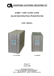
MANUAL BYPASS
- Manuale D’uso - User’s Manual -
ENGLISH
USER MANUAL
1 INTRODUCTION AND SAFETY
14 1.1 INTRODUCTION
14 1.2 PRECAUTIONS AND SAFETY RULES
14 2 PRESENTATION
15 2.1 OPERATING MODES
16 3 INSTALLATION
17 3.1 RACK VERSION
17 3.2 WALL VERSION (BOX)
18 3.3 INSTALLATION INSTRUCTIONS
19 3.4 CONNECTING THE BYPASS
20 4 USING THE BYPASS
21 4.1 INSTRUCTIONS TO BE FOLLOWED FOR UPS MAINTENANCE
21 4.2 BYPASS LIMITATIONS OF USE
21 5 TECHNICAL SPECIFICATIONS
22 13
1 INTRODUCTION AND SAFETY
1.1
Introduction
Thank you for choosing our product.
The manufacturer is particularly specialised in the development and manufacture of uninterruptible power
supplies (UPSs) and related accessories.
This manual contains detailed instructions for installing and using the BYPASS.
To get maximum performance from your device, please read and follow the instructions described herein.
Keep this manual close to the BYPASS.
© Reproduction, even partial, of any part of this manual is forbidden unless authorised by the manufacturer.
For improvement purposes, the manufacturer reserves the right to change the product described at any time
without notice.
1.2
Precautions and safety rules
This part of the manual contains the precautions to be followed closely as far as SAFETY is concerned.
a) The device must always be earthed during use. Do not remove the plug from the power supply as
this would disconnect the safety earth for all devices powered.
b) The BYPASS has HAZARDOUS electrical voltages inside it. Any maintenance must ONLY be
performed by trained personnel.
c) Do not connect the neutral output to the neutral input or to earth as this may damage the UPS
connected to the BYPASS itself.
d) The output outlets may be live even if the UPS is not connected to the mains.
e) Do not allow water, liquids in general and/or other foreign objects to get inside the BYPASS. Do not
expose the device to direct sunlight or heat sources.
f) The separable power cable is intended as a sectioning device. Be sure to leave adequate free space
near the cable connection for easy disconnection.
g) Observing the neutral and phase indications relating to plugs and outlets, the BYPASS inserted in a
system does not change the existing neutral system.
h) Do not connect the UPS to plugs or outlets other than the dedicated ones on the BYPASS. Incorrect
installation could cause malfunctions or failures of the UPS and the load connected to it.
14
2 PRESENTATION
The purpose of a BYPASS is to connect the load to the mains with minimal interruption to allow the
ordinary and extraordinary maintenance of the UPS.
The BYPASS makes it possible to switch the utilities connected to it onto the main power line in the event
that the UPS is switched off or becomes blocked.
The BYPASS is supplied for installation in rack cabinets or for installation on the wall or above the 10 or
16A UPS (BOX).
Box 10A
Box 16A
Rack
N.B. The plug/outlet configurations vary depending on the versions.
15
2.1
Operating modes
The BYPASS has a manual switch (SWITCH) with which you can choose the operating mode.
SWITCH
UPS
MAINS
UPS
BYPASS
RACK
UPS
MAINS
UPS
BYPASS
SWITCH
BOX 10A/16A
“UPS/BYPASS” SWITCH
SWITCH to select the load power supply from the UPS or mains (BYPASS position).
“MAINS” light (green) on
Mains present at the bypass input.
“UPS” light (green) on
UPS voltage present at the bypass input.
16
3 INSTALLATION
CAUTION: before performing the following sequence of operations, ensure that the UPS is completely
shut down and is not connected to the mains.
N.B. the installation of a 16A circuit breaker (curve C) upstream from the BYPASS is required. This
protection is necessary if required by the UPS user manual.
WARNING: observing the neutral (N) and phase (P) indications relating to plugs and outlets, the BYPASS
inserted in a system does not change the existing neutral system. The neutral system will still be modified if
an isolation transformer is present.
For versions with output cable: the blue wire identifies the neutral cable, while the yellow-green wire
identifies the earthing cable.
SOCKET
N
N
N
N
PLUGS
N
N
N
N
N
N
N
N
3.1
Rack version
With rack installation, the use of support brackets (L-shaped support guides) available at rack cabinet dealers
is recommended.
17
3.2
Wall version (BOX)
Attach the Bypass to the wall bracket as shown in the figure below, position the slotted L-bracket without
fully tightening the two screws.
The figure below shows the drilling template for installing the BYPASS on the wall.
18
Adjust the L-bracket on the slots to ensure the cables remain secured as shown in the figure.
3.3
Installation instructions
Before connecting the BYPASS to the UPS, ensure the following conditions are met:
1) Do not position in areas exposed to direct sunlight or hot air
2) Keep the ambient temperature between 0 °C and 40 °C
3) The relative humidity in the environment must not exceed 90%
4) Avoid dusty environments
19
3.4
Connecting the BYPASS
LOAD
MAINS INPUT
TO UPS INPUT
TO UPS OUTPUT
Rack version: rear view
TO UPS OUTPUT
TO UPS INPUT MAINS INPUT
TO UPS OUTPUT
LOAD
TO UPS INPUT MAINS INPUT
LOAD
10A Version
16A Version
N.B. The plug/outlet configurations vary depending on the versions.
1. Check that the SWITCH is in the “BYPASS” position
2. Connect the load to the output outlets (Load)
(N.B. The plug/outlet configurations vary depending on the versions)
3. Connect the UPS input to the outlet located on the BYPASS marked “TO UPS INPUT”
4. Connect the UPS input to the plug located on the BYPASS marked “TO UPS OUTPUT”
5. Connect the power cable to the plug marked “MAINS INPUT”
20
6. At this point the load is powered. Check that the “MAINS” (green) light is on. If it is not, check that
there are no switches open upstream from the BYPASS.
7. Turn on the UPS (follow the instructions in the UPS user manual).
8. Push the SWITCH to “UPS”. Check that the green light is on. If it is not, make sure that the UPS is
turned on and check all connections with it.
4 USING THE BYPASS
4.1
Instructions to be followed for UPS maintenance
Instructions to be followed when it is necessary to repair, replace or carry out maintenance on the UPS.
a.
b.
c.
d.
e.
f.
*
Move the SWITCH to the “BYPASS” position*
Turn off the UPS
Disconnect the UPS
Reconnect the UPS (new or repaired)
Turn on the UPS
Move the SWITCH to the “UPS” position
When the SWITCH is in the “MAINS” position, any disturbance of the mains affects the load powered
by the BYPASS. This means that in the event of a mains blackout, even if the UPS is on, the load is
disconnected.
4.2
BYPASS limitations of use
The BYPASS can power multiple loads at the same time, provided that the total current output is less than
16A for the Box 16A and Rack versions and 10A for the Box 10A version.
21
5 TECHNICAL SPECIFICATIONS
MODEL
Rated voltage
Switching time
Maximum current
Ambient temperature
Humidity
Protective devices
Dimensions H x W x D
Weight
BOX 10A
[Vac]
[ms]
[A]
[°C]
[mm]
[kg]
MODEL
Rated voltage
Switching time
Maximum current
Ambient temperature
Humidity
Protective devices
Dimensions H x W x D
Weight
BOX 16A
[Vac]
[ms]
[A]
[°C]
[mm]
[kg]
MODEL
Rated voltage
Switching time
Maximum current
Ambient temperature
Humidity
Protective devices
Dimensions H x W x D
Weight
220 / 230 / 240
typical: 3
maximum: 5
10
0 – 40
< 90% without condensation
overcurrent - short circuit
160 x 65 x 240
3.3
220 / 230 / 240
typical: 3
maximum: 5
16
0 – 40
< 90% without condensation
overcurrent - short circuit
160 x 65 x 240
3.3
RACK
[Vac]
[ms]
[A]
[°C]
[kg]
22
220 / 230 / 240
typical: 3
maximum: 5
16
0 – 40
< 90% without condensation
overcurrent - short circuit
44 (1U) x 440 x 215
6.8
- 0MNBYM10A2LUA -