1
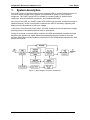
G-NET 1 KVA / 2 KVA / 3 KVA
ONLINE UNINTERRUPTIBLE POWER SYSTEM
USER MANUAL
2 / 3 KVA MODEL
1 kVA MODEL
Release 1.0
January 2008
Har Hotzvim Industrial Park,
14 Hartom St., P.O.B. 45029, Jerusalem 91450, Israel
Tel: 972-2-588-8222 Fax: 972-2-582-8875
Email: [email protected] Website: www.gamatronic.com
User Guide
Gamatronic Electronic Industries Ltd.
Gamatronic Electronic Industries Ltd.
Har Hotzvim Industrial Park
14 Hartom St.
PO Box 45029
Jerusalem 91450
Israel
Tel: +972-2-588-8222
Fax: +972-2-582-8875
Email: [email protected]
Website: www.gamatronic.com
The equipment described in this document is not intended for use in
connection with any application requiring fail-safe performance, such as
the operation of nuclear power facilities, air traffic control or
navigation systems, weapons control systems, life support systems, or any
other system whose failure could lead to injury, death, environmental
damage or mass destruction.
© Copyright 2008 by Gamatronic Electronic Industries Ltd.
All rights reserved worldwide.
The information contained in this document is proprietary and is subject to all relevant copyright, patent and other laws
protecting intellectual property, as well as any specific agreement protecting Gamatronic Electronic Industries Ltd. rights in the
aforesaid information. Neither this document nor the information contained herein may be published, reproduced or disclosed
to third parties, in whole or in part, without the express, prior, written permission of Gamatronic Electronic Industries Ltd. In
addition, any use of this document or the information contained herein for any purposes other than those for which it was
disclosed is strictly forbidden.
Gamatronic Electronic Industries Ltd. reserves the right, without prior notice or liability, to make changes in equipment design
or specifications.
Information supplied by Gamatronic Electronic Industries Ltd. is believed to be accurate and reliable. However, no
responsibility is assumed by Gamatronic Electronic Industries Ltd. for the use thereof nor for the rights of third parties which
may be affected in any way by the use thereof.
Any representation(s) in this document concerning performance of Gamatronic Electronic Industries Ltd. product(s) are for
informational purposes only and are not warranties of future performance, either express or implied. Gamatronic Electronic
Industries Ltd. standard limited warranty, stated in its sales contract or order confirmation form, is the only warranty offered by
Gamatronic Electronic Industries Ltd. in relation thereto.
This document may contain flaws, omissions or typesetting errors; no warranty is granted nor liability assumed in relation
thereto unless specifically undertaken in Gamatronic Electronic Industries Ltd. sales contract or order confirmation.
Information contained herein is periodically updated and changes will be incorporated into subsequent editions. If you have
encountered an error, please notify Gamatronic Electronic Industries Ltd. All specifications are subject to change without prior
notice.
ii
G-NET UPS User Manual
Gamatronic Electronic Industries Ltd.
User Guide
TABLE OF CONTENTS
1.
2.
3.
4.
5.
6.
7.
8.
9.
SYSTEM DESCRIPTION....................................................................................... 1
WHEN YOU RECEIVE YOUR UPS ....................................................................... 4
INSTALLING THE UPS ......................................................................................... 4
OPERATING INSTRUCTIONS .............................................................................. 5
4.1 Turning ON the UPS ................................................................................... 5
4.2 Turning OFF the UPS ................................................................................. 5
4.3 Performing a battery test ........................................................................... 5
CONTROL PANEL FEATURES ............................................................................ 6
5.1 Function buttons ........................................................................................ 6
5.2 LED indicators ............................................................................................ 6
5.3 Battery level and load level indicators ..................................................... 6
5.4 Battery level indicator ................................................................................ 7
REPLACING THE UPS BATTERIES .................................................................... 7
TROUBLESHOOTING........................................................................................... 8
AUTOMATED COMPUTER SHUTDOWN........................................................... 10
TECHNICAL SPECIFICATIONS ......................................................................... 11
LIST OF FIGURES
Figure 1:
Figure 2:
Figure 3:
Figure 4:
Figure 5:
Figure 6:
Block diagram of system architecture .................................................................. 1
The UPS control panel ............................................................................................ 2
G-NET 1 kVA rear panel .......................................................................................... 2
G-NET 2 kVA rear panel .......................................................................................... 3
Backup time vs. load, representative .................................................................... 3
Pin usage on RS232-D9 socket ............................................................................ 10
LIST OF TABLES
Table 1: LED indicators on the front panel ........................................................................... 6
Table 2: The LED column as a load-level indicator ............................................................... 7
Table 3: The LED column as a battery-charge indicator. .................................................... 7
Table 4: Pin usage on RS232-D9 socket.............................................................................. 10
Table 5: Technical Specifications ........................................................................................ 11
G-NET UPS User Manual
iii
User Guide
iv
Gamatronic Electronic Industries Ltd.
G-NET UPS User Manual
Gamatronic Electronic Industries Ltd.
1.
User Guide
System description
The G-NET series of Uninterruptible Power Supplies (UPS) is a line of advanced, true online UPSs which provide clean, reliable, and regulated AC power to your precision
equipment. The G-NET-series UPS is suitable as a power supply for loads such as
computers, telecommunication equipment, and computerized tools.
As a true on-line UPS, the G-NET-series UPS continuously provides conditioned power to
attached devices. Under normal power conditions the UPS is constantly regulating and
filtering out any fluctuations of the input voltage.
In the event of an electrical power failure, the UPS employs its internal batteries to supply
back-up power to the attached devices with no interruption.
During an overload or inverter failure condition, the UPS automatically transfers the load
devices to the bypass line, again without interrupting the supply of power to the load
devices. When the overload condition is cleared, the UPS automatically transfers the load
back to the inverter.
Figure 1: Block diagram of system architecture
G-NET UPS User Manual
System description
1
User Guide
Gamatronic Electronic Industries Ltd.
Figure 2: The UPS control panel
Figure 3: G-NET 1 kVA rear panel
2
System description
G-NET UPS User Manual
Gamatronic Electronic Industries Ltd.
User Guide
Figure 4: G-NET 2 kVA rear panel
Figure 5: Backup time vs. load, representative
G-NET UPS User Manual
System description
3
User Guide
2.
Gamatronic Electronic Industries Ltd.
When you receive your UPS
The G-NET UPS is delivered in a box to protect the UPS from damage. Before you open
the box, inspect the box to verify it is undamaged. If you note any damage to the box,
immediately notify the delivery firm.
Save the UPS carton; you may need it later.
Perform a visual inspection of the UPS. Notify your dealer immediately if you detect any
signs of damage to the UPS.
The UPS carton contains the following items:
•
The G-NET UPS.
•
The User Guide (this book).
•
Compact disc with software for automatic computer shutdown.
•
Communication cable.
•
Cable for connecting the UPS with the ac mains input.
3.
Installing the UPS
1.
Verify that the voltage and frequency of the ac power mains is appropriate for the UPS
(160 ~ 300 Vac, 50 Hz).
2.
Use the supplied cable to connect the UPS to the ac power mains. The connection on
the UPS for this cable is located on the rear panel and is labeled AC INPUT in Figure
3 (on page 2) and Figure 4 (on page 3).
Important notice: The UPS is delivered with the batteries uncharged. The batteries are
not able to provide backup until they have been charged. To charge the UPS batteries,
leave the UPS connected to the ac mains and with no load devices attached to the UPS,
for at least 8 hours.
It is permissible to use the UPS before the 8 hours of charging is complete. Just be aware
that if you do, the backup voltage (in the event of a power failure) will be shorter than
normal until the battery charging process has completed.
3.
Turn on the UPS by pressing the “ON” button on the front panel (see Figure 2 on page
2). Wait about 10 seconds until the “LINE” LED on the UPS front panel remains
steadily lit.
4.
Connect the computer or other load devices to the UPS rear panel, using the sockets
labeled “AC OUTPUT” in Figure 3 or Figure 4.
4
When you receive your UPS
G-NET UPS User Manual
Gamatronic Electronic Industries Ltd.
4.
4.1
User Guide
Operating instructions
TURNING ON THE UPS
To turn the UPS on, press the “ON” button on the UPS front panel (see Figure 2 on page
2). The ON button is labeled “|”. Wait about ten seconds until the “LINE” LED on the UPS
front panel remains steadily lit.
4.2
TURNING OFF THE UPS
To turn the UPS off, press the “OFF” button on the UPS front panel (see Figure 2 on page
2). The “OFF” button is labeled like this:
4.3
.
PERFORMING A BATTERY TEST
To test the UPS battery, when the UPS and the load devices connected to it are operating,
do the following:
1.
On the 2 kVA and 3kVA models, locate the rear panel line circuit breaker that is
situated on top of the ac line connection and turn it OFF.
On the 1 kVA model, locate the external circuit breaker that controls the ac mains feed
to the UPS and turn it OFF.
2.
For all models, an audible alarm (beep) will be heard about every four seconds, and
the orange LED labeled “BAT” on the front panel lights up. The lighting of the “BAT”
LED and the audible alarm indicate that the battery is supplying power to the load
devices.
3.
To end the test, turn ON the circuit breaker controlling the ac input to the UPS (the
same circuit breaker you turned off in step 1 above).
G-NET UPS User Manual
Operating instructions
5
User Guide
5.
Gamatronic Electronic Industries Ltd.
Control panel features
The UPS control panel on the front side of the UPS contains two function buttons and a
number of LED indicators.
5.1
FUNCTION BUTTONS
The button labeled “|” turns the UPS ON.
The button labeled
5.2
turns the UPS OFF.
LED INDICATORS
Table 1: LED indicators on the front panel
LED
NAME
FUNCTION
LINE
Lights when ac voltage is present at the UPS input.
BYPASS
When lit, indicates that the load is being supplied from the bypass voltage.
INVERTER
When lit, indicates that the UPS is supplying the load from the inverter
(normal operation) .
FAULT
Indicates a problem in the UPS’s operation.
5.3
BATTERY LEVEL AND LOAD LEVEL INDICATORS
The UPS front panel includes a column of 6 LEDs (see Figure 2 on page 2).
The uppermost of these LEDs is a red “CAUTION” indicator. In normal (inverter) mode,
when this CAUTION indicator lights it indicates an overload condition; the load on the UPS
should be reduced.
In battery mode, when the “CAUTION” LED lights it means the battery is almost exhausted.
Of the remaining five LEDs, four are green and one is orange. These five LEDs serve as a
load indicator when the UPS is in inverter mode, and as a battery charge indicator when
the UPS is in battery mode.
5.3.1
LOAD LEVEL INDICATOR
When the UPS is operating in inverter mode – that is, when it is receiving input power from
the ac mains – the column of five LEDs (4 green and 1 orange) serves as a load-level
indicator.
Table 2 explains how to interpret the LEDs in this situation.
6
Control panel features
G-NET UPS User Manual
Gamatronic Electronic Industries Ltd.
User Guide
Table 2: The LED column as a load-level indicator
NUMBER OF
LEDS LIT
RELATIVE LOAD LEVEL
1
0–30 %
12
31–50 %
123
51–70 %
1234
71–95 %
12345
96 %+ (overload)
COMMENT
The audible alarm beeps twice per second.
Turn off unnecessary load devices.
LEDs 1–4 are green.
LED 5 is orange.
5.4
BATTERY LEVEL INDICATOR
When the UPS is operating in battery mode – that is, there is no ac input to the UPS and it
is supplying power to the load from the battery – the audible alarm beeps about once every
four seconds and the column of five LEDs (4 green and 1 orange) serves as a battery-level
indicator, showing the relative amount of electrical energy remaining in the battery.
Table 3 below explains how to interpret the column of 5 LEDs in such a situation.
Table 3: The LED column as a battery-charge indicator.
NUMBER OF
LEDS LIT
RELATIVE LOAD LEVEL
12345
100 %
1234
76–99 %
123
51–75 %
12
26–50 %
1
0–25 %
COMMENT
Battery is fully charged
The battery is almost exhausted. The audible
alarm beeps once every four seconds.
LED 1 is orange.
LEDs 2–5 are green.
6.
Replacing the UPS batteries
The batteries supplied with your UPS are of optimum quality. Nonetheless, their lifetime is
limited. Battery lifetime depends on the number of charge/discharge cycles, average
battery load, environmental temperature, and other factors.
To replace the batteries of your UPS, contact your dealer or an authorized service
representative.
G-NET UPS User Manual
Replacing the UPS batteries
7
User Guide
7.
Gamatronic Electronic Industries Ltd.
Troubleshooting
Symptom
None of the LEDs on
the UPS front panel
light up.
The LINE LED does
not light and the
audible alarm is
beeping once every
four seconds.
Possible cause
Possible solution
The UPS is not
properly connected to
the ac mains or the
voltage or frequency of
the ac mains is not in a
range acceptable to
the UPS.
Verify that the UPS is properly
connected to the ac mains and that the
voltage and frequency of the ac mains
power is appropriate for your UPS.
The UPS’s ac line fuse
needs replacement.
Check the UPS’s line fuse. If it needs
replacement, replace it with a fuse of
the same type and rating.
You did not press the
ON button long
enough when turning
the UPS on.
To turn the UPS on it is necessary to
press and hold the ON button for at
lease 0.5 seconds.
The UPS is not
properly connected to
the ac mains or the
voltage or frequency of
the ac mains is not in a
range acceptable to
the UPS.
Verify that the UPS is properly
connected to the ac mains and that the
ac mains power is appropriate for your
UPS model in terms of voltage and
frequency.
The UPS’s ac line fuse
needs replacement.
Check the UPS’s line fuse. If it needs
replacement, replace it with a fuse of
the same type and rating.
The external circuit
breaker for the ac line
is in the OFF position.
Turn the external circuit breaker on the
UPSs ac supply line ON.
Turn off unneeded load devices to
reduce the load on the battery.
The red CAUTION
LED is lit and the
audible alarm beeps
continuously.
The battery is
overloaded, or the
battery charge is
insufficient for the load.
The batteries need
charging.
The backup time
provided by the UPS is
shorter than expected.
The batteries are
defective or need
replacement.
The UPSs battery
charger is defective.
8
Troubleshooting
Charge the battery.
Contact your dealer or an authorized
service technician. The batteries may
need replacement.
Charge the batteries by leaving the
UPS connected to the ac mains with
no load for 8 hours. Then perform a
battery test as described in section 4.3
on page 5. If the backup time is still
too short, contact your dealer or an
authorized service technician.
G-NET UPS User Manual
Gamatronic Electronic Industries Ltd.
Symptom
All of the load-level
LEDs are lit and the
audible alarm is
beeping twice per
second.
The UPS operates
normally, but the
“BAT” LED flashes and
the audible alarm
beeps steadily.
Possible cause
The UPS is
overloaded.
Battery voltage is low.
Battery voltage is
higher than the
charging voltage.
User Guide
Possible solution
Reduce the load on the UPS by
turning off some of the load devices.
Charge the batteries by leaving the
UPS connected to the ac mains with
no load for 8 hours. If this does not
eliminate the symptoms, contact your
dealer or an authorized service
technician.
There is not output
voltage and the
audible alarm beeps
steadily.
The load is shortcircuited.
Check all of the load devices for shortcircuit.
The UPS is not
working, the “LINE”
LED flashes, and the
audible alarm sounds
steadily.
The ac input voltage is
too high or two low.
Connect a transformer between the
UPS and the ac mains.
The “LINE” LED
flashes continuously.
The Phase and Neutral
input wires are
reversed.
Reverse the ac input Phase and
Neutral connections.
The “BAT” and LINE”
LEDs are lit.
The voltage and/or
frequency of the ac
input are out of range.
Connect a transformer between the
UPS and the ac mains.
The “BAT” LED is lit
and the audible alarm
beeps twice per
second.
The battery is almost
completely discharged.
Turn off the UPS before the battery
becomes completely discharged.
G-NET UPS User Manual
Troubleshooting
9
User Guide
8.
Gamatronic Electronic Industries Ltd.
Automated computer shutdown
A compact disk (CD ROM) is delivered along with the UPS. The disk contains software that
can be installed on a computer. If that computer is connected to the UPS, then, the
software can be used to perform an automatic, orderly shutdown of the computer in the
event of an ac power outage.
1.
Connect one end of the supplied D9 – D9 cable to the rear panel of the UPS, and
connect the other end to the computer. The D9 socket is shaped like this:
.
2.
Insert the supplied compact disk into the computer. The installation program on the
disk begins execution automatically. Follow the instructions on the computer screen to
complete the installation of the software.
3.
Simulate an ac power failure and verify that the software automatically shuts down the
computer after the specified time interval.
If technical support is required, this can be obtained by contacting your dealer or authorized
service representative.
The diagram below shows the pin usage for the RS232-D9 socket.
Table 4: Pin usage on RS232-D9 socket
Pin #
Function
I/O
2
RS232 Rx
Input
3
RS232 Tx
Output
5
Ground
Figure 6: Pin usage on RS232-D9 socket
10
Automated computer shutdown
G-NET UPS User Manual
Gamatronic Electronic Industries Ltd.
9.
User Guide
Technical Specifications
Table 5: Technical Specifications
G-NET MODEL
1K
1KS
2K
2KS
3K
3KS
INPUT
Voltage (Vac)
160 – 300, single phase, ground connection required
Maximum current (A)
7
12
Frequency (Hz)
16
50, ±5 %
Protection
Circuit breaker
Power factor (PF)
As per EN60555-2
OUTPUT
Voltage (Vac)
220, ±3 %
Frequency (Hz)
50, ±0.5 %
Power factor (PF)
0.9
Waveform
Power (kVA, kW)
Sinusoid
1 kVA, 700 W
2 kVA, 1400 W
Frequency deviation:
- In battery mode or when input frequency
deviates more than 5 %:
- At normal input frequency:
3 kVA, 2100 W
±5 %
<±5 %
Distortion:
- At full load (linear)
<3 % THD
- At full load (non-linear)
<6 % THD
Inverter efficiency at 100% load (%)
92
Overload tolerance
105 % : 60 sec.; 120 % : 5 sec.
Overload protection
140 % : 200 msec; 150 % : 10 msec.
Ratio max. / normal load
3:1
Transfer times (msec.)
- To battery
- To bypass (characteristic) / (maximum)
0
2.5 / 4
OPERATING ENVIRONMENT
Temperature (°C)
0–40 (32–104 °F)
Humidity (%)
20–90 (non-condensing)
Altitude
<1500 m without derating
Storage temperature (°C)
-15 to +40 (5–104 °F)
EN50081-1 / EN55022 Class B
EN50082-1 / IEC801-2 Level 2
Standards:
IEC801-3 Level 3
IEC801-4 Level 4
IEC801-5 Level 2
BATTERIES
Type
Voltage
Sealed, lead-acid, maintenance free. 12 V 7 Ah per cell
36 V (3 cells)
96 V (8 cells)
COMMUNICATION
RS232
D9 socket connection
DIMENSIONS
H x W x D (cm)
22 x 14.5 x 40.5
Weight (kg)
14.5
G-NET UPS User Manual
9
33 x 19.5 x 45.5
34
17
Technical Specifications
34
17
11