1
CLIMB-I T
CONTROL
U-TURN
2004 U S E R M A N UA L
SRAM CORPORATION • 2004 PSYLO USER MANUAL
ENGLISH
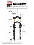
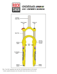
NOTE: YOUR FORK’S APPEARANCE MAY VARY FROM THE ILLUSTRATIONS/PHOTOS IN THIS MANUAL.
FOR THE LATEST INFORMATION ABOUT YOUR FORK VISIT OUR WEBSITE AT WWW.ROCKSHOX.COM.
SRAM CORPORATION • APRIL 2003
3
SRAM CORPORATION • 2004 PSYLO USER MANUAL
ENGLISH
Congratulations! You have the best in suspension components on your bicycle! This
manual contains important information about the safe operation and maintenance of your
fork. To ensure that your RockShox fork performs properly, we recommend that you have
your fork installed by a qualified bicycle mechanic. We also urge you to follow our
recommendations to help make your riding experience more enjoyable and trouble-free.
I
M
P
O
R
T A
N
T
Consumer Safety Information
1. The fork on your bicycle is designed for use by a single rider, on mountain
trails, and similar off-road conditions.
2. Before riding the bicycle, be sure the brakes are properly installed and
adjusted. If the brakes do not work properly, the rider could suffer serious
and/or fatal injuries.
3. Your fork may fail in certain circumstances, including, but not limited to,
any condition that causes a loss of oil; collision or other activity bending or
breaking the fork’s components or parts; and extended periods of non-use.
Fork failure may not be visible. Do not ride the bicycle if you notice bent or
broken fork parts, loss of oil, sounds of excessive topping out, or other
indications of a possible fork failure, such as loss of shock absorbing
properties. Instead, take your bike to a qualified dealer for inspection and
repair. In the event of a fork failure, damage to the bicycle or personal
injury may result.
4. Always use genuine RockShox parts. Use of aftermarket replacement parts
voids the warranty and could cause structural failure to the shock.
Structural failure could result in loss of control of the bicycle with possible
serious and/or fatal injuries.
5. Use extreme caution not to tilt the bicycle to either side when mounting the
bicycle to a carrier by the fork drop-outs (front wheel removed). The fork
legs may suffer structural damage if the bicycle is tilted while the drop-outs
are in the carrier. Make sure the fork is securely fastened down with a
quick release. Make sure the rear wheel is fastened down when using
ANY bike carrier that secures the fork s drop-outs. Not securing the rear
can allow the bike s mass to side-load the drop-outs, causing them to
break or crack. If the bicycle tilts or falls out of its carrier, do not ride the
bicycle until the fork is properly examined for possible damage. Return the
fork to your dealer for inspection or call RockShox if there is any question
of possible damage (See the International Distributor List). A fork leg or
drop-out failure could result in loss of control of the bicycle with possible
serious and/or fatal injuries.
6. Only mount cantilever-type brakes to the existing brake posts. Forks with
hangerless style braces are only designed for V - style or hydraulic
cantilever brakes. Do not use any cantilever brake other than those
intended by the brake manufacturer to work with a hangerless brace. Do
not route the front brake cable and/or cable housing through the stem or
any other mounts or cable stops. Do not use a front brake cable leverage
device mounted to the brace.
7. Observe all owner’s manual instructions for care and service of this product.
ROCKSHOX FORKS ARE DESIGNED FOR COMPETITIVE OFF-ROAD
RIDING AND DO NOT COME WITH THE PROPER REFLECTORS FOR ONROAD USE. YOUR DEALER SHOULD INSTALL PROPER REFLECTORS
TO MEET THE CONSUMER PRODUCT SAFETY COMMISSION S (CPSC)
REQUIREMENTS FOR BICYCLE STANDARDS IF THE FORK IS GOING TO
BE USED ON PUBLIC ROADS AT ANY TIME.
4
954-307864-000, REV. A
SRAM CORPORATION • 2004 PSYLO USER MANUAL
ENGLISH
INSTALLATION
It is extremely important that your RockShox fork is installed correctly by a qualified bicycle
mechanic. Improperly installed forks are extremely dangerous and can result in severe and/or
fatal injuries.
1.
Remove the existing fork from the bicycle and the crown race from the fork. Measure the length of the
fork steerer tube against the length of the RockShox steerer tube. The RockShox steerer tube may need
cutting to the proper length. Make sure there is sufficient length to clamp the stem (refer to the stem
manufacturer's instructions).
! WARNING
DO NOT ADD THREADS TO ROCKSHOX THREADLESS STEERERS. THE
STEERER TUBE CROWN ASSEMBLY IS A ONE-TIME PRESS FIT.
REPLACEMENT OF THE ASSEMBLY MUST BE DONE TO CHANGE THE
LENGTH, DIAMETER OR HEADSET TYPE (THREADED OR
THREADLESS).
DO NOT REMOVE OR REPLACE THE STEERER TUBE. THIS COULD
RESULT IN THE LOSS OF CONTROL OF THE BICYCLE WITH POSSIBLE
SERIOUS AND/OR FATAL INJURIES.
2.
3.
4.
5.
Install the headset crown race (29.9mm for 1 1/8" steerers) firmly against the top of the fork crown.
Install the fork assembly on the bike. Adjust the headset until you feel no play or drag.
Install the brakes according to the manufacturer's instructions and adjust brake pads properly. Use the
fork only with V-type or hydraulic cantilever brakes mounted to the existing brake posts or disc style
brakes mounted through the provided mounting holes. Do not use any cantilever brake other than
those intended by the brake manufacturer to work with a hangerless brace.
Adjust the front wheel quick release to clear the dropout's counter bore. The quick release nut must be
tightened after the wheel is properly seated into the dropout's counter bore. Make sure four or more
threads are engaged in the quick release nut when it is closed. Orient the quick release lever in front of
and parallel to the lower tube in the locked position.
Keep in mind tire clearance as you choose tires. Maximum size is 2.7" wide or 696 mm diameter installed.
Be sure to check this diameter whenever you change tires. To do this, remove the top caps and spring stack
assemblies and compress the fork completely to make sure at least 5 mm of clearance exists between the
top of the tire and the bottom of the crown. Exceeding maximum tire size will cause the tire to jam against
the crown when the fork is fully compressed.
PERFORMANCE TUNING
RockShox Psylo forks can be tuned for your particular weight, riding style, and terrain.
Checking Sag
Psylo forks are designed to sag when you are sitting on your bike. Sag is the compression of
the fork caused by the rider's weight. Proper sag allows the front wheel to follow the contour
of the terrain as you ride.
To measure sag, set the fork to maximum travel (125 mm). Install a zip tie on the upper tube
of the fork flush against the wiper seal. Sit on the bike with normal riding apparel. Step off
the bike, and measure the distance between the wiper seal and the zip tie. This is your sag.
The sag should be between 15 and 25 (19 to 31 mm) percent of maximum travel. If you're
unable to achieve optimum sag you may need to change the fork's spring.
Changing the Spring Rate
Spring rate is the amount of force needed to compress a spring one inch. Changing your Psylo
fork's coil spring for a spring of a higher or lower rate will alter the overall feel of your fork.
Higher spring rates make the fork feel more "stiff", while lower spring rates make the fork
more "supple". Contact your local RockShox dealer to order replacement springs.
SRAM CORPORATION • APRIL 2003
5
SRAM CORPORATION • 2004 PSYLO USER MANUAL
ENGLISH
NOTE: WHEN DECREASING TRAVEL (SEE “U-TURN TRAVEL ADJUST”), YOU INCREASE THE SPRING RATE.
E x t e r n a l R e b o u n d A d j u st m e n t ( R a ce , S L a n d XC m o d e l s )
Rebound damping controls the speed at which a fork returns to its full extension following
compression. Located at the bottom of the right fork leg is the rebound adjuster knob. Turning
the adjuster in the direction indicated by the "rabbit" on the rebound speed decal decreases
rebound damping, causing the fork to return to full extension faster. Turning the adjuster in the
direction indicated by the "turtle" increases rebound damping, slowing the return of the fork to
full extension.
Excessive rebound damping will cause the fork to "pack up" over successive bumps, reducing
travel and causing the fork to bottom out. Set your fork to rebound as fast as possible without
"topping out" or kicking back. This allows your fork to follow the contours of the trail,
maximizing stability, traction and control.
XC ONLY: The knob offers 90 degrees of adjustment.
RACE AND SL: The knob offers three complete turns of adjustment.
U - t u r n Tr a ve l A d j u st
IMPORTANT: DO NOT ADJUST THE U-TURN SYSTEM WHEN THE FORK IS LOCKED OUT. ADJUSTING THE U-TURN
WHILE THE FORK IS IN THE LOCKED POSITION MAY CAUSE DAMAGE TO THE SYSTEM.
Psylo U-turn forks can be adjusted from 80 to 125 mm of travel. To determine the travel on your
fork, use the travel gradients on the upper tube. Compare this measurement to the chart below.
C h a n g i n g Tr a ve l
Turning the U-turn adjuster knob counterclockwise increases travel. From minimum travel,
there are approximately six turns to achieve maximum travel (125 mm). Each turn increases or
decreases the travel by 7.5 mm (fig. 1).
IMPORTANT: STOP TURNING THE U-TURN ADJUSTER KNOB AFTER YOU’VE REACH 125 MM OF TRAVEL
(MAXIMUM TRAVEL). TURNING THE KNOB PAST THIS POINT MAY CAUSE DAMAGE TO THE U-TURN FEATURE.
% Increase of Spring Rate
Spring Rate Increase
30.0%
25.0%
20.0%
15.0%
10.0%
5.0%
0.0%
125
117.5
110
102.5
95
87.5
80
U-Turn Travel Adjustment (mm)
Fig. 1
6
954-307864-000, REV. A
SRAM CORPORATION • 2004 PSYLO USER MANUAL
PURE SYSTEM (SL
ENGLISH
AND
RACE)
Your fork uses the Pure Damping System. This system provides maximum ride control,
allowing the rider to smooth out the bumps, with on-the-fly adjustable compression damping
(including lockout for climbing).
C l i m b - I t C o n t ro l Pe r fo r m a n ce ( S L )
To change the compression damping adjustment on your fork, locate the adjuster knob on the
top of the right leg. A clockwise adjustment increases the compression damping. Turning the
adjuster completely clockwise provides on-the-fly lockout to minimize movement while
sprinting or climbing. Integrated into the lockout system is a big-hit blow-off feature, allowing
fork movement in the event of an unexpected change in terrain.
To maintain lockout control and damping quality, the Pure Damping system should be rebuilt
once a year. We recommend that a qualified bicycle mechanic with proper tools should rebuild
the Pure Damping System. For more detailed service information, contact your local RockShox
dealer or visit www.rockshox.com.
R e m o t e L o c k o u t ( R a ce )
The Remote Lockout lever allows incremental compression
adjustment and lockout of your fork without removal of your hands
from the handlebars. The lever offers approximately 130 degrees of
adjustment from fully active to the lockout position. In the center of
the Remote Lockout lever is the "go" button. Depress the "go"
button to return your fork to the active position.
MOUNTING
The Remote Lockout is mounted on the left-hand side of the
handlebar. With separate brake lever and shifter setups, mount the
Remote Lockout between the brake lever and shifter (fig. 1).
With integrated designs, mount the Remote Lockout outboard
or inboard (fig. 2) of the brake lever-shifter setup.
Fig. 1
SETUP
1.
2.
3.
4.
5.
6.
Clamp the Remote Lockout lever in the appropriate mounting
orientation (see fig 1 and 2). Torque to 8 in-lb.
Depress the “go” button and rotate the lever to the open position.
Feed the housing into the remote clamp and route the cable.
Orient the Remote Cap 60 degrees counterclockwise from the
timing mark (fig. 3). This is the default open position. For a stiffer
feeling fork, rotate the remote cap less than 60 degrees from the
default “open” position.
Tighten the remote clamp screw and torque to 8 in-lb (fig. 3).
Ensure proper function of the Remote Lockout by activating and
deactivating the lockout
Fig. 2
NOTE: THE CABLE IS TEFLON COATED.
Fig. 3
SRAM CORPORATION • APRIL 2003
7
SRAM CORPORATION • 2004 PSYLO USER MANUAL
ENGLISH
TULLIO QUICK RELEASE (SOME
MODELS)
I M P O R T A N T
Consumer Safety Information
The Tullio Quick Release system allows the use of a standard 20 mm X 110
mm thru-axle hub for enhanced stiffness. The axle threads into the left fork leg,
tightening the hub against the left drop out. The axle is clamped in place in the
lower casting by the Tullio Quick Release levers. Check with your hub
manufacturer for compatibility, then follow the steps below.
Riding with an improperly installed wheel can allow the wheel to move or
disengage from the bicycle, causing damage to the bicycle, and serious injury
or death to the rider. It is essential that that you:
• Ensure that your axle, dropouts, and quick release mechanisms are clean
and free of dirt or debris.
• Ask your dealer to help you understand how to properly secure your front
wheel using the Tullio Quick Release System
• Apply the correct techniques when installing your front wheel.
• Never ride your bicycle unless you are sure the front wheel is installed
properly and secure.
I n st a l l a t i o n
If using a rim brake, you may need to open the brake shoes. If you are unfamiliar with opening
your brake, see your brake manufacturer’s instructions.
1.
2.
Open the left and right dropouts by pulling downward on the fork’s quick release levers.
Position your wheel in the dropouts of the lower leg. The hub should seat firmly in the dropouts.
If using a disc brake, be sure to position the rotor in the caliper. Verify that neither the rotor,
hub, nor rotor bolts interfere with the lower legs. If unfamiliar with adjusting your disc brake,
see your brake manufacturer’s instructions.
Tighten
1.
2.
3.
Slide the axle through the right side of the hub until it engages the threads of the left drop out.
Gently pull on the axle fixing lever to remove it from the axle. Rotate the lever 90 degrees until it is
perpendicular to the axle.
To tighten the axle into the dropout, turn the axle fixing lever clockwise until the left side of the axle is
flush with the outside face of the left dropout.
NOTE : HAND TIGHTEN THE AXLE INTO THE LOWER CASTING. NEVER USE ANY OTHER TOOL TO TIGHTEN THE
AXLE INTO THE LOWER LEG. OVER-TIGHTENING OF THE AXLE CAN DAMAGE THE AXLE AND/OR THE LOWER LEG.
S e c u re
1.
2.
3.
8
Close the dropouts by pushing the fork’s left and right quick release levers towards the lower legs.
The quick release mechanism is an “over-center cam”, similar to the quick release found on many
bicycle wheels. When closing the dropouts, tension should be felt when the quick release lever is in the
horizontal position (90 degrees to the lower leg), and the quick release lever should leave an imprint in
the palm of your hand. If resistance is not felt at the 90 degree position and if the lever does not leave
a clear imprint in the palm of your hand, tension is insufficient. To increase tension, open the quick
release lever and using a 3 mm hex wrench, turn the quick release retaining screw in small increments
until proper tension is felt.
Verify that the axle is unable to spin or move in the dropout by grasping the axle lever and turning
counter clockwise.
954-307864-000, REV. A
SRAM CORPORATION • 2004 PSYLO USER MANUAL
ENGLISH
! WA R N ING
DIRT AND DEBRIS CAN ACCUMULATE BETWEEN THE DROPOUT
OPENINGS. ALWAYS CHECK AND CLEAN THIS AREA WHEN
REINSTALLING THE WHEEL. ACCUMULATED DIRT AND DEBRIS CAN
COMPROMISE THE SECURITY OF THE AXLE, LEADING TO SERIOUS
AND/OR FATAL INJURY.
4.
Re-install the axle lever into the axle.
NOTE: REMOVAL AND INSTALLATION OF THE FRONT WHEEL CAN AFFECT BRAKE PERFORMANCE. FOLLOWING
WHEEL INSTALLATION, ALWAYS CHECK YOUR BRAKES IN A FLAT AREA, AWAY FROM TRAFFIC, OBSTACLE, OR
OTHER HAZARDS.
MAINTENANCE
Psylo Model
Ev
ery
Rid
e
25
Ho
urs
50
Ho
urs
10
0H
ou
rs
20
0H
ou
rs
To maintain the high performance, safety, and long life of your fork, periodic maintenance is
required. If you ride in extreme conditions, maintenance should be performed more frequently.
Maintenance
All
Clean dirt and debris from upper tubes
All
Check upper tubes for scratches
Check top caps, brake posts and shaft bolts for
proper torque
All
All
Lubricate foam ring
Remove lower casting, clean bushings and
change oil bath
All
*
*
SL and Race Change oil in pure system
Race
Clean and lubricate Remote Lockout assembly
All
Clean and lubricate U-Turn spring assembly
*
*
*
SL and Race Rebuild Pure System
*
WE
RECOMMEND THIS SERVICE BE PERFORMED BY A QUALIFIED BICYCLE MECHANIC.
TO
OBTAIN
SERVICE INFORMATION OR INSTRUCTIONS, VISIT OUR WEBSITE AT WWW.ROCKSHOX.COM OR CONTACT
YOUR LOCAL
ROCKSHOX DEALER OR DISTRIBUTOR.
Torque Tightening Values
Top Caps
Brake Posts
Shaft Bolts
Remote Lockout clamp bolt
Remote clamp screw
Pure top cap clamp screw
Climb-it/U-Turn knob ascrew
SRAM CORPORATION • APRIL 2003
65 in-lb
80 in-lb
60 in-lb
8 in-lb
8 in-lb
12 in-lb
12 in-lb
9
SRAM CORPORATION • 2004 PSYLO USER MANUAL
ENGLISH
WARRANTY
SRAM Corporation warrants its products for a period of two years from original date of
purchase to be free from defects in materials or workmanship. SRAM, or an authorized SRAM
Agent must inspect all SRAM products. If a product is found by SRAM or its authorized agent
to be defective in materials or workmanship, replacement or repair is at the option of SRAM.
This warranty is the sole and exclusive remedy. SRAM shall not be held liable for any indirect,
special, or consequential damages.
E xc l u s i o n s o f Wa r ra n t y
This warranty does not apply to products which have not been properly installed and adjusted
according to RockShox installation instructions. The warranty does not cover any product that
has been subject to misuse or whose serial number has been altered, defaced or removed. This
warranty does not apply to damage to the product caused by a crash, impact, abuse of the
product, non-compliance with manufacturer's specifications, or any other circumstances in
which the product has been subjected to forces or loads beyond its design. This warranty does
not cover paint damage or modifications to the product.
Original proof of purchase is required. Warranty repair/replacement is only valid upon
presentation of proof of purchase, directly submitted to SRAM at the time of warranty
evaluation. Warranty repair or replacement is at the discretion of SRAM or its authorized
agent, upon physical product evaluation and proof of purchase.
This warranty does not include or cover common 'wear and tear' parts which are subject to
damage as a result of normal use, failure to service product according to SRAM
recommendations, wet conditions, racing, use of disc brakes, rider weight, riding or installation
in conditions or applications other than recommended.
'Wear and Tear' parts are identified as: External dust seals, bushings, foam rings, rubber
moving parts (such as air sealing o-rings and glide rings), stripped threaded shafts or bolts,
upper tubes (stanchions), rear shock mounting hardware and springs, and fork drop outs.
P i o n e e r S u p p o r t P ro g ra m
In the event parts are unavailable at the time of your repair, at the option of SRAM or its
authorized agent, a replacement fork may be provided at a determined discount price.
Wa r ra n t y E x p e n s e s I n c u r re d
The SRAM warranty policy excludes expenses incurred as a result of transportation of product
from a SRAM dealer to SRAM, or its authorized distributor, labor performed by a SRAM dealer
for removal of RockShox product, or warranty repair work performed by a SRAM dealer.
Warranty work performed by a SRAM dealer is voluntary.
Wa r ra n t y R e p a i r
If for any reason it should be necessary to have warranty work done, return the product to a SRAM
dealer. In the USA, dealers are required to call for a Return Authorization number (RA#) prior to
returning product. Outside the USA, dealers are required to call an authorized SRAM Distributor.
For more technical information, visit our website at www.rockshox.com. Dealers outside the USA must
contact their local distributor. For a complete list of Authorized Distributors outside the USA, visit
www.rockshox.com.
10
954-307864-000, REV. A