1
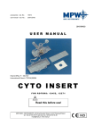
USER MANUAL KAB MAGNETIC FILTER 2012 05 Installation and Maintenance Manual KAB Doc. ref.: NIE KAB 20010 08 Rev.: A Date: 26/08/2010 CONTENTS 1 DESCRIPTION. . . . . . . . . . . . . . . . . . . . . . . . . . . . . . . . . . . . . . . . p.03 2 OPERATING PRINCIPLE . . . . . . . . . . . . . . . . . . . . . . . . . . . . . . . . . . p.03 3 INSTALLATION - . . . . . . . . . . . . . . . . . . . . . . . . . . . . . . . . . . . . . p.04 4 COMMISSIONING . . . . . . . . . . . . . . . . . . . . . . . . . . . . . . . . . . . . . p.04 5 KAB CHARACTERISTICS . . . . . . . . . . . . . . . . . . . . . . . . . . . . . . . . p.05 6 MAINTENANCE . . . . . . . . . . . . . . . . . . . . . . . . . . . . . . . . . . . . . . p.06 7 DRAWINGS . . . . . . . . . . . . . . . . . . . . . . . . . . . . . . . . . . . . . . . . p.06 2 Installation and Maintenance Manual KAB Doc. ref.: NIE KAB 20010 08 Rev.: A Date: 26/08/2010 1. DESCRIPTION The KAB anti-sludge filter is a system designed to eliminate products resulting from corrosion of heating and airconditioning installations, and in particular iron oxide (Fe3O4). It can be used both for new installations and installations connected to old networks. These networks are of various types: Primary circuit connected to a boiler or dam exchanger type generator Primary storage of water heated by thermal solar collectors Other potential primary sources This filter comprises: A cover removable at the top with air vent valve A water inlet to be treated at the top, with flange connection 1 monobloc cylindrical body Multiple field magnetic stirring bars vertically suspended by a basket removable inside the device A filtered water outlet at the bottom, with flange connection 2. OPERATING PRINCIPLE Iron oxide is easy to identify in an installation. It takes the form of black sludge, consists of solubilised iron, and is precipitated in hydroxide. Hydroxide releases its hydrogen and is converted into magnetisable oxide, Fe3O4, known as magnetite. The size of this product (0.5µm) and its density do not allow efficient decantation or centrifugation. The KAB will use magnets to remove these magnetisable solid particles. Operating procedure: The circuit water to be treated is channelled on a set of multiple field magnetic stirring bars. Low flow speed and laminar flow conditions ensure retention of 99.9% of magnetisable particles of less than 0.5 micron. An agglomerate is then formed, and is deposited on the bars, which then trap non-magnetic particles thanks to their arrangement according to fields around bars. The results are installation cleaning and clear water circulation. We strongly recommend that you use the KAB concept for parallel operation of the primary flow rate up to 20% of nominal flow rate. Refer to the connection diagram for more details. Advantages: - Easy implementation - Compact dimensions - Cleaning simplified by wiping the magnetic stirring bars - Avoid network bleeds, thus allowing savings in new water supply - Can act as an injection chamber - Can be used in addition to a chemical treatment 3 Installation and Maintenance Manual KAB Doc. ref.: NIE KAB 20010 08 Rev.: A Date: 26/08/2010 3. INSTALLATION We recommend that you connect the KAB in parallel with the main flow rate. Flow rate in the system will be between 20 and 25% of circuit nominal flow rate. Incoming water to be treated will be via the TOP of the device, while the outgoing water will be at the BOTTOM. 4 Installation and Maintenance Manual KAB Doc. ref.: NIE KAB 20010 08 Rev.: A Date: 26/08/2010 4. COMMISSIONING Connect the KAB, complying with the inlet (top) and the outlet of the fluid to be treated. If necessary, install and connect electrically the circulating pump (optional), ensuring that you install the required electrical protection devices upstream Open the shut-off valve at the inlet side, and wait for KAB air bleed Open the shut-off valve on the outlet side Adjust the control valve so as to allow circulation in the KAB circuit of only a flow rate from 20 to 30% of total flow rate Q. When using the KAB for the first time, it is possible to use 30% of installation nominal flow rate (noted Q on the block diagram), with periodical cleaning of the magnetic stirring bars. When cleaning frequency is less regular (a large percentage of system water volume has been treated), treatment flow rate could be lowered to approximately 20% of nominal flow rate. When introducing treatment products, de-energise the treatment pump (if any), isolate the KAB using the 2 valves, and bleed to lower pressure and empty the top part of the cylinder. Then open the top cover and pour in the additive(s). Then screw back on the cover, open the valve on the inlet side to bleed air, fill with water, and pressurise. Then open the valve on the outlet side, and re-energise the treatment pump if there is one present. 5. KAB CHARACTERISTICS Type Install P Networ k vol. Number of housings (kW) (m3) KAB 03 350 KAB 07 P Capt a. (mCE) (kg) 1’’ 1 0.6 2 DN65 1 1.2 15 4 DN65 1 2.4 25 5 DN65 1 4.2 Flow rate in KAB (m3/h) Number of bars F3/F4 Flow rate to treat m3/h 5 60 15 3 1 820 10 130 35 7 KAB 15 1750 25 250 75 KAB 25 3000 40 375 125 5 DN Installation and Maintenance Manual KAB Doc. ref.: NIE KAB 20010 08 Rev.: A Date: 26/08/2010 6. MAINTENANCE When dirt builds up in the KAB, the pressure difference read on the top and bottom pressure gauges increases, as does also the pressure drop. If this is the case, and if pressure drop exceeds 5mCE (0.5 bar or 50 kPa), the KAB should be disassembled as follows: Flush quickly by opening and closing the drainage valve at the bottom If the device is equipped with a pump, cut its electricity supply Isolate the KAB from the rest of the installation by closing the shut-off valves at the device inlet and outlet Open the bottom drainage valve to depressurise and drain off the water in the KAB Unscrew the top flange by removing all the bolts Remove and clean the magnetic stirring bar(s), taking care to remove any magnetised metal particles Clean the filter basket with clear water Remove and clean the inside of the body. Once all the parts have been cleaned, reassemble in reverse order to the disassembly process described above: put back the parts in the KAB, close the drainage valve, close the top part, open the shut-off valves at the device inlet and outlet, and restart the pump if necessary. Pressure read-out on both pressure gauges must be virtually identical. 7. DRAWINGS See the following pages. 6 Installation and Maintenance Manual KAB Doc. ref.: NIE KAB 20010 08 Rev.: A Date: 26/08/2010 A B C D E F G H 8 8 Ø220 7 7 DN25 6 700 800 450 Ø114.3 5 200 200 DN25 70 4 3 2 2 1 1 H G F E D ASSEMBLY WITHOUT OPTION 7 C B A Installation and Maintenance Manual KAB OPTION CODE: PUMP/VALVE OPTION ASSEMBLY 8 Doc. ref.: NIE KAB 20010 08 Rev.: A Date: 26/08/2010 Installation and Maintenance Manual KAB Doc. ref.: NIE KAB 20010 08 Rev.: A Date: 26/08/2010 A B C D E F G H 8 8 DN65 7 7 Ø245 915 608 6 6 5 50 200 DN65 4 3 2 2 393 1 1 H G F E D ASSEMBLY WITHOUT OPTION 9 C B A Installation and Maintenance Manual KAB Doc. ref.: NIE KAB 20010 08 Rev.: A Date: 26/08/2010 A B C D E F G H 8 8 7 7 DN65 5 Ø245 915 608 6 DN32 50 200 5 4 3 759.5 2 2 CODE OPTION: KABPOMVAN07 1 1 H G F E D OPTION CODE: PUMP/VALVE OPTION ASSEMBLY 10 C B A Doc. ref.: NIE KAB 20010 08 Rev.: A Date: 26/08/2010 Installation and Maintenance Manual KAB A B C D E F G H 8 7 8 2+3 6 DN65 7 7 5 Ø245 915 608 6 6 5 DN65 50 200 1 4 4 3 2 2 1 1 H G F E D ASSEMBLY WITHOUT OPTION 11 C B A Installation and Maintenance Manual KAB PUMP/VALVE OPTION ASSEMBLY 12 Doc. ref.: NIE KAB 20010 08 Rev.: A Date: 26/08/2010 Installation and Maintenance Manual KAB Doc. ref.: NIE KAB 20010 08 Rev.: A Date: 26/08/2010 A B C D E F G H 8 8 Ø340 DN65 7 7 750 6 1077 Ø245 5 DN65 1 50 200 4 3 2 2 393 1 1 H G F E D ASSEMBLY WITHOUT OPTION 13 C B A Installation and Maintenance Manual KAB PUMP/VALVE OPTION ASSEMBLY 14 Doc. ref.: NIE KAB 20010 08 Rev.: A Date: 26/08/2010