1
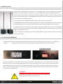
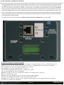
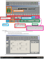
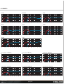
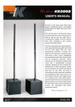
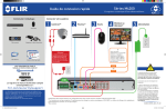
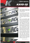
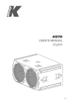
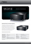
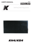
KL18ma
USER'S MANUAL
K-array is the new voice that sings
aloud, "outside the choir", and whose
performance is better than any other
products.
Born on-the-road, in the PA world, where
you get no discount, you have to give your
best as fast as you can, often with a
"compressed" budget, K-Array systems
have been designed to give precise
answers to precise needs.
Driven by new generation digital engines,
with power/dimension/weight ratios that
are ten times better than any other
professional products, K-arrays can
deliver the full spectrum of musical styles
with clarity, power, punch, intelligibility
and evenness across both volume levels
and the frequency spectrum. These
systems can be remotely controlled and
come with a sophisticated on-board
software, allowing the user to shape their
performance to taste and needs. Inside
K-array systems you will find something
that only we can offer: the best in
technology, proudly conceived, designed
and produced in Italy. If they were cars,
they would be Ferrari. Don't agree to pay
for a simple brand, claim performance,
and don't believe those who maintain that
these products are only for few people,
the only truth is that K-array systems are
unique, but affordable and within
everybody's reach!
HP Sound Equipment s.r.l.
USER'S MANUAL
REV. A
ENGLISH
SYMBOLS
!
This symbol, wherever it appears, alerts you to Wa r n i n g ! D a n g e r o u s
important operating and maintenance istructions in voltages: risck of electric
schock.
the accompanying literature. Read the manual!
This device complies with
Restriction of Hazardous
Substances Directive.
Separate collection of electrical and electronic
devices.
For information about the disposal of Waste Electrical
and Electronic Equipment (WEEE), please refer to
the website at
www.scanning.datalogic.com
This symbol alerts the
user to the presence of
recommendations about
product's use and
maintenance.
The item meets all the
essential "Health and
Safety" requirements of
the revelant European
Directives.
1. SAFETY INSTRUCTIONS
!
CAUTION
!
• To reduce the risk of electric shock, disconnect the amplifier from the AC mains before installing audio cable.
Reconnect the power cord only after making all signal connections.
• Connect the amplifier to a two-pole, three wire grounding mains receptacle. The receptacle must be connected to
a fuse or circuit breaker. Connection to any other type of receptacle poses a shock hazard and may violate local
electrical codes.
• Do not install the amplifier in wet or humid locations without using weather protection.
• Do not allow water or any foreign object to get inside the amplifier. Do not put objects containing liquid on, or near,
the unit.
• To reduce the risk of overheating the amplifier, avoid exposing it to direct sunlight. Do not install the unit near heat
emitting appliances, such as a room heater or stove.
• No naked flame sources such like lighted candles should be placed on the device.
• The amplifier should be placed so that its location does not interfere with its proper ventilation. For example, the
appliance should not be situated on a bed, carpet, or similar surface that may create an obstacle for the ventilation
openings.
USER'S MANUAL
REV. A
pag. 02
ENGLISH
2. INTRODUCTION
The KL18ma features a 1600 watt 18" drive unit with neodymium magnet structure and suspension
engineered for maximum linear excursion. Its ultra-light reflex cabinet is fitted with two pocket
handles and one 35mm pole mounting point for easy installation with every satellite speaker on it.
Combinig the KL18ma with the middle-high speakers KR200, we obtain a high performance ultraslim powered two way system, called KR200S, designed for small to medium wavefront systems, in
both mobile and installed applications.
The KR200S includes two KR200 satellites and 2 KL18ma powered subwoofers.
The KR200S features a line array of 32x2" high efficiency neodymium magnet drivers enclosed in an
ultra-strong chassis, to ensure high resistance and durability in the hardest working conditions.
The KR200S thanks to true line array technologies and powerful DSP system, achieve outstanding
power and coherence throughout the intended coverage allowing a wide dynamic range and a
faithful reproduction of sound.
All the components are designed by K-array R&D department and custom made under K-array
control quality system.
3. VOLTAGE REQUIREMENTS
KL18ma operates safely and without audio discontinuity if the AC voltage stays within either of two operating
windows:
95-125 (voltage selector on 115 V) or 195-250 V (voltage selector on 230 V), at 50 or 60 Hz.
115-230
The device is default set to be connected to 230 V AC Power. To use the device on a 115 V AC Power you need,
before connecting it, to move the voltage selector's cover, just loosening the two screws, and to choose the correct
use voltage by the red switch. Be sure that both voltage set on the selector and AC Power have the same value .
Always close the voltage selector's cover before connecting the device to AC Power. Change the label that points
out the correct voltage in use.
CAUTION
!
USER'S MANUAL
REV. A
Connecting a 115V system
on a 230V
AC Power causes heavy
damages to the device and serious risk for users .
pag. 03
ENGLISH
4. AMPLIFIER PANEL
Balanced XLR
In \ Out parallel
LINK
(parallel)
INPUT
(balanced)
PUSH
LIMIT
ON
35
18 12
9
0
0
Input pad level
6
0
0.5
ANALOG
GROUND
LIFT
5
3 4
INPUT
PAD
dB
PRESET
ADDRESS
RS485 connection
for remote control
(don't connect to
LAN port!)
keep pressed
for preset lock
Ground lift switch
REMOTE
RS485
DSP
ID12
PRESET
WARNINGS:
To ensure correct operation,
allow at least
20 cm clearance from
back surface and correct
ventilation. To reduce risk of
electric shockdo not remove
cover. No operatoror serviceable
parts inside. Refer servicing to
qualified personnel. To reduce the
risk of fire or electric shock do
not expose this appliance to
rain or moisture.
is a product of
Preset change button
Keep it pressed 10sec.
to store preset as default
ID number
remote control
for
Preset loaded
HP Sound Equipment srl
viale Roma 7/i, 50037 S.Piero a Sieve
Firenze ITALY Tel + 39 055 8487222
DO NOT EXPOSE
TO RAIN OR MOISTURE!
Speakon power
output.
To use with KR200
satellite or with
KL18 passive
subwoofer
CAUTION
RISK OF ELECTRICAL SHOCK
DO NOT OPEN!
I
0
POWER
OUTPUT
ATTENTION
RISQUE DE CHOC ELECTRIQUE
NE PAS ENLEVER!
POWER
ON
PARALLEL
OUT
INPUT
ATTENTION!:
READ MANUAL FOR
CORRECT
PRESET SELECTION
LINK
1+
12+
2-
POSITIVE OUT
NEGATIVE OUT
N.C.
N.C.
POWER SUPPLY
MADE IN ITALY
PowerCon Input
USER'S MANUAL
REV. A
pag. 04
PowerCon parallel Output
(max 14 A)
ENGLISH
5. PHYSICAL
58.5 cm
46.5 cm
KL18ma
46.5 cm
WEIGHT
20 Kg
7 cm
KR200
WEIGHT
9 Kg
200 cm
Open and lock the KR200 satellite
before installing on the KL18ma.
Warning
Pay attention when closing the
KR200 satellite, do it slowly and
watch your hands!
USER'S MANUAL
REV. A
100 cm
pag. 05
ENGLISH
6. DSP CONTROL & REMOTE CONTROL
A powerful DSP manages all the functions of the speakers. Each system can store on board 16 preset that can be recalled pushing
the PRESET button. Once the preset will appear on the lower line of the display it will become automatically available after few
seconds. If you desire to set a preset as “default” you just need, once selected it, to keep pressed for five seconds the PRESET
button. After that, this preset will automatically be recall each time you will switch on your module. It is also possible to remote each
module by an RS485 serial port. In order to remote your system, you need to set each module on a different address, so that, in your
chain, no one module will have the same address. Two rotary encoders allow you to set the desired address number that will appear
on the top line of the display. Using the remote control software it is possible to mute each system, select a desired preset loaded onboard or download a new preset pack.
For remote control operation please refer to REMOTE CONTROL AND SOFTWARE MANUAL in the next pages.
6.1 Cloner function & preset systems
It is possible to clone the entire presets bank from Speaker to Speaker without any PC connected. We will call
SpeakerA the one with the presets bank that you want clone, and SpeakerB the one that will be upgraded.
Set the SpeakerA on ID 99, will appear CLONER on the display
Keep SpeakerB on any ID number between 10 and 90.
Turn off both the speakers and connect by a RJ45 8 poles cable
Turn on the SpeakerB and after the SpeakerA
SpeakerA will start to clone, on the display will appear a cont down (00/15, 01/15, etc)
Wait till 20 seconds after 15/15
Change the ID of the SpeakerA to any other ID and turn off both Speakers
Turning on the SpeakerA check that it is on mode 16x16 and NOT 4x4.
If SpeakerA is in mode 4x4, just turn off the speaker and keep press the Preset button during the turning on
The preset are cloned to the SpeakerB.
USER'S MANUAL
REV. A
pag. 06
ENGLISH
7. REMOTE CONTROL SOFTWARE
1 . To connect the K-array modules to a PC, it is needed a RS485-USB adapter, we recommend the K-USB adapter (pic.1).
K-USB
USB to RS485 adapter
Connect the K-usb to a PC and install the drivers required included in the CD-ROM.
SYSTEM REQUIREMENTS
Operating systems:
Win98/98SE/Me/2000/XP/Vista
1
Minimum requirements:
CPU
300 MHz
RAM
128 Mb
Recommended requirements:
RAM
512 Mb
2 . Install the K array control software from installer in the CD-ROM
2.1 Start the Karray_manager_V2 from Windows - Start - Software - Karray_manager_V2
2.2 Click on NO when ask for demo mode start
2.3 Click on System - Settings to configure which COM port use, the COM port of K-USB, usually is the higher number.
If you don't find, you can check it on windows-control panel-system-hardware-COM Port
USER'S MANUAL
REV.A
pag. 07
ENGLISH
3 . ID setting
FROM PC
On this bars you can see all the
Pressing this button you can have a
modules connected in your net.
refresh of the modules connected.
ID X 10
DX1
I
PRESET SELECTOR
ID 39
cbClear
ADDRESS
PRESET IN USE
4 . Single module control
This frame describes the state of all the loudspeakers on the net.
The colour of the little rectangles into this frame represents the
status of the loudspeakers. Each loudspeaker has three rectangles.
Here there is the meaning of the rectangle's colour.
Click once on the ID module
Two rectangles on top:
that you want control.
Both rectangles grey: the loudspeaker is not present on the net.
Temperature rectangle red: one module inside that loudspeaker is
over-temperature.
Temperature rectangle green: all modules inside that loudspeaker
have a good temperature.
Protection/Fail rectangle red: at least one module inside that
loudspeaker is in protection.
Temperature rectangle green: all modules inside that loudspeaker
are working properly.
Temperature rectangle black: if this rectangle is black it means that
the loudspeaker is not responding.
The main causes of this malfunction are
loss of power supply and loss of serial
connection between the hub and the
loudspeaker. Check the hardware. If
this rectangle is black will be black also
the Protection/Fail.
Protection/Fail rectangle black: see
Module status panel
Preset slots on the
above.
The remaining rectangle: Is related to
the mute function; if red, the related
loudspeaker is in "mute" status.
USER'S MANUAL
REV.A
pag. 08
ENGLISH
Module status panel
Preset names, you can change it
Store the active preset to default
from the area on the right
when restart the module
Mute Module
Select the preset number, write
the
name,
maximum
Module details
5
characters, press the Send
With this button, you can load presets from PC to the
button
module, you have to press, choose the slot that you
want use and select the .EQS file that you want to
load.
5. Mute groups
On the Mute Groups window, you can manage the modules Mute as groups, up to 4 different.
5.1
Choose the modules from the list on the right
Press the right arrow of the group that you prefer, to add the modules
5.2 It is possible to assign names to the groups, just writing in the fields.
USER'S MANUAL
REV.A
pag. 09
ENGLISH
6. Preset groups
On the Preset Groups window, you can manage the modules Presets as groups, up to 4 different.
6.1
Choose the modules from the list on the right
Press the right arrow of the group that you prefer, to add the modules
Select the number of the preset you want to choose, after press Change button
6.2 It is possible to assign names to the groups, just writing in the fields.
7. Text editor
It is available a text editor on the software, it can manages .RTF files.
USER'S MANUAL
REV.A
pag. 10
ENGLISH
8. Master Mute control
It is possible to Mute all the modules connected just pressing Master Mute button.
To protect from accidental pressing of this button, you will need to Unlock by pressing the Unlock button below it.
9. Exit option
When you choose to exit from the software, will appear an alert window that alert you about Unmuting all the modules
connected, this is important because the Mute function is controlled only by software.
10. Save and Load
It is possible to save the speakers configuration for Mute and Preset Groups, just Save a .CONF file.
It is possible to use XLR adapters for connections, here below, the connection schematic.
1
2
3
1 2 3 4 5 6 7 8
USER'S MANUAL
REV.A
brown
white orange
green
white green
white blue
blue
pag. 11
1
1
2
2
3
3
ENGLISH
8. TECHNICAL DATA
Acoustics
Power handling
Max power
Impedance
Operating frequency range
Frequency range
SPL 1W/1mt
Maximum SPL
1
800(sub) + 500(sat) w
2
1200(sub) + 1200(sat) w
8 W (sub) + 8 W (sat)
3
30Hz - 19 KHz +/- 3dB (preset relating)
35Hz - 19 KHz +/- 3dB (preset relating) 4
5
97 dB(sub) 101 dB(sat)
127dB continuos - 133 dB peak 6
Cross over
Type
Frequency
DSP controlled preset relating
150 Hz minimum (preset relating) 7
Transducers
Low frequency
High frequency (KR200)
1 x 18" Neodymium speakers with 3" voice coil
32 x 2" Neodymium speakers with 0,75" voice coil
Audio Input
Connectors
Wiring
male + female parallel 3 poles balanced XLR
Pin1 = ground / Pin2 = hot / Pin3 = cold
Audio powered Output
Connector
Wiring
Female Speakon
Pin1+ = CH1+ / Pin1- = CH1- / Pin2+ = N.C. / Pin2- = N.C.
Remote control Input
Connectors
1 x female 8 poles RJ45
Power Input
Connectors
2 x PowerCon IN/OUT (max out 14 A)
Amplifiers
Type
Subwoofer power
Satellite power output
Protections
1 modules class D - DSP controlled
8
1000 Watt
1000 Watt 8
Dynamic limiter, over current, over temp, short circuits
AC power
Operating range
Max continuos and burst current
Standard 210 - 240 Vac 50Hz (standard)
Optional 100 - 120 Vac 60Hz (optional)
Standard 6A(>10 sec) - 12A (<1 sec)
Optional 10A(>10 sec) - 20A (<1sec)
Physical
Measures
Weight
46.5 x 46.5 x 58.5 cm (KL18ma) 5.5 x 7 x 200 cm (KR200)
20 Kg (KL18ma) 9 Kg (KR200)
Notes for data
1. Power handling is measured following AES standard conditions: transducers driven continuously for two hours with a band-limited noise signal having 6 dB of crest factor.
2. Max power is the maximum RMS applicable power for a musical signal, the referement signal is the one proposed by EIAJ standard.
3. Recommended maximum operating frequency range. Response depends on loading conditions and room acoustics.
4. Free field measured with 1/3 octave frequency resolution at 2 mt.
5. Measured@4 mt then scaled@1 mt.
6. Measured with audio source @1 mt.
7. This is the frequency in which the transducers produce the same sound pressure level (measured@2 mt).
8. Amplifier wattage rating is based on the maximum unclipped burst sine wave RMS voltage that the amplifier will produce into the nominal load impedance .
HP Sound Equipment s.r.l. - www.k-array.com
Viale Roma 7/i 50037 San Piero a Sieve (Firenze) Italy - tel +39 055 8487222 fax +39 055 8487238 e-mail: [email protected]
USER'S MANUAL
REV. A
pag. 12
ENGLISH
9. PRESETS
Clear
Smooth
Tony
Back
Dark
HP60
Disco
Live
Cl-3 (Clear - 3dB Sub)
Li-3 (Live -3dB Sub)
Li-6 (Live -6dB Sub)
To-3 (Tony -3dB Sub)
To-6 (Tony -6dB Sub)
Cl-6 (Clear - 6dB Sub)
USER'S MANUAL
REV. A
pag.13
ENGLISH
NOTES
USER'S MANUAL
REV. A
pag. 14
ENGLISH
NOTES
The contents of this manual are fornished for informational purpose
only. Hp Sound Equipment s.r.l. assumes no responsability for any
errors or inaccuracies that may appear in this manual.
Hp Sound Equipment s.r.l. reserves the right to make modifications
without prior notice.
arr
a
y
K
www.k-array.com
by
HP Sound Equipment s.r.l.
Viale Roma 7/i
50037 San Piero a Sieve (Firenze)
Italy
tel +39 055 8487222 fax +39 055 8487238
e-mail: [email protected]