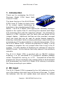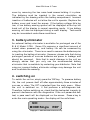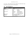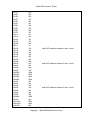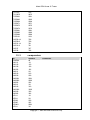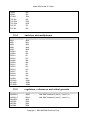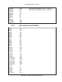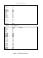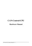
1
Model 570A Linear IC Tester MODEL 570A HANDHELD LINEAR IC TESTER OPERATOR’S MANUAL Copyright 1993-2007 B&K Precision Corp. Model 570A Linear IC Tester CONTENTS 1. introduction .............................................................................. 2 2. DC input ................................................................................... 2 3. battery eliminator ..................................................................... 3 4. switching on.............................................................................. 3 5. operating modes....................................................................... 4 6. entering test numbers............................................................... 4 7. testing the IC ............................................................................ 5 8. test results................................................................................. 6 9. testing further ICs...................................................................... 8 10. continuous testing ................................................................. 8 11. search mode.......................................................................... 9 12. self test mode ...................................................................... 10 13. CompactLink mode ............................................................. 10 14. specifications....................................................................... 11 15. IC support list....................................................................... 12 introduction................................................................................ 12 15.2. operational amplifiers................................................... 12 15.3. comparators.................................................................. 15 15.4. switches and multiplexers............................................. 16 15.5. regulators, references and virtual grounds..................... 16 15.6. opto couplers and isolators........................................... 17 15.7. miscellaneous............................................................... 18 16. Service Information ............................................................. 19 17. Limited One-Year Warranty................................................. 20 Copyright 1993-2007 B&K Precision Corp. Model 570A Linear IC Tester 1. introduction Thank you for purchasing the B & K Precision Model 570A Hand Held Linear IC Tester. The basic function of the B & K Model 570A Linear IC Tester is to test a linear IC for correct logical functioning as described in the manufacturer’s IC data sheets. The B & K Model 570A applies the necessary analogue signals to the inputs of the IC, monitoring the outputs at each stage and comparing them with the expected voltages. Any discrepancy results in a FAIL indication and the faulty pins are shown on the integral display. Additional facilities are also provided, amongst them test loops that can be used for goods inwards inspection, detecting intermittent faults or simply providing a rapid method of exercising any IC for demonstration or educational purposes. Since the B & K Model 570A contains an extensive IC library, it is not necessary to program the unit yourself other than to key in the IC number. It is also capable of identifying an unknown IC using the SEARCH mode - this is a feature that many users will find extremely valuable. The B & K Model 570A is provided with an RS-232 interface enabling it to be connected to a companion software package called CompactLink running on a PC. CompactLink allows test programs for ICs not included in the internal library to be developed and downloaded into the B & K Model 570A memory to enhance the library according to your wishes. 2. DC input The B & K Model 570A is powered by four AA batteries or by the use of the battery eliminator input at the rear of the case. To insert the batteries, turn the unit upside down and remove the battery Copyright 1993-2007 B&K Precision Corp. Model 570A Linear IC Tester cover by removing the two cross head screws holding it in place. The batteries must be inserted in the correct orientation, as indicated by the drawing within the battery compartment. Incorrect insertion of batteries will not allow the unit to operate. Replace the battery cover and insert the screws. If the battery voltage falls too low, a low battery warning symbol will be displayed at the top left hand cell of the display in normal operating mode. A low battery warning will also be displayed during a result display. Test results may be inconsistent under these conditions. 3. battery eliminator An external battery eliminator is available for prolonged use of the B & K Model 570A. Some ICs consume a significant amount of current when powered up, and battery life can be conserved by using the eliminator. There is no need to remove the batteries prior to inserting the battery eliminator. However, please note that during prolonged periods of non-use batteries are prone to leakage and should be removed. Note that to avoid damage to the unit we strongly advise that you only use the recommended battery eliminator that is available by contacting your distributor. Note that using an incorrect battery eliminator voltage may damage the unit and invalidate the warranty. 4. switching on To switch the unit on, simply press the 'ON' key. To preserve battery life, the unit powers itself off after approximately three minutes of non-use or when “Sw Off” is selected from the main menu. When the unit is switched on, it first performs a self-diagnosis test. Therefore, before switching on, check that the test socket is empty to prevent interference with the diagnostics. If the unit passes the selftest, a pass result will be displayed on the screen. Press a key to enter the main operating mode - the display will be as follows: NO: MODE:Single :RDY Copyright 1993-2007 B&K Precision Corp. Model 570A Linear IC Tester When this initial display is obtained the B & K Model 570A is ready for use. If, however, the message SELF-TEST FAIL: is displayed along with a fault message, this indicates that a self-test diagnostic fault has been detected. Any detected faults will be displayed one at a time. Pressing the TEST/EXEC key will then revert to the opening menu as above, but of course operation of the unit will then be suspect. Before contacting your distributor, check that the test socket is completely empty. 5. operating modes The B & K Model 570A has a number of test modes that are selected using the MODE/CLEAR key from the initial screen. The test modes are as follows: Single Loop P Loop F Loop Search Diags CmLink Sw Off - execute a single test on the IC in the socket. - execute test repeatedly, regardless of the result. - execute test repeatedly, provided the result was PASS. - execute test repeatedly, provided the result was FAIL. - identify the number of the IC in the socket. - execute the diagnostic self-test. - enter remote mode for CompactLink software. - turn off the unit 6. entering test numbers Press the MODE/CLEAR key until the desired test mode is displayed. Enter the number of the IC you wish to test. Pressing the MODE/CLEAR key will clear the last digit from the display if a mistake is made. Note: The NUMERIC information only is entered, leav ing out the manufacturers prefixes and suffixes and IC family information. As an example, all the follow ing linear ICs should be entered as 7, 4, 1 on the keypad: e.g. uA741CP, uA741M, uA741C etc Copyright 1993-2007 B&K Precision Corp. Model 570A Linear IC Tester Some ICs are available in different pin outs or package types, and also there may be several different types of IC with the same numerical part number. In these cases the B & K Model 570A will automatically determine which test to perform. If however the IC is faulty the unit may not be able to determine the correct IC type - if this happens a warning message will be displayed. A complete list of all ICs supported by the B & K Model 570A is contained in the IC SUPPORT LIST at the end of this manual together with notes on any special requirements for certain ICs. Note that if you have stored a user library using CompactLink, an IC in the user library with the same number as one in the internal library will take precedence. This allows a new test to be written for an existing IC. If you wish both tests to be available, use a different number for your user test. 7. testing the IC The test socket is a 24 pin shell with 16 active pins. Insert the IC to be tested in the front of the 24 pin Zero Insertion Force socket with pin 1 towards the display as shown below: For 3 pin TO220 or TO92 packages, insert the IC in pins 6, 7 and 8 (lower left) of the socket with the metal tab or flat side facing to the right. Ensure that the operating lever on the socket is in the open (i.e. up) position before inserting the IC. Close the socket by lowering the lever, making sure that the IC is firmly seated in the socket and Copyright 1993-2007 B&K Precision Corp. Model 570A Linear IC Tester making good contact. Press the TEST/EXEC key to activate the test sequence for the IC. If an invalid IC type number was entered, or if the IC you have requested is not supported the message "Unknown" will be displayed. Simply entering another IC type number will automatically clear this error message. If a valid type number was entered, the IC test will begin and the message "BUSY" will be displayed while the test proceeds. Many of the tests, however, execute so quickly that this message is not noticeable. 8. test results A pre-determined sequence of signals is applied to the inputs of the IC under test and the output voltages are measured prior to comparing with the correct values. The exact nature of the test depends on the function of the IC, but as an example the operational amplifier tests include both open and closed loop testing over a range of input voltages and gain settings. If all the outputs respond correctly, the result PASS will be displayed at the top right of the display. A scrolling message will contain the IC function and power pin information. If a short circuit between the power pins of the IC is detected, a warning ‘SHT!' will appear on the top right of the display and, since no valid test is then possible, the result will FAIL. If the IC under test takes an excessive amount of current when power is applied, a warning 'ICC!' will appear. Press the TEST/EXEC key to continue with the test, or MODE/CLEAR to abandon. Depending on the condition of the batteries there may also be a ‘BAT!’ warning which indicates that the batteries are incapable of supplying the current required by the IC under test. You can continue with the test by pressing the TEST/EXEC key, but the unit may malfunction because of a drop in battery voltage. To avoid this, change the batteries or use a battery eliminator. Note that a faulty IC may demand more operating current and therefore will quickly drain the batteries. Some ICs require external components to be fitted prior to the test in these cases the message EXT or CAP will be displayed at the top right of the display. Please refer to the IC lists at the end of this Copyright 1993-2007 B&K Precision Corp. Model 570A Linear IC Tester manual for details of the component(s) required. After fitting the component the test can be carried out by a further press of the TEST key. If you wish you can abandon the test by pressing the CLEAR key. In the case of a FAIL result, the error conditions at all the nonfunctional pins of the IC will be scrolled on the display, and the IC function will be shown. The various failure conditions that can be displayed are as follows: V<< V>> D<< D>> LOAD - the voltage on the pin was lower than expected. - the voltage on the pin was higher than expected. - the diode drop voltage was lower than expected. - the diode drop voltage was higher than expected. - the input cannot be driven. In some cases, the scrolling test results may include one or more WARNING indications. These warnings indicate conditions that may result in an incorrect test result, and are as follows: D/F BAT ICC - result may be invalid because last self-test failed. - battery voltage too low during test - large current taken by IC under test Some ICs are available in various packages, and also there are some ICs in the library which have the same numerical part number even though the IC functions are different. In these cases the B & K Model 570A will automatically determine the IC type prior to the test, provided that the IC is functional. If the IC is faulty, the following warning will appear after the test: WARNING: All Part Types FAIL This indicates that the IC is faulty, but the pin information cannot be displayed since the exact part type cannot be identified. Before discarding a failed IC check that the correct IC type number was entered and also check that the IC pins are clean and making good contact with the test socket. Note that there is no way of Copyright 1993-2007 B&K Precision Corp. Model 570A Linear IC Tester stopping a test once it has commenced, but see the description of loop functions later in this manual. 9. testing further ICs After a test is completed, the test result will be displayed. To test another IC of the same type, simply insert the next IC and press the TEST/EXEC key again. To test a different IC, enter the new IC type number in the usual way, noticing that pressing the first digit of the new number automatically clears the previous number from the display. Remember that the MODE/CLEAR key can be used if an error is made during the entry of the IC type number. 10. continuous testing It is possible to test the same IC repeatedly to detect intermittent or temperature-related faults, or to rapidly test a batch of identical ICs. There are three types of test loop modes: Loop - execute a test repeatedly, regardless of the result. P Loop - execute a test repeatedly, provided the result is PASS. F Loop - execute a test repeatedly, provided the result was FAIL. The B & K Model 570A is configured into one of the loop modes using the MODE/CLEAR key as described earlier. Insert the IC and press TEST/EXEC in the usual way to start the continuous test process. The result of each test is displayed as PASS or FAIL on the top right of the display. In LOOP mode, this allows a large batch of identical ICs to be tested, without any action on the part of the operator other than inserting the IC. When the IC is inserted, sufficient time must be allowed for the test to take place before the result status is updated, so if in doubt the IC should be tested in single mode so that the approximate test time can be determined. It will be found that high throughput can be obtained using this mode. To stop any of the test loops, press MODE/CLEAR, but note that the test in progress is completed before the command is obeyed. The Copyright 1993-2007 B&K Precision Corp. Model 570A Linear IC Tester effect of this is usually unnoticeable, but where the test takes a reasonable time to execute there will be a delay before the instrument responds to the MODE/CLEAR key. Note: Testing high current ICs in loop mode w ill drain the batteries quickly, and it is recommended that a battery eliminator is used if you w ish to perform loop tests. 11. search mode This feature allows the type number of an unknown IC to be determined, provided the IC is actually contained in the B & K Model 570A library, and it is a correctly functioning IC. This facility is useful when the IC type number is illegible or has been removed. Use the MODE/CLEAR key to choose SEARCH mode, insert the unknown IC into the socket and press the TEST/EXEC key. You will be prompted to choose the number of pins of the IC you wish to identify - use the MODE/CLEAR key to select from 3 to 16 pins or 'QUIT' to abandon this mode. Press the TEST/EXEC key again to start the SEARCH or to quit as required. During the identification process the display will indicate the number of ICs identified (IDENT:) and will show graphically how far through the library the SEARCH has progressed. At the end of the SEARCH, a list of all the similar ICs will be scrolled onto the display. The list may be scrolled again by pressing the TEST/EXEC key. If the IC cannot be identified the message "Not in Library" will be displayed. This means either that the IC is not in the library or it is non-functional. Note that if the B & K Model 570A detects excessive supply current (ICC! or BAT! warnings), the IC will not be identified during the SEARCH, but can still be tested in SINGLE mode. If you have a user library present the search will extend to user ICs in that library also. However, CompactLink contains a facility for excluding ICs from the search if required. Copyright 1993-2007 B&K Precision Corp. Model 570A Linear IC Tester 12. self test mode This feature allows you to check the integrity of the unit, including the pin drivers and receivers, power supplies and other internal hardware. The test executes automatically at switch on, but you can if you wish perform a self-test at any time by selecting Self-Test (DIAGS) mode using the MODE/CLEAR key and pressing TEST/EXEC. If a fault is discovered a brief description will be displayed which will help our engineers to locate and rectify the fault. This message should be noted and quoted in any correspondence relating to a unit fault. Contact your distributor in the event of a self-test fail, but first of all ensure that the socket was empty when the diagnostics were run. 13. CompactLink mode The B & K Model 570A is provided with an RS-232 interface to connect to a PC with a serial COM port or using a USB to RS-232 converter. A companion software package CompactLink is available which provides library management, test development and debugging and user library update facilities. You can also use CompactLink to update the software of your B & K Model 570A without replacing the internal memory or opening the case. To enter CompactLink mode, user the MODE/CLEAR key to enter CMLINK mode, then press TEST/EXEC. Press TEST/EXEC again to confirm that you wish to enter CompactLink mode, and the display will show “Not Connected”. Run the CompactLink software on your PC, connect the serial cable and follow the CompactLink manual instructions to connect to the B & K Model 570A. For comprehensive instructions on using CompactLink please refer to the manual and built-in help supplied with the software. Note that in CompactLink mode, including waiting for a connection, the normal power down timeout is disabled and the unit will remain Copyright 1993-2007 B&K Precision Corp. Model 570A Linear IC Tester on for ever. We recommend using a battery eliminator when using CompactLink mode to develop test programs. 14. specifications SPECIFICATIONS Batteries: DC input: Power consumption: Test parameters: RS-232 settings Dimensions: Library ICs: 4 X AA size 6V, 850mA max, center positive, regulated. Power off 10A max Standby 30mA max Testing IC dependent Supply voltage 2V to 10V IC dependant Op amp gains open loop, 1,2,11,46 Stimulus 0 - 10V, 8 bits, 330R source Sense 0 to 10.5V, 12 bit, >1M load 38400 baud, 8 data bits, 1 stop bit, no parity 200mm X 100mm X 55mm approx. Op amps, comparators, optos, regulators, references, switches, miscellaneous Copyright 1993-2007 B&K Precision Corp. Model 570A Linear IC Tester Softw are Version No. 15. IC support list BK570A 2.03 15.1. introduction This section is a complete list of the ICs supported by the B & K Model 570A. If there are any special requirements necessary for a particular IC, this will be indicated in the comments column in the table. Always consult this list before testing an IC you have not tested before, particularly when there is a comment present. 15.2. IC AD546 AD548 AD645 AD648 AD711 AD712 AD713 AMP03 CA1458 CA3080 CA3130 CA3140 CA3160 CA3240 CA3260 CA5130 CA5160 CA5260 HA3-2840-5 ICL7611 ICL7612 ICL7621 ICL7641 ICL7642 L272 LF147 LF155 LF156 operational amplifiers Number 546 548 645 648 711 712 713 03 1458 3080 3130 3140 3160 3240 3260 5130 5160 5260 328405 7611 7612 7621 7641 7642 1272 147 155 156 Comments Copyright 1993-2007 B&K Precision Corp. Model 570A Linear IC Tester LF157 LF255 LF256 LF257 LF347 LF351 LF353 LF355 LF356 LF357 LF411 LF412 LM101 LM107 LM108 LM11 LM118 LM124 LM148 LM158 LM201 LM207 LM208 LM218 LM224 LM248 LM258 LM2900 LM2902 LM2904 LM2924 LM301 LM307 LM308 LM318 LM324 LM348 LM358 LM3900 LM392 LMC6032 LMC6042 LMC660 157 255 256 257 347 351 353 355 356 357 411 412 101 107 108 11 118 124 148 158 201 207 208 218 224 248 258 2900 2902 2904 2924 301 307 308 318 324 348 358 3900 392 6032 6042 660 Add 47nF capacitor between IC pins 1 and 6 Add 47nF capacitor between IC pins 1 and 6 Add 47nF capacitor between IC pins 1 and 6 Copyright 1993-2007 B&K Precision Corp. Model 570A Linear IC Tester LT1013 LT1014 MAX407 MAX427 MC3303 MC33171 MC33172 MC33174 MC3403 NE531 NE5532 NE5534 OP-07 OP200 OP-27 OP-282 OP290 OP-37 OP-42 OP482 OP490 OP-77 OP-90 OP-97 OPA121 OPA606 OPA620 RC4458 TL061 TL062 TL064 TL071 TL072 TL074 TL081 TL082 TL084 TLC1079 TLC2272 TLC271 TLC272 TLC274 TLC277 1013 1014 407 427 3303 33171 33172 33174 3403 531 5532 5534 07 200 27 282 290 37 42 482 490 77 90 97 121 606 620 4458 061 062 064 071 072 074 081 082 084 1079 2272 271 272 274 277 Copyright 1993-2007 B&K Precision Corp. Model 570A Linear IC Tester TLC279 TLC2872 TLE2061 TLE2062 TLE2064 TLE2071 TLE2072 TLE2074 TLE2081 TLE2082 TLE2084 TLE2161 UA709-14 UA709-8 UA741-14 UA741-8 UA747 UA748 15.3. IC CMP04 LM111 LM119 LM139 LM193 LM211 LM219 LM239 LM2901 LM2903 LM293 LM311 LM319 LM3302 LM339 LM393 LP111 LP211 LP239 LP265 LP2901 LP311 279 2872 2061 2062 2064 2071 2072 2074 2081 2082 2084 2161 709 709 741 741 747 748 comparators Number 04 111 119 139 193 211 219 239 2901 2903 293 311 319 3302 339 393 111 211 239 265 2901 311 Comments Copyright 1993-2007 B&K Precision Corp. Model 570A Linear IC Tester LP339 LP365 LT1016 TLC339 TLC3702 TLC3704 TLC372 TLC393 15.4. IC 4016 4051 4052 4066 4529 DG201 DG202 DG211 DG212 DG308 DG309 DG411 DG412 DG413 DG417 DG418 DG419 DG508 LF13201 LF13202 LF13508 15.5. IC LM2930-5 LM2931-5 LM340T5 LM7805 LM7806 LM7808 339 365 1016 339 3702 3704 372 393 switches and multiplexers Number 4016 4051 4052 4066 4529 201 202 211 212 308 309 411 412 413 417 418 419 508 13201 13202 13508 Comments regulators, references and virtual grounds Number 29305 29315 3405 7805 7806 7808 Comment Add 100uF between IC pins 2 (-) and 3 (+) Add 100uF between IC pins 2 (-) and 3 (+) Copyright 1993-2007 B&K Precision Corp. Model 570A Linear IC Tester LM7905 MAX667 MAX872 MAX874 REF02 REF03 REF05 REF43 TLE2425 TLE2426 15.6. IC 4N25 4N26 4N27 4N28 4N29 4N30 4N31 4N32 4N33 4N35 4N36 4N37 6N135 6N136 H11A1 H11A2 H11A3 H11A4 H11A5 HCPL2503 HCPL2530 HCPL2531 HCPL4502 HCPL4503 ILCT6 ILD74 ISD74 LD428 MCT2 MCT210 7905 667 872 874 02 03 05 43 2425 2426 May need 10uF between IC pins 2 (-) and 3 (+) May need 10uF between IC pins 4 (-) and 2 (+) opto couplers and isolators Number 425 426 427 428 429 430 431 432 433 435 436 437 6135 6136 111 112 113 114 115 2502 2530 2531 4502 4503 6 74 74 428 2 210 Comments Copyright 1993-2007 B&K Precision Corp. Model 570A Linear IC Tester MCT2200 MCT2201 MCT2202 MCT271 MOC8030 MOC8050 TIL197 TIL198 TIL199 TLP250 TLP521 TLP521-2 TLP521-4 TLP559 TLP621 TLP621-2 TLP621-4 15.7. IC AD7524 DAC08 NE555 NE556 ULN2001 ULN2002 ULN2003 ULN2004 ULN2064 ULN2065 ULN2066 ULN2067 ULN2068 ULN2069 ULN2070 ULN2071 ULN2074 ULN2075 ULN2076 ULN2077 2200 2201 2202 271 8030 8050 197 198 199 250 521 5212 5214 559 621 6212 6214 miscellaneous Number 7524 08 555 556 2001 2002 2003 2004 2064 2065 2066 2067 2068 2069 2070 2071 2074 2075 2076 2077 Comment Copyright 1993-2007 B&K Precision Corp. Model 570A Linear IC Tester 16. Service Information Contact B&K Precision to receive a repair Return Authorization tracking number. This number must be clearly written on the exterior of the shipping carton and will assist us with the processing of your return. Return all merchandise to B&K Precision Corp. with pre-paid shipping. The flat-rate repair charge includes return shipping to locations in North America. For overnight shipments and non-North America shipping fees contact B&K Precision Corp. Warranty Serv ice: Please return the product in the original packaging with proof of purchase to the below address. Clearly state in writing the performance problem and return any leads, connectors and accessories that you are using with the device. Non-Warranty Serv ice: Return the product in the original packaging to the below address. Clearly state in writing the performance problem and return any leads, connectors and accessories that you are using with the device. Customers not on open account must include payment in the form of a money order or credit card. For the most current repair charges contact the factory before shipping the product. B&K Precision Corp. 22820 Savi Ranch Parkway Yorba Linda CA 92887-4604 Phone: 714- 921-9095 Facsimile: 714-921-6422 Include with the instrument your complete return shipping address, contact name, phone number and description of problem. Protected by the manufacturer’s copyright laws. All rights reserved. Copyright 1993-2007 B&K Precision Corp. Model 570A Linear IC Tester 17. Limited One-Year Warranty B&K Precision Corp. warrants to the original purchaser that its product and the component parts thereof, will be free from defects in workmanship and materials for a period of one year from the date of purchase. B&K Precision Corp. will, without charge, repair or replace, at its’ option, defective product or component parts. Returned product must be accompanied by proof of the purchase date in the form a sales receipt. To obtain warranty coverage in the U.S.A., this product must be registered by completing and mailing the enclosed warranty card to: B&K Precision Corp., 22820 Savi Ranch Parkway, Yorba Linda, CA 92887 - 4604 within fifteen (15) days from proof of purchase. Exclusions: This warranty does not apply in the event of misuse or abuse of the product or as a result of unauthorized alterations or repairs. It is void if the serial number is altered, defaced or removed. B&K Precision Corp. shall not be liable for any consequential damages, including without limitation damages resulting from loss of use. Some states do not allow limitation of incidental or consequential damages, so the above limitation or exclusion may not apply to you. This warranty gives you specific rights and you may have other rights, which vary from state-to-state. Model Number: _______________________ Date Purchased: _______________________ B&K Precision Corp. 22820 Savi Ranch Parkway Yorba Linda CA 92887-4604 Phone: 714- 921-9095 Facsimile: 714-921-6422 Copyright 1993-2007 B&K Precision Corp.