1
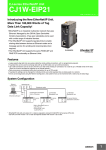
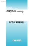
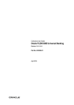
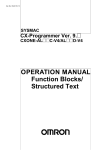
EtherNet/IP Monitor Tool
Operation Manual
Introduction
This manual documents the operating procedures of the EtherNet/IP Monitor Tool. It does not contain other
information, such as precautions. In actual use, obtain the operation manuals of the relevant CPU Units,
EtherNet/IP Units, and Support Software, read the required application information, including all
precautions, and adequately check operation before you use the EtherNet/IP Monitor Tool.
Trademarks
• EtherNet/IP is a registered trademark of the ODVA (Open DeviceNet Vendor Association).
• Windows, Windows XP, Windows Vista, and Windows 7 are registered trademarks of
Microsoft Corporation in the USA and other countries.
• Other company names and product names in this document are the trademarks or
registered trademarks of their respective companies.
Ethernet/IP Monitor Tool Operation Manual (R157)
Ethernet/IP Monitor Tool Operation Manual (R157)
Table of Contents
Table of Contents ............................................................................................. 1
Read and Understand this Manual.................................................................. 2
Related Manuals ............................................................................................... 5
1 The EtherNet/IP Monitor Tool .................................................................... 6
2 Function Specifications........................................................................... 10
2.1 Main Window............................................................................................................. 10
2.2 Menu Commands ...................................................................................................... 11
2.3 Toolbar....................................................................................................................... 11
2.4 Main Tab Page........................................................................................................... 12
2.4.1 Setting the Configuration Device ........................................................................ 13
2.4.2 Network Status Area ........................................................................................... 14
2.4.3 Connection Status Area ...................................................................................... 15
2.4.4 SYSMAC Gateway Service................................................................................. 16
2.4.5 Device Information Area...................................................................................... 16
2.5 Setting Tab Page ....................................................................................................... 17
2.5.1 Basic Tab Page ................................................................................................... 18
2.5.2 Producer Tab Page ............................................................................................. 25
2.5.3 Consumer Tab Page ........................................................................................... 27
2.5.4 Message Tab Page ............................................................................................. 29
2.5.5 User Define Tab Page ......................................................................................... 31
2.6 Monitoring Tab Page.................................................................................................. 36
2.6.1 Producer Tab Page ............................................................................................. 37
2.6.2 Consumer Tab Page ........................................................................................... 39
2.6.3 Message Tab Page ............................................................................................. 41
2.6.4 Connection Tab Page.......................................................................................... 43
2.6.5 Data Log Tab ...................................................................................................... 46
Ethernet/IP Monitor Tool Operation Manual (R157)
1
Read and Understand this Manual
Please read and understand this manual before using the product. Please consult your
OMRON representative if you have any questions or comments.
Warranty and Limitations of Liability
WARRANTY
OMRON's exclusive warranty is that the products are free from defects in materials and
workmanship for a period of one year (or other period if specified) from date of sale by OMRON.
OMRON MAKES NO WARRANTY OR REPRESENTATION, EXPRESS OR IMPLIED,
REGARDING NONINFRINGEMENT, MERCHANTABILITY, OR FITNESS FOR PARTICULAR
PURPOSE OF THE PRODUCTS. ANY BUYER OR USER ACKNOWLEDGES THAT THE
BUYER OR USER ALONE HAS DETERMINED THAT THE PRODUCTS WILL SUITABLY
MEET THE REQUIREMENTS OF THEIR INTENDED USE. OMRON DISCLAIMS ALL OTHER
WARRANTIES, EXPRESS OR IMPLIED.
LIMITATIONS OF LIABILITY
OMRON SHALL NOT BE RESPONSIBLE FOR SPECIAL, INDIRECT, OR CONSEQUENTIAL
DAMAGES, LOSS OF PROFITS OR COMMERCIAL LOSS IN ANY WAY CONNECTED WITH
THE PRODUCTS, WHETHER SUCH CLAIM IS BASED ON CONTRACT, WARRANTY,
NEGLIGENCE, OR STRICT LIABILITY.
In no event shall the responsibility of OMRON for any act exceed the individual price of the
product on which liability is asserted.
IN NO EVENT SHALL OMRON BE RESPONSIBLE FOR WARRANTY, REPAIR, OR OTHER
CLAIMS REGARDING THE PRODUCTS UNLESS OMRON'S ANALYSIS CONFIRMS THAT
THE PRODUCTS WERE PROPERLY HANDLED, STORED, INSTALLED, AND MAINTAINED
AND NOT SUBJECT TO CONTAMINATION, ABUSE, MISUSE, OR INAPPROPRIATE
MODIFICATION OR REPAIR.
2
Ethernet/IP Monitor Tool Operation Manual (R157)
Application Considerations
SUITABILITY FOR USE
OMRON shall not be responsible for conformity with any standards, codes, or regulations that
apply to the combination of products in the customer's application or use of the products.
At the customer's request, OMRON will provide applicable third party certification documents
identifying ratings and limitations of use that apply to the products. This information by itself is not
sufficient for a complete determination of the suitability of the products in combination with the
end product, machine, system, or other application or use.
The following are some examples of applications for which particular attention must be given.
This is not intended to be an exhaustive list of all possible uses of the products, nor is it intended
to imply that the uses listed may be suitable for the products:
• Outdoor use, uses involving potential chemical contamination or electrical interference, or
conditions or uses not described in this manual.
• Nuclear energy control systems, combustion systems, railroad systems, aviation systems,
medical equipment, amusement machines, vehicles, safety equipment, and installations
subject to separate industry or government regulations.
• Systems, machines, and equipment that could present a risk to life or property.
Please know and observe all prohibitions of use applicable to the products.
NEVER USE THE PRODUCTS FOR AN APPLICATION INVOLVING SERIOUS RISK TO LIFE
OR PROPERTY WITHOUT ENSURING THAT THE SYSTEM AS A WHOLE HAS BEEN
DESIGNED TO ADDRESS THE RISKS, AND THAT THE OMRON PRODUCTS ARE
PROPERLY RATED AND INSTALLED FOR THE INTENDED USE WITHIN THE OVERALL
EQUIPMENT OR SYSTEM.
PROGRAMMABLE PRODUCTS
OMRON shall not be responsible for the user's programming of a programmable product, or any
consequence thereof.
Ethernet/IP Monitor Tool Operation Manual (R157)
3
Disclaimers
CHANGE IN SPECIFICATIONS
Product specifications and accessories may be changed at any time based on improvements
and other reasons.
It is our practice to change model numbers when published ratings or features are changed, or
when significant construction changes are made. However, some specifications of the products
may be changed without any notice. When in doubt, special model numbers may be assigned to
fix or establish key specifications for your application on your request. Please consult with your
OMRON representative at any time to confirm actual specifications of purchased products.
DIMENSIONS AND WEIGHTS
Dimensions and weights are nominal and are not to be used for manufacturing purposes, even
when tolerances are shown.
PERFORMANCE DATA
Performance data given in this manual is provided as a guide for the user in determining
suitability and does not constitute a warranty. It may represent the result of OMRON's test
conditions, and the users must correlate it to actual application requirements. Actual
performance is subject to the OMRON Warranty and Limitations of Liability.
ERRORS AND OMISSIONS
The information in this manual has been carefully checked and is believed to be accurate;
however, no responsibility is assumed for clerical, typographical, or proofreading errors, or
omissions.
4
Ethernet/IP Monitor Tool Operation Manual (R157)
Related Manuals
• CPU Units
Man. No.
W472
Model numbers
CJ2H-CPU6 -EIP
Manual name
SYSMAC CJ Series CJ2 CPU Unit Hardware USER’S MANUAL
CJ2H-CPU6
CJ2M-CPU
W473
CJ2H-CPU6 -EIP
SYSMAC CJ Series CJ2 CPU Unit Software USER’S MANUAL
CJ2H-CPU6
CJ2M-CPU
W394
CS1 -CPU
-
SYSMAC CS Series, SYSMAC CJ Series, and SYSMAC One NSJ
CJ2H-CPU6 -EIP
Series Programmable Controllers INSTRUCTIONS REFERENCE
CJ2H-CPU6
MANUAL
CJ2M-CPU
CJ1 -CPU
NSJ
W474
-
-
CS1 -CPU
-
CJ2H-CPU6 -EIP
SYSMAC CS Series, SYSMAC CJ Series, and SYSMAC One NSJ
Series Programmable Controllers PROGRAMMING MANUAL
CJ2H-CPU6
CJ2M-CPU
CJ1 -CPU
NSJ
W342
-
-
CS1G/CS1H/CS1D/CS1W
SYSMAC CS/CJ/CP Series and SYSMAC One NSJ Series
CJ2H/CJ2M
Communications Commands REFERENCE MANUAL
CJ1G/CJ1H/CJ1M/CJ1W
CP1H/CP1L/CP1E/
NSJ
• Communications Units
W465
CS1W-EIP21
SYSMAC CS and CJ Series EtherNet/IP Units Communications
CJ1W-EIP21
Commands REFERENCE MANUAL
CJ2H-CPU6 -EIP
CJ2M-CPU3
• Support Software
Man. No.
Model numbers
Manual name
W463
CXONE-AL
C-V4
CX-One FA Integrated Tool Package SETUP MANUAL
W446
CXONE-AL
D-V4
CX-Programmer Ver. 9.
OPERATION MANUAL
CX-Programmer Ver. 9.
OPERATION MANUAL Function
W447
Blocks/Structured Text
W469
CX-Programmer Ver. 9.
W366
CX-Simulator Ver. 1.9 OPERATION MANUAL
W464
CX-Integrator Ver. 2.
W344
CX-Protocol Ver. 1.9 OPERATION MANUAL
W433
CX-Position Ver. 2.5 OPERATION MANUAL
W436
CX-Motion-NCF Ver. 1.9 OPERATION MANUAL
W448
CX-Motion-MCH OPERATION MANUAL
Ethernet/IP Monitor Tool Operation Manual (R157)
Operation Manual SFC Programming
OPERATION MANUAL
5
1 The EtherNet/IP Monitor Tool
• The EtherNet/IP Monitor Tool
The EtherNet/IP Monitor Tool is a software application for monitoring the communications status of
CS/CJ-series EtherNet/IP Units and SYSMAC Gateway EtherNet/IP and for setting connections for tag
data links.
If the configuration device is a SYSMAC Gateway, you can specify local devices on the same computer
or remote devices on other computers.
The system configuration supported by the EtherNet/IP Monitor Tool is shown below.
These devices can be
set and monitored.
EtherNet/IP
Monitor Tool
EtherNet/IP
Monitor Tool
SYSMAC
Gateway
These devices can be
set and monitored.
These devices can be
set and monitored.
EtherNet/IP
SYSMAC
Gateway
Cx1W-EIP21
CJ2x-EIP21
Network devices
6
Ethernet/IP Monitor Tool Operation Manual (R157)
• EtherNet/IP Monitor Tool Functions
The functions of the EtherNet/IP Monitor Tool are listed below.
Monitoring
Setting
Function
Details
Network status display
You can display the IP address, CIP port
number, and the operating status of the
configuration device.
Connection status display
You can display the tag type (Producer,
Consumer, UCMM, or Class 3), the total
number of connections, and the
communications status of the connections.
Tag status display
You can display the communications status
and data of producer and consumer tags.
You can display detailed information, such as
the total number of connections, the
connection time, and the time not connected.
Data logging
You can set the trigger conditions and log tag
data. Logged data is saved to a file. (This
function is supported only for SYSMAC
Gateway.)
Tag and connection settings
You can set producer tags, consumer tags,
and message tags. (Message tags are
enabled only for SYSMAC Gateway.)
Ethernet/IP Monitor Tool Operation Manual (R157)
7
• Supported Models
Model
Name
Remarks
CJ2H built-in EtherNet/IP port
(*1)
CJ1W-EIP21
CJ-series EtherNet/IP Unit
(*1)
CS1W-EIP21
CS-series EtherNet/IP Unit
(*1)
WS02-SGWC1
SYSMAC Gateway
(*2)
CJ2H-CPU
-EIP
(*1) Unit version 2.1 or later is required.
(*2) Software version 1.3 or higher is required.
• System Requirements
Item
Operating system (Japanese or
English)
Computer
Memory
Hard disk
Display
Disk drive
Communications port
8
System requirement
Microsoft Windows XP (Service Pack 3 or higher, 32-bit edition)
Microsoft Windows Vista
Microsoft Windows 7
A personal computer with the processor that is recommended by
Microsoft Corporation
The memory capacity that is recommended by Microsoft
Corporation
Approx. 20 MB or more of available hard disk space is required.
XGA (1,024 x 768), High Color, 16-bit or higher
CD-ROM or DVD-ROM drive
Ethernet port
Ethernet/IP Monitor Tool Operation Manual (R157)
• Installation Procedure
Execute the EtherNet/IP Monitor Tool setup program and install the software according to the
instructions that are displayed. There are setup programs available for both English and Japanese.
Select the setup program for the language to use. By default, the EtherNet/IP Monitor Tool is installed
in the following directory: C:\Program Files\OMRON\EtherNetIP Monitor Tool. OMRON EtherNetIP
Monitor Tool is also registered on the Windows Start Menu.
• Uninstallation Procedure
Select and delete the EtherNet/IP Monitor Tool from Add or Remove Programs or Programs and
Features in the Control Panel.
Ethernet/IP Monitor Tool Operation Manual (R157)
9
2 Function Specifications
2.1 Main Window
The Main Window of the EtherNet/IP Monitor Tool is shown below.
The Main Window is made up of the three following main tab pages.
10
Tab label
Description
Main
This tab page displays tables of the active status and connection status of the
devices (NICs) that are set on the Setting Tab Page. It is also used to start and
stop communications services for devices that are local SYSMAC Gateways.
Setting
This tab page is used to register EtherNet/IP connections and
produce/consume tags.
Monitoring
This tab page is used to monitor the connection status of produce and
consume tags.
Ethernet/IP Monitor Tool Operation Manual (R157)
2.2 Menu Commands
You can execute the following functions with the menu commands.
Menu command
Function
File − New
Creates a project.
File − Open
Opens an existing project.
File − Save
Saves the project.
File − Save As
Saves the project under a specified name. You can select to
save either an EtherNet/IP Monitor Tool project file or a device
configuration file (*.dvf) for use with the Network Configurator.
File − Connect
Connects to the configuration device if it is a remote device.
File − Disconnect
Disconnects from the configuration device.
File − Exit
Exits the EtherNet/IP Monitor Tool.
View − Toolbar
Shows or hides the toolbar.
View − Status bar
Shows or hides the status bar.
Help − Version Information
Displays the EtherNet/IP Monitor Tool's version information.
2.3 Toolbar
You can execute the following functions from the toolbar.
Toolbar icon
Function
Creates a project.
Opens an existing project.
Saves the project.
Connects to the configuration device if it is a remote device.
Disconnects from the configuration device.
Displays the EtherNet/IP Monitor Tool’s version information.
Ethernet/IP Monitor Tool Operation Manual (R157)
11
2.4 Main Tab Page
The Main Tab Page is shown below.
The following operations can be performed from the Main Tab Page.
12
Item
Function
Configuration Device
Select the configuration device to set and monitor. You can select
any of the devices that are given in the supported model list. For
SYSMAC Gateway, you can select either local or remote devices.
Network Status
This area is used to monitor and display the status of devices that
are registered on the Setting Tab Page.
Connection Status
This area is used to monitor and display the status of tags that are
registered on the Setting Tab Page.
SYSMAC Gateway Service
This area is used to start and stop the communications services if
the configuration device is a local SYSMAC Gateway device.
Device Information
This area displays information on the configuration device.
Ethernet/IP Monitor Tool Operation Manual (R157)
2.4.1 Setting the Configuration Device
The Configuration Device Box is used to select the device to set and monitor with the EtherNet/IP
Monitor Tool. You can select any of the devices that are given in the supported model list. For
SYSMAC Gateway, you can select either local or remote devices. The default is the device that was
previously selected. If a device was not previously selected, the default is Local: SYSMAC Gateway.
If the SYSMAC Gateway is not installed on the computer that is being used for operation, Local:
SYSMAC Gateway is not displayed.
The device information is displayed in the Device Information Area for the selected device.
If Remove Device is selected as the configuration device, the Connect Button in the toolbar is
enabled. The connection is made to the configuration device from the following dialog box.
If the selected device does not match the setting in the Configuration Device Box, the following error
message is displayed and the connection is not made: The Specified device type is not same as the
current configuration device type.
If the Disconnect Button is clicked, monitoring is stopped and the device is disconnected.
Ethernet/IP Monitor Tool Operation Manual (R157)
13
2.4.2 Network Status Area
The following information is displayed in the Network Status Area.
Item
Details
Local
This column displays the local and remote port names that are set
on the Setting Tab Page. If the configuration device is set to Remote
Devices, the local port names are not displayed. Only the remote
port names are displayed.
IP Address
This column displays the port names that are assigned to the
address names.
CIP Port
The CIP port numbers of the port names are displayed only if the
configuration device is set to Local: SYSMAC Gateway.
Status
This column displays whether the active status of the device is OK.
The open/closed status of the ports are displayed if the
configuration device is set to Local: SYSMAC Gateway.
The status can also be identified using the icon that is displayed
beside the port name.
The icon and status displays change with the device status as shown in the following table.
Icon
Status display
Status
---
• Local Port
Local: SYSMAC Gateway: Servicing is stopped.
• Remote Port
There is no corresponding status.
OK
• Local Port
Local: SYSMAC Gateway: The port is open.
• Remote Port
There is a device at the IP address.
NG
• Local Port
Local: SYSMAC Gateway: The port is closed.
• Remote Port
There is no device at the IP address.
To confirm whether a device is at the IP address, PING is used to send and receive an ICMP packet.
ICMP packets are consecutively sent to all IP addresses. The ICMP packet response monitoring time
is 500 ms, and the cycle for checking for devices at the IP addresses is 5,000 ms.
14
Ethernet/IP Monitor Tool Operation Manual (R157)
2.4.3 Connection Status Area
The following information is displayed in the Connection Status Area.
Item
Details
Tag Type
The following are displayed as tag types.
•
Producer: Connection-type class-1 produce tags
•
Consumer: Connection-type class-1 consume tags
•
UCMM: Connection-type UCMM message tags
•
Class 3: Connection-type class-3 message tags
Total Count
This column displays the total number of types that are registered on
the Setting Tab Page.
OK Count
This column displays the total number of tags for which
communications ended normally.
The icons that are displayed next to the tag type will change according to the connection status as
described in the following table.
Icon
Status
The total count is 0 or the device is offline.
The registered tag exists and all connections are normal.
The registered tag exists, but at least one of the connections is not established.
The registered tag exists and there are no connections.
UCMM/class 3 is supported only for Local: SYSMAC Gateway. The cycle for checking the status of
the tags is 500 ms.
If the Details Button is clicked, the following dialog box is displayed to show the status of the tags.
Ethernet/IP Monitor Tool Operation Manual (R157)
15
The Detail Connection Status Dialog Box displays the following information on property tab pages for
each tab type.
Item
Details
Tag Name
This column displays the tag names.
Status
This column displays the tag connection status.
Normal: OK
Error (not connected): NG
The icons that are displayed next to the tag name will change according to the connection status as
described in the following table.
Icon
Status
Offline
Operation is normal.
The connection is not established or an error occurred.
The Jump to Connection Monitor Button is clicked to close the dialog box and jump to the
Monitoring-Connection Tab Page.
2.4.4 SYSMAC Gateway Service
If the configuration device is set to Local: SYSMAC Gateway, you can manage the SYSMAC
Gateway Service. In other cases, the Start Button, the Stop Button, and other features are disabled.
2.4.5 Device Information Area
The Device Information Area displays the device information for the device that is currently being set
or monitored.
16
Ethernet/IP Monitor Tool Operation Manual (R157)
2.5 Setting Tab Page
The Setting Tab Page is shown below.
The following operations can be performed from the Setting Tab Page.
Tab label
Function
Basic
This tab page is for port settings and logging configuration of local
and remote networks.
Producer
This tab page is used to set produce tags.
Consumer
This tab page is used to set consume tags.
Message
This tab page is used to set message tags.
User Define
This tab page is used to set user definitions for displaying tag data.
Ethernet/IP Monitor Tool Operation Manual (R157)
17
2.5.1 Basic Tab Page
The following operations can be performed from the Basic Tab Page.
Item
Function
Local Network Port
This area is used for local network port settings.
The following settings are made according to configuration device
that is set on the Main Tab Page.
• Local SYSMAC Gateway
SYSMAC Gateway ports
• Remote Devices
Network ports on the local computer that are used to access
configuration devices
Remote Network Port
This area is used to set configuration device ports.
Logging Configuration
This area is used to set the folder for storing log data and to set the
data log.
Upload
This button is used to upload parameters from a device.
Download
This button is used to download parameters to a device.
Verify
This button is used to verify parameters with the device.
Reset
This button resets the device.
Resetting is possible only if the configuration device is set to
SYSMAC Gateway.
Clear Connect/Disconnect
Counter
This button is used to clear the connection/disconnection counter
for the configuration device tags.
2.5.1.1 Setting Local Network Ports
If the configuration device is set to Local: SYSMAC Gateway on the Main Tab Page, the following
dialog box is displayed to set a port when the New Button is clicked.
Item
Port Name
CIP Port No.
IP Address
18
Details
This box is used to specify the port name. A maximum of 32 bytes of
characters can be set.
This box is used to specify the CIP port number. A value of 2 to 5 must be
entered as the port number. However, if the SYSMAC Gateway is not
multiport or if the number of supported ports is different, the port number
is determined by the SYSMAC Gateway specifications. Port numbers that
have already been set cannot be specified.
This box is used to specify the IP address of the port. IP addresses that
have already been set cannot be specified.
Ethernet/IP Monitor Tool Operation Manual (R157)
If the Browse Button is clicked, the following dialog box is displayed to obtain the IP address from
a list of interfaces on the computer. If there is only one interface, the dialog box is not shown and
the relevant IP address is obtained.
If the configuration device is set to Remote Device on the Main Tab Page, the following dialog box
is displayed to select the interface to use to connect to the device when the New Button is clicked.
If there is only one interface, the dialog box is not shown and the relevant IP address is obtained.
To edit settings for existing ports, the Edit Button is clicked after selecting the setting to edit, or
the setting is double-clicked. The same dialog box as for creating a new port is displayed and can
be edited. The settings cannot be changed if the configuration device is set to Remote Devices
on the Main Tab Page.
To delete an existing port, the Delete Button is clicked after selecting the settings. The settings
are deleted when the Yes Button is clicked after the delete confirmation dialog box is displayed.
The settings cannot be changed if the configuration device is set to Remote Devices on the Main
Tab Page.
Ethernet/IP Monitor Tool Operation Manual (R157)
19
2.5.1.2 Setting Remote Network Ports
The New Button is clicked to display the following dialog box to set a port. These settings cannot
be made if there are no local ports enabled in the local port settings.
Item
Details
Node Name
This box is used to specify the configuration device name.
A maximum of 32 bytes of characters can be set.
Local Port to use
This box is used to specify the local port to use to communicate with
the configuration device. A list of ports set in Edit Local Network Port
Dialog Box is displayed in the selection list.
Port Type
This box is used to specify the type of end point port. The following
types can be set.
0: Default
1: RA compatible
IP Address
This box is used to specify the IP address of the configuration
device. IP addresses that have already been set cannot be specified.
If the Browse Button is clicked, the following dialog box is displayed to browse the configuration
devices and obtain the IP address. The local port settings must be completed in advance when
executing this operation.
20
Ethernet/IP Monitor Tool Operation Manual (R157)
To edit settings for existing ports, the Edit Button is clicked after selecting the setting to edit, or
the setting is double-clicked. The same dialog box as for creating a new port is displayed and can
be edited.
To delete an existing port, the Delete Button is clicked after selecting the settings. The settings
are deleted when the Yes Button is clicked after the delete confirmation dialog box is displayed.
Ethernet/IP Monitor Tool Operation Manual (R157)
21
2.5.1.3 Logging Configuration Area
The following items are set in Logging Configuration Area. These settings are disabled if the
configuration device is set to Remote Devices.
Item
Details
Communication Log,
Output Folder
This box is used to specify the folder where the communications log
is stored.
A new file is output every day and every hour.
Example: The output file for 23:15 on August 12, 2011 is
SgwComLog_2011_08_12-23.txt.
Enable Log Output
This check box is used to enable outputting a communications log.
The default is the previous setting. If there is no previous setting, the
default is to disable outputting the log.
Delete Int.
The Set Button is used to specify the interval between deletions of
communications log files. Data is all maintained only for the
specified maximum number of days, including that day. All other data
is deleted.
Data Log, Output Folder
This box is used to specify the folder where the data log is stored.
Enable Data Log
This check box is used to enable data log output. The default is the
previous setting. If there is no previous setting, the default is to
disable outputting the log.
Edit Data Logging
Parameters
This button is used to edit data logging parameters.
The Browse Buttons that are next to the input boxes are clicked to select an existing folder as the
log output folder.
The following items are output as a communications log.
22
Item
Details
Forward Open/Close
Class-1 forward open/close information is output.
Service Start/Stop
Information on starting and stopping the SYSMAC Gateway service
is output.
Download Start/Stop
Information on starting and stopping downloads of configuration
data is output.
Explicit Message
Information on the explicit messages that were sent and received
with the explicit message server is output.
Error
Error information, such as connection timeouts for explicit
messages, is output.
Ethernet/IP Monitor Tool Operation Manual (R157)
The Edit Data Logging Parameters Button is clicked to display the following dialog box and set
the logging parameters.
Up to ten logging tags can be registered. The logging buffer size is 1 to 256 Kbytes. The logging
cycle is 1,000 to 60,000 ms.
• Trigger Areas
Item
Details
Tag Name
This box is used to specify the name of the tag that is used as a
trigger.
Offset
This box is used to specify the tag data byte offset for starting to
trigger logging.
Type
This box is used to specify the data type to use from the offset
position for triggering logging. BYTE, WORD, or DWORD (default)
can be specified.
Mask
This box is used to specify a hexadecimal value as the mask for data
to use to trigger logging.
Match
This box is used to specify a hexadecimal value as the match value
for data to use to trigger logging.
Ethernet/IP Monitor Tool Operation Manual (R157)
23
• Trigger Condition Area
Item
Details
Trigger 1 OK
Logging is performed if the value of the data of the specified size
from the starting offset position for the tag set in the Trigger 1 Area is
the same as the match value when the mask is applied.
Trigger 1 NG
Logging is performed if the value of the data of the specified size
from the starting offset position for the tag set in the Trigger 1 Area is
not the same as the match value when the mask is applied.
Trigger 2 OK
Logging is performed if the value of the data of the specified size
from the starting offset position for the tag set in the Trigger 2 Area is
the same as the match value when the mask is applied.
Trigger 2 NG
Logging is performed if the value of the data of the specified size
from the starting offset position for the tag set in the Trigger 2 Area is
not the same as the match value when the mask is applied.
Multi
Logging is performed for ANDs or ORs of the above conditions.
2.5.1.4 Upload
This button is used to upload parameters from the connected device. If the configuration device is
not set to Local: SYSMAC Gateway, the uploaded data includes only the parameters that can be
set with the Network Configurator.
2.5.1.5 Download
This button downloads the current parameters to the connected device. If the configuration
device is not set to Local: SYSMAC Gateway, the downloaded data includes only the parameters
that can be set with the Network Configurator.
2.5.1.6 Verify
This button is used to verify parameters with the connected device. If the configuration device is
not set to Local: SYSMAC Gateway, the verified data is performed only for the parameters that
can be set with the Network Configurator.
2.5.1.7 Reset
This button resets the connected device.
Resetting is possible only if the configuration device is set to SYSMAC Gateway.
2.5.1.8 Clear Connect/Disconnect Counter
This button is used to clear the connection/disconnection counter for all of the tags of the
connected device.
24
Ethernet/IP Monitor Tool Operation Manual (R157)
2.5.2 Producer Tab Page
The Producer Tab Page is used to set produce tags. The tab page is shown below.
Tags that are set on this tab page have with only one tag in each tag set. The specified tag names
are treated as tag set names.
The New Button is clicked to display the following dialog box to set a tag.
Ethernet/IP Monitor Tool Operation Manual (R157)
25
Item
Function
Tag Name
This box is used to set the tag names. The characters that can be
input and the number of bytes of characters that can be input
depend on the configuration device.
Size
This box is used to specify the tag size. The supported size settings
depend on the configuration device.
RPI Range
These options are used to enable or disable the RPI ranges. If the
Disable Option is selected, values cannot be entered into the cells in
the Max RPI, Min RPI, and Default RPI Columns.
Max RPI
This box is used to specify the maximum RPI. The supported RPI
ranges depend on the configuration device.
Min RPI
This box is used to specify the minimum RPI. The supported RPI
ranges depend on the configuration device.
Default RPI
This box is used to specify the default RPI. The supported RPI
ranges depend on the configuration device.
User Define
This box is used to specify the user-defined tag data displays.
To edit settings for existing ports, the Edit Button is clicked after selecting the setting to edit, or
the setting is double-clicked. The same dialog box as for creating a new port is displayed and can
be edited.
To delete an existing port, the Delete Button is clicked after selecting the settings. The settings
are deleted when the Yes Button is clicked after the delete confirmation dialog box is displayed.
26
Ethernet/IP Monitor Tool Operation Manual (R157)
2.5.3 Consumer Tab Page
The Consumer Tab Page is used to set consume tags. The tab page is shown below.
Tags that are set on this tab page have only one tag in each tag set. The specified tag names are
treated as tag set names.
The New Button is clicked to display the following dialog box to set a tag.
Ethernet/IP Monitor Tool Operation Manual (R157)
27
Item
Function
Tag Name
This box is used to set the tag names. The characters that can be
input and the number of bytes of characters that can be input
depend on the configuration device.
Size
This box is used to specify the tag size. The supported size settings
depend on the configuration device.
Connection Type
This box is used to specify the connection type (multicast or point to
point).
RPI
This box is used to specify the RPI. The supported RPI ranges
depend on the configuration device.
Timeout
This box is used to specify the timeout multiplier.
Remote Node
This box is used to specify the remote node to which the connection
is established.
Remote Tag Name
This box is used to specify the produce tag of the remote node to
which the connection is established.
User Define
This box is used to specify the user-defined tag data displays.
To edit settings for existing ports, the Edit Button is clicked after selecting the setting to edit, or
the setting is double-clicked. The same dialog box as for creating a new port is displayed and can
be edited.
To delete an existing port, the Delete Button is clicked after selecting the settings. The settings
are deleted when the Yes Button is clicked after the delete confirmation dialog box is displayed.
28
Ethernet/IP Monitor Tool Operation Manual (R157)
2.5.4 Message Tab Page
The Message Tab Page is used to set message tags. The tab page is shown below. These settings
are disabled if the configuration device is not set to Local: SYSMAC Gateway.
The tags that are specified on this tab page are registered only as normal tags. They are not
registered as class-1 tags.
The New Button is clicked to display the following dialog box to set a tag.
Ethernet/IP Monitor Tool Operation Manual (R157)
29
Item
Function
Tag Name
This box is used to set the tag names. The characters that can be
input and the number of bytes of characters that can be input
depend on the configuration device.
Size
This box is used to specify the tag size. The supported size settings
depend on the configuration device.
Connect Type
Use this box to specify the connection type (UCMM or class 3).
Remote Node
This box is used to specify the remote node to which the connection
is established.
Remote Tag Name
This box is used to specify the produce tag of the remote node to
which the connection is established.
User Define
This box is used to specify the user-defined tag data displays.
To edit settings for existing ports, the Edit Button is clicked after selecting the setting to edit, or
the setting is double-clicked. The same dialog box as for creating a new port is displayed and can
be edited.
To delete an existing port, the Delete Button is clicked after selecting the settings. The settings
are deleted when the Yes Button is clicked after the delete confirmation dialog box is displayed.
30
Ethernet/IP Monitor Tool Operation Manual (R157)
2.5.5 User Define Tab Page
The User Define Tab Page is used to set definitions for displaying tag data. The tab page is shown
below.
Select a user-defined name list to display the user-defined information.
2.5.5.1 Setting User Define Options
The Edit Options Button is clicked to edit the options when creating user definitions. The
following dialog box is displayed.
Item
Function
Default Data Type
This box is used to specify the default data type when specifying the
size of the user definition. WORD or DWORD (default) can be
specified.
Pre Defined File
This box is used to specify a file containing predefined user
definitions. The Browse Button is clicked to specify a file. The user
definitions in the specified file are displayed in the user definition list
by default.
Ethernet/IP Monitor Tool Operation Manual (R157)
31
The format of the predefined file is given below.
Section
UserDef
UserDef#
Keyword
Count
Name
Size
MemberCount
Member#
Details
Specifies the number of user definitions.
Specifies the contents of the user definitions.
Set “#” to a value between 1 and the value that you
set for UserDef.
Specifies the user definition name.
Specifies the user definition size in bytes.
Specifies the number of members.
Specifies the member information.
Set “#” to a value between 1 and the value that you
set for MemberCount in UserDef#.
The following format is used for the above member information. Fields are delineated by
commas.
Field No.
1
2
Field name
Name
Type
3
4
Unit
ChildDefineName
Details
Specifies the member name.
Specifies the data type of the member.
You can set any of the following text strings.
BIT
BYTE
WORD
DWORD
STRUCT
Number of data elements
If you set the data type to STRUCT, specify the
name of the user definition to use. For other data
types, omit this field.
Example:
[UserDef]
Count=2
[UserDef1]
Name=SampleDefine
Size=10
MemberCount=2
Member1=Data1, WORD, 1
Member2=Data2, DWORD, 2
[UserDef2]
Name=SampleDefine2
Size=12
MemberCount=2
Member1=Data1, WORD, 1
Member2=Data2, STRUCT, 1, SampleDefine
32
Ethernet/IP Monitor Tool Operation Manual (R157)
2.5.5.2 Creating and Deleting User Definitions
To create a new user definition, click the New Button next to the user definition name. The Create
User Define Dialog Box is shown below.
The following settings are made in the Create User Define Dialog Box.
Item
Function
Define Name
This box is used to specify the definition name. A maximum of
48 characters can be entered.
Size
This box is used to specify the overall size of the user definition
in bytes. The size can be set to between 1 and 1,444 bytes.
However, the value must be a multiple of the default data type
that is specified in operation settings.
The OK Button is clicked to add the definition name to the user definition name list and register
the following member. This member is always displayed as the last user definition member. It
cannot be edited or deleted.
Member Name
Remained Address
Unit
BYTE
Size
Overall user definition size − Registered member size (BYTE)
A user definition is deleted if the user definition is selected in the user definition name list and the
Delete Button is clicked. The OK Button is clicked to delete the user definition after confirmation.
Predefined user definitions cannot be deleted.
Click the Create Define File Button to save a user definition that you have created in a file.
Ethernet/IP Monitor Tool Operation Manual (R157)
33
2.5.5.3 Creating, Editing, and Deleting User Definition Members
The Add Button at the right side of the tab page is clicked to add a user definition member. The
Edit User Define Member Dialog Box is shown below.
The following settings are made in the Create User Define Dialog Box.
Item
Function
Member Name
This box is used to specify the user definition member name. A maximum of
48 characters can be entered.
Unit
This box is used to specify the data type to use for the member. The data
types that can be specified are given below.
• Bit
• BYTE
• WORD
• DWORD
Size
This box is used to specify the data size to use for the member in increments
of the size of the data type. This can be set to any value at which the total
size for all members does not exceed the total size of the user definition.
The OK Button is clicked to add the member to the user definition information. Members are
added as according to the position of the cursor when the Add Button is clicked. When a member
is added, edited, or deleted, the size of the remaining addresses (Remained Address) is
automatically updated as the last member. If the size is not a multiple of the default data type that
is set in user definition options, a warning message is displayed at the bottom of the User Define
Tab Page.
Cursor selection
Position of addition
Member is not selected.
The member is added as the last member.
Member is selected.
The member is added after the selected member.
A user definition member is selected and then the Edit Button at the right side of the tab page is
clicked to edit the selected member. A similar dialog box as that for adding a member is displayed.
The OK Button is clicked after editing the member to update the user definition information. The
Remained Address member, which is the last member, cannot be edited.
A user definition member is selected and then the Delete Button at the right side of the tab page
is clicked to delete the selected member. The OK Button is clicked to delete the member after
confirmation. The Remained Address member, which is the last member, cannot be deleted.
To change the position where a member is displayed, the member is selected and the Up Button
or the Down Button at the right side of the tab page is clicked. The Remained Address member,
which is the last member, cannot be moved.
34
Ethernet/IP Monitor Tool Operation Manual (R157)
2.5.5.4 Uploading and Downloading User Definitions
The Upload Button is clicked to upload as a user definition a user structure that is defined in the
SYSMAC Gateway. The Download Button is clicked to download a user definition as a SYSMAC
Gateway user structure. Uploading and downloading are possible only if the configuration device
is set to Local: SYSMAC Gateway.
Data is assigned as given below when uploading or downloading.
• Upload
SYSMAC Gateway
Tool
Struct Name
The user definition name.
Struct Member Name
The user definition member name.
Member Data Type
BOOL → Bit
1-channel data → WORD
2-channel data → DWORD
4-channel data → 2 DWORD elements
Other → An error occurs and the structure is not uploaded.
• Download
Tool
SYSMAC Gateway
User Define Name
The name of the structure.
User Define Member Name
The name of the structure member.
Member Data Type
Bit → BOOL
WORD → WORD
DWORD → DWORD
If the number of members or the number of nesting levels exceeds the number that is supported
by the SYSMAC Gateway, the download is not performed.
Ethernet/IP Monitor Tool Operation Manual (R157)
35
2.6 Monitoring Tab Page
The Monitoring Tab Page is shown below.
The following operations can be performed from the Monitoring Tab Page.
Tab label
Function
Producer
This tab page is used to monitor produce tags.
Consumer
This tab page is used to monitor consume tags.
Message
This tab page is used to monitor message tags.
Connection
This tab page is used to monitor connection information on produce
tags and consume tags.
Data Log
This tab page is used to control data logging and to display data
logs.
If devices or device versions that are not supported are connected, “---” will be displayed for the
monitored data.
36
Ethernet/IP Monitor Tool Operation Manual (R157)
2.6.1 Producer Tab Page
2.6.1.1 Monitoring Tag Status
The Producer Tab Page is used to monitor the following data for all produce tags.
Tab label
Function
Status
The following icons are displayed next to the tag name to indicate
the connection status.
Offline
Operation is normal.
The connection is not established or
an error occurred.
Size
This column displays the tag size.
Target IP
This column displays the IP address of the target. The multicast
addresses are displayed for a multicast connection.
Connection ID
This column displays the connection ID.
The cycle for checking the status of the tags is 500 ms.
Ethernet/IP Monitor Tool Operation Manual (R157)
37
2.6.1.2 Monitoring Tag Data
The data of the tag that is selected with the cursor in the Tag List Area is monitored
The monitoring cycle for tag data is the same as the cycle for checking the status of the tags, i.e.,
500 ms.
You can select one of the following display formats for the tag data. If the display format is HEX,
DEC, or BIN, the display type can be selected from BYTE, WORD, or DWORD (default).
Display format
Description
HEX
This option displays the tag data in hexadecimal in units of the
specified data type.
Examples for data of 0x12345678
Display type: BYTE
78 56 34 12
Display type: WORD 5678 1234
Display type: DWORD 12345678
DEC
This option displays the tag data in decimal in units of the specified
data type.
Examples for data of 0x12345678
Display type: BYTE
120 86 52 18
Display type: WORD 22136 4660
Display type: DWORD 305419896
BIN
This option displays the tag data in binary in units of the specified data
type.
Examples for data of 0x01020304
Display type: BYTE
00000100 00000011 00000010 00000001
Display type: WORD 0000001100000100 0000000100000010
Display type: DWORD 00000001000000100000001100000100
ASCII
This option displays tag data by byte in ASCII.
Example for data of 0x31323334
4321
ASCII (SWAP)
This option swaps the bytes in tag data to display the data by WORD
in ASCII.
Example for data of 0x31323334
3412
To use user definitions for the tag data display format, select the User Define Check Box. Data is
displayed in the user-defined format that is specified for each tag. The display format for each
configuration member is shown below.
Configuration member
data type
38
Display format
Bit
The data is displayed as TRUE or FALSE.
Not bit
The tag data is displayed with the display format that is shown
above for each unit that is defined in the user definitions.
Ethernet/IP Monitor Tool Operation Manual (R157)
2.6.2 Consumer Tab Page
The Consumer Tab Page is used to set monitor tags. The tab page is shown below.
2.6.2.1 Monitoring Tag Status
The Consumer Tab Page is used to monitor the following data for all consume tags.
Tab label
Function
Status
The following icons are displayed next to the tag name to indicate
the connection status.
Offline
Operation is normal.
The connection is not established or
an error occurred.
Size
This column displays the tag size.
Connection Time
This column displays the total connection time.
The cycle for checking the status of the tags is 500 ms.
Ethernet/IP Monitor Tool Operation Manual (R157)
39
2.6.2.2 Monitoring Tag Data
The data of the tag that is selected with the cursor in the Tag List Area is monitored.
The monitoring cycle for tag data is the same as the cycle for checking the status of the tags, i.e.,
500 ms.
You can select one of the following display formats for the tag data. If the display format is HEX,
DEC, or BIN, the display type can be selected from BYTE, WORD, or DWORD (default).
Display format
Description
HEX
This option displays the tag data in hexadecimal in units of the
specified data type.
Examples for data of 0x12345678
Display type: BYTE
78 56 34 12
Display type: WORD 5678 1234
Display type: DWORD 12345678
DEC
This option displays the tag data in decimal in units of the specified
data type.
Examples for data of 0x12345678
Display type: BYTE
120 86 52 18
Display type: WORD 22136 4660
Display type: DWORD 305419896
BIN
This option displays the tag data in binary in units of the specified data
type.
Examples for data of 0x01020304
Display type: BYTE
00000100 00000011 00000010 00000001
Display type: WORD 0000001100000100 0000000100000010
Display type: DWORD 00000001000000100000001100000100
ASCII
This option displays tag data by byte in ASCII.
Example for data of 0x31323334
4321
ASCII (SWAP)
This option swaps the bytes in tag data to display the data by WORD
in ASCII.
Example for data of 0x31323334
3412
To use user definitions for the tag data display format, select the User Define Check Box. Data is
displayed in the user-defined format that is specified for each tag. The display format for each
configuration member is shown below.
Configuration member
data type
40
Display format
Bit
The data is displayed as TRUE or FALSE
Not bit
The tag data is displayed with the display format that is shown
above for each unit that is defined in the user definitions.
Ethernet/IP Monitor Tool Operation Manual (R157)
2.6.3 Message Tab Page
The Message Tab Page is used to monitor message tags. The tab page is shown below.
2.6.3.1 Monitoring Tag Status
The Message Tab Page is used to monitor the following data for all message tags.
Tab label
Function
Status
The following icons are displayed next to the tag name to indicate the
connection status.
Offline
Operation is normal.
The connection is not established or
an error occurred.
Size
This column displays the tag size.
The cycle for checking the status of the tags is 500 ms.
Ethernet/IP Monitor Tool Operation Manual (R157)
41
2.6.3.2 Monitoring Tag Data
The data of the tag that is selected with the cursor in the Tag List Area is monitored.
The monitoring cycle for tag data is the same as the cycle for checking the status of the tags, i.e.,
500 ms.
You can select one of the following display formats for the tag data. If the display format is HEX,
DEC, or BIN, the display type can be selected from BYTE, WORD, or DWORD (default).
Display format
Description
HEX
This option displays the tag data in hexadecimal in units of the
specified data type.
Examples for data of 0x12345678
Display type: BYTE
78 56 34 12
Display type: WORD 5678 1234
Display type: DWORD 12345678
DEC
This option displays the tag data in decimal in units of the specified
data type.
Examples for data of 0x12345678
Display type: BYTE
120 86 52 18
Display type: WORD 22136 4660
Display type: DWORD 305419896
BIN
This option displays the tag data in binary in units of the specified data
type.
Examples for data of 0x01020304
Display type: BYTE
00000100 00000011 00000010 00000001
Display type: WORD 0000001100000100 0000000100000010
Display type: DWORD 00000001000000100000001100000100
ASCII
This option displays tag data by byte in ASCII.
Example for data of 0x31323334
4321
ASCII (SWAP)
This option swaps the bytes in tag data to display the data by WORD
in ASCII.
Example for data of 0x31323334
3412
To use user definitions for the tag data display format, select the User Define Check Box. Data is
displayed in the user-defined format that is specified for each tag. The display format for each
configuration member is shown below.
Configuration member
data type
42
Display format
Bit
The data is displayed as TRUE or FALSE
Not bit
The tag data is displayed with the display format that is shown
above for each unit that is defined in the user definitions.
Ethernet/IP Monitor Tool Operation Manual (R157)
2.6.4 Connection Tab Page
The Connection Tab Page is used to monitor the connection status of consume tags and produce
tags. The tab page is shown below. It is used to monitor only connections that are specified as being
connection-type class-1 connections.
The cycle for checking the status of the connections is 500 ms.
Ethernet/IP Monitor Tool Operation Manual (R157)
43
2.6.4.1 Producer List
The Producer List Area is used to monitor the following items for each tag. Inactive tags are not
monitored.
44
Item
Details
Tag Name
The name of the produce tag is displayed.
The following icons are displayed next to the tag name to indicate
the connection status.
Offline
Operation is normal.
The connection is not established or
an error occurred.
Size
This column displays the tag size. The size is displayed in bytes.
Connection Time
The total connected time for the tag is displayed. The time is
displayed in milliseconds.
Disconnection Time
The total disconnected time for the tag is displayed. The time is
displayed in milliseconds.
Connection Count
This column displays the connection count.
Connected Consumer
The number of consumers connected to the tag is displayed.
Related Consumer List
The following information on connected consumers is displayed.
Consumer Name
The name of the consumer is displayed. The name is displayed if
the device at the IP address is registered on the Setting Tab Page.
The name is displayed as Device xx (where xx is the device
number) if it is not registered.
IP Address
The IP address of the consumer is displayed.
Connection Time
The total connected time for the consumer is displayed. The time is
displayed in milliseconds.
Disconnection Time
The total disconnected time for the consumer is displayed. The time
is displayed in milliseconds.
Destination IP Address
The destination IP address is displayed. The destination multicast
addresses are displayed if it is a multicast connection.
O->T RPI
The O->T RPI is displayed. The time is displayed in milliseconds.
T->O RPI
The T->O RPI is displayed. The time is displayed in milliseconds.
O->T Timeout
The O->T timeout time is displayed. The time is displayed in
milliseconds.
T->O Timeout
The T->O timeout time is displayed. The time is displayed in
milliseconds.
O->T API
The O->T API is displayed. The time is displayed in milliseconds.
T->O API
The T->O API is displayed. The time is displayed in milliseconds.
O->T Connection ID
The O->T connection ID is displayed as a hexadecimal value.
T->O Connection ID
The T->O connection ID is displayed as a hexadecimal value.
Ethernet/IP Monitor Tool Operation Manual (R157)
2.6.4.2 Consumer List
The Consumer List Area is used to monitor the following items for each tag. Inactive tags are not
monitored.
Item
Details
Tag Name
The name of the consume tag is displayed.
The following icons are displayed next to the tag name to indicate
the connection status.
Offline
Operation is normal.
The connection is not established or
an error occurred.
Size
This column displays the tag size. The size is displayed in bytes.
Connection Time
The total connected time for the tag is displayed. The time is
displayed in milliseconds.
Disconnection Time
The total disconnected time for the tag is displayed. The time is
displayed in milliseconds.
Destination IP Address
The destination IP address is displayed. The destination addresses
are displayed if it is a multicast connection.
Related Producer List
The following information on related producers is displayed
(basically 1).
Produce Tag Name
The related producer tag name is displayed.
Remote IP Address
The IP Address of the related producer is displayed.
O->T RPI
The O->T RPI is displayed. The time is displayed in milliseconds.
T->O RPI
The T->O RPI is displayed. The time is displayed in milliseconds.
O->T Timeout
The O->T timeout time is displayed. The time is displayed in
milliseconds.
T->O Timeout
The T->O timeout time is displayed. The time is displayed in
milliseconds.
O->T API
The O->T API is displayed. The time is displayed in milliseconds.
T->O API
The T->O API is displayed. The time is displayed in milliseconds.
O->T Connection ID
The O->T connection ID is displayed as a hexadecimal value.
T->O Connection ID
The T->O connection ID is displayed as a hexadecimal value.
Ethernet/IP Monitor Tool Operation Manual (R157)
45
2.6.5 Data Log Tab
The Data Log Tab Page is used to perform logging for the tags that are specified as trigger conditions
in the data logging settings. The tab page is shown below.
Logging is performed for operation of the following buttons on the Data Log Tab Page. The maximum
size of the data that is logged is the buffer size that is specified in the data logging settings.
46
Item
Function
Start
The Start Button is clicked to start logging the specified tag. The
Stop Button is clicked to stop logging the specified tag. If the Cyclic
Check Box is selected, tag data is obtained on the specified cycle.
Stop
This button stops logging and displays the logging data in a list.
Start Trigger
This button monitors whether the trigger condition is met when the
button is clicked, and starts logging the specified tag after the trigger
condition is met. Logging stops when the logging buffer is full. This
button cannot be used if the Cyclic Check Box is selected.
Stop Trigger
Logging of the specified tag starts when this button is clicked and
logging stops when the specified trigger condition is met. This button
cannot be used if the Cyclic Check Box is selected.
Cyclic
This check box is used to perform logging of the specified tags at the
logging cycle that was specified in the data logging settings. Logging
using a trigger condition cannot be performed if the Cyclic Logging
Check Box is selected.
Ethernet/IP Monitor Tool Operation Manual (R157)
The following information is shown in the logging results.
Item
Function
No.
The logging data number is displayed starting at 1.
Tag Name
This column displays the tag names.
Data
This column displays the tag data in a hexadecimal byte string.
Detailed tag data can be displayed in a similar manner by selecting the tag on the Producer Tab Page
or the Consumer Tab Page.
Ethernet/IP Monitor Tool Operation Manual (R157)
47
OMRON Corporation
Industrial Automation Company
Authorized Distributor:
Tokyo, JAPAN
Contact: www.ia.omron.com
Regional Headquarters
OMRON EUROPE B.V.
Wegalaan 67-69-2132 JD Hoofddorp
The Netherlands
Tel: (31)2356-81-300/Fax: (31)2356-81-388
OMRON ELECTRONICS LLC
One Commerce Drive Schaumburg,
IL 60173-5302 U.S.A.
Tel: (1) 847-843-7900/Fax: (1) 847-843-7787
OMRON ASIA PACIFIC PTE. LTD.
No. 438A Alexandra Road # 05-05/08 (Lobby 2),
Alexandra Technopark,
Singapore 119967
Tel: (65) 6835-3011/Fax: (65) 6835-2711
OMRON (CHINA) CO., LTD.
Room 2211, Bank of China Tower,
200 Yin Cheng Zhong Road,
PuDong New Area, Shanghai, 200120, China
Tel: (86) 21-5037-2222/Fax: (86) 21-5037-2200
© OMRON Corporation 2011 All Rights Reserved.
In the interest of product improvement,
specifications are subject to change without notice.
Cat. No. R157-E1-02
0112