1
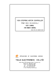
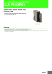
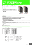
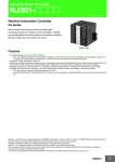
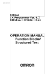
CJ-series EtherNet/IP Unit CJ1W-EIP21 CSM_CJ1W-EIP21_DS_E_7_1 Introducing the New EtherNet/IP Unit. More Than 180,000 Words of Tag Data Link Capacity! • EtherNet/IP is an industrial multivendor network that uses Ethernet. Managed by the ODVA (Open DeviceNet Vendors Association), it has open standards and is used with a wide range of industrial devices. • The EtherNet/IP Unit supports tag data links to enable sharing data between devices at Ethernet nodes and a message service for sending and receiving data when required. • The EtherNet/IP Unit supports the same FINS/UDP and FINS/TCP functionality as Ethernet Units. CJ1W-EIP21 Features • Large-capacity tag data links are easily enabled by simply setting connections, with no programming required. • Tag data links can be used to exchange data with up to 256 nodes over up to 256 connections. • Up to 256 connections can be set per Unit with up to 722 words of data per connection, for a total of up to 184,832 words of link data. (There is no limit to the data link capacity for the overall network.) • Data concurrency is maintained within each connection (for up to 722 words). • Tag data link settings can be changed for individual Units even while tag data links are being used on a network. • Errors can be diagnosed using the Network Configurator, and system errors can be monitored with a wide array of status flags. System Configuration Network Configurator Switching hub Twisted-pair cable 100 m max. CS1W-EIP21 EtherNet/IP Unit for CS-series CJ1W-EIP21 EtherNet/IP Unit CJ1W-EIP21 EtherNet/IP Unit Ethernet (LAN) port CS-series PLC CJ-series PLC NJ-series Machine Automation Controller * Built-in EtherNet/IP port on CJ2 CPU Unit (CJ2H-CPU6@-EIP/ CJ2M-CPU3@) * EtherNet/IP Unit with unit version 2.1 or later is required to connect C1JW-EIP21 to NJ-series CPU Unit. Use CPU Unit with version 1.01 or later and Sysmac Studio with version 1.02 or later. 1 CJ1W-EIP21 Ordering Information International Standards • The standards are abbreviated as follows: U: UL, U1: UL (Class I Division 2 Products for Hazardous Locations), C: CSA, UC: cULus, UC1: cULus (Class I Division 2 Products for Hazardous Locations), CU: cUL, N: NK, L: Lloyd, and CE: EC Directives. • Contact your OMRON representative for further details and applicable conditions for these standards. EtherNet/IP Unit Unit type Product name Specifications Communications cable Communications functions Shielded twisted-pair (STP) cable Categories: 100 Ω at 5, 5e Tag Data Link Functions, Message Communications Functions No. of unit numbers Units per CPU Unit allocated Current consumption (A) 5V system Model 24 V system Standards EtherNet/IP Unit CJ1 CPU Bus Unit 8 max. *1 1 − 0.41 CJ1W-EIP21 *2 UC1, N, L, CE *1. Up to four EtherNet/IP Units can be connected to a NJ CPU Unit. Up to seven EtherNet/IP Units can be connected to a CJ2H-CPU6@-EIP. Up to two EtherNet/IP Units can be connected to a CJ2M CPU Unit. *2. EtherNet/IP Unit with unit version 2.1 or later is required to connect C1JW-EIP21 to NJ-series CPU Unit. Use CPU Unit with version 1.01 or later and Sysmac Studio with version 1.02 or later. Industrial Switching Hubs Specifications Product name Appearance Functions Failure detection Accessories 3 No • Power supply connector Quality of Service (QoS): EtherNet/IP control data priority Failure detection: Broadcast storm and LSI error detection 10/100BASE-TX, Auto-Negotiation Industrial Switching Hubs Current consumption (A) No. of ports 5 No 5 Yes • Power supply connector • Connector for informing error 0.22 Model Standards W4S1-03B UC, CE 0.22 W4S1-05B 0.22 W4S1-05C CE Recommended Network Devices The following table shows the devices recommended for use with the EtherNet/IP. Part Manufacturer Switching Hub Model number Inquires Phoenix Contact FL SWITCH SFN 8TX (8 ports) Phoenix Contact USA Customer Service Contec USA, Inc. SH8008(FIT)H (8 ports) CONTEC USA Inc. Cisco Systems, Inc. WS-C2955T-12 (12 ports) Cisco Systems, Inc. Main Corporate HQ 100BASE-TX Twisted-pair cable F-LINK-E 0.5mm × 4P Fujikura Fujikura America, Inc. − EtherNet/IP compliant cable Connectors (Modular plug) STP Plug Panduit Corporation MPS588 Panduit Corporation US Headquarters Boots Tsuko Company MK boot (IV) LB Tsuko Company Japan Headquarters Note: 1. Always use a switching hub when using tag data links in the network. 2. If a repeater hub is used for EtherNet/IP tag data links (cyclic communications), the network's communications load will increase, data collisions will occur frequently, and stable communications will be impossible. Mountable Racks NJ system Model CJ1W-EIP21 Unit version 2.0 CPU Rack Expansion Rack 4 Units (per CPU Unit) *1 CJ1 system CPU Rack Expansion Backplane 8 Units (per CPU Unit) *2 CP1H system NSJ system CP1H PLC NSJ Controller Expansion Backplane 2 Units *3 Not supported 8 Units *1. EtherNet/IP Unit with unit version 2.1 or later is required to connect C1JW-EIP21 to NJ-series CPU Unit. Use CPU Unit with version 1.01 or later and Sysmac Studio with version 1.02 or later. *2. Up to seven EtherNet/IP Units can be connected to a CJ2H-CPU6@-EIP. Up to two EtherNet/IP Units can be connected to a CJ2M CPU Unit. *3. A CP1W-EXT01 CJ Unit Adaptor is required. Sysmac® is a trademark or registered trademark of OMRON Corporation in Japan and other countries for OMRON factory automation products. Windows are either registered trademarks or trademarks of Microsoft Corporation in the United States and/or other countries. Other company names and product names in this document are the trademarks or registered trademarks of their respective companies. 2 CJ1W-EIP21 EtherNet/IP Units Specifications Item Specifications Model number CJ1W-EIP21 Type 100Base-TX *1 Applicable PLCs NJ-series, CJ (CJ1, CJ2) series, CP1H, and NSJ series PLCs. Unit classification CJ-series CPU Bus Unit Mounting location CPU Rack or Expansion Rack Number of Units that can be mounted NJ-series System : 4 max. (including Expansion Racks) CJ series System and NSJ series System: 8 max. (including Expansion Racks) *2 CP1H System: 2 max. Allocated CIO Area words (CPU Bus Unit words) CPU Unit words used Allocated DM Area words (CPU Bus Unit words) User-set area CPU Bus Unit System Setup Non-volatile memory within EtherNet/IP Unit (See note.) Transfer specifications 25 words/Unit (one unit number’s words) These words contain control bits and flags, the target node PLC’s operating and error information, Unit status, communications status, registered/normal target node information, and FINS/TCP connection status. 100 words/Unit (one unit number’s words) These words contain the IP address display/setting area. Any usable data area words Target node PLC’s operating and error information, and registered/normal target node information Not used. The following settings are stored in the EtherNet/IP Unit’s non-volatile memory. Note: Unlike the regular Ethernet Units, the CPU Bus Unit Setup Area in the CPU Unit is not used for these settings. 1. Unit Setup (communications settings for the EtherNet/IP Unit, such as the IP address, DNS server settings, host name, baud rate, FINS/UDP settings, and FINS/TCP settings) 2. Tag data link settings (device parameters) Media access method CSMA/CD Modulation method Baseband Transmission paths Star form Baud rate 100 Mbit/s (100Base-TX) Transmission media Shielded twisted-pair (STP) cable Categories: 100 Ω at 5, 5e Transmission distance 100 m (distance between hub and node) Number of cascade connections There is no limitation when a switching hub is used. Current consumption (Unit) 410 mA max. at 5 V DC Weight 94 g max. Dimensions 31 × 90 × 65 mm (W × H × D) Other general specifications Other specifications conform to the general specifications of the CJ-series. *1. If tag data links are being used, use 100Base-TX. Otherwise, 10Base-T can be used, but this is not recommended. *2. Up to seven EtherNet/IP Units can be connected to a CJ2H-CPU6@-EIP. Up to two EtherNet/IP Units can be connected to a CJ2M CPU Unit. 3 CJ1W-EIP21 Communications Specifications Item Tag data links (Cyclic communications) CIP service CJ1 Number of connections 256 Packet interval (refresh cycle) 0.5 to 10,000 ms (in 0.5-ms units) Can be set independently for each connection. (Data is refreshed over the network at the preset interval and does not depend on the number of nodes.) Allowed communications bandwidth per Unit Number of tag sets Tag types Number of tags per connection (= 1 tag set) Maximum link data size per node Maximum data size per connection *3 Number of registrable tag sets Maximum size of 1 tag set Maximum number of tags that can be refreshed per CPU Unit cycle *4 Data that can be refreshed per CPU Unit cycle *4 Explicit messaging *8 Specifications CJ2 NJ Changing tag data link parameters during operation Multicast packet filter function *7 Class 3 (connected) UCMM (unconnected) CIP routing *9 FINS/UDP FINS/TCP EtherNet/IP conformance test FINS service Ethernet interface 6000pps *1 256 CIO Area, DM Area, EM Area, Holding Area, Work Area, and network symbols *2 8 (7 tags when the tag set contains the controller status) 184,832 words 504 bytes (252 words) or 1444 bytes (722 words) *2 Data synchronicity is maintained within each connection. 256 (1 connection = 1 tag set) 722 words (The controller status uses 1 word when the tag set contains the PLC status.) Output/Transmission (CPU to EtherNet/IP): 19 Input/Reception (EtherNet/IP to CPU): 20 *5 Output/Transmission (CPU to EtherNet/IP): 7,405 words Input/Reception (EtherNet/IP to CPU): 7,405 words Output/Transmission (CPU to EtherNet/IP): 256 Input/Reception (EtherNet/IP to CPU): 256 Output/Transmission (CPU to EtherNet/IP): 6,432 words Input/Reception (EtherNet/IP to CPU): 6,432 words Supported *6 Supported Number of connections: 128 Number of clients that can communicate at one time: 32 max. Number of servers that can communicate at one time: 32 max. Supported CJ1W-EIP21, CS1W-EIP21, NJ-501-@@@@, NJ-301-@@@@, CJ2H-CPU@@-EIP, CJ2M-CPU3@ Not supported Supported Not supported 16 connections max. Conforms to A8 10BASE-T or 100BASE-TX Auto Negotiation or fixed settings *1. In this case, pps means "packets per second" and indicates the number of packets that can be processed in one second. *2. Network symbols can be used only by the NJ501-@@@@, NJ301-@@@@, CJ2H-CPU6@-EIP and CJ2M-CPU3@. *3. To use 505 to 1,444 bytes as the data size, the system must support the Large Forward Open standard (an optional CIP specification). The CS/CJ-series Units support this standard, but before connecting to nodes of other companies, confirm that those devices also support it. *4. If the maximum data size is exceeded, the data refreshing with the CPU Unit will extend over two or more cycles. *5. If status layout is selected in the user settings, the maximum number of tags that can be received is 19 tags. *6. If parameters are changed in the EtherNet/IP Unit, however, the EtherNet/IP Unit will be restarted. When other nodes are communicating with the affected node, the communications will temporarily time out and automatically recover later. *7. Because the EtherNet/IP Unit is equipped with an IGMP client, unnecessary multicast packets can be filtered by using a switching hub that supports IGMP snooping. *8. The EtherNet/IP Unit uses the TCP/UDP port numbers shown in the following table. Service Used by system Tag data links Class3, UCMM DNS BOOTP client FINS/UDP service FINS/TCP service FTP SNTP SNMP SNMP trap Protocol CJ1/CJ2 --UDP TCP/UDP UDP --UDP TCP TCP UDP UDP UDP Port number NJ UDP CJ1/CJ2 --- Remarks NJ 2223, 2224 2222 44818 53 UDP 9600 9600 20, 21 123 161 162 NJ Fixed value --- ----- CJ1/CJ2 68 ----21 Port numbers in the Unit Setup can be changed with the CX-Programmer. Port numbers in the Unit Setup can be changed with the Sysmac Studio. *9. When NJ-Series CPU Units is described, Supported only by the EtherNet/IP Units with unit version 2.1 or later and NJ-Series CPU Units with unit version 1.01 or later. 4 CJ1W-EIP21 Unit Versions and Software Versions The following versions of the Sysmac Studio, CX-Programmer and Network Configurator are required to set EtherNet/IP Units. Yes:Supported, ---:Not supported Sysmac Studio *1 Ver.1.01 or lower Ver.1.02 ----------Yes CJ1W-EIP21 Ver.1.0 Ver.2.0 Ver.2.1 Ver.7.1 or lower ------- CX-Programmer *2 Ver.8.0 or higher Ver.8.02 or higher Yes *3 Yes Yes Yes Yes Yes Network Configurator for EtherNet/IP Ver.3.40 or lower Ver.3.50 or higher Yes Yes Yes Yes --Yes *1. Available only when connecting with NJ-series CPU Units. *2. Available only when connecting with CJ1/CJ2-series CPU Units. *3. The most recent version of the common module for CX-One version 3.@@ must be installed. Network Configurator Requirements The Network Configurator Ver. 3.0 or higher is a software package designed for building, setting, and controlling a multi-vendor EtherNet/IP Network using OMRON's EtherNet/IP. It is included in CX-One version 3.0. The Network Configurator provides the following functions for building, setting, and controlling EtherNet/IP. Item Operating environment Network connection method Serial interface Ethernet interface Location on Network Number of Units that can be connected to Network Main functions Network control functions Configuration functions Supported file formats Specification Refer to the CX-One Setup Manual (Cat. No. W463). CXONE-AL@@C-V@/CXONE-AL@@D-V@ CS1/CJ1 CJ2 NJ CPU Unit’s Peripheral or RS-232C port CPU Unit’s USB or RS-232C port CPU Unit’s USB port CPU Unit’s Ethernet port EtherNet/IP Unit’s Ethernet port EtherNet/IP Unit’s Ethernet port A single node address is used (only when directly connected to EtherNet/IP). A single Network Configurator per Network (More than one Configurator cannot be used in the same system.) • The Network configuration can be created and edited regardless of whether the Network Configurator is online or offline. • The Network configuration can be read from a file or the network. The EDS files used by the Network Configurator can be installed and deleted. Configurator network configuration files (*.ncf) Configuration files (*.ncf) created using the Network Configurator for EtherNet/IP (version 2) can be imported by selecting External Data - Import from the File Menu. External Interface CJ1W-EIP21 LED Indicators These indicators display the Unit and network status. Unit number setting switch This rotary switch sets the unit number on the CPU Unit with one hexadecimal digit. Node address setting switches These two rotary switches set the node address for the EtherNet/IP Unit on the EtherNet/IP network with two hexadecimal digits. This setting is also used as the host ID in the default IP address (192.168.250.@). Label showing IP address A label that can be used to show the IP address and subnet mask is provided. Ethernet connector The network is connected with shielded twisted-pair cable. Ethernet Connectors The following standards and specifications apply to the connectors for the Ethernet twisted-pair cable. • Electrical specifications: Conforming to IEEE802.3 standards. • Connector structure: RJ45 8-pin Modular Connector (conforming to ISO 8877) Connector pin 1 2 3 4 5 6 7 8 Hood Signal name Transmission data + Transmission data − Reception data + Not used. Not used. Reception data − Not used. Not used. Frame ground Abbr. TD+ TD− RD+ − − RD− − − FG Signal direction Output Output Input − − Input − − − 5 CJ1W-EIP21 Functional Comparsion of EtherNet/IP Functionality OK:Supported, ---:Not supported EtherNet/IP Unit (built-in port on CJ2 CPU Unit) Unit version 1.0 Unit version 2.0 Unit version 2.1 Built-in EtherNet/ IP port on NJseries CPU Unit Tag data link communications service OK OK OK OK CIP message communications service OK OK OK OK --- Socket service --- --- --- OK OK File transfer (FTP) --- OK OK OK OK Mail send/receive --- --- --- --- OK Web functions --- --- --- --- OK Automatic adjustment of PLC/Controller’s internal clock --- OK OK OK OK Error history OK OK OK OK *1 OK Response to PING command OK OK OK OK OK SNMP/SNMP trap --- OK OK OK --- CIDR function for IP addresses --- OK OK OK --- Online connection via EtherNet/IP using CX-One/Sysmac Studio --- OK OK --- --- Online connection via EtherNet/IP using Network Configurator OK OK OK OK --- Mounting in a Controller with an NJseries CPU Unit --- --- OK *2 --- --- Item CJ-series Ethernet Unit --- *1. This is equivalent to the event log of the built-in EtherNet/IP port of an NJ-series Controller. *2. You cannot use the following functions if you connect to the CPU Unit through an EtherNet/IP Unit. • Going online with a CPU Unit from the Sysmac Studio. (However, you can go online from the Network Configurator.) • Troubleshooting from an NS-series PT Dimensions (Unit: mm) CJ1W-EIP21 31mm 65mm 90mm 6 CJ1W-EIP21 Related Manuals Manual number Model Name Contents CS1W-EIP21 CJ1W-EIP21 CJ2H-CPU@@-EIP CJ2M-CPU3@ EtherNet/IP Units Operation Manual Provides information on operating and installing EtherNet/IP Units, including details on basic settings, tag data links, and FINS communications. Refer to the Communications Commands Reference Manual (W342) for details on FINS commands that can be sent to CS-series and CJ-series CPU Units when using the FINS communications service. Refer to the Ethernet Units Operation Manual Construction of Applications (W421) for details on constructing host applications that use FINS communications. W495 CJ1W-EIP21 CJ-series EtherNet/IP Units Operation Manual for NJ-series CPU Unit Information on using an EtherNet/IP Unit that is connected to an NJ-series CPU Unit is provided. Information is provided on the basic setup, tag data links, and other features. Use this manual together with the NJ-series CPU Unit Hardware User’s Manual (Cat. No. W500) and NJ-series CPU Unit Software User’s Manual (Cat. No. W501). W421 CS1W-ETN21 CJ1W-ETN21 Ethernet Units Operation Manual Construction of Applications Provides information on constructing host applications for 100Base-TX Ethernet Units, including functions for sending/receiving mail, socket service, automatic clock adjustment, FTP server functions, and FINS communications. W342 CS1G/H-CPU@@H CS1G/H-CPU-@@V1 CS1W-SCU21 CS1W-SCB21/41 CJ1G/H-CPU@@H CJ1G-CPU@@ CJ1W-SCU41 Communications Commands Reference Manual Describes the C-series (Host Link) and FINS communications commands used when sending communications commands to CS-series and CJ-series CPU Units. W463 CXONE-AL@@C/D-V@ CX-One Setup Manual Describes the setup procedures for the CX-One. Information is also provided on the operating environment for the CX-One. W465 7 Read and Understand This Catalog Please read and understand this catalog before purchasing the products. Please consult your OMRON representative if you have any questions or comments. Warranty and Limitations of Liability WARRANTY OMRON's exclusive warranty is that the products are free from defects in materials and workmanship for a period of one year (or other period if specified) from date of sale by OMRON. OMRON MAKES NO WARRANTY OR REPRESENTATION, EXPRESS OR IMPLIED, REGARDING NON-INFRINGEMENT, MERCHANTABILITY, OR FITNESS FOR PARTICULAR PURPOSE OF THE PRODUCTS. ANY BUYER OR USER ACKNOWLEDGES THAT THE BUYER OR USER ALONE HAS DETERMINED THAT THE PRODUCTS WILL SUITABLY MEET THE REQUIREMENTS OF THEIR INTENDED USE. OMRON DISCLAIMS ALL OTHER WARRANTIES, EXPRESS OR IMPLIED. LIMITATIONS OF LIABILITY OMRON SHALL NOT BE RESPONSIBLE FOR SPECIAL, INDIRECT, OR CONSEQUENTIAL DAMAGES, LOSS OF PROFITS OR COMMERCIAL LOSS IN ANY WAY CONNECTED WITH THE PRODUCTS, WHETHER SUCH CLAIM IS BASED ON CONTRACT, WARRANTY, NEGLIGENCE, OR STRICT LIABILITY. In no event shall the responsibility of OMRON for any act exceed the individual price of the product on which liability is asserted. IN NO EVENT SHALL OMRON BE RESPONSIBLE FOR WARRANTY, REPAIR, OR OTHER CLAIMS REGARDING THE PRODUCTS UNLESS OMRON'S ANALYSIS CONFIRMS THAT THE PRODUCTS WERE PROPERLY HANDLED, STORED, INSTALLED, AND MAINTAINED AND NOT SUBJECT TO CONTAMINATION, ABUSE, MISUSE, OR INAPPROPRIATE MODIFICATION OR REPAIR. Application Considerations SUITABILITY FOR USE OMRON shall not be responsible for conformity with any standards, codes, or regulations that apply to the combination of products in the customer's application or use of the products. At the customer's request, OMRON will provide applicable third party certification documents identifying ratings and limitations of use that apply to the products. This information by itself is not sufficient for a complete determination of the suitability of the products in combination with the end product, machine, system, or other application or use. The following are some examples of applications for which particular attention must be given. This is not intended to be an exhaustive list of all possible uses of the products, nor is it intended to imply that the uses listed may be suitable for the products: Outdoor use, uses involving potential chemical contamination or electrical interference, or conditions or uses not described in this catalog. Nuclear energy control systems, combustion systems, railroad systems, aviation systems, medical equipment, amusement machines, vehicles, safety equipment, and installations subject to separate industry or government regulations. Systems, machines, and equipment that could present a risk to life or property. Please know and observe all prohibitions of use applicable to the products. NEVER USE THE PRODUCTS FOR AN APPLICATION INVOLVING SERIOUS RISK TO LIFE OR PROPERTY WITHOUT ENSURING THAT THE SYSTEM AS A WHOLE HAS BEEN DESIGNED TO ADDRESS THE RISKS, AND THAT THE OMRON PRODUCTS ARE PROPERLY RATED AND INSTALLED FOR THE INTENDED USE WITHIN THE OVERALL EQUIPMENT OR SYSTEM. PROGRAMMABLE PRODUCTS OMRON shall not be responsible for the user's programming of a programmable product, or any consequence thereof. Disclaimers CHANGE IN SPECIFICATIONS Product specifications and accessories may be changed at any time based on improvements and other reasons. It is our practice to change model numbers when published ratings or features are changed, or when significant construction changes are made. However, some specifications of the products may be changed without any notice. When in doubt, special model numbers may be assigned to fix or establish key specifications for your application on your request. Please consult with your OMRON representative at any time to confirm actual specifications of purchased products. DIMENSIONS AND WEIGHTS Dimensions and weights are nominal and are not to be used for manufacturing purposes, even when tolerances are shown. PERFORMANCE DATA Performance data given in this catalog is provided as a guide for the user in determining suitability and does not constitute a warranty. It may represent the result of OMRON’s test conditions, and the users must correlate it to actual application requirements. Actual performance is subject to the OMRON Warranty and Limitations of Liability. ERRORS AND OMISSIONS The information in this document has been carefully checked and is believed to be accurate; however, no responsibility is assumed for clerical, typographical, or proofreading errors, or omissions. 2012.5 In the interest of product improvement, specifications are subject to change without notice. OMRON Corporation Industrial Automation Company http://www.ia.omron.com/ (c)Copyright OMRON Corporation 2012 All Right Reserved.